chapter 7: dislocations & strengthening...
TRANSCRIPT

ISSUES TO ADDRESS:
• Why are dislocations observed primarily in metals
and alloys?
• How are strength and dislocation motion related?
• How do we increase strength?
• How can heat treatment change strength and other properties?
Chapter 7:
Dislocations & Strengthening Mechanisms
Reference: Callister chapter 7 and 8th ed.

Dislocation Motion
Dislocations & plastic deformation
• Cubic & hexagonal metals - plastic deformation is by plastic
shear or slip where one plane of atoms slides over adjacent
plane by defect motion (dislocations).
• If dislocations don't move, deformation doesn't occur!
Adapted from Fig. 7.1, Callister 8e.
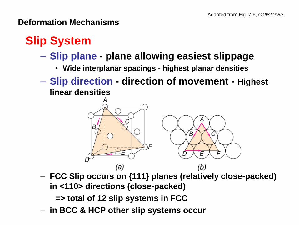
Slip System
– Slip plane - plane allowing easiest slippage • Wide interplanar spacings - highest planar densities
– Slip direction - direction of movement - Highest
linear densities
– FCC Slip occurs on {111} planes (relatively close-packed)
in <110> directions (close-packed)
=> total of 12 slip systems in FCC
– in BCC & HCP other slip systems occur
Deformation Mechanisms Adapted from Fig. 7.6, Callister 8e.

Slip Systems in Cubic Metals:
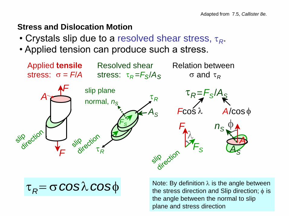
Note: By definition is the angle between
the stress direction and Slip direction; is
the angle between the normal to slip
plane and stress direction
Stress and Dislocation Motion
• Crystals slip due to a resolved shear stress, tR. • Applied tension can produce such a stress.
slip plane
normal, ns
Resolved shear stress: tR = F s /A s
AS
tR
tR
FS
Relation between s and tR
tR = FS /AS
F cos A / cos
F
FS
nS
AS A
Applied tensile stress: = F/A s
F A
F
st coscosR
Adapted from 7.5, Callister 8e.

• Condition for dislocation motion: CRSS ttR
• Crystal orientation can make
it easy or hard to move dislocation 10-4 GPa to 10-2 GPa
typically
st coscosR
Critical Resolved Shear Stress
tR = 0
=90°
s
tR = s /2 =45° =45°
s
tR = 0
=90°
s
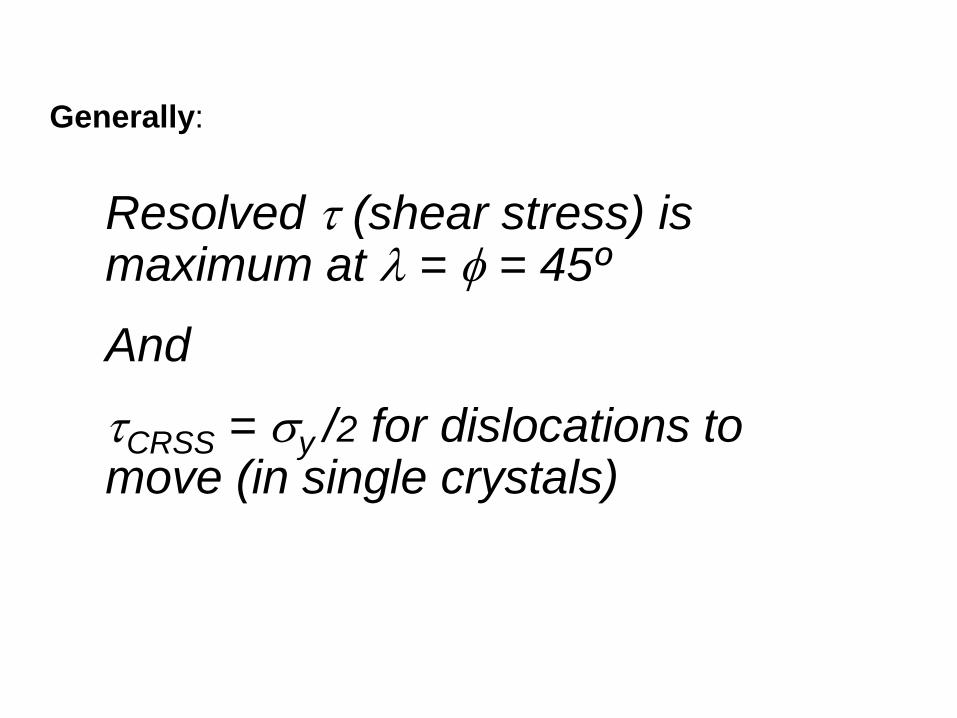
Generally:
Resolved t (shear stress) is maximum at = = 45º
And
tCRSS = sy /2 for dislocations to move (in single crystals)
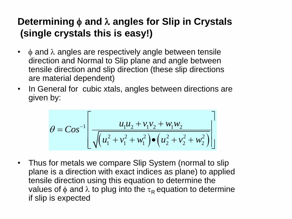
Determining and angles for Slip in Crystals
(single crystals this is easy!)
• and angles are respectively angle between tensile direction and Normal to Slip plane and angle between tensile direction and slip direction (these slip directions are material dependent)
• In General for cubic xtals, angles between directions are given by:
• Thus for metals we compare Slip System (normal to slip plane is a direction with exact indices as plane) to applied tensile direction using this equation to determine the values of and to plug into the tR equation to determine if slip is expected
1 1 2 1 2 1 2
2 2 2 2 2 2
1 1 1 2 2 2
u u v v w wCos
u v w u v w
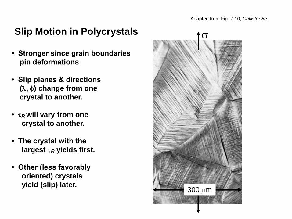
• Stronger since grain boundaries
pin deformations
• Slip planes & directions
(, ) change from one
crystal to another.
• tR will vary from one
crystal to another.
• The crystal with the
largest tR yields first.
• Other (less favorably
oriented) crystals
yield (slip) later.
Slip Motion in Polycrystals s
300 mm
Adapted from Fig. 7.10, Callister 8e.

After seeing the effect of poly crystalline materials
we can say (as related to strength):
• Ordinarily ductility is sacrificed when an alloy is strengthened.
• The relationship between dislocation motion and mechanical behavior of metals is significance to the understanding of strengthening mechanisms.
• The ability of a metal to plastically deform depends on the ability of dislocations to move.
• Virtually all strengthening techniques rely on this simple principle: Restricting or Hindering dislocation motion renders a material harder and stronger.
• We will consider strengthening single phase metals by: grain size reduction, solid-solution alloying, and strain hardening

Strategies for Strengthening:
1: Reduce Grain Size
• Grain boundaries are
barriers to slip.
• Barrier "strength"
increases with
Increasing angle of
misorientation.
• Smaller grain size:
more barriers to slip.
• Hall-Petch Equation: 21 /
yoyield dk ss
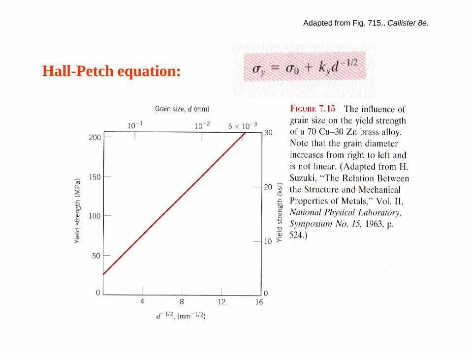
Hall-Petch equation:
Adapted from Fig. 715., Callister 8e.

Grain Size Reduction Techniques:
•Increase Rate of solidification from the liquid phase.
•Perform Plastic deformation followed by an appropriate heat
treatment.
Notes:
Grain size reduction also improves toughness of many alloys.
Small-angle grain boundaries are not effective in interfering
with the slip process because of the small crystallographic
misalignment across the boundary.
Boundaries between two different phases are also impediments to
movements of dislocations.

Impurity atoms distort the lattice & generate stress.
Stress can produce a barrier to dislocation motion.
Strategies for Strengthening:
2: Solid Solutions
• Smaller substitutional
impurity
Impurity generates local stress at A
and B that opposes dislocation
motion to the right.
A
B
• Larger substitutional
impurity
Impurity generates local stress at C
and D that opposes dislocation
motion to the right.
C
D
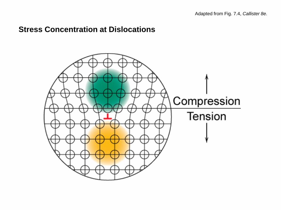
Stress Concentration at Dislocations
Adapted from Fig. 7.4, Callister 8e.
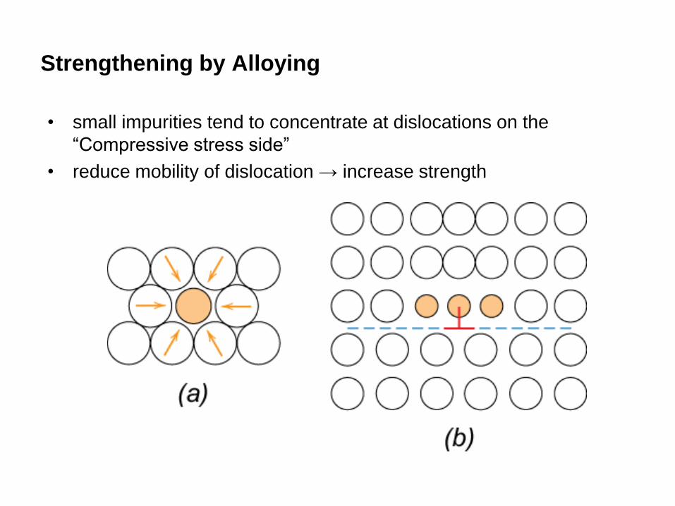
Strengthening by Alloying
• small impurities tend to concentrate at dislocations on the
“Compressive stress side”
• reduce mobility of dislocation → increase strength
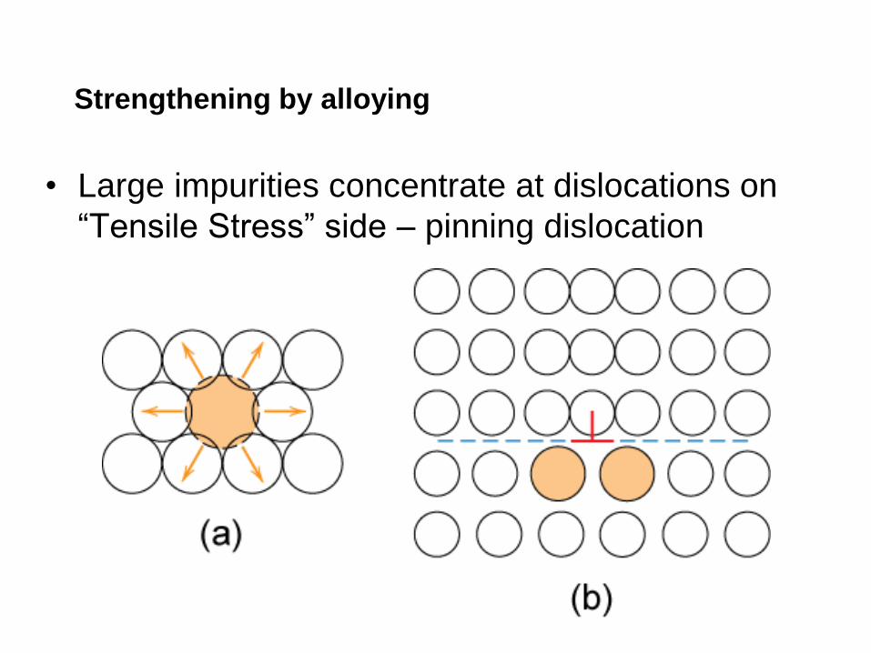
Strengthening by alloying
• Large impurities concentrate at dislocations on
“Tensile Stress” side – pinning dislocation
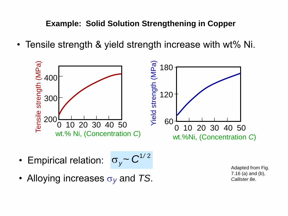
Example: Solid Solution Strengthening in Copper
• Tensile strength & yield strength increase with wt% Ni.
• Empirical relation:
• Alloying increases sy and TS.
21 /
y C~sAdapted from Fig.
7.16 (a) and (b),
Callister 8e.
Tensile
str
ength
(M
Pa)
wt.% Ni, (Concentration C)
200
300
400
0 10 20 30 40 50 Yie
ld s
trength
(M
Pa)
wt.%Ni, (Concentration C)
60
120
180
0 10 20 30 40 50

• Hard precipitates are difficult to shear. Ex: Ceramics in metals (SiC
in Iron or Aluminum).
• Result:
sGb
y
Strategies for Strengthening:
3. Precipitation Strengthening
Slipped part of slip plane
Side View
precipitate
Top View Unslipped part of slip plane
λ
Large shear stress needed to move
dislocation toward precipitate and
shear it.
Dislocation “advances” but
precipitates act as “pinning” sites
with spacing λ. which “multiplies”
Dislocation density
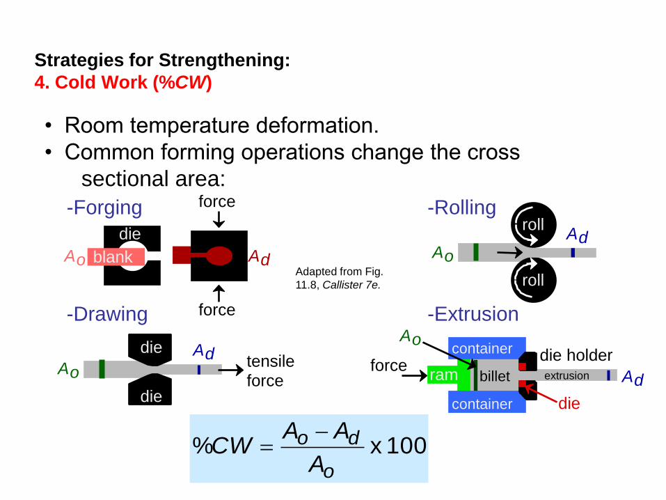
Strategies for Strengthening:
4. Cold Work (%CW)
• Room temperature deformation.
• Common forming operations change the cross
sectional area:
Adapted from Fig.
11.8, Callister 7e.
-Forging
A o A d
force
die
blank
force -Drawing
tensile force
A o
A d die
die
-Extrusion
ram billet
container
container
force die holder
die
A o
A d extrusion
100 x %o
do
A
AACW
-Rolling
roll
A o
A d roll

• Ti alloy after cold working:
• Dislocations entangle and
multiply
• Thus, Dislocation motion
becomes more difficult.
Adapted from Fig.
4.6, Callister 8e.
(Fig. 4.6 is courtesy
of M.R. Plichta,
Michigan
Technological
University.)
During Cold Work
0.9 mm

Result of Cold Work
Dislocation density (rd) =
– Carefully grown single crystal
ca. 103 mm-2
– Deforming sample increases density
109-1010 mm-2
– Heat treatment reduces density
105-106 mm-2
• Yield stress increases
as rd increases:
total dislocation length
unit volume
large hardening
small hardening
s
e
s y0
s y1

Impact of Cold Work, low Carbon steel:
Lo-Carbon Steel!
Adapted from Fig. 7.20,
Callister 8e.
• Yield strength (sy) increases.
• Tensile strength (TS) increases.
• Ductility (%EL or %AR) decreases.
As cold work is increased

• What is the tensile strength &
ductility after cold working?
%6.35100 x %2
22
o
do
r
rrCW
Cold Work Analysis
Copper
D0=15,2 mm Dd=12,2 mm
Cold worked rod

• What is the tensile strength &
ductility after cold working to 35,6%?
Adapted from Fig. 7.19, Callister 8e. (Fig. 7.19 is adapted from Metals Handbook: Properties and Selection: Iron
and Steels, Vol. 1, 9th ed., B. Bardes (Ed.), American Society for Metals, 1978, p. 226; and Metals Handbook:
Properties and Selection: Nonferrous Alloys and Pure Metals, Vol. 2, 9th ed., H. Baker (Managing Ed.), American
Society for Metals, 1979, p. 276 and 327.)
Cold Work Analysis
% Cold Work
100
300
500
700
Cu
20 0 40 60
yield strength (MPa)
% Cold Work
tensile strength (MPa)
200
Cu
0
400
600
800
20 40 60
340MPa
TS = 340MPa
ductility (%EL)
% Cold Work
20
40
60
20 40 60 0 0
Cu
7%
%EL = 7% YS = 300 MPa
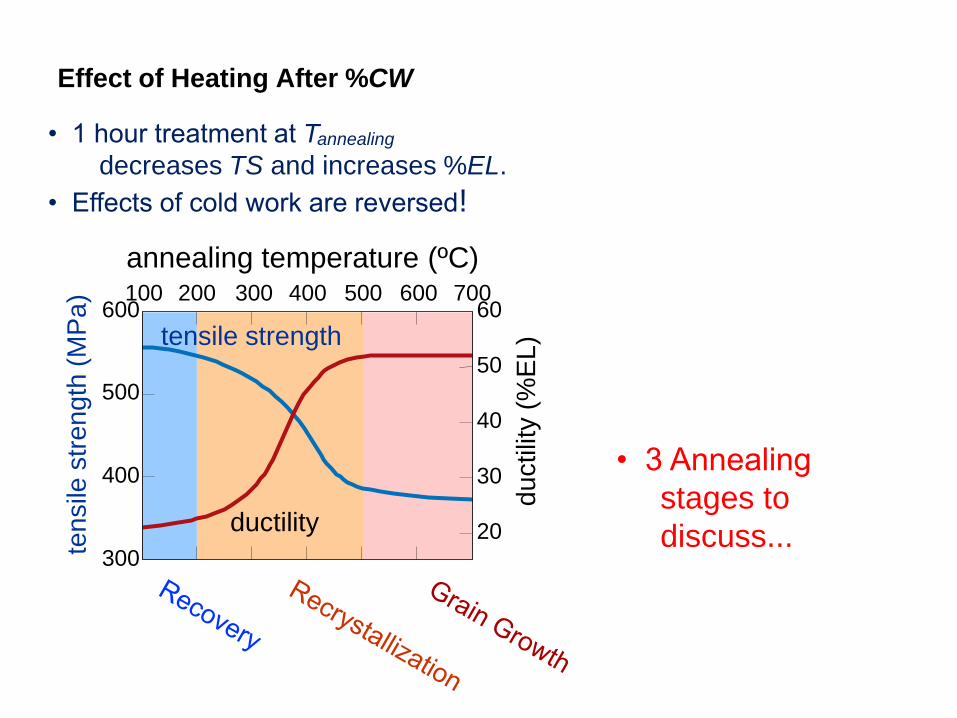
• 1 hour treatment at Tannealing
decreases TS and increases %EL.
• Effects of cold work are reversed!
• 3 Annealing
stages to
discuss...
Effect of Heating After %CW tensile
str
en
gth
(M
Pa)
du
ctilit
y (
%E
L) tensile strength
ductility
600
300
400
500
60
50
40
30
20
annealing temperature (ºC) 200 100 300 400 500 600 700

• New grains are formed that:
-- have a low dislocation density
-- are small
-- consume cold-worked grains
Adapted from
Fig. 7.21 (a),(b),
Callister 8e.
(Fig. 7.21 (a),(b)
are courtesy of
J.E. Burke,
General Electric
Company.)
33% cold
worked
brass
New crystals
nucleate after
3 sec. at 580C.
0.6 mm 0.6 mm
Recrystallization of Brass
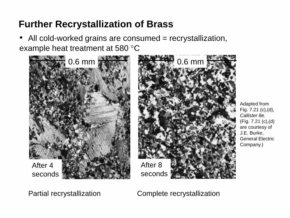
• All cold-worked grains are consumed = recrystallization,
example heat treatment at 580 °C
Adapted from
Fig. 7.21 (c),(d),
Callister 8e.
(Fig. 7.21 (c),(d)
are courtesy of
J.E. Burke,
General Electric
Company.)
After 4
seconds
After 8
seconds
0.6 mm 0.6 mm
Further Recrystallization of Brass
Partial recrystallization Complete recrystallization
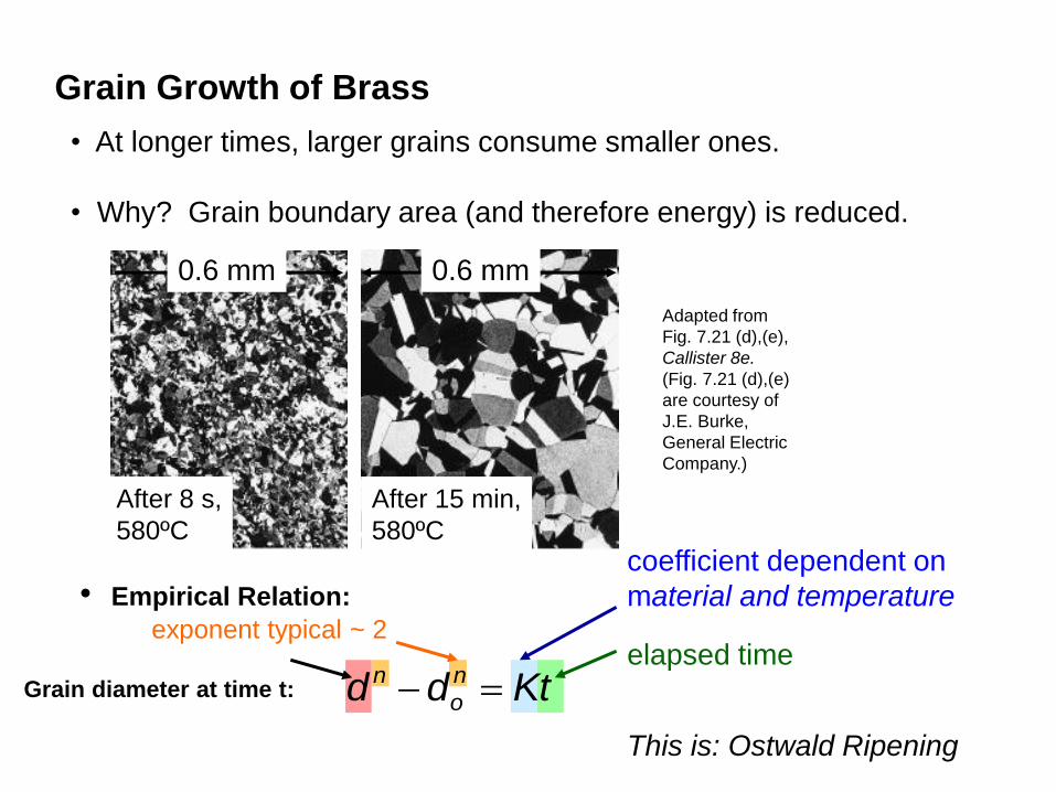
• At longer times, larger grains consume smaller ones.
• Why? Grain boundary area (and therefore energy) is reduced.
After 8 s,
580ºC
After 15 min,
580ºC
0.6 mm 0.6 mm
Adapted from
Fig. 7.21 (d),(e),
Callister 8e.
(Fig. 7.21 (d),(e)
are courtesy of
J.E. Burke,
General Electric
Company.)
Grain Growth of Brass
• Empirical Relation:
Ktdd n
o
n
coefficient dependent on
material and temperature
Grain diameter at time t:
elapsed time exponent typical ~ 2
This is: Ostwald Ripening

TR
Adapted from Fig.
7.22, Callister 8e.
º
º
TR = recrystallization
temperature

Recrystallization Temperature, TR
TR = recrystallization temperature = point of highest rate
of property change
1. TR 0.3-0.6 Tm (K)
2. Due to diffusion annealing time TR = f(t) shorter
annealing time => higher TR
3. Higher %CW => lower TR – strain hardening
4. Pure metals lower TR due to dislocation movements
• Easier to move in pure metals => lower TR

Coldwork Calculations
A cylindrical rod of brass originally 10,2 mm in diameter
is to be cold worked by drawing. The circular cross
section will be maintained during deformation. A cold-
worked tensile strength in excess of 380 MPa and a
ductility of at least 15 %EL are desired. Further more,
the final diameter must be 7,6 mm.
Explain how this may be accomplished.
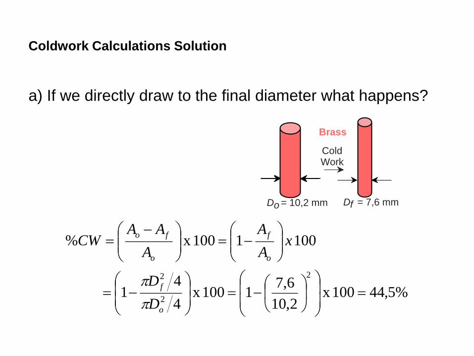
Coldwork Calculations Solution
a) If we directly draw to the final diameter what happens?
%5,44100 x 2,10
6,71100 x
4
41
100 1100 x %
2
2
2
o
f
o
f
o
fo
D
D
xA
A
A
AACW
D o = 10,2 mm
Brass
Cold Work
D f = 7,6 mm

Coldwork Calculation Solution:
• For %CW = 44,5%
540 420
– sy = 420 MPa
– TS = 540 MPa > 380 MPa
6
– %EL = 6 < 15% • This doesn’t satisfy criteria…… what can we do?
From Callister figure 7.19 – ed. 8

Coldwork Calculation Solution:
380
12
15
27
For %EL > 15
For TS > 380 MPa > 12 %CW
< 27 %CW
b) our working range is limited to %CW = 12 – 27%
From Callister figure 7.19 – ed. 8

This process Needs an Intermediate Recrystallization
i.e.: Cold draw-anneal-cold draw again
• For objective we need a cold work of %CW 12 - 27
– We’ll use %CW = 20
• Diameter after first cold draw (before 2nd cold draw)?
– must be calculated as follows:
2 2
2 2
2 2
2 2
%% 1 100 1
100
f f
s s
D D CWCW x
D D
0.5
2
2
%1
100
f
s
D CW
D
2
2 0.5%
1100
f
s
DD
CW
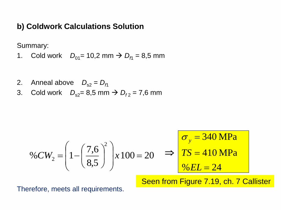
Summary:
1. Cold work D01= 10,2 mm Df1 = 8,5 mm
2. Anneal above Ds2 = Df1
3. Cold work Ds2= 8,5 mm Df 2 = 7,6 mm
Therefore, meets all requirements.
b) Coldwork Calculations Solution
20100 5,8
6,71%
2
2
xCW
24%
MPa 410
MPa 340
EL
TS
ys
Seen from Figure 7.19, ch. 7 Callister

• Dislocations are observed primarily in metals
and alloys.
• Strength is increased by making dislocation
motion difficult.
• Particular ways to increase strength are to:
--decrease grain size
--solid solution strengthening
--precipitate strengthening
--cold work
• Heating (annealing) can reduce dislocation density
and increase grain size. This decreases the strength.
Summary