chapter 6 steel design theory - · pdf filefatigue, and serviceability and constructibility...
TRANSCRIPT

BRIDGE DESIGN PRACTICE ● FEBRUARY 2015
Chapter 6 - Steel Design Theory 6-i
CHAPTER 6 STEEL DESIGN THEORY
TABLE OF CONTENTS
6.1 INTRODUCTION ............................................................................................................ 6-1
6.2 STRUCTURAL STEEL MATERIALS ........................................................................... 6-1
6.3 DESIGN LIMIT STATES ................................................................................................ 6-2
6.4 FLEXURE DESIGN ........................................................................................................ 6-2
6.4.1 Design Requirements ......................................................................................... 6-2
6.4.2 Composite Sections in Positive Flexure ............................................................. 6-4
6.4.3 Steel Sections ..................................................................................................... 6-9
6.5 SHEAR DESIGN ........................................................................................................... 6-13
6.5.1 Design Requirements ....................................................................................... 6-13
6.5.2 Nominal Shear Resistance ................................................................................ 6-13
6.5.3 Transverse Stiffeners ........................................................................................ 6-14
6.5.4 Shear Connectors .............................................................................................. 6-14
6.6 COMPRESSION DESIGN ............................................................................................ 6-15
6.6.1 Design Requirements ....................................................................................... 6-15
6.6.2 Axial Compressive Resistance ......................................................................... 6-16
6.7 TENSION DESIGN ....................................................................................................... 6-16
6.7.1 Design Requirements ....................................................................................... 6-16
6.7.2 Axial Tensile Resistance .................................................................................. 6-17
6.8 FATIGUE DESIGN ....................................................................................................... 6-18
6.9 SERVICEABILITY STATES ........................................................................................ 6-20
6.10 CONSTRUCTIBILITY .................................................................................................. 6-21
NOTATION ............................................................................................................................... 6-22
REFERENCES ........................................................................................................................... 6-26

BRIDGE DESIGN PRACTICE ● FEBRUARY 2015
Chapter 6 - Steel Design Theory 6-ii
This page is intentionally left blank.
BRIDGE DESIGN PRACTICE ● FEBRUARY 2015
Chapter 6 - Steel Design Theory 6-1
CHAPTER 6 STEEL DESIGN THEORY
6.1 INTRODUCTION
Steel has higher strength, ductility and toughness than many other structural materials such as concrete or wood, and thus makes a vital material for bridge structures. In this chapter, basic steel design concepts and requirements for I-sections specified in the AASHTO LRFD Bridge Design Specifications (AASHTO, 2012) and the California Amendments (Caltrans, 2014) for flexure, shear, compression, tension, fatigue, and serviceability and constructibility are discussed. Design considerations, procedure and example for steel plate girders will be presented in Chapter 9.
6.2 STRUCTURAL STEEL MATERIALS
AASHTO M 270 (Grade 36, 50, 50S, 50W, HPS 50W, HPS 70W and 100/100W) structural steels are commonly used for bridge structures. AASHTO material property standards differ from ASTM in notch toughness and weldability requirements. When these additional requirements are specified, ASTM A 709 steel is equivalent to AASHTO M 270 and is pre-qualified for use in welded steel bridges.
The use of ASTM A 709 Grade 50 for all structural steel, including flanges, webs, bearing stiffeners, intermediate stiffeners, cross frames, diaphragms and splice plates is preferred. The use of ASTM A 709 Grade 36 for secondary members will not reduce material unit costs. The use of ASTM A 709 Grade 100 or 100W steel is strongly discouraged. The hybrid section consisting of flanges with a higher yield strength than that of the web may be used to save materials and is becoming more promoted due to the new high performance steels. Using HPS 70W top and bottom flanges in negative moment regions and bottom flanges in positive moment regions and Grade 50 top flanges in positive moment regions, and Grade 50 for all webs may provide the most efficient hybrid girder.
The use of HPS (High Performance Steel) and weathering steel is encouraged if it is acceptable for the location. FHWA Technical Advisory T5140.22 (FHWA, 1989) provides guidelines on acceptable locations. In some situations, because of a particularly harsh environment, steel bridges must be painted. Although weathering steel will perform just as well as conventional steel in painted applications, it will not provide superior performance, and typically costs more than conventional steel. Therefore, specifying weathering steel in painted applications does not add value and should be avoided. HPS and weathering steel should not be used for the following conditions:
The atmosphere contains concentrated corrosive industrial or chemical fumes.
The steel is subject to heavy salt-water spray or salt-laden fog.

BRIDGE DESIGN PRACTICE ● FEBRUARY 2015
Chapter 6 - Steel Design Theory 6-2
The steel is in direct contact with timber decking, because timber retains moisture and may have been treated with corrosive preservatives.
The steel is used for a low urban-area overcrossing that will create a tunnel-like configuration over a road on which deicing salt is used. In these situations, road spray from traffic under the bridge causes salt to accumulate on the steel.
The location has inadequate air flow that does not allow adequate drying of the steel.
The location has very high rainfall and humidity or there is constant wetness.
There is low clearance (less than 8 to 10 ft) over stagnant or slow-moving waterways.
6.3 DESIGN LIMIT STATES
Steel girder bridges shall be designed to meet the requirements for all applicable limit states specified by AASHTO (2012) and California Amendments (Caltrans, 2014). For a typical steel girder bridges, Strength I and II, Service II, Fatigue and Constructibility are usually controlling limit states.
6.4 FLEXURE DESIGN 6.4.1 Design Requirements
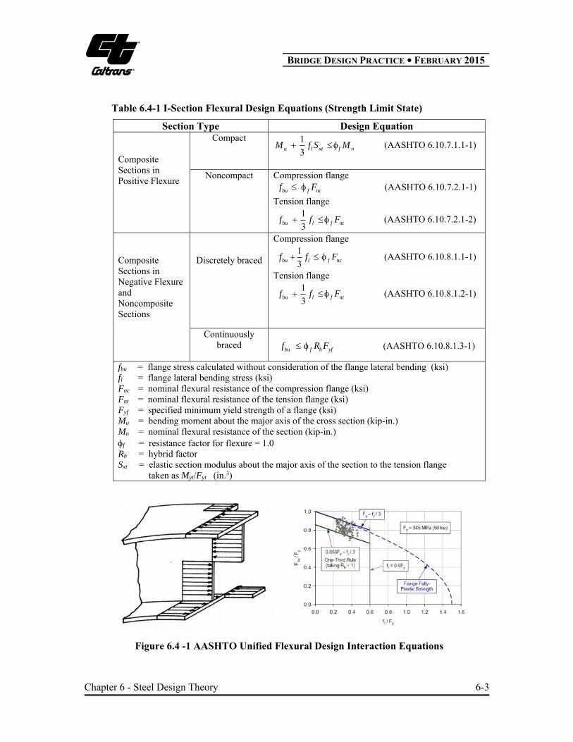
The AASHTO 6.10 and its Appendices A6 and B6 provide a unified flexural design approach for steel I-girders. The provisions combine major-axis bending, minor-axis bending and torsion into an interaction design formula and are applicable to straight bridges, horizontally curved bridges, or bridges combining both straight and curved segments. The AASHTO flexural design interaction equations for the strength limit state are summarized in Table 6.4-1. Those equations provide an accurate linear approximation of the equivalent beam-column resistance with the flange lateral bending stress less than 0.6Fy as shown in Figure 6.4-1 (White and Grubb 2005).
BRIDGE DESIGN PRACTICE ● FEBRUARY 2015
Chapter 6 - Steel Design Theory 6-3
Table 6.4-1 I-Section Flexural Design Equations (Strength Limit State)
Section Type Design Equation Composite Sections in Positive Flexure
Compact 1
3u l xt f nM f S M (AASHTO 6.10.7.1.1-1)
Noncompact Compression flange bu f ncf F (AASHTO 6.10.7.2.1-1)
Tension flange
1
3bu l f ntf f F (AASHTO 6.10.7.2.1-2)
Composite Sections in Negative Flexure and Noncomposite Sections
Discretely braced
Compression flange
1
3bu l f ncf f F (AASHTO 6.10.8.1.1-1)
Tension flange
1
3bu l f ntf f F (AASHTO 6.10.8.1.2-1)
Continuously braced
bu f h yff R F (AASHTO 6.10.8.1.3-1)
fbu = flange stress calculated without consideration of the flange lateral bending (ksi) fl = flange lateral bending stress (ksi) Fnc = nominal flexural resistance of the compression flange (ksi) Fnt = nominal flexural resistance of the tension flange (ksi) Fyf = specified minimum yield strength of a flange (ksi) Mu = bending moment about the major axis of the cross section (kip-in.) Mn = nominal flexural resistance of the section (kip-in.) f = resistance factor for flexure = 1.0 Rh = hybrid factor Sxt = elastic section modulus about the major axis of the section to the tension flange taken as Myt/Fyt (in.3)
Figure 6.4 -1 AASHTO Unified Flexural Design Interaction Equations

BRIDGE DESIGN PRACTICE ● FEBRUARY 2015
Chapter 6 - Steel Design Theory 6-4
For compact sections, since the nominal moment resistance is generally greater than the yield moment capacity, it is physically meaningful to design in terms of moment. For noncompact section, since the nominal resistance is limited to the yield strength, stress format is used. For composite I-sections in negative flexure and for noncomposite I-sections with compact or noncompact webs in straight bridges, when the web slenderness is well below the noncompact limit, the provisions specified in AASHTO Appendix 6A are encouraged to be used. However, when the web slenderness approaches the noncompact limit, Appendix 6A provides only minor increases in the nominal resistance.
6.4.2 Composite Sections in Positive Flexure
6.4.2.1 Nominal Flexural Resistance
At the strength limit state, the compression flange of composite sections in positive flexure is continuously supported by the concrete deck and lateral bending does not need to be considered. For compact sections, the flexural resistance is expressed in terms of moment, while for noncompact sections, the flexural resistance is expressed in terms of the elastically computed stress. The compact composite section shall meet the following requirements:
Straight bridges
70yfF ksi
150wt
D (AASHTO 6.10.2.1.1-1)
ycw
cp
F
E
t
D76.3
2 (AASHTO 6.10.6.2.2-1)
where Dcp is the web depth in compression at the plastic moment (in.); E is modulus of elasticity of steel (ksi); Fyc is specified minimum yield strength of a compression flange (ksi). Composite sections in positive flexure not satisfying one or more of above four requirements are classified as noncompact sections. The nominal flexural resistances are listed in Table 6.4-2.

BRIDGE DESIGN PRACTICE ● FEBRUARY 2015
Chapter 6 - Steel Design Theory 6-5
Table 6.4-2 Nominal Flexural Resistance for Composite Sections in Positive Flexure (Strength Limit State)
Section Type
Nominal Flexural Resistance
Compact
for 0.1
/ 0.1min 1 1 for 0.1
0.32
1.3 for a continous span
p p t
y p tn p p t
p
h y
M D D
M D DM M D D
M
R M
(AASHTO 6.10.7.1.2-1, 3) and (CA 6.10.7.1.2-2)
Noncompact Compression flange
ychbnc FRRF (AASHTO 6.10.7.2.2-1)
Tension flange
ythnt FRF (AASHTO 6.10.7.2.2-2)
Ductility Requirement
For both compact and noncompact sections
tp DD 42.0 (AASHTO 6.10.7.3-1)
Dp = distance from the top of the concrete deck to the neutral axis of the composite section at the plastic moment (in.) Dt = total depth of the composite section (in.) Fyt = specified minimum yield strength of a tension flange (ksi) Mp = plastic moment of the composite section (kip-in.) My = yield moment of the composite section (kip-in.) Rb = web load-shedding factor
6.4.2.2 Yield Moment
The yield moment My for a composite section in positive flexure is defined as the moment which causes the first yielding in one of the steel flanges. My is the sum of the moments applied separately to the appropriate sections, i.e., the steel section alone, the short-term composite section, and the long-term composite section. It is based on elastic section properties and can be expressed as:
y D1 D2 ADM M M M (AASHTO D6.2.2-2)
where MD1 is moment due to factored permanent loads applied to the steel section alone (kip-in.); MD2 is moment due to factored permanent loads such as wearing surface and barriers applied to the long-term composite section (kip-in.); MAD is additional live load moment to cause yielding in either steel flange applied to the short-term composite section and can be obtained from the following equation (kip-in.):
BRIDGE DESIGN PRACTICE ● FEBRUARY 2015
Chapter 6 - Steel Design Theory 6-6
ST
AD
LT
D
NC
Dyf S
M
S
M
S
MF 21 (AASHTO D6.2.2-1)
LT
D
NC
DyfSTAD S
M
S
MFSM 21 (6.4-1)
where SNC, SST and SLT are elastic section modulus for steel section alone, short-term composite and long-term composite sections, respectively (in.3).
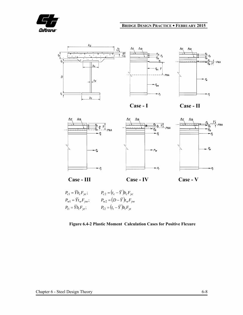
6.4.2.3 Plastic Moment
The plastic moment Mp for a composite section is defined as the moment which causes the yielding of the entire steel section and reinforcement and a uniform stress distribution of 0.85 f c
' in the compression concrete slab. f c' is minimum specified
28-day compressive strength of concrete. In positive flexure regions the contribution of reinforcement in the concrete slab is small and can be neglected. Table 6.4-3 summarizes calculations of Mp.

BRIDGE DESIGN PRACTICE ● FEBRUARY 2015
Chapter 6 - Steel Design Theory 6-7
Table 6.4-3 Plastic Moment Calculation
Regions Case and PNA Condition and Y Mp
I - In Web rtrbscwt PPPPPP
1
2 w
rbrtsct
P
PPPPPDY
MP
DY D Y
P d P d P d P d P d
pw
s s rt rt rb rb c c t t
2
2 2
II - In Top Flange
P P P P P Pt w c s rb rt
12 c
rbrtstwc
P
PPPPPtY
MP
tY t Y
P d P d P d P d P d
pc
cc
s s rt rt rb rb w w t t
2
2 2
Positive Figure 6.4.2
III- In Slab, Below Prb rtrbs
s
rbcwt PPP
t
CPPP
s
rbrttcws
P
PPPPPtY
ttwwccrbrbrtrt
s
sp
dPdPdPdPdP
t
PYM
2
2
IV - In Slab, Above Prb
Below Prt
rtss
rtrbcwt PP
t
CPPPP
s
rttwcrbs
P
PPPPPtY
ttwwccrbrbrtrt
s
sp
dPdPdPdPdP
t
PYM
2
2
V - In Slab, above Prt
ss
rtrtrbcwt P
t
CPPPPP
s
rttwcrbs
P
PPPPPtY
ttwwccrbrbrtrt
s
sp
dPdPdPdPdP
t
PYM
2
2
Negative Figure 6.4.3
I - In Web rtrbtwc PPPPP
1
2 w
rbrttc
P
PPPPDY
MP
DY D Y
P d P d Pd P d
pw
rt rt rb rb t t c c
2
2 2
II - In Top Flange
rtrbtwc PPPPP
12 t
rbrtcwt
P
PPPPtY
ccwwrbrbrtrt
tt
tp
dPdPdPdP
YtYt
PM
22
2
P F Art yrt rt ; sscs tbfP 85.0 ; rbyrbrb AFP ; P F b tc yc c t ; P F Dtw yw w ; P F b tt yt t t ;
cf = minimum specified 28-day compressive strength of concrete (ksi)
PNA = plastic neutral axis Arb, Art = reinforcement area of bottom and top layer in concrete deck slab (in.2) Fyrb, Fyrt = yield strength of reinforcement of bottom and top layers (ksi) bc, bt, bs = width of compression, tension steel flange and concrete deck slab (in.) tc, tt, tw, ts = thickness of compression, tension steel flange, web and concrete deck slab (in.) Fyt, Fyc, Fyw = yield strength of tension flange, compression flange and web (ksi)
BRIDGE DESIGN PRACTICE ● FEBRUARY 2015
Chapter 6 - Steel Design Theory 6-8
;1 yccc FbYP ycccc FbYtP 2
;1 ywww FtYP ywww FtYDP 2
;1 yttt FbYP ytttt FbYtP 2
Figure 6.4-2 Plastic Moment Calculation Cases for Positive Flexure
Case - III Case - IV Case - V
Case - I Case - II

BRIDGE DESIGN PRACTICE ● FEBRUARY 2015
Chapter 6 - Steel Design Theory 6-9
;1 ywww FtYP ywww FtYDP 2
;1 yttt FbYP ytttt FtYtP 2
Figure 6.4-3 Plastic Moment Calculation Cases for Negative Flexure
6.4.3 Steel Sections
The flexural resistance of a steel section (i.e., composite sections in negative flexure and noncomposite sections) is governed by three failure modes or limit states: yielding, flange local buckling and lateral-torsional buckling. The moment capacity depends on the yield strength of steel, the slenderness ratio of the compression flange, f in terms of width-to-thickness ratio (bfc/2tfc) for local buckling and the unbraced length Lb for lateral-torsional buckling. Figure 6.4-4 shows dimensions of a typical I-girder. Figures 6.4-5 and 6.4-6 show graphically the compression flange local and lateral torsional buckling resistances, respectively. Calculations for nominal flexural resistances are illustrated in Table 6.4-4.
For sections in straight bridges satisfying the following requirements:
70yfF ksi
ycw
c
F
E
t
D7.5
2 (AASHTO 6.10.6.2.3-1)
3.0yt
yc
I
I (AASHTO 6.10.6.2.3-2)
The flexural resistance in term of moments may be determined by AASHTO Appendix A6, and may exceed the yield moment.
Case - I Case - II

BRIDGE DESIGN PRACTICE ● FEBRUARY 2015
Chapter 6 - Steel Design Theory 6-10
Figure 6.4-4 Dimensions of a Typical I-Girder
Figure 6.4-5 I-Section Compression-Flange Flexural Local-Buckling Resistance
bftf
bt
tp

BRIDGE DESIGN PRACTICE ● FEBRUARY 2015
Chapter 6 - Steel Design Theory 6-11
Figure 6.4-6 I-Section Compression-Flange Flexural Torsional Resistance

BRIDGE DESIGN PRACTICE ● FEBRUARY 2015
Chapter 6 - Steel Design Theory 6-12
Table 6.4-4 Nominal Flexural Resistance for Steel Sections (Composite Sections in Negative Flexure and Noncomposite Section) (Strength Limit State) Flange Nominal Flexural Resistance Compression
],[smaller )()( LTBncFLBncnc FFF (AASHTO 6.10.8.2.1)
for
1 1 for
b h yc f pf
yr f pfnc FLBb h yc f pf
h yc rf pf
R R F
F FR R F
R F
(AASHTO 6.10.8.2.2-1 &2)
for
1 1 for
for
b h yc b p
yr b pb b h yc b h yc b p rnc LTB
h yc r p
cr b h yc b r
R R F L L
F L LF C R R F R R F L L L
R F L L
F R R F L L
(AASHTO 6.10.8.2.3-1, 2 &3) Tension ythnt FRF (AASHTO 6.10.8.3-1)
Lb = unbraced length of compression flange (in.)
yctychbp FErFRRL /0.1 achieve length to unbraced limiting (AASHTO 6.10.8.2.3-4)
yrtr FErL / yielding nominal ofonset theachieve length to unbraced limiting
(AASHTO 6.10.8.2.3-5)
fc
fcf t
b
2 flangen compressiofor ratio slenderess
(AASHTO 6.10.8.2.2-3)
ycpf F
E0.38 flangen compressiocompact afor ratio slenderess (AASHTO 6.10.8.2.2-4)
ycrf F
E0.56 flange noncompact afor ratio sslendernes limiting (AASHTO 6.10.8.2.2-5)
2
2elastic lateral torsional buckling stress (ksi)
/
b bcr
tb
C R EF
L r
(AASHTO 6.10.8.2.3-8)
ycywycyr FFFF 0.5 ,7.0smaller (AASHTO 6.10.8.2.2)
Cb = moment gradient modifier rt = effective radius of gyration for lateral torsional buckling (in.)

BRIDGE DESIGN PRACTICE ● FEBRUARY 2015
Chapter 6 - Steel Design Theory 6-13
6.5 SHEAR DESIGN 6.5.1 Design Requirements
For I-girder web panels, the following equation shall be satisfied.
u c nV V (AASHTO 6.10.9.1-1)
where Vu is factored shear at the section under consideration (kip); Vn is nominal shear resistance (kip) and c is resistance factor for shear = 1.0.
6.5.2 Nominal Shear Resistance
Similar to the flexural resistance, web shear resistance is also dependent on the slenderness ratio in terms of depth-to-thickness ratio (D/tw).
For the web without transverse stiffeners, shear resistance is provided by the beam action of shearing yield or elastic shear buckling. For end panels of stiffened webs adjacent to simple support, shear resistance is limited to the beam action only.
pcrn CVVV (AASHTO 6.10.9.2-1; 9.3-1)
wywp DtFV 58.0 (AASHTO 6.10.9.2-2)
40.1For/
57.1
40.112.1For/
12.1
12.1For0.1
2ywwyww
ywwywyww
yww
F
Ek
t
D
F
Ek
tD
F
Ek
t
D
F
Ek
F
Ek
tD
F
Ek
t
D
C
(AASHTO 6.10.9.3.2-4,5,6)
2)/(
55
Ddk
o
(AASHTO 6.10.9.3.2-7)
where do is transverse stiffener spacing (in.); C is ratio of the shear-buckling resistance to the shear yield strength; Vcr is shear-buckling resistance (kip) and Vp is plastic shear force (kip).
For interior web panels with transverse stiffeners, the shear resistance is provided by both the beam and the tension field actions as shown in Figure 6.5-1.

BRIDGE DESIGN PRACTICE ● FEBRUARY 2015
Chapter 6 - Steel Design Theory 6-14
Figure 6.5-1 Tension Field Action
For 5.22
ftftfcfc
w
tbtb
Dt (AASHTO 6.10.9.3.2-1)
2
1
187.0
D
d
CCVV
o
pn (AASHTO 6.10.9.3.2-2)
otherwise
D
d
D
d
CCVV
oo
pn2
1
187.0 (AASHTO 6.10.9.3.2-8)
where bfc and bft are full width of a compression and tension flange, respectively (in.); tfc and tft are thickness of a compression and tension flange, respectively (in.); tw is web thickness (in.) and do is transverse stiffener spacing (in.).
6.5.3 Transverse Stiffeners
Transverse intermediate stiffeners work as anchors for the tension field force so that post-buckling shear resistance can be developed. It should be noted that elastic web shear buckling cannot be prevented by transverse stiffeners. Transverse stiffeners are designed to (1) meet the slenderness requirement of projecting elements to prevent local buckling, (2) provide stiffness to allow the web to develop its post-buckling capacity, and (3) have strength to resist the vertical components of the diagonal stresses in the web.
6.5.4 Shear Connectors
To ensure a full composite action, shear connectors must be provided at the interface between the concrete slab and the steel to resist interface shear. Shear connectors are usually provided throughout the length of the bridge. If the longitudinal reinforcement in the deck slab is not considered in the composite

BRIDGE DESIGN PRACTICE ● FEBRUARY 2015
Chapter 6 - Steel Design Theory 6-15
section, shear connectors are not necessary in negative flexure regions. If the longitudinal reinforcement is included either additional connectors can be placed in the region of dead load contra-flexure points or they can be continued through the negative flexure region at maximum spacing. The fatigue and strength limit states must be considered in the shear connector design.
6.6 COMPRESSION DESIGN 6.6.1 Design Requirements
For axially loaded compression members, the following equation shall be satisfied:
Pu ≤ Pr = cPn (6.6-1)
where Pu is factored axial compression load (kip); Pr is factored axial compressive resistance (kip); Pn is nominal compressive resistance (kip) and c is resistance factor for compression = 0.9.
For members subjected to combined axial compression and flexure, the following interaction equation shall be satisfied:
For 2.0r
u
P
P
0.10.2
ry
uy
rx
ux
r
u
M
M
M
M
P
P (AASHTO 6.9.2.2-1)
For 2.0r
u
P
P
0.10.9
0.8
ry
uy
rx
ux
r
u
M
M
M
M
P
P (AASHTO 6.9.2.2-2)
where Mux and Muy are factored flexural moments (second-order moments) about the x-axis and y-axis, respectively (kip-in.); Mrx and Mry are factored flexural resistance about the x-axis and y-axis, respectively (kip-in.).
Compression members shall also meet the slenderness ratio requirements, Kl/r ≤ 120
for primary members, and Kl/r ≤ 140 for secondary members. K is effective length factor; l is unbraced length (in.) and r is minimum radius of gyration (in.).
BRIDGE DESIGN PRACTICE ● FEBRUARY 2015
Chapter 6 - Steel Design Theory 6-16
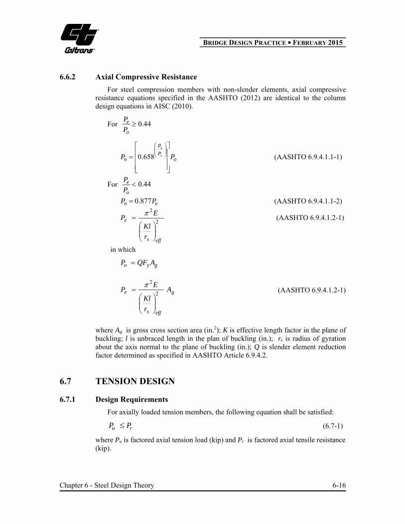
6.6.2 Axial Compressive Resistance
For steel compression members with non-slender elements, axial compressive resistance equations specified in the AASHTO (2012) are identical to the column design equations in AISC (2010).
For 44.0o
e
P
P
oP
P
n PP e
o
658.0 (AASHTO 6.9.4.1.1-1)
For 44.0o
e
P
P
en PP 877.0 (AASHTO 6.9.4.1.1-2)
2
2
effs
e
r
Kl
EP
(AASHTO 6.9.4.1.2-1)
in which
gyo AQFP
g
effs
e A
r
Kl
EP
2
2
(AASHTO 6.9.4.1.2-1)
where Ag is gross cross section area (in.2); K is effective length factor in the plane of buckling; l is unbraced length in the plan of buckling (in.); rs is radius of gyration about the axis normal to the plane of buckling (in.); Q is slender element reduction factor determined as specified in AASHTO Article 6.9.4.2.
6.7 TENSION DESIGN 6.7.1 Design Requirements
For axially loaded tension members, the following equation shall be satisfied:
ru PP (6.7-1)
where Pu is factored axial tension load (kip) and Pr is factored axial tensile resistance (kip).

BRIDGE DESIGN PRACTICE ● FEBRUARY 2015
Chapter 6 - Steel Design Theory 6-17
For members subjected to combined axial tension and flexure, the following interaction equation shall be satisfied:
For 2.0r
u
P
P
0.10.2
ry
uy
rx
ux
r
u
M
M
M
M
P
P (AASHTO 6.8.2.3-1)
For 2.0r
u
P
P
0.10.9
0.8
ry
uy
rx
ux
r
u
M
M
M
M
P
P (AASHTO 6.8.2.3-2)
where Mux and Muy are factored flexural moments about the x-axis and y-axis, respectively (kip-in.); Mrx and Mry are factored flexural resistance about the x-axis and y-axis, respectively (kip-in.).
Tension members shall also meet the slenderness ratio requirements, l/r ≤ 140 for primary members subjected to stress reversal, l/r ≤ 200 for primary members not subjected to stress reversal, and l/r ≤ 240 for secondary members.
6.7.2 Axial Tensile Resistance
For steel tension members, axial tensile resistance equations are smaller of yielding on the gross section and fracture on the net section as follows:
Yielding in gross section:
y yr ny y gP P F A (AASHTO 6.8.2.1-1)
Fracture in net section:
UAFPP nuunuur (AASHTO 6.8.2.1-2)
where Pny is nominal tensile for yielding in gross section (kip); Pnu is nominal tensile for fracture in net section (kip); An is net cross section area (in.2); Fu is specified minimum tensile strength (ksi); U is reduction factor to account for shear leg; y is resistance factor for yielding of tension member = 0.95; u is resistance factor for fracture of tension member = 0.8.

BRIDGE DESIGN PRACTICE ● FEBRUARY 2015
Chapter 6 - Steel Design Theory 6-18
6.8 FATIGUE DESIGN
There are two types of fatigue: load and distortion induced fatigue. The basic fatigue design requirement for load-induced fatigue is limiting live load stress range to fatigue resistance for each component and connection detail. Distortion-induced fatigue usually occurs at the web near a flange due to improper detailing. The design requirement for distortion-induced fatigue is to follow proper detailing practice to provide sufficient load paths. For load-induced fatigue consideration, the most common types of components and details in a typical I- girder are (AASHTO Table 6.6.1.2.3-1) listed in Table 6.8-1.
Table 6.8-1 I-Section Flexural Design Equations (Strength Limit State)
Type of Details
Category (AASHTO Table 6.6.1.2.3-1)
1 Base metal and weld metal at full-penetration groove-welded splices
B
2 Base metal at gross section of high-strength bolted slip-critical connections (bolt gusset to flange)
B
3 Base metal at fillet-welded stud- type shear connectors
C
4 Base metal at toe of transverse stiffener-to-flange and transverse stiffener-to-web welds
C
Nominal fatigue resistance as shown in Figure 6.8-1 (AASHTO, 2012) is calculated as follows:
For infinite fatigue life (N > NTH)
THn FF (AASHTO 6.1.2.5-1)
For finite fatigue life (N NTH)
3
1
N
AFn (AASHTO 6.6.1.2.5-2)
in which:
N = (365)(75)n(ADTT)SL (AASHTO 6.6.1.2.5-3)
3TH
TH
AN
F
(CA 6.6.1.2.3-2)

BRIDGE DESIGN PRACTICE ● FEBRUARY 2015
Chapter 6 - Steel Design Theory 6-19
Figure 6.8-1 Fatigue Resistance
where A is a constant depending on detail category as specified in AASHTO Table 6.6.1.2.5-1, and (F)TH is the constant-amplitude fatigue threshold taken from AASHTO Table 6.6.1.2.5-3. NTH is minimum number of stress cycles corresponding to constant-amplitude fatigue threshold, (F)TH, as listed in CA Table 6.6.1.2.3-2.
)(ADTTpADTTSL (AASHTO 3.6.1.4.2-1)
where p is fraction of truck traffic in a single lane (AASHTO Table 3.6.1.4.2-1) = 0.8 for three or more lanes traffic, N is the number of stress-range cycles per truck passage = 1.0 for the positive flexure region for span > 40 ft. (CA Table 6.6.1.2.5-2). ADTT is the number of trucks per day in one direction averaged over the design life and is specified in CA 3.6.1.4.2.
Fatigue I: ADTT = 2500, 8365 75 1.0 0.8 2500 0.5475 10 THN N
Fatigue II: ADTT = 20, 365 75 1.0 0.8 20 438,000 THN N
The nominal fatigue resistances for typical Detail Categories in an I-girder are summarized in Table 6.8-2.
Number of cycle N
Finite life -Fatigue IILower Traffic VolumeP9 Truck
Infinite Life - Fatigue I Higher Traffic Volume 1.75HL93 Truck
3/1
N
AFn
nF
3TH
THF
AN
THn FF
F
atig
ue
Res
ista
nce

BRIDGE DESIGN PRACTICE ● FEBRUARY 2015
Chapter 6 - Steel Design Theory 6-20
Table 6.8-2 Nominal Fatigue Resistance
Detail Category
Constant –A ( 108 )
(ksi3)
Fatigue II
3
1
N
AFn
(ksi)
Fatigue I
THn FF
(ksi)
B 120.0 30.15 16.0 C 44.0 21.58 10.0 C 44.0 21.58 12.0 E 11.0 13.59 4.5
6.9 SERVICEABILITY STATES The service limit state design is intended to control the elastic and permanent deformations, which would affect riding ability. For steel girder, vehicular live load deflection may be limited to L/800 by AASHTO 2.5.2.6.
Based on past successful practice of the overload check in the AASHTO Standard Specifications (AASHTO, 2002) to prevent the permanent deformation due to expected severe traffic loadings, AASHTO 6.10.4 requires that for SERVICE II load combination, flange stresses in positive and negative bending without considering flange lateral bending, ff shall meet the following requirements:
For the top steel flange of composite sections
yfhf FRf 95.0 (AASHTO 6.10.4.2.2-1)
For the bottom steel flange of composite sections
yfhl
f FRf
f 95.02 (AASHTO 6.10.4.2.2-2)
For both steel flanges of noncomposite sections
yfhl
f FRf
f 8.02 (AASHTO 6.10.4.2.2-3)
For compact composite sections in positive flexure in shored construction, longitudinal compressive stress in concrete deck without considering flange lateral bending, fc, shall not exceed cf 6.0 where cf is minimum specified 28-day
compressive strength of concrete (ksi).
Except for composite sections in positive flexure satisfying 150/ wtD without
longitudinal stiffeners, all sections shall satisfy
crwc Ff (AASHTO 6.10.4.2.2-4)
BRIDGE DESIGN PRACTICE ● FEBRUARY 2015
Chapter 6 - Steel Design Theory 6-21
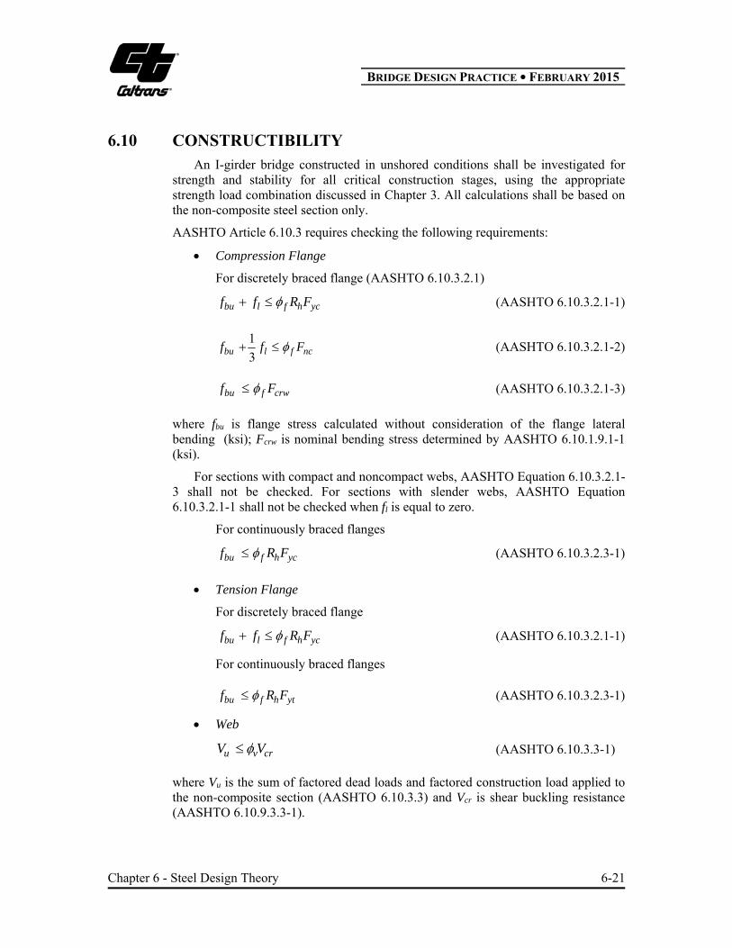
6.10 CONSTRUCTIBILITY An I-girder bridge constructed in unshored conditions shall be investigated for strength and stability for all critical construction stages, using the appropriate strength load combination discussed in Chapter 3. All calculations shall be based on the non-composite steel section only.
AASHTO Article 6.10.3 requires checking the following requirements:
Compression Flange
For discretely braced flange (AASHTO 6.10.3.2.1)
ychflbu FRff (AASHTO 6.10.3.2.1-1)
ncflbu Fff 3
1 (AASHTO 6.10.3.2.1-2)
crwfbu Ff (AASHTO 6.10.3.2.1-3)
where fbu is flange stress calculated without consideration of the flange lateral bending (ksi); Fcrw is nominal bending stress determined by AASHTO 6.10.1.9.1-1 (ksi).
For sections with compact and noncompact webs, AASHTO Equation 6.10.3.2.1-3 shall not be checked. For sections with slender webs, AASHTO Equation 6.10.3.2.1-1 shall not be checked when fl is equal to zero.
For continuously braced flanges
ychfbu FRf (AASHTO 6.10.3.2.3-1)
Tension Flange
For discretely braced flange
ychflbu FRff (AASHTO 6.10.3.2.1-1)
For continuously braced flanges
ythfbu FRf (AASHTO 6.10.3.2.3-1)
Web
crvu VV (AASHTO 6.10.3.3-1)
where Vu is the sum of factored dead loads and factored construction load applied to the non-composite section (AASHTO 6.10.3.3) and Vcr is shear buckling resistance (AASHTO 6.10.9.3.3-1).
BRIDGE DESIGN PRACTICE ● FEBRUARY 2015
Chapter 6 - Steel Design Theory 6-22
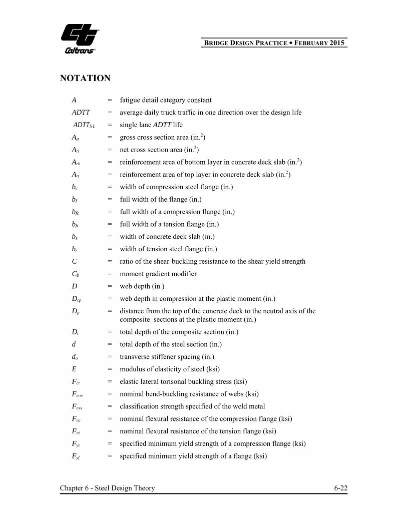
NOTATION
A = fatigue detail category constant
ADTT = average daily truck traffic in one direction over the design life
ADTTS L = single lane ADTT life
Ag = gross cross section area (in.2)
An = net cross section area (in.2)
Arb = reinforcement area of bottom layer in concrete deck slab (in.2)
Art = reinforcement area of top layer in concrete deck slab (in.2)
bc = width of compression steel flange (in.)
bf = full width of the flange (in.)
bfc = full width of a compression flange (in.)
bft = full width of a tension flange (in.)
bs = width of concrete deck slab (in.)
bt = width of tension steel flange (in.)
C = ratio of the shear-buckling resistance to the shear yield strength
Cb = moment gradient modifier
D = web depth (in.)
Dcp = web depth in compression at the plastic moment (in.)
Dp = distance from the top of the concrete deck to the neutral axis of the composite sections at the plastic moment (in.)
Dt = total depth of the composite section (in.)
d = total depth of the steel section (in.)
do = transverse stiffener spacing (in.)
E = modulus of elasticity of steel (ksi)
Fcr = elastic lateral torisonal buckling stress (ksi)
Fcrw = nominal bend-buckling resistance of webs (ksi)
Fexx = classification strength specified of the weld metal
Fnc = nominal flexural resistance of the compression flange (ksi)
Fnt = nominal flexural resistance of the tension flange (ksi)
Fyc = specified minimum yield strength of a compression flange (ksi)
Fyf = specified minimum yield strength of a flange (ksi)
BRIDGE DESIGN PRACTICE ● FEBRUARY 2015
Chapter 6 - Steel Design Theory 6-23
Fyr = compression-flange stress at the onset of nominal yielding including residual stress effects, taken as the smaller of 0.7Fyc and Fyw but not less than 0.5Fyc (ksi)
Fyrb = specified minimum yield strength of reinforcement of bottom layers (ksi)
Fyrt = specified minimum yield strength of reinforcement of top layers (ksi)
Fys = specified minimum yield strength of a stiffener (ksi)
Fyt = specified minimum yield strength of a tension flange (ksi)
Fyw = specified minimum yield strength of a web (ksi)
Fyu = specified minimum tensile strength of steel (ksi)
fbu = flange stress calculated without consideration of the flange lateral bending (ksi)
fc = longitudinal compressive stress in concrete deck without considering flange lateral bending (ksi)
ff = flange stresses without considering flange lateral bending (ksi)
fs = maximum flexural stress due to Service II at the extreme fiber of the flange (ksi)
fsr = fatigue stress range (ksi)
cf = minimum specified 28-day compressive strength of concrete (ksi)
I = moment of inertia of a cross section (in.4)
Iyc = moment of inertia of the compression flange about the vertical axis in the plane of web (in.4)
Iyt = moment of inertia of the tension flange about the vertical axis in the plane of web (in.4)
K = effective length factor of a compression member
L = span length (ft)
Lb = unbraced length of compression flange (in.)
Lp = limiting unbraced length to achieve RbRhFyc (in.)
Lr = limiting unbraced length to onset of nominal yielding (in.)
l = unbraced length of member (in.)
MAD = additional live load moment to cause yielding in either steel flange applied to the short-term composite section and can be obtained from the following equation (kip- in.)
MD1 = moment due to factored permanent loads applied to the steel section alone (kip-in.)

BRIDGE DESIGN PRACTICE ● FEBRUARY 2015
Chapter 6 - Steel Design Theory 6-24
MD2 = moment due to factored permanent loads such as wearing surface and barriers applied to the long-term composite section (kip-in.)
Mp = plastic moment (kip-in.)
Mn = nominal flexural resistance of the section (kip-in.)
Mrx, Mry = factored flexural resistance about the x-axis and y-axis, respectively (kip-in.)
Mu = bending moment about the major axis of the cross section (kip-in.)
Mux, Muy = factored flexural moments about the x-axis and y-axis, respectively (kip-in.)
My = yield moment (kip-in.)
N = number of cycles of stress ranges
NTH = minimum number of stress cycles corresponding to constant-amplitude fatigue threshold, (F)TH
n = number of stress-range cycles per truck passage
Pu = factored axial load (kip)
Pr = factored axial resistance (kip)
p = fraction of truck traffic in a single lane
Q = slender element reduction factor
Rh = hybrid factor
Rb = web load-shedding factor
R = radius of gyration
rt = effective radius of gyration for lateral torsional buckling (in.)
SLT = elastic section modulus for long-term composite sections, respectively (in.3)
SNC = elastic section modulus for steel section alone (in.3)
SST = elastic section modulus for short-term composite section (in.3)
Sxt = elastic section modulus about the major axis of the section to the tension flange taken as Myt/Fyt (in.3)
tc = thickness of compression steel flange (in.)
tf = thickness of the flange (in.)
tfc = thickness of a compression flange (in.)
tft = thickness of a tension flange (in.)
tt = thickness of tension steel flange (in.)
tw = thickness of web (in.)
ts = thickness of concrete deck slab (in.)
Vcr = shear-buckling resistance (kip)
BRIDGE DESIGN PRACTICE ● FEBRUARY 2015
Chapter 6 - Steel Design Theory 6-25
Vn = nominal shear resistance (kip)
Vp = plastic shear force (kip)
Vu = factored shear (kip)
f = slenderness ratio for compression flange = bfc/2tfc
pf = limiting slenderness ratio for a compact flange
rf = limiting slenderness ratio for a noncompact flange
(F)TH = constant-amplitude fatigue threshold (ksi)
(F)n = fatigue resistance (ksi)
f = resistance factor for flexure = 1.0
v = resistance factor for shear = 1.0
c = resistance factor for axial compression = 0.9
u = resistance factor for tension, fracture in net section = 0.8
y = resistance factor for tension, yielding in gross section = 0.95

BRIDGE DESIGN PRACTICE ● FEBRUARY 2015
Chapter 6 - Steel Design Theory 6-26
REFERENCES
1. AASHTO, (2012). AASHTO LRFD Bridge Design Specifications, Customary U.S. Unit (6th Edition), American Association of State Highway and Transportation Officials, Washington, DC.
2. AASHTO, (2002). Standard Specifications for Highway Bridges, 17th Edition,
American Association of State Highway and Transportation Officials, Washington, DC.
3. AISC, (2010). Specifications for Structural Steel Buildings, ANSI/AISC 360-10, American Institute of Steel Construction, Chicago, IL.
4. Caltrans, (2014). California Amendment to AASHTO LRFD Bridge Design Specifications
– 6th Edition, California Department of Transportation, Sacramento, CA.
5. FHWA, (1989). Technical Advisory T5140.22, Federal Highway Administration, Washington, DC.
6. White, D. W., and Grubb, M. A., (2005). “Unified Resistance Equation for Design of
Curved and Tangent Steel Bridge I-Girders.” Proceedings of the 2005 TRB Bridge Engineering Conference, Transportation Research Board, Washington, DC.