chapter 5: ethernetvapenik.s.cnl.sk/pcsiete/ccna1/05_ethernet.pdf · digit than as four binary...
TRANSCRIPT
Chapter 5: Ethernet
CCNA Routing and Switching
Introduction to Networks v6.0
2 © 2016 Cisco and/or its affiliates. All rights reserved. Cisco Confidential
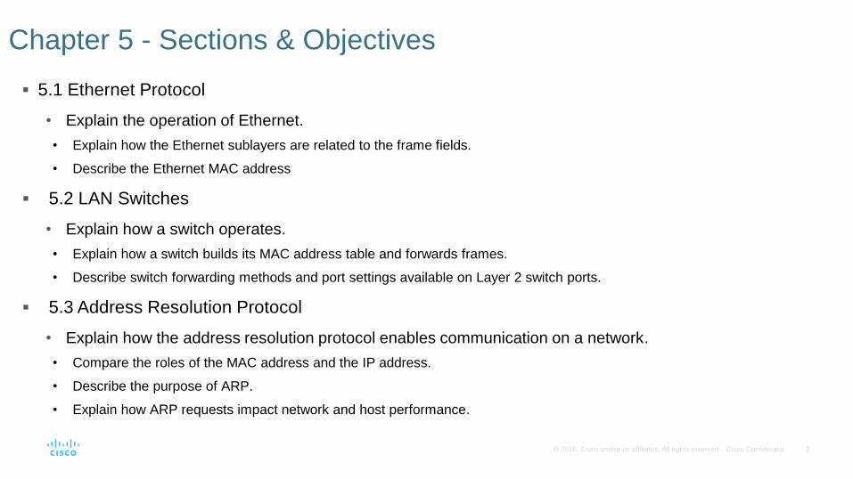
5.1 Ethernet Protocol
• Explain the operation of Ethernet.
• Explain how the Ethernet sublayers are related to the frame fields.
• Describe the Ethernet MAC address
5.2 LAN Switches
• Explain how a switch operates.
• Explain how a switch builds its MAC address table and forwards frames.
• Describe switch forwarding methods and port settings available on Layer 2 switch ports.
5.3 Address Resolution Protocol
• Explain how the address resolution protocol enables communication on a network.
• Compare the roles of the MAC address and the IP address.
• Describe the purpose of ARP.
• Explain how ARP requests impact network and host performance.
Chapter 5 - Sections & Objectives
3 © 2016 Cisco and/or its affiliates. All rights reserved. Cisco Confidential
5.1 Ethernet Protocol
4 © 2016 Cisco and/or its affiliates. All rights reserved. Cisco Confidential
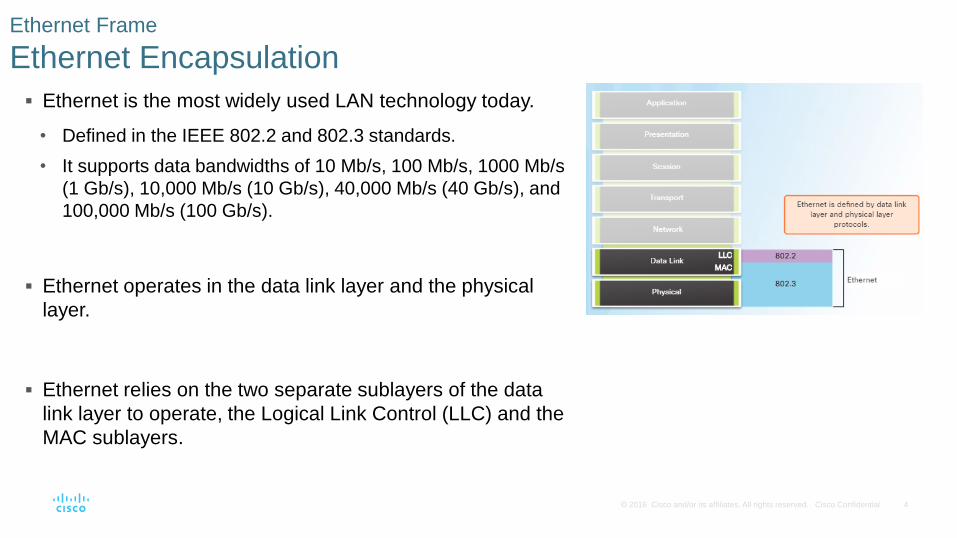
Ethernet is the most widely used LAN technology today.
• Defined in the IEEE 802.2 and 802.3 standards.
• It supports data bandwidths of 10 Mb/s, 100 Mb/s, 1000 Mb/s
(1 Gb/s), 10,000 Mb/s (10 Gb/s), 40,000 Mb/s (40 Gb/s), and
100,000 Mb/s (100 Gb/s).
Ethernet operates in the data link layer and the physical
layer.
Ethernet relies on the two separate sublayers of the data
link layer to operate, the Logical Link Control (LLC) and the
MAC sublayers.
Ethernet Frame
Ethernet Encapsulation
5 © 2016 Cisco and/or its affiliates. All rights reserved. Cisco Confidential
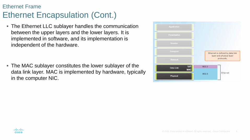
The Ethernet LLC sublayer handles the communication
between the upper layers and the lower layers. It is
implemented in software, and its implementation is
independent of the hardware.
The MAC sublayer constitutes the lower sublayer of the
data link layer. MAC is implemented by hardware, typically
in the computer NIC.
Ethernet Frame
Ethernet Encapsulation (Cont.)
6 © 2016 Cisco and/or its affiliates. All rights reserved. Cisco Confidential
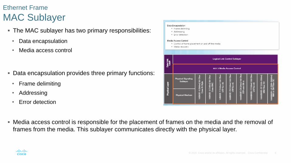
The MAC sublayer has two primary responsibilities:
• Data encapsulation
• Media access control
Data encapsulation provides three primary functions:
• Frame delimiting
• Addressing
• Error detection
Ethernet Frame
MAC Sublayer
Media access control is responsible for the placement of frames on the media and the removal of
frames from the media. This sublayer communicates directly with the physical layer.
7 © 2016 Cisco and/or its affiliates. All rights reserved. Cisco Confidential
Since 1973, Ethernet standards have evolved specifying faster and more flexible versions of the
technology.
Early versions of Ethernet were relatively slow at 10 Mbps.
The latest versions of Ethernet operate at 10 Gigabits per second and faster.
Ethernet Frame
Ethernet Evolution
8 © 2016 Cisco and/or its affiliates. All rights reserved. Cisco Confidential
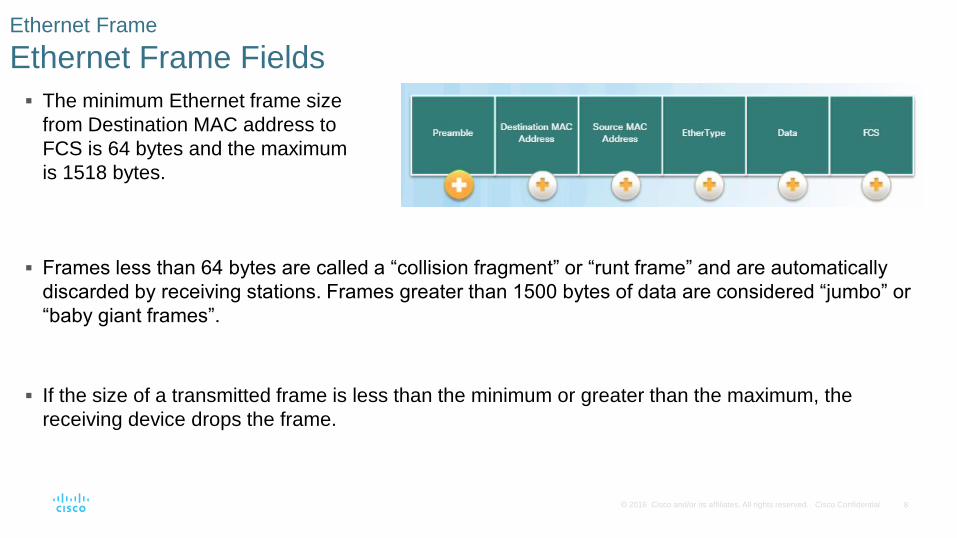
The minimum Ethernet frame size
from Destination MAC address to
FCS is 64 bytes and the maximum
is 1518 bytes.
Ethernet Frame
Ethernet Frame Fields
Frames less than 64 bytes are called a “collision fragment” or “runt frame” and are automatically
discarded by receiving stations. Frames greater than 1500 bytes of data are considered “jumbo” or
“baby giant frames”.
If the size of a transmitted frame is less than the minimum or greater than the maximum, the
receiving device drops the frame.
9 © 2016 Cisco and/or its affiliates. All rights reserved. Cisco Confidential
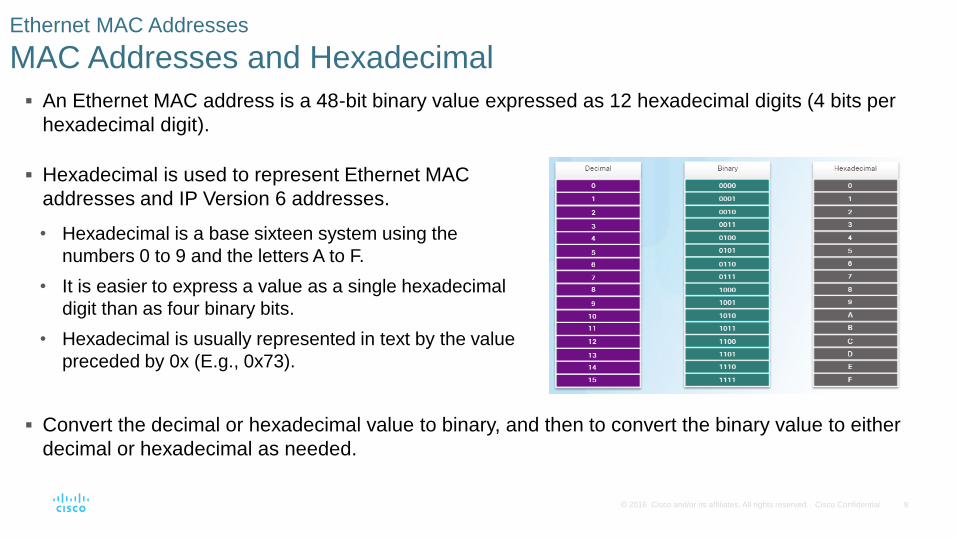
An Ethernet MAC address is a 48-bit binary value expressed as 12 hexadecimal digits (4 bits per
hexadecimal digit).
Ethernet MAC Addresses
MAC Addresses and Hexadecimal
Hexadecimal is used to represent Ethernet MAC
addresses and IP Version 6 addresses.
• Hexadecimal is a base sixteen system using the
numbers 0 to 9 and the letters A to F.
• It is easier to express a value as a single hexadecimal
digit than as four binary bits.
• Hexadecimal is usually represented in text by the value
preceded by 0x (E.g., 0x73).
Convert the decimal or hexadecimal value to binary, and then to convert the binary value to either
decimal or hexadecimal as needed.
10 © 2016 Cisco and/or its affiliates. All rights reserved. Cisco Confidential
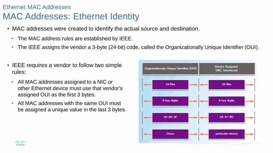
MAC addresses were created to identify the actual source and destination.
• The MAC address rules are established by IEEE.
• The IEEE assigns the vendor a 3-byte (24-bit) code, called the Organizationally Unique Identifier (OUI).
Ethernet MAC Addresses
MAC Addresses: Ethernet Identity
IEEE requires a vendor to follow two simple
rules:
• All MAC addresses assigned to a NIC or
other Ethernet device must use that vendor's
assigned OUI as the first 3 bytes.
• All MAC addresses with the same OUI must
be assigned a unique value in the last 3 bytes.

11 © 2016 Cisco and/or its affiliates. All rights reserved. Cisco Confidential
The MAC address is often referred to as a burned-in address (BIA) meaning the address is
encoded into the ROM chip permanently. When the computer starts up, the first thing the NIC does
is copy the MAC address from ROM into RAM.
Ethernet MAC Addresses
Frame Processing
When a device is forwarding a message to an
Ethernet network, it attaches header
information to the frame.
The header information contains the source
and destination MAC address.
12 © 2016 Cisco and/or its affiliates. All rights reserved. Cisco Confidential
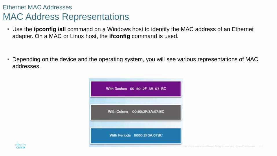
Use the ipconfig /all command on a Windows host to identify the MAC address of an Ethernet
adapter. On a MAC or Linux host, the ifconfig command is used.
Depending on the device and the operating system, you will see various representations of MAC
addresses.
Ethernet MAC Addresses
MAC Address Representations
13 © 2016 Cisco and/or its affiliates. All rights reserved. Cisco Confidential
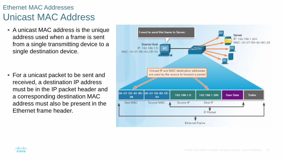
A unicast MAC address is the unique
address used when a frame is sent
from a single transmitting device to a
single destination device.
For a unicast packet to be sent and
received, a destination IP address
must be in the IP packet header and
a corresponding destination MAC
address must also be present in the
Ethernet frame header.
Ethernet MAC Addresses
Unicast MAC Address
14 © 2016 Cisco and/or its affiliates. All rights reserved. Cisco Confidential
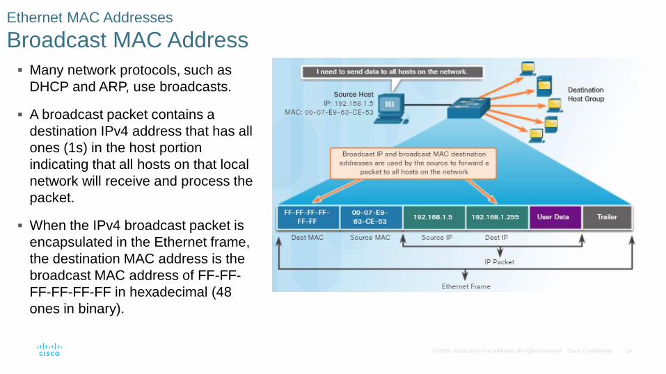
Many network protocols, such as
DHCP and ARP, use broadcasts.
A broadcast packet contains a
destination IPv4 address that has all
ones (1s) in the host portion
indicating that all hosts on that local
network will receive and process the
packet.
When the IPv4 broadcast packet is
encapsulated in the Ethernet frame,
the destination MAC address is the
broadcast MAC address of FF-FF-
FF-FF-FF-FF in hexadecimal (48
ones in binary).
Ethernet MAC Addresses
Broadcast MAC Address
15 © 2016 Cisco and/or its affiliates. All rights reserved. Cisco Confidential
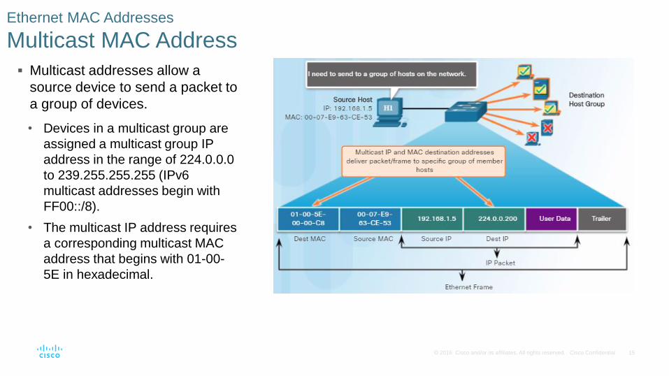
Multicast addresses allow a
source device to send a packet to
a group of devices.
• Devices in a multicast group are
assigned a multicast group IP
address in the range of 224.0.0.0
to 239.255.255.255 (IPv6
multicast addresses begin with
FF00::/8).
• The multicast IP address requires
a corresponding multicast MAC
address that begins with 01-00-
5E in hexadecimal.
Ethernet MAC Addresses
Multicast MAC Address
16 © 2016 Cisco and/or its affiliates. All rights reserved. Cisco Confidential
5.2 LAN Switches
17 © 2016 Cisco and/or its affiliates. All rights reserved. Cisco Confidential
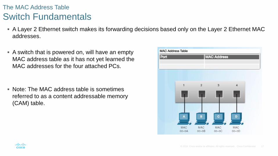
A Layer 2 Ethernet switch makes its forwarding decisions based only on the Layer 2 Ethernet MAC
addresses.
The MAC Address Table
Switch Fundamentals
A switch that is powered on, will have an empty
MAC address table as it has not yet learned the
MAC addresses for the four attached PCs.
Note: The MAC address table is sometimes
referred to as a content addressable memory
(CAM) table.
18 © 2016 Cisco and/or its affiliates. All rights reserved. Cisco Confidential
The switch dynamically builds the MAC
address table. The process to learn the
Source MAC Address is:
• Switches examine all incoming frames for
new source MAC address information to
learn.
• If the source MAC address is unknown, it
is added to the table along with the port
number.
• If the source MAC address does exist, the
switch updates the refresh timer for that
entry.
• By default, most Ethernet switches keep
an entry in the table for 5 minutes.
The MAC Address Table
Learning MAC Addresses
Switching Process Description
Learn Examining the Source
MAC Address
• Switches examine all incoming frames for new source MAC address information to learn.
• If the source MAC address is unknown, it is added to the table along with the port number.
• If the source MAC address does exist, the switch updates the refresh timer for that entry.
• By default, most Ethernet switches keep an entry in the table for 5 minutes.
Forward Examining the Destination
MAC Address
• If the destination MAC address is a broadcast or a multicast, the frame is also flooded out
all ports except the incoming port.
• If the destination MAC address is a unicast address, the switch will look for a match in its
MAC address table. • If the destination MAC address is in the table, it will forward the frame out the specified port.
• If the destination MAC address is not in the table (i.e., an unknown unicast) the switch will
forward the frame out all ports except the incoming port.
19 © 2016 Cisco and/or its affiliates. All rights reserved. Cisco Confidential
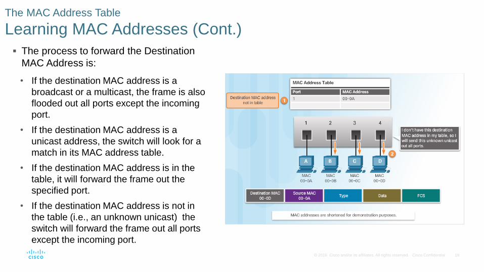
The process to forward the Destination
MAC Address is:
• If the destination MAC address is a
broadcast or a multicast, the frame is also
flooded out all ports except the incoming
port.
• If the destination MAC address is a
unicast address, the switch will look for a
match in its MAC address table.
• If the destination MAC address is in the
table, it will forward the frame out the
specified port.
• If the destination MAC address is not in
the table (i.e., an unknown unicast) the
switch will forward the frame out all ports
except the incoming port.
The MAC Address Table
Learning MAC Addresses (Cont.)
20 © 2016 Cisco and/or its affiliates. All rights reserved. Cisco Confidential
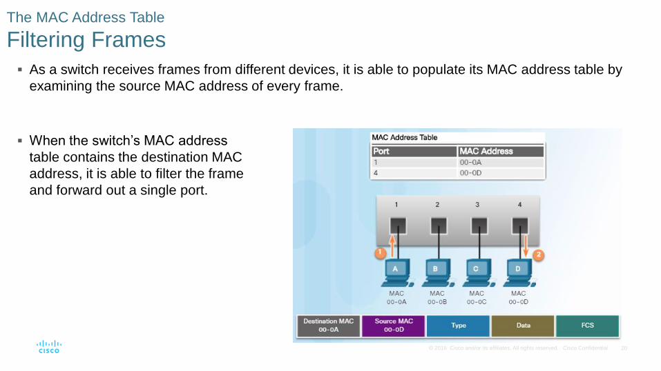
As a switch receives frames from different devices, it is able to populate its MAC address table by
examining the source MAC address of every frame.
The MAC Address Table
Filtering Frames
When the switch’s MAC address
table contains the destination MAC
address, it is able to filter the frame
and forward out a single port.
21 © 2016 Cisco and/or its affiliates. All rights reserved. Cisco Confidential
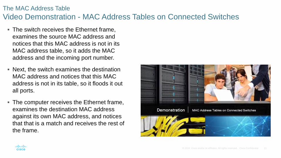
The switch receives the Ethernet frame,
examines the source MAC address and
notices that this MAC address is not in its
MAC address table, so it adds the MAC
address and the incoming port number.
Next, the switch examines the destination
MAC address and notices that this MAC
address is not in its table, so it floods it out
all ports.
The computer receives the Ethernet frame,
examines the destination MAC address
against its own MAC address, and notices
that that is a match and receives the rest of
the frame.
The MAC Address Table
Video Demonstration - MAC Address Tables on Connected Switches
22 © 2016 Cisco and/or its affiliates. All rights reserved. Cisco Confidential
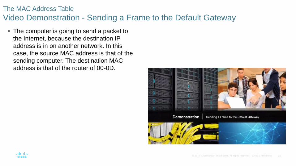
The computer is going to send a packet to
the Internet, because the destination IP
address is in on another network. In this
case, the source MAC address is that of the
sending computer. The destination MAC
address is that of the router of 00-0D.
The MAC Address Table
Video Demonstration - Sending a Frame to the Default Gateway

23 © 2016 Cisco and/or its affiliates. All rights reserved. Cisco Confidential
Switches use one of the following forwarding methods for switching data between network ports:
Switch Forwarding Methods
Frame Forwarding Methods on Cisco Switches
24 © 2016 Cisco and/or its affiliates. All rights reserved. Cisco Confidential
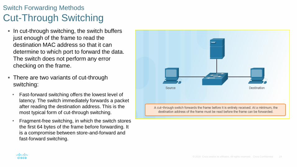
In cut-through switching, the switch buffers
just enough of the frame to read the
destination MAC address so that it can
determine to which port to forward the data.
The switch does not perform any error
checking on the frame.
There are two variants of cut-through
switching:
• Fast-forward switching offers the lowest level of
latency. The switch immediately forwards a packet
after reading the destination address. This is the
most typical form of cut-through switching.
• Fragment-free switching, in which the switch stores
the first 64 bytes of the frame before forwarding. It
is a compromise between store-and-forward and
fast-forward switching.
Switch Forwarding Methods
Cut-Through Switching
25 © 2016 Cisco and/or its affiliates. All rights reserved. Cisco Confidential
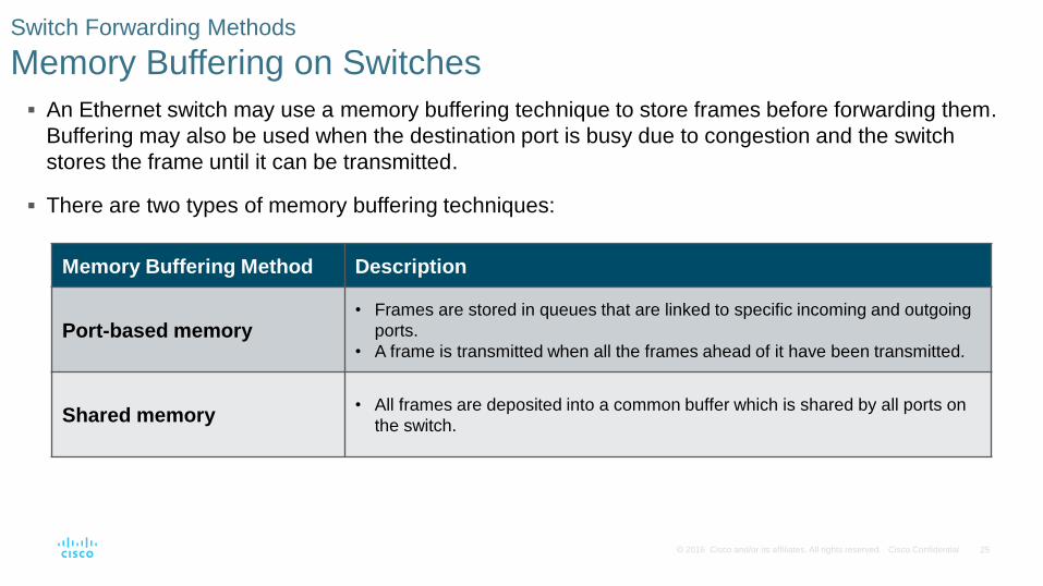
An Ethernet switch may use a memory buffering technique to store frames before forwarding them.
Buffering may also be used when the destination port is busy due to congestion and the switch
stores the frame until it can be transmitted.
There are two types of memory buffering techniques:
Switch Forwarding Methods
Memory Buffering on Switches
Memory Buffering Method Description
Port-based memory • Frames are stored in queues that are linked to specific incoming and outgoing
ports.
• A frame is transmitted when all the frames ahead of it have been transmitted.
Shared memory • All frames are deposited into a common buffer which is shared by all ports on
the switch.
26 © 2016 Cisco and/or its affiliates. All rights reserved. Cisco Confidential
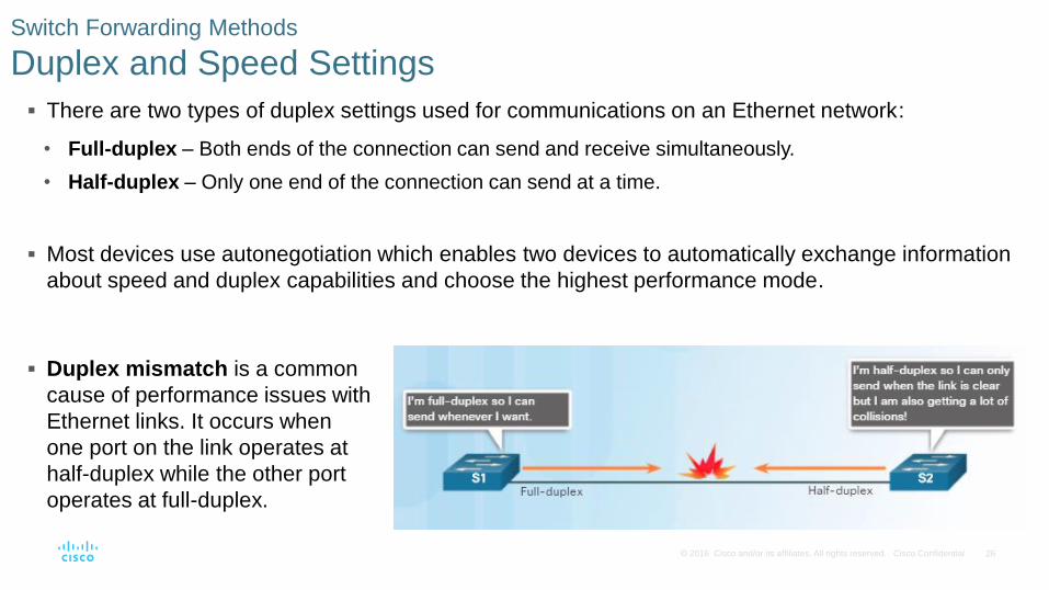
There are two types of duplex settings used for communications on an Ethernet network:
• Full-duplex – Both ends of the connection can send and receive simultaneously.
• Half-duplex – Only one end of the connection can send at a time.
Most devices use autonegotiation which enables two devices to automatically exchange information
about speed and duplex capabilities and choose the highest performance mode.
Switch Forwarding Methods
Duplex and Speed Settings
Duplex mismatch is a common
cause of performance issues with
Ethernet links. It occurs when
one port on the link operates at
half-duplex while the other port
operates at full-duplex.
27 © 2016 Cisco and/or its affiliates. All rights reserved. Cisco Confidential
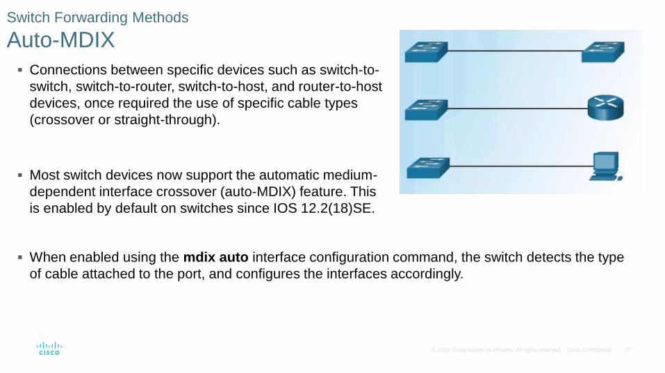
Connections between specific devices such as switch-to-
switch, switch-to-router, switch-to-host, and router-to-host
devices, once required the use of specific cable types
(crossover or straight-through).
Most switch devices now support the automatic medium-
dependent interface crossover (auto-MDIX) feature. This
is enabled by default on switches since IOS 12.2(18)SE.
Switch Forwarding Methods
Auto-MDIX
When enabled using the mdix auto interface configuration command, the switch detects the type
of cable attached to the port, and configures the interfaces accordingly.
28 © 2016 Cisco and/or its affiliates. All rights reserved. Cisco Confidential
5.3 Address Resolution Protocol
29 © 2016 Cisco and/or its affiliates. All rights reserved. Cisco Confidential
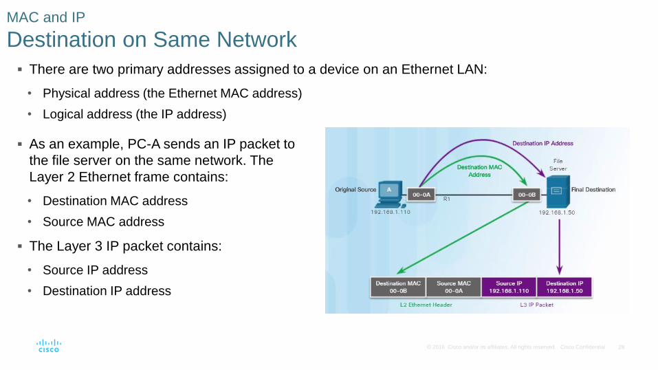
There are two primary addresses assigned to a device on an Ethernet LAN:
• Physical address (the Ethernet MAC address)
• Logical address (the IP address)
MAC and IP
Destination on Same Network
As an example, PC-A sends an IP packet to
the file server on the same network. The
Layer 2 Ethernet frame contains:
• Destination MAC address
• Source MAC address
The Layer 3 IP packet contains:
• Source IP address
• Destination IP address
30 © 2016 Cisco and/or its affiliates. All rights reserved. Cisco Confidential
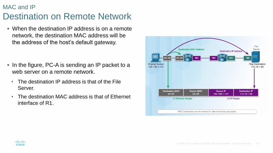
When the destination IP address is on a remote
network, the destination MAC address will be
the address of the host’s default gateway.
In the figure, PC-A is sending an IP packet to a
web server on a remote network.
• The destination IP address is that of the File
Server.
• The destination MAC address is that of Ethernet
interface of R1.
MAC and IP
Destination on Remote Network
31 © 2016 Cisco and/or its affiliates. All rights reserved. Cisco Confidential
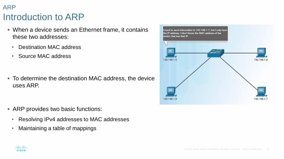
When a device sends an Ethernet frame, it contains
these two addresses:
• Destination MAC address
• Source MAC address
To determine the destination MAC address, the device
uses ARP.
ARP provides two basic functions:
• Resolving IPv4 addresses to MAC addresses
• Maintaining a table of mappings
ARP
Introduction to ARP
32 © 2016 Cisco and/or its affiliates. All rights reserved. Cisco Confidential
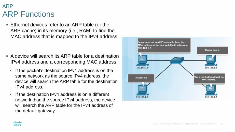
Ethernet devices refer to an ARP table (or the
ARP cache) in its memory (i.e., RAM) to find the
MAC address that is mapped to the IPv4 address.
A device will search its ARP table for a destination
IPv4 address and a corresponding MAC address.
• If the packet’s destination IPv4 address is on the
same network as the source IPv4 address, the
device will search the ARP table for the destination
IPv4 address.
• If the destination IPv4 address is on a different
network than the source IPv4 address, the device
will search the ARP table for the IPv4 address of
the default gateway.
ARP
ARP Functions
33 © 2016 Cisco and/or its affiliates. All rights reserved. Cisco Confidential
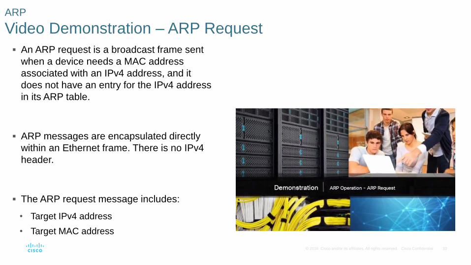
An ARP request is a broadcast frame sent
when a device needs a MAC address
associated with an IPv4 address, and it
does not have an entry for the IPv4 address
in its ARP table.
ARP messages are encapsulated directly
within an Ethernet frame. There is no IPv4
header.
The ARP request message includes:
• Target IPv4 address
• Target MAC address
ARP
Video Demonstration – ARP Request
34 © 2016 Cisco and/or its affiliates. All rights reserved. Cisco Confidential
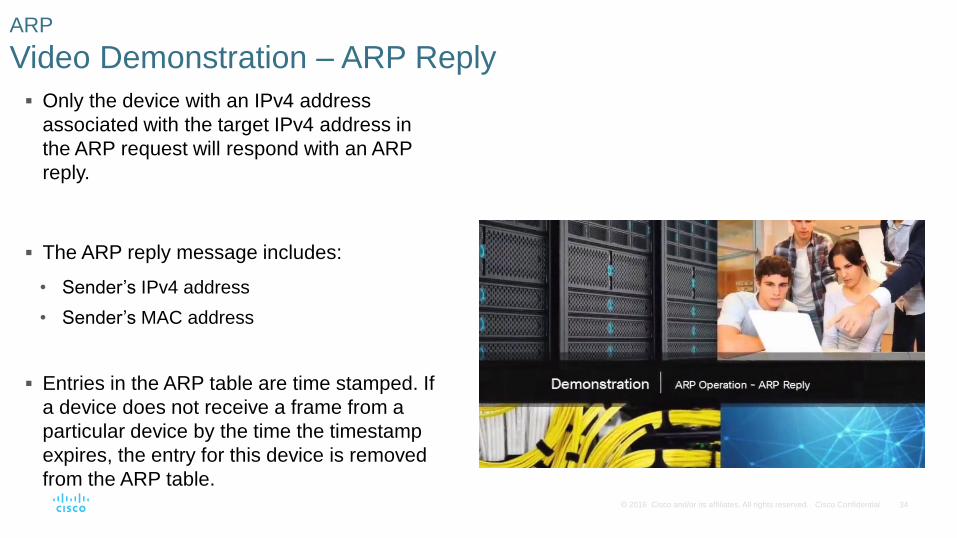
Only the device with an IPv4 address
associated with the target IPv4 address in
the ARP request will respond with an ARP
reply.
The ARP reply message includes:
• Sender’s IPv4 address
• Sender’s MAC address
Entries in the ARP table are time stamped. If
a device does not receive a frame from a
particular device by the time the timestamp
expires, the entry for this device is removed
from the ARP table.
ARP
Video Demonstration – ARP Reply
35 © 2016 Cisco and/or its affiliates. All rights reserved. Cisco Confidential
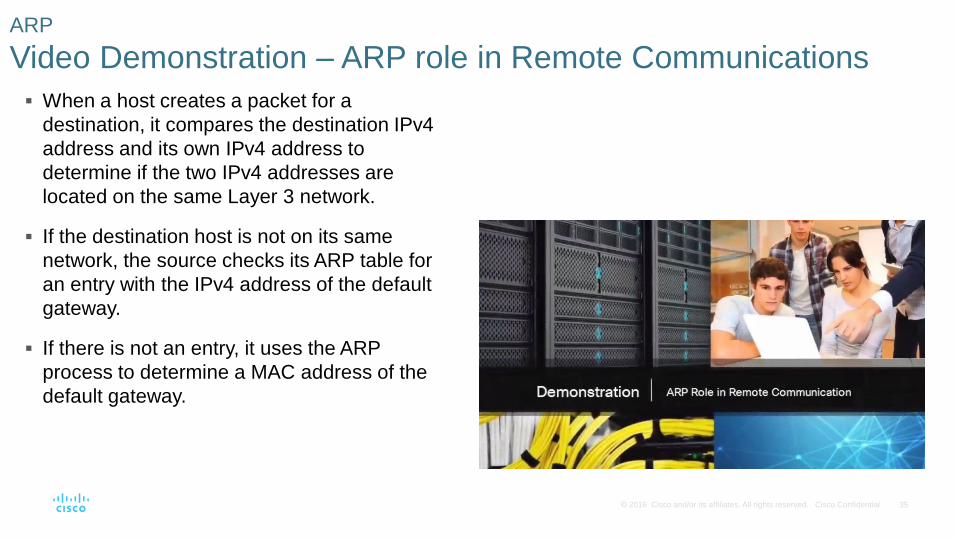
When a host creates a packet for a
destination, it compares the destination IPv4
address and its own IPv4 address to
determine if the two IPv4 addresses are
located on the same Layer 3 network.
If the destination host is not on its same
network, the source checks its ARP table for
an entry with the IPv4 address of the default
gateway.
If there is not an entry, it uses the ARP
process to determine a MAC address of the
default gateway.
ARP
Video Demonstration – ARP role in Remote Communications
36 © 2016 Cisco and/or its affiliates. All rights reserved. Cisco Confidential
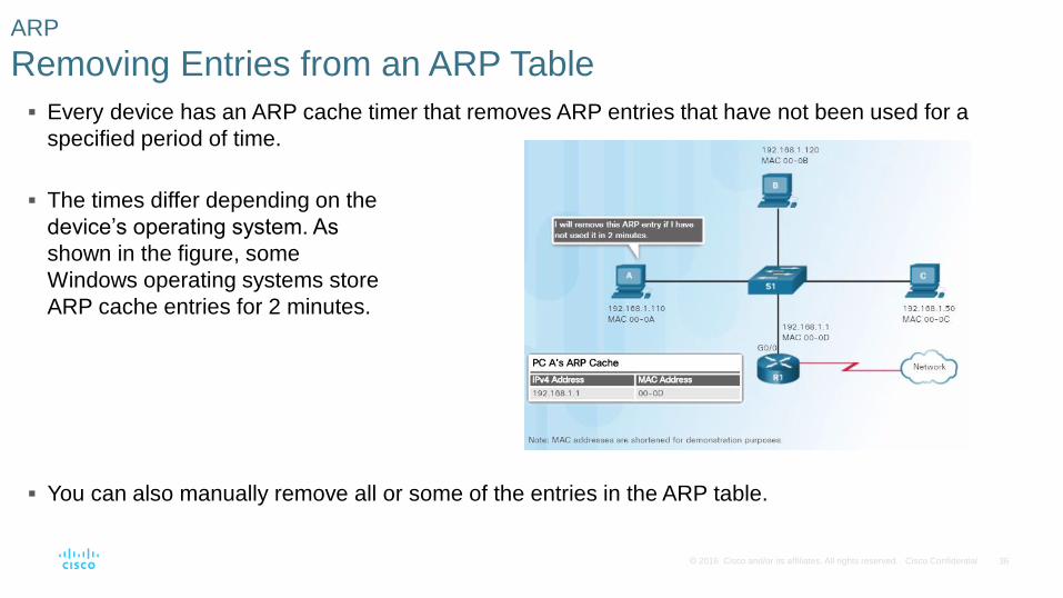
Every device has an ARP cache timer that removes ARP entries that have not been used for a
specified period of time.
You can also manually remove all or some of the entries in the ARP table.
ARP
Removing Entries from an ARP Table
The times differ depending on the
device’s operating system. As
shown in the figure, some
Windows operating systems store
ARP cache entries for 2 minutes.
37 © 2016 Cisco and/or its affiliates. All rights reserved. Cisco Confidential
ARP
ARP Tables
On a Router On a Windows Host
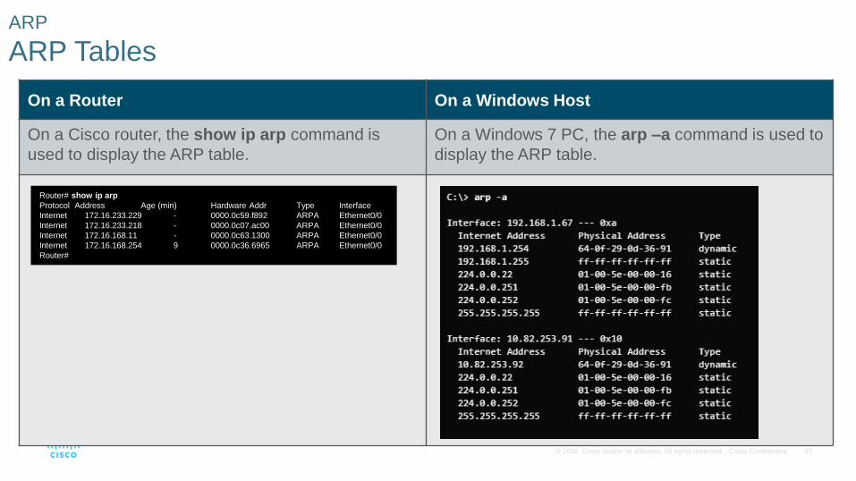
On a Cisco router, the show ip arp command is
used to display the ARP table.
On a Windows 7 PC, the arp –a command is used to
display the ARP table.
Router# show ip arp
Protocol Address Age (min) Hardware Addr Type Interface
Internet 172.16.233.229 - 0000.0c59.f892 ARPA Ethernet0/0
Internet 172.16.233.218 - 0000.0c07.ac00 ARPA Ethernet0/0
Internet 172.16.168.11 - 0000.0c63.1300 ARPA Ethernet0/0
Internet 172.16.168.254 9 0000.0c36.6965 ARPA Ethernet0/0
Router#
38 © 2016 Cisco and/or its affiliates. All rights reserved. Cisco Confidential
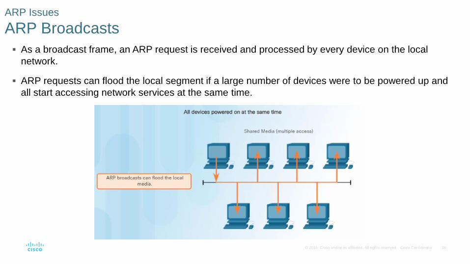
As a broadcast frame, an ARP request is received and processed by every device on the local
network.
ARP requests can flood the local segment if a large number of devices were to be powered up and
all start accessing network services at the same time.
ARP Issues
ARP Broadcasts
39 © 2016 Cisco and/or its affiliates. All rights reserved. Cisco Confidential
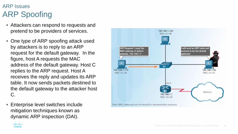
Attackers can respond to requests and
pretend to be providers of services.
One type of ARP spoofing attack used
by attackers is to reply to an ARP
request for the default gateway. In the
figure, host A requests the MAC
address of the default gateway. Host C
replies to the ARP request. Host A
receives the reply and updates its ARP
table. It now sends packets destined to
the default gateway to the attacker host
C.
Enterprise level switches include
mitigation techniques known as
dynamic ARP inspection (DAI).
ARP Issues
ARP Spoofing
40 © 2016 Cisco and/or its affiliates. All rights reserved. Cisco Confidential
5.4 Chapter Summary
41 © 2016 Cisco and/or its affiliates. All rights reserved. Cisco Confidential
Explain the operation of Ethernet.
Explain how a switch operates.
Explain how the address resolution protocol enables communication on a network.
Conclusion
Chapter 5: Ethernet