chapter 4 network layer - student.cs.uwaterloo.cacs456/s08/week4.pdf · typically a tcp or udp...
TRANSCRIPT

1
Chapter 4Network Layer
A note on the use of these ppt slides:We’re making these slides freely available to all (faculty, students, readers). They’re in PowerPoint form so you can add, modify, and delete slides (including this one) and slide content to suit your needs. They obviously represent a lot of work on our part. In return for use, we only ask the following:� If you use these slides (e.g., in a class) in substantially unaltered form, that you mention their source (after all, we’d like people to use our book!)� If you post any slides in substantially unaltered form on a www site, that you note that they are adapted from (or perhaps identical to) our slides, and note our copyright of this material.
Thanks and enjoy! JFK/KWR
All material copyright 1996-2007J.F Kurose and K.W. Ross, All Rights Reserved
Computer Networking: A Top Down Approach 4th edition. Jim Kurose, Keith RossAddison-Wesley, July 2007.

2
Chapter 4: Network Layer
Chapter goals:❒ understand principles behind network layer services:❍ network layer service models
❍ forwarding versus routing
❍ how a router works
❍ routing (path selection)
❍ dealing with scale
❍ advanced topics: IPv6, mobility
❒ instantiation, implementation in the Internet

3
Chapter 4: Network Layer
❒ 4. 1 Introduction
❒ 4.2 Virtual circuit and datagram networks
❒ 4.3 What’s inside a router
❒ 4.4 IP: Internet Protocol❍ Datagram format
❍ IPv4 addressing
❍ ICMP
❍ IPv6
❒ 4.5 Routing algorithms❍ Link state
❍ Distance Vector
❍ Hierarchical routing
❒ 4.6 Routing in the Internet
❍ RIP
❍ OSPF
❍ BGP
❒ 4.7 Broadcast and multicast routing

4
Network layer
❒ transport segment from sending to receiving host
❒ on sending side encapsulates segments into datagrams
❒ on rcving side, delivers segments to transport layer
❒ network layer protocols in every host, router
❒ router examines header fields in all IP datagrams passing through it
applicationtransportnetworkdata linkphysical
applicationtransportnetworkdata linkphysical
networkdata linkphysical network
data linkphysical
networkdata linkphysical
networkdata linkphysical
networkdata linkphysical
networkdata linkphysical
networkdata linkphysical
networkdata linkphysical
networkdata linkphysical
networkdata linkphysicalnetwork
data linkphysical

5
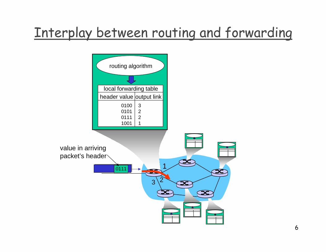
Two Key Network-Layer Functions
❒ forwarding: move packets from router’s input to appropriate router output
❒ routing: determine route taken by packets from source to dest.
❍ routing algorithms
analogy:
❒ routing: process of planning trip from source to dest
❒ forwarding: process of getting through single interchange
6
1
23
0111
value in arrivingpacket’s header
routing algorithm
local forwarding tableheader value output link
0100010101111001
3221
Interplay between routing and forwarding

7
Connection setup
❒ 3rd important function in some network architectures:
❍ATM, frame relay, X.25
❒ before datagrams flow, two end hosts andintervening routers establish virtual connection
❍ routers get involved
8
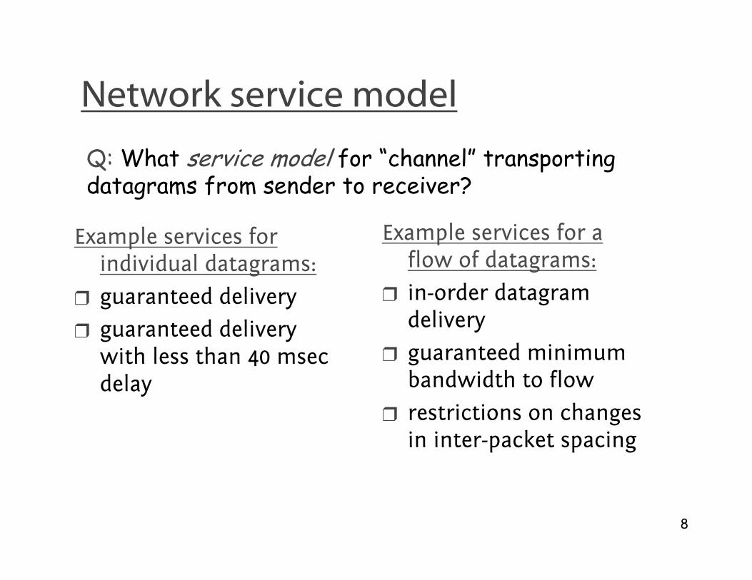
Network service model
Q: What service model for “channel” transporting datagrams from sender to receiver?
Example services for individual datagrams:
❒ guaranteed delivery
❒ guaranteed delivery with less than 40 msec delay
Example services for a flow of datagrams:
❒ in-order datagram delivery
❒ guaranteed minimum bandwidth to flow
❒ restrictions on changes in inter-packet spacing

9
Chapter 4: Network Layer
❒ 4. 1 Introduction
❒ 4.2 Virtual circuit and datagram networks
❒ 4.3 What’s inside a router
❒ 4.4 IP: Internet Protocol❍ Datagram format
❍ IPv4 addressing
❍ ICMP
❍ IPv6
❒ 4.5 Routing algorithms❍ Link state
❍ Distance Vector
❍ Hierarchical routing
❒ 4.6 Routing in the Internet
❍ RIP
❍ OSPF
❍ BGP
❒ 4.7 Broadcast and multicast routing

10
Network layer connection and connection-less service
❒ datagram network provides network-layer connectionless service
❒ VC network provides network-layer connection service
❒ Specifically:
❍ service: host-to-host
❍ no choice: network provides one or the other
❍ implementation: in network core

11
Virtual circuits
❒ call setup, teardown for each call before data can flow
❒ each packet carries VC identifier (not destination host address)
❒ every router on source-dest path maintains “state” for each passing connection
❒ link, router resources (bandwidth, buffers) may be allocated to VC (dedicated resources = predictable service)
“source-to-dest path behaves much like telephone circuit”
❍ performance-wise
❍ network actions along source-to-dest path

12
VC implementation
a VC consists of:
1. path from source to destination
2. VC numbers, one number for each link along path
3. entries in forwarding tables in routers along path
❒ packet belonging to VC carries VC number (rather than dest address)
❒ VC number can be changed on each link.
❍ New VC number comes from forwarding table

13
Forwarding table
12 22 32
12
3
VC number
interfacenumber
Incoming interface Incoming VC # Outgoing interface Outgoing VC #
1 12 3 222 63 1 18 3 7 2 171 97 3 87… … … …
Forwarding table innorthwest router:
Routers maintain connection state information!

14
Virtual circuits: signaling protocols
❒ used to setup, maintain teardown VC
❒ used in ATM, frame-relay, X.25
❒ not used in today’s Internet
applicationtransportnetworkdata linkphysical
applicationtransportnetworkdata linkphysical
1. Initiate call 2. incoming call
3. Accept call4. Call connected5. Data flow begins 6. Receive data
15
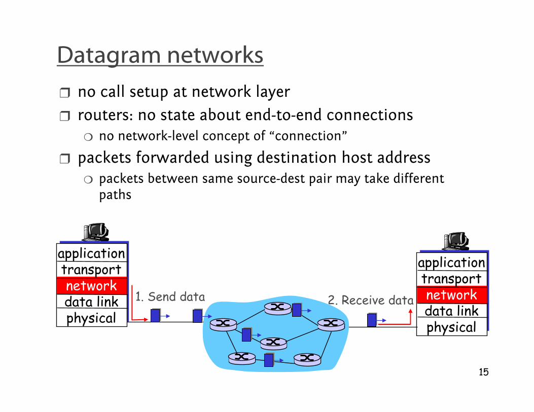
Datagram networks
❒ no call setup at network layer
❒ routers: no state about end-to-end connections❍ no network-level concept of “connection”
❒ packets forwarded using destination host address❍ packets between same source-dest pair may take different
paths
applicationtransportnetworkdata linkphysical
applicationtransportnetworkdata linkphysical
1. Send data 2. Receive data

16
Forwarding table
Destination Address Range Link Interface
11001000 00010111 00010000 00000000through 0
11001000 00010111 00010111 11111111
11001000 00010111 00011000 00000000through 1
11001000 00010111 00011000 11111111
11001000 00010111 00011001 00000000through 2
11001000 00010111 00011111 11111111
otherwise 3
4 billion possible entries

17
Longest prefix matching
Prefix Match Link Interface11001000 00010111 00010 0 11001000 00010111 00011000 111001000 00010111 00011 2
otherwise 3
DA: 11001000 00010111 00011000 10101010
Examples
DA: 11001000 00010111 00010110 10100001 Which interface?
Which interface?
18
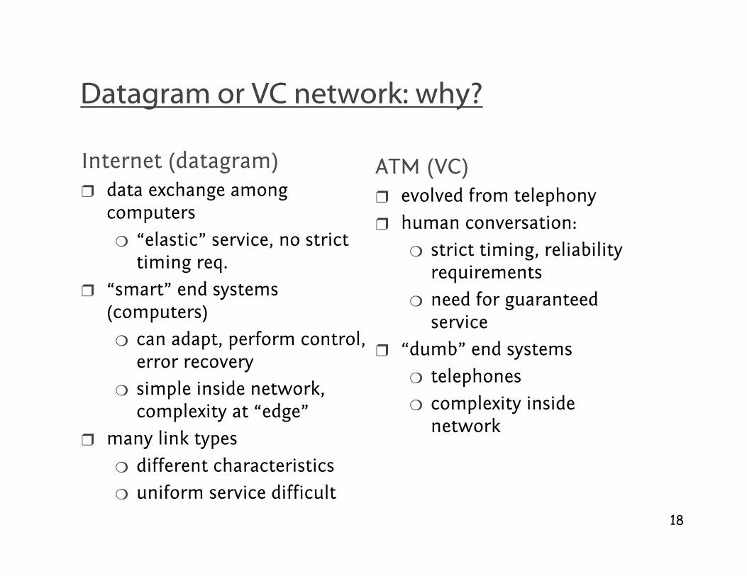
Datagram or VC network: why?
Internet (datagram)❒ data exchange among
computers
❍ “elastic” service, no strict timing req.
❒ “smart” end systems (computers)
❍ can adapt, perform control, error recovery
❍ simple inside network, complexity at “edge”
❒ many link types
❍ different characteristics
❍ uniform service difficult
ATM (VC)❒ evolved from telephony
❒ human conversation:
❍ strict timing, reliability requirements
❍ need for guaranteed service
❒ “dumb” end systems
❍ telephones
❍ complexity inside network

19
Chapter 4: Network Layer
❒ 4. 1 Introduction
❒ 4.2 Virtual circuit and datagram networks
❒ 4.3 What’s inside a router
❒ 4.4 IP: Internet Protocol❍ Datagram format
❍ IPv4 addressing
❍ ICMP
❍ IPv6
❒ 4.5 Routing algorithms❍ Link state
❍ Distance Vector
❍ Hierarchical routing
❒ 4.6 Routing in the Internet
❍ RIP
❍ OSPF
❍ BGP
❒ 4.7 Broadcast and multicast routing
20
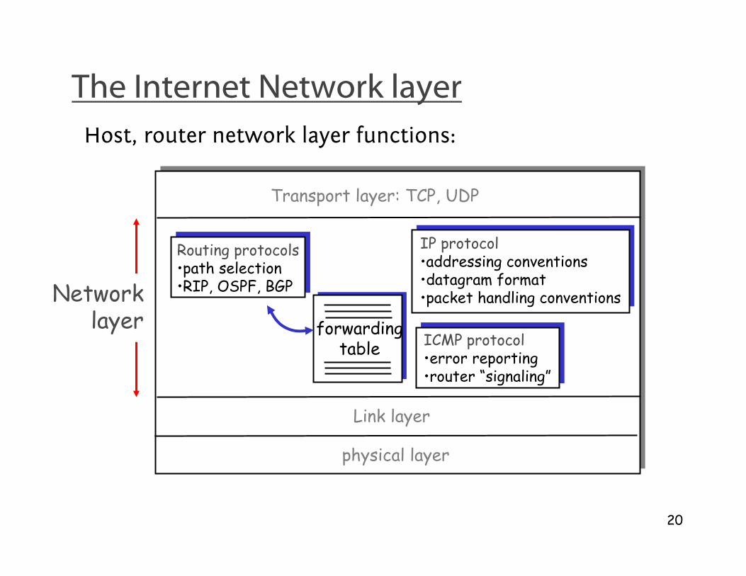
The Internet Network layer
forwardingtable
Host, router network layer functions:
Routing protocols•path selection•RIP, OSPF, BGP
IP protocol•addressing conventions•datagram format•packet handling conventions
ICMP protocol•error reporting•router “signaling”
Transport layer: TCP, UDP
Link layer
physical layer
Networklayer

21
IP datagram format
ver length
32 bits
data (variable length,typically a TCP
or UDP segment)
16-bit identifier
headerchecksum
time tolive
32 bit source IP address
IP protocol versionnumber
header length(bytes)
max numberremaining hops
(decremented at each router)
forfragmentation/reassembly
total datagramlength (bytes)
upper layer protocolto deliver payload to
head.len
type ofservice
“type” of data flgsfragment
offsetupperlayer
32 bit destination IP address
Options (if any) E.g. timestamp,record routetaken, specifylist of routers to visit.
how much overhead with TCP?
❒ 20 bytes of TCP
❒ 20 bytes of IP
❒ = 40 bytes + app layer overhead
22
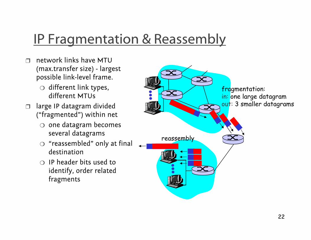
IP Fragmentation & Reassembly
❒ network links have MTU (max.transfer size) - largest possible link-level frame.
❍ different link types, different MTUs
❒ large IP datagram divided (“fragmented”) within net
❍ one datagram becomes several datagrams
❍ “reassembled” only at final destination
❍ IP header bits used to identify, order related fragments
fragmentation: in: one large datagramout: 3 smaller datagrams
reassembly

23
IP Fragmentation and Reassembly
ID=x
offset=0
fragflag=0
length=4000
ID=x
offset=0
fragflag=1
length=1500
ID=x
offset=185
fragflag=1
length=1500
ID=x
offset=370
fragflag=0
length=1040
One large datagram becomesseveral smaller datagrams
Example
❒ 4000 byte datagram
❒ MTU = 1500 bytes
1480 bytes in data field
offset =1480/8

24
Chapter 4: Network Layer
❒ 4. 1 Introduction
❒ 4.2 Virtual circuit and datagram networks
❒ 4.3 What’s inside a router
❒ 4.4 IP: Internet Protocol❍ Datagram format
❍ IPv4 addressing
❍ ICMP
❍ IPv6
❒ 4.5 Routing algorithms❍ Link state
❍ Distance Vector
❍ Hierarchical routing
❒ 4.6 Routing in the Internet
❍ RIP
❍ OSPF
❍ BGP
❒ 4.7 Broadcast and multicast routing
25
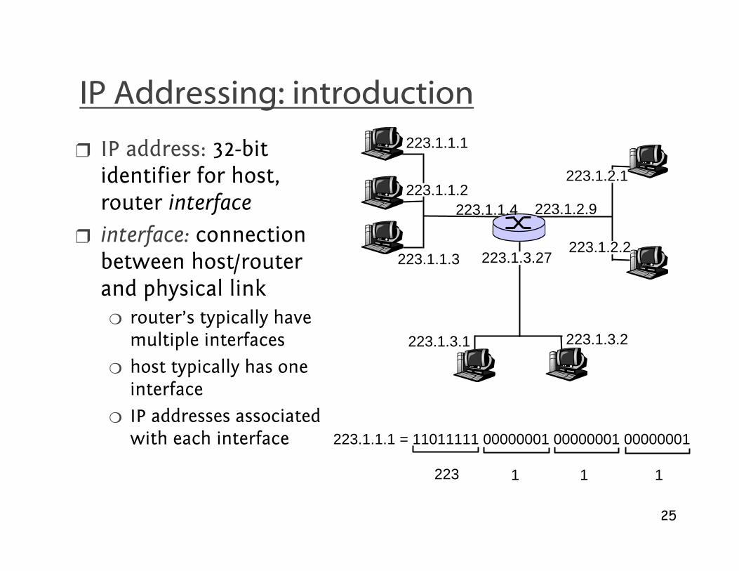
IP Addressing: introduction
❒ IP address: 32-bit identifier for host, router interface
❒ interface: connection between host/router and physical link
❍ router’s typically have multiple interfaces
❍ host typically has one interface
❍ IP addresses associated with each interface
223.1.1.1
223.1.1.2
223.1.1.3
223.1.1.4 223.1.2.9
223.1.2.2
223.1.2.1
223.1.3.2223.1.3.1
223.1.3.27
223.1.1.1 = 11011111 00000001 00000001 00000001
223 1 11
26
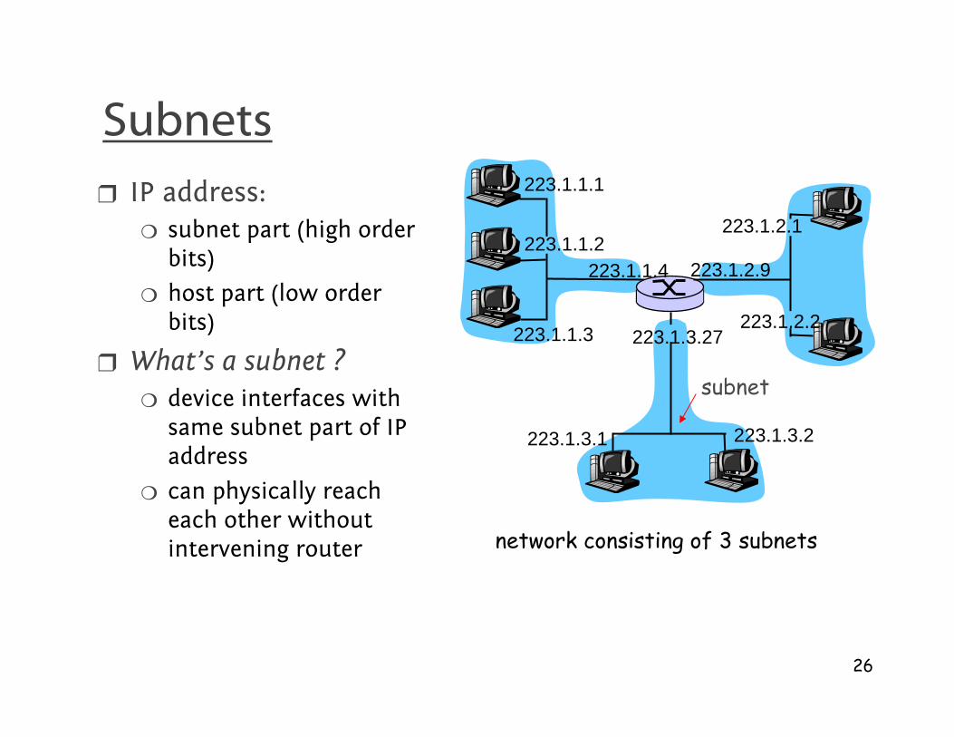
Subnets
❒ IP address:❍ subnet part (high order
bits)
❍ host part (low order bits)
❒ What’s a subnet ?❍ device interfaces with
same subnet part of IP address
❍ can physically reach each other without intervening router
223.1.1.1
223.1.1.2
223.1.1.3
223.1.1.4 223.1.2.9
223.1.2.2
223.1.2.1
223.1.3.2223.1.3.1
223.1.3.27
network consisting of 3 subnets
subnet

27
Subnets 223.1.1.0/24223.1.2.0/24
223.1.3.0/24
Recipe
❒ To determine the subnets, detach each interface from its host or router, creating islands of isolated networks. Each isolated network is called a subnet.
Subnet mask: /24

28
Subnets
How many? 223.1.1.1
223.1.1.3
223.1.1.4
223.1.2.2223.1.2.1
223.1.2.6
223.1.3.2223.1.3.1
223.1.3.27
223.1.1.2
223.1.7.0
223.1.7.1223.1.8.0223.1.8.1
223.1.9.1
223.1.9.2

29
IP addressing: CIDR
CIDR: Classless InterDomain Routing❍ subnet portion of address of arbitrary length
❍ address format: a.b.c.d/x, where x is # bits in subnet portion of address
11001000 00010111 00010000 00000000
subnetpart
hostpart
200.23.16.0/23

30
IP addresses: how to get one?
Q: How does host get IP address?
❒ hard-coded by system admin in a file
❍ Wintel: control-panel->network->configuration->tcp/ip->properties
❍ UNIX: /etc/rc.config
❒ DHCP: Dynamic Host Configuration Protocol: dynamically get address from as server
❍ “plug-and-play”

31
IP addresses: how to get one?
Q: How does network get subnet part of IP addr?
A: gets allocated portion of its provider ISP’s address space
ISP's block 11001000 00010111 00010000 00000000 200.23.16.0/20
Organization 0 11001000 00010111 00010000 00000000 200.23.16.0/23 Organization 1 11001000 00010111 00010010 00000000 200.23.18.0/23 Organization 2 11001000 00010111 00010100 00000000 200.23.20.0/23
... ….. …. ….
Organization 7 11001000 00010111 00011110 00000000 200.23.30.0/23

32
Hierarchical addressing: route aggregation
“Send me anythingwith addresses beginning 200.23.16.0/20”
200.23.16.0/23
200.23.18.0/23
200.23.30.0/23
Fly-By-Night-ISP
Organization 0
Organization 7Internet
Organization 1
ISPs-R-Us“Send me anythingwith addresses beginning 199.31.0.0/16”
200.23.20.0/23Organization 2
.
.
.
.
.
.
Hierarchical addressing allows efficient advertisement of routing information:

33
Hierarchical addressing: more specific routes
ISPs-R-Us has a more specific route to Organization 1
“Send me anythingwith addresses beginning 200.23.16.0/20”
200.23.16.0/23
200.23.18.0/23
200.23.30.0/23
Fly-By-Night-ISP
Organization 0
Organization 7Internet
Organization 1
ISPs-R-Us“Send me anythingwith addresses beginning 199.31.0.0/16or 200.23.18.0/23”
200.23.20.0/23Organization 2
.
.
.
.
.
.

34
IP addressing: the last word...
Q: How does an ISP get block of addresses?
A: ICANN: Internet Corporation for Assigned
Names and Numbers
❍ allocates addresses
❍ manages DNS
❍ assigns domain names, resolves disputes

35
Chapter 5: Link Layer
❒ 5.1 Introduction and services
❒ 5.2 Error detection and correction
❒ 5.3Multiple access protocols
❒ 5.4 Link-Layer Addressing (ARP)
❒ 5.5 Ethernet
❒ 5.6 Link-layer switches
❒ 5.7 PPP
❒ 5.8 Link Virtualization: ATM, MPLS

36
ARP: Address Resolution Protocol
❒ Each IP node (host, router) on LAN has ARP table
❒ ARP table: IP/MAC address mappings for some LAN nodes< IP address; MAC address; TTL>
❍ TTL (Time To Live): time after which address mapping will be forgotten (typically 20 min)
Question: how to determineMAC address of Bknowing B’s IP address?
1A-2F-BB-76-09-AD
58-23-D7-FA-20-B0
0C-C4-11-6F-E3-98
71-65-F7-2B-08-53
LAN
137.196.7.23
137.196.7.78
137.196.7.14
137.196.7.88

37
ARP protocol: Same LAN (network)
❒ A wants to send datagram to B, and B’s MAC address not in A’s ARP table.
❒ A broadcasts ARP query packet, containing B's IP address
❍ dest MAC address = FF-FF-FF-FF-FF-FF
❍ all machines on LAN receive ARP query
❒ B receives ARP packet, replies to A with its (B's) MAC address
❍ frame sent to A’s MAC address (unicast)
❒ A caches (saves) IP-to-MAC address pair in its ARP table until information becomes old (times out)
❍ soft state: information that times out (goes away) unless refreshed
❒ ARP is “plug-and-play”:❍ nodes create their ARP
tables without intervention from net administrator
38
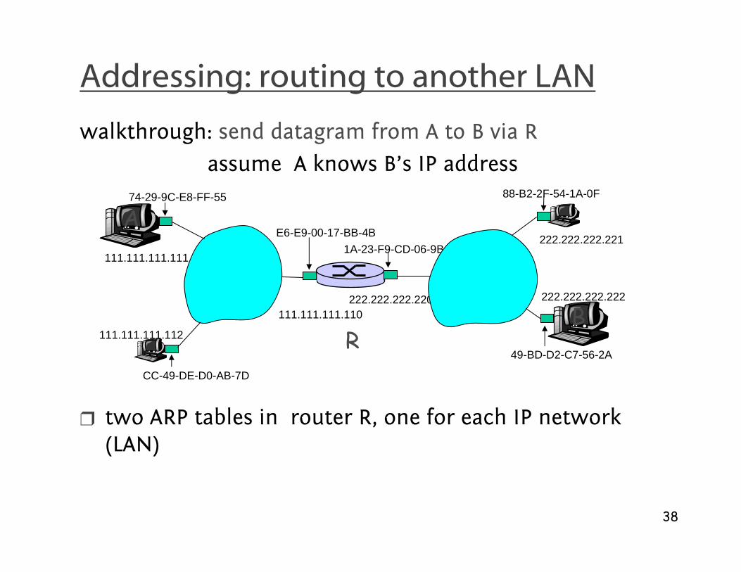
Addressing: routing to another LAN
R
1A-23-F9-CD-06-9B
222.222.222.220111.111.111.110
E6-E9-00-17-BB-4B
CC-49-DE-D0-AB-7D
111.111.111.112
111.111.111.111
A74-29-9C-E8-FF-55
222.222.222.221
88-B2-2F-54-1A-0F
B222.222.222.222
49-BD-D2-C7-56-2A
walkthrough: send datagram from A to B via R
assume A knows B’s IP address
❒ two ARP tables in router R, one for each IP network (LAN)

39
❒ A creates IP datagram with source A, destination B
❒ A uses ARP to get R’s MAC address for 111.111.111.110
❒ A creates link-layer frame with R's MAC address as dest, frame contains A-to-B IP datagram
❒ A’s NIC sends frame
❒ R’s NIC receives frame
❒ R removes IP datagram from Ethernet frame, sees its destined to B
❒ R uses ARP to get B’s MAC address
❒ R creates frame containing A-to-B IP datagram sends to B
R
1A-23-F9-CD-06-9B
222.222.222.220
111.111.111.110
E6-E9-00-17-BB-4B
CC-49-DE-D0-AB-7D
111.111.111.112
111.111.111.111
A74-29-9C-E8-FF-55
222.222.222.221
88-B2-2F-54-1A-0F
B222.222.222.222
49-BD-D2-C7-56-2A
This is a really importantexample – make sure youunderstand!

40
Chapter 4: Network Layer
❒ 4. 1 Introduction
❒ 4.2 Virtual circuit and datagram networks
❒ 4.3 What’s inside a router
❒ 4.4 IP: Internet Protocol❍ Datagram format
❍ IPv4 addressing (DHCP)
❍ ICMP
❍ IPv6
❒ 4.5 Routing algorithms❍ Link state
❍ Distance Vector
❍ Hierarchical routing
❒ 4.6 Routing in the Internet
❍ RIP
❍ OSPF
❍ BGP
❒ 4.7 Broadcast and multicast routing

41
DHCP: Dynamic Host Configuration Protocol
Goal: allow host to dynamically obtain its IP address from network server when joining network
❍ support for mobile users joining network
❍ host holds address only while connected and “on”(allowing address reuse)
❍ renew address already in use
❒ DHCP overview:
❍ 1. host broadcasts “DHCP discover” msg
❍ 2. DHCP server responds with “DHCP offer” msg
❍ 3. host requests IP address: “DHCP request” msg
❍ 4. DHCP server sends address: “DHCP ack” msg

42
DHCP client-server scenario
223.1.1.1
223.1.1.2
223.1.1.3
223.1.1.4 223.1.2.9
223.1.2.2
223.1.2.1
223.1.3.2223.1.3.1
223.1.3.27
A
B
E
DHCP server
arriving DHCP client needsaddress in this(223.1.2/24) network

43
DHCP client-server scenario
DHCP server: 223.1.2.5 arrivingclient
time
DHCP discover
src : 0.0.0.0, 68 dest.: 255.255.255.255,67yiaddr: 0.0.0.0transaction ID: 654
DHCP offer
src: 223.1.2.5, 67 dest: 255.255.255.255, 68yiaddrr: 223.1.2.4transaction ID: 654Lifetime: 3600 secs
DHCP request
src: 0.0.0.0, 68 dest:: 255.255.255.255, 67yiaddrr: 223.1.2.4transaction ID: 655Lifetime: 3600 secs
DHCP ACK
src: 223.1.2.5, 67 dest: 255.255.255.255, 68yiaddrr: 223.1.2.4transaction ID: 655Lifetime: 3600 secs

44
Chapter 4: Network Layer
❒ 4. 1 Introduction
❒ 4.2 Virtual circuit and datagram networks
❒ 4.3 What’s inside a router
❒ 4.4 IP: Internet Protocol❍ Datagram format
❍ IPv4 addressing
❍ ICMP
❍ IPv6
❒ 4.5 Routing algorithms❍ Link state
❍ Distance Vector
❍ Hierarchical routing
❒ 4.6 Routing in the Internet
❍ RIP
❍ OSPF
❍ BGP
❒ 4.7 Broadcast and multicast routing

45
ICMP: Internet Control Message Protocol
❒ used by hosts & routers to communicate network-level information
❍ error reporting: unreachable host, network, port, protocol
❍ echo request/reply (used by ping)
❒ network-layer “above” IP:
❍ ICMP msgs carried in IP datagrams
❒ ICMP message: type, code plus first 8 bytes of IP datagram causing error
Type Code description0 0 echo reply (ping)3 0 dest. network unreachable3 1 dest host unreachable3 2 dest protocol unreachable3 3 dest port unreachable3 6 dest network unknown3 7 dest host unknown4 0 source quench (congestion
control - not used)8 0 echo request (ping)9 0 route advertisement10 0 router discovery11 0 TTL expired12 0 bad IP header

46
Traceroute and ICMP
❒ Source sends series of UDP segments to dest
❍ First has TTL =1
❍ Second has TTL=2, etc.
❍ Unlikely port number
❒ When nth datagram arrives to nth router:
❍ Router discards datagram
❍ And sends to source an ICMP message (type 11, code 0)
❍ Message includes name of router& IP address
❒ When ICMP message arrives, source calculates RTT
❒ Traceroute does this 3 times
Stopping criterion
❒ UDP segment eventually arrives at destination host
❒ Destination returns ICMP “port unreachable” packet (type 3, code 3)
❒ When source gets this ICMP, stops.

47
Chapter 4: Network Layer
❒ 4. 1 Introduction
❒ 4.2 Virtual circuit and datagram networks
❒ 4.3 What’s inside a router
❒ 4.4 IP: Internet Protocol❍ Datagram format
❍ IPv4 addressing
❍ ICMP
❍ IPv6
❒ 4.5 Routing algorithms❍ Link state
❍ Distance Vector
❍ Hierarchical routing
❒ 4.6 Routing in the Internet
❍ RIP
❍ OSPF
❍ BGP
❒ 4.7 Broadcast and multicast routing

48
IPv6
❒ Initial motivation: 32-bit address space soon to be completely allocated.
❒ Additional motivation:
❍ header format helps speed processing/forwarding
❍ header changes to facilitate QoS
IPv6 datagram format:
❍ fixed-length 40 byte header
❍ no fragmentation allowed
49
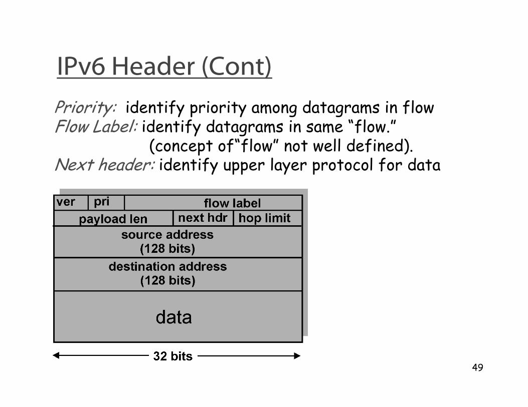
IPv6 Header (Cont)
Priority: identify priority among datagrams in flowFlow Label: identify datagrams in same “flow.”
(concept of“flow” not well defined).Next header: identify upper layer protocol for data
50
Other Changes from IPv4
❒ Checksum: removed entirely to reduce processing time at each hop
❒ Options: allowed, but outside of header, indicated by “Next Header” field
❒ ICMPv6: new version of ICMP
❍ additional message types, e.g. “Packet Too Big”
❍ multicast group management functions

51
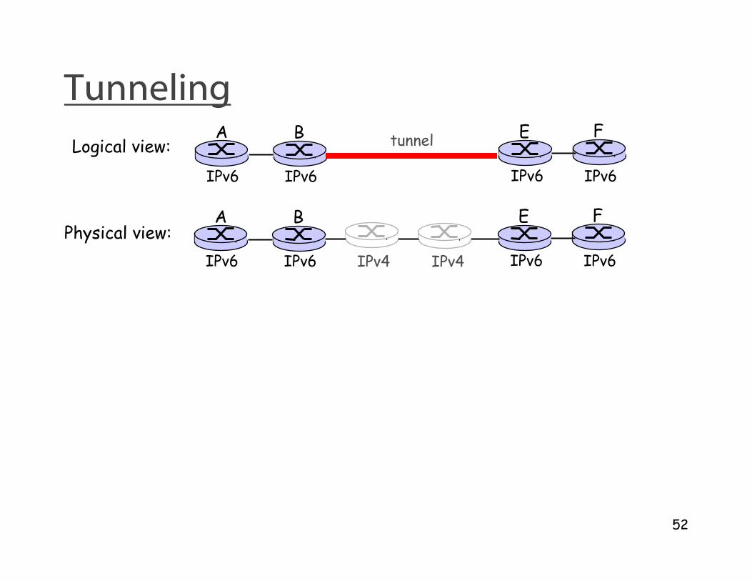
Transition From IPv4 To IPv6
❒ Not all routers can be upgraded simultaneous
❍ no “flag days”
❍ How will the network operate with mixed IPv4 and IPv6 routers?
❒ Tunneling: IPv6 carried as payload in IPv4 datagram among IPv4 routers
52
TunnelingA B E F
IPv6 IPv6 IPv6 IPv6
tunnelLogical view:
Physical view:A B E F
IPv6 IPv6 IPv6 IPv6IPv4 IPv4
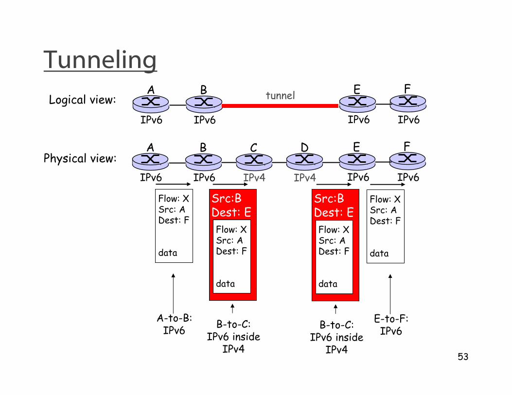
53
TunnelingA B E F
IPv6 IPv6 IPv6 IPv6
tunnelLogical view:
Physical view:A B E F
IPv6 IPv6 IPv6 IPv6
C D
IPv4 IPv4
Flow: XSrc: ADest: F
data
Flow: XSrc: ADest: F
data
Flow: XSrc: ADest: F
data
Src:BDest: E
Flow: XSrc: ADest: F
data
Src:BDest: E
A-to-B:IPv6
E-to-F:IPv6
B-to-C:IPv6 inside
IPv4
B-to-C:IPv6 inside
IPv4

54
Gateway
❒ Interaction between IPv6 clients and IPv4 servers – or vice versa?
❍ tunneling does not help
❒ Solution: special “IPv4” address range in IPv6
addresses
❒ Need protocol gateway to convert between
IPv4 and IPv6
❒ More complicated than tunneling