chapter 3 structure - university of tennesseeprack/mse201/chapter 3 structure.pdf · introduction...
TRANSCRIPT
1
Introduction To Materials Science, Chapter 3, The structure of crystalline solids
University of Tennessee, Dept. of Materials Science and Engineering 1
How do atoms arrange themselves to form solids?
• Fundamental concepts and language• Unit cells• Crystal structures
Simple cubic Face-centered cubicBody-centered cubicHexagonal close-packed
• Close packed crystal structures• Density computations• Types of solids
Single crystalPolycrystallineAmorphous
Chapter Outline
Introduction To Materials Science, Chapter 3, The structure of crystalline solids
University of Tennessee, Dept. of Materials Science and Engineering 2
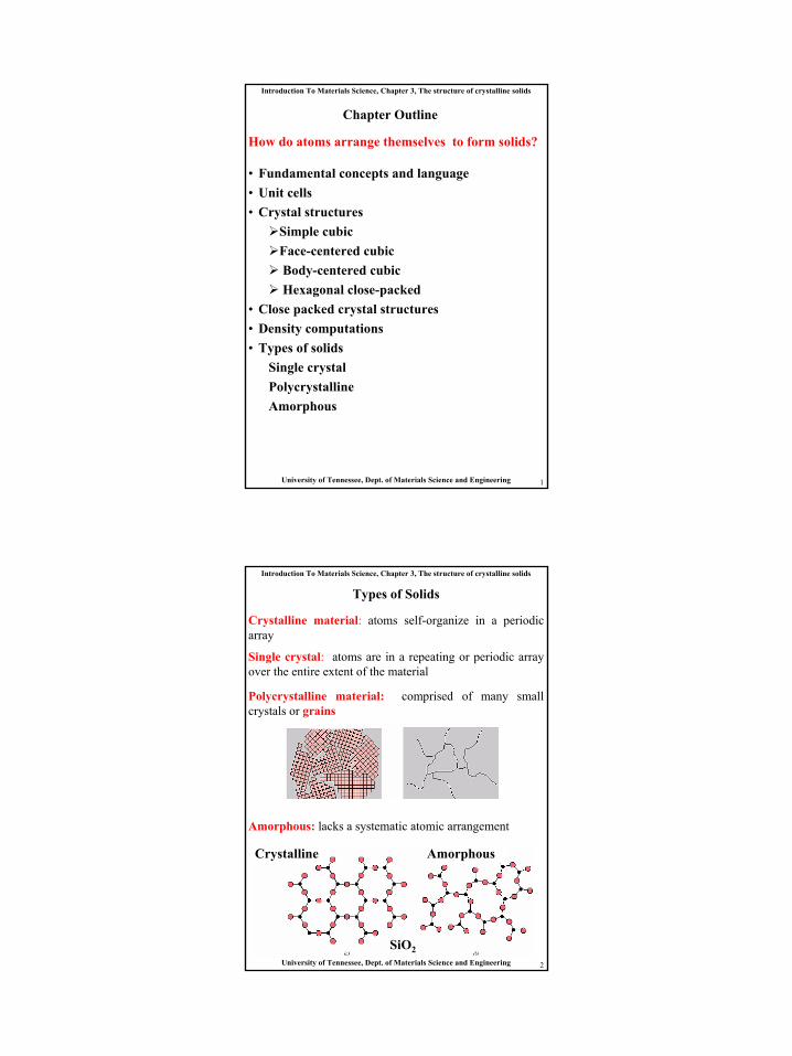
Types of Solids
Crystalline material: atoms self-organize in a periodic array
Single crystal: atoms are in a repeating or periodic array over the entire extent of the material
Polycrystalline material: comprised of many small crystals or grains
Amorphous: lacks a systematic atomic arrangement
Crystalline Amorphous
SiO2
2
Introduction To Materials Science, Chapter 3, The structure of crystalline solids
University of Tennessee, Dept. of Materials Science and Engineering 3
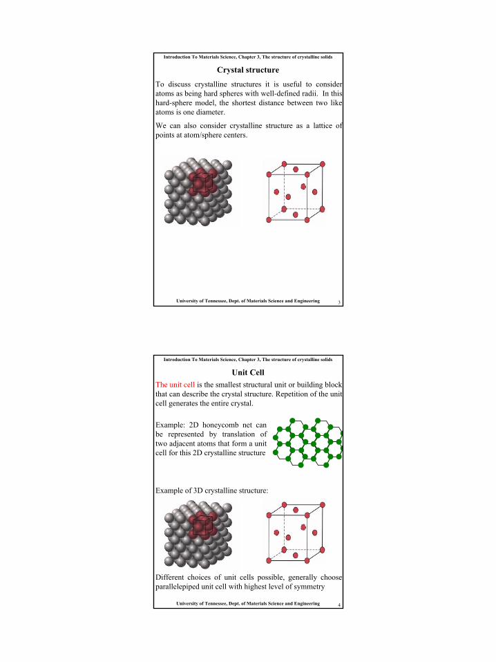
Crystal structure
To discuss crystalline structures it is useful to consider atoms as being hard spheres with well-defined radii. In this hard-sphere model, the shortest distance between two like atoms is one diameter.
We can also consider crystalline structure as a lattice of points at atom/sphere centers.
Introduction To Materials Science, Chapter 3, The structure of crystalline solids
University of Tennessee, Dept. of Materials Science and Engineering 4
Unit CellThe unit cell is the smallest structural unit or building block that can describe the crystal structure. Repetition of the unit cell generates the entire crystal.
Different choices of unit cells possible, generally choose parallelepiped unit cell with highest level of symmetry
Example: 2D honeycomb net can be represented by translation of two adjacent atoms that form a unit cell for this 2D crystalline structure
Example of 3D crystalline structure:
3
Introduction To Materials Science, Chapter 3, The structure of crystalline solids
University of Tennessee, Dept. of Materials Science and Engineering 5
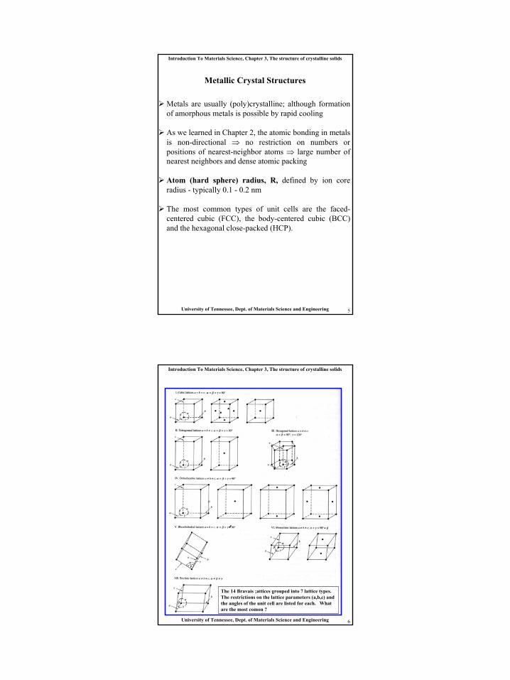
Metallic Crystal Structures
Metals are usually (poly)crystalline; although formation of amorphous metals is possible by rapid cooling
As we learned in Chapter 2, the atomic bonding in metals is non-directional ⇒ no restriction on numbers or positions of nearest-neighbor atoms ⇒ large number of nearest neighbors and dense atomic packing
Atom (hard sphere) radius, R, defined by ion core radius - typically 0.1 - 0.2 nm
The most common types of unit cells are the faced-centered cubic (FCC), the body-centered cubic (BCC) and the hexagonal close-packed (HCP).
Introduction To Materials Science, Chapter 3, The structure of crystalline solids
University of Tennessee, Dept. of Materials Science and Engineering 6
The 14 Bravais ;attices grouped into 7 lattice types.The restrictions on the lattice parameters (a,b,c) and the angles of the unit cell are listed for each. Whatare the most comon ?
4
Introduction To Materials Science, Chapter 3, The structure of crystalline solids
University of Tennessee, Dept. of Materials Science and Engineering 7
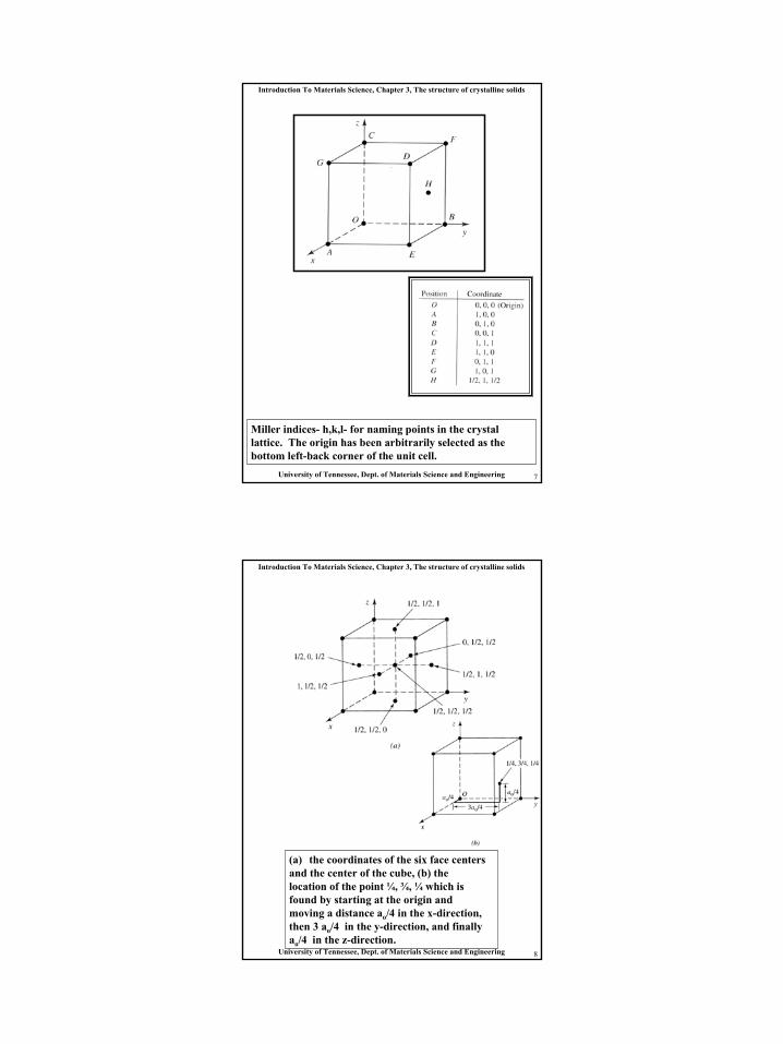
Miller indices- h,k,l- for naming points in the crystal lattice. The origin has been arbitrarily selected as the bottom left-back corner of the unit cell.
Introduction To Materials Science, Chapter 3, The structure of crystalline solids
University of Tennessee, Dept. of Materials Science and Engineering 8
(a) the coordinates of the six face centersand the center of the cube, (b) the location of the point ¼, ¾, ¼ which isfound by starting at the origin and moving a distance ao/4 in the x-direction,then 3 ao/4 in the y-direction, and finallyao/4 in the z-direction.
5
Introduction To Materials Science, Chapter 3, The structure of crystalline solids
University of Tennessee, Dept. of Materials Science and Engineering 9
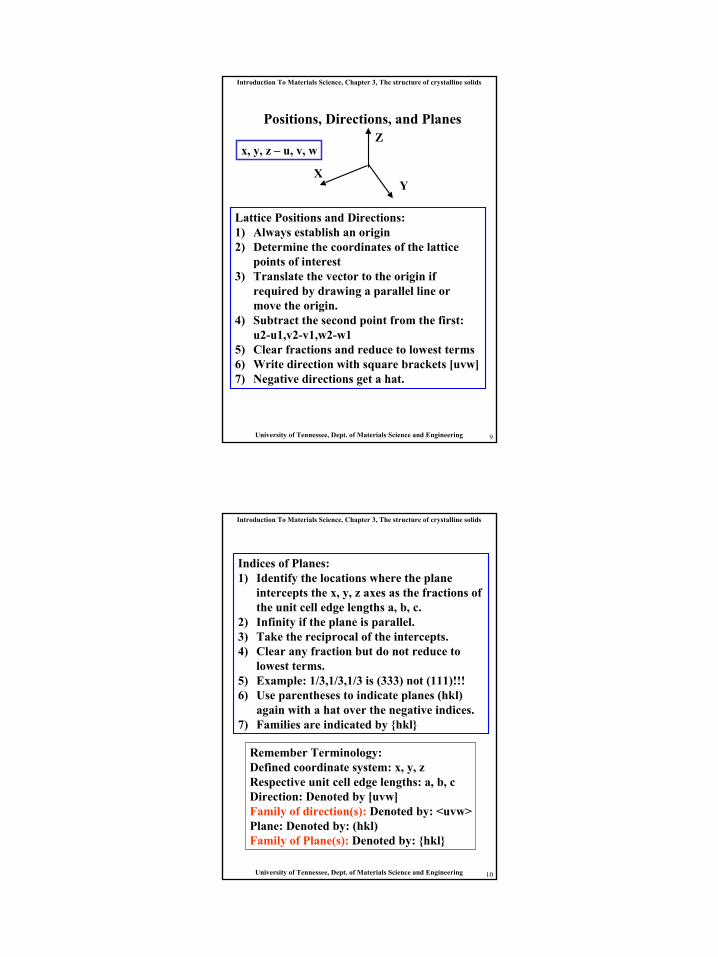
Positions, Directions, and Planes
x, y, z – u, v, w
XY
Z
Lattice Positions and Directions:1) Always establish an origin2) Determine the coordinates of the lattice
points of interest3) Translate the vector to the origin if
required by drawing a parallel line or move the origin.
4) Subtract the second point from the first: u2-u1,v2-v1,w2-w1
5) Clear fractions and reduce to lowest terms6) Write direction with square brackets [uvw]7) Negative directions get a hat.
Introduction To Materials Science, Chapter 3, The structure of crystalline solids
University of Tennessee, Dept. of Materials Science and Engineering 10
Indices of Planes:1) Identify the locations where the plane
intercepts the x, y, z axes as the fractions of the unit cell edge lengths a, b, c.
2) Infinity if the plane is parallel.3) Take the reciprocal of the intercepts. 4) Clear any fraction but do not reduce to
lowest terms. 5) Example: 1/3,1/3,1/3 is (333) not (111)!!!6) Use parentheses to indicate planes (hkl)
again with a hat over the negative indices.7) Families are indicated by {hkl}
Remember Terminology:Defined coordinate system: x, y, zRespective unit cell edge lengths: a, b, c Direction: Denoted by [uvw]Family of direction(s): Denoted by: <uvw>Plane: Denoted by: (hkl)Family of Plane(s): Denoted by: {hkl}
6
Introduction To Materials Science, Chapter 3, The structure of crystalline solids
University of Tennessee, Dept. of Materials Science and Engineering 11
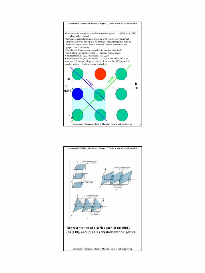
•Directions are always perp. to their respective planes, i.e. [111] perp. (111) (for cubic systems)
•Families of equivalent planes are equal with respect to symmetrical structures, they do not have to be parallel. Equivalent planes must be translated to the correct atomic positions in order to maintain the proper crystal symmetry.
• Families of directions are equivalent in absolute magnitude.• (222) planes are parallel to the (111) planes but not equal.• Intercepts for the (222) planes are 1/2,1/2,1/2• Intercepts for the (333) planes are 1/3,1/3,1/3, remember this is inwhat we call “reciprocal space”. If you draw out the (333) plane it isparallel to the (111) plane but not equivalent.
a
b(110)
0,0,0-b
-a (-110)
Introduction To Materials Science, Chapter 3, The structure of crystalline solids
University of Tennessee, Dept. of Materials Science and Engineering 12
Representation of a series each of (a) (001), (b) (110), and (c) (111) crystallographic planes.
7
Introduction To Materials Science, Chapter 3, The structure of crystalline solids
University of Tennessee, Dept. of Materials Science and Engineering 13
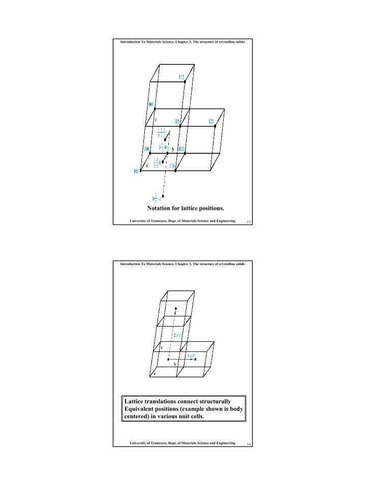
Notation for lattice positions.
Introduction To Materials Science, Chapter 3, The structure of crystalline solids
University of Tennessee, Dept. of Materials Science and Engineering 14
Lattice translations connect structurally Equivalent positions (example shown is bodycentered) in various unit cells.
8
Introduction To Materials Science, Chapter 3, The structure of crystalline solids
University of Tennessee, Dept. of Materials Science and Engineering 15
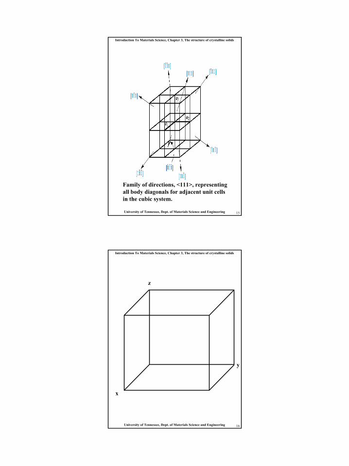
Family of directions, <111>, representing all body diagonals for adjacent unit cellsin the cubic system.
Introduction To Materials Science, Chapter 3, The structure of crystalline solids
University of Tennessee, Dept. of Materials Science and Engineering 16
x
y
z
9
Introduction To Materials Science, Chapter 3, The structure of crystalline solids
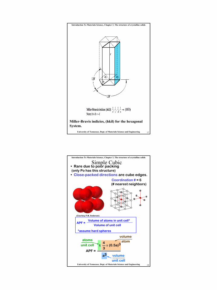
University of Tennessee, Dept. of Materials Science and Engineering 17
Miller-Bravis indicies, (hkil) for the hexagonalSystem.
Introduction To Materials Science, Chapter 3, The structure of crystalline solids
University of Tennessee, Dept. of Materials Science and Engineering 18
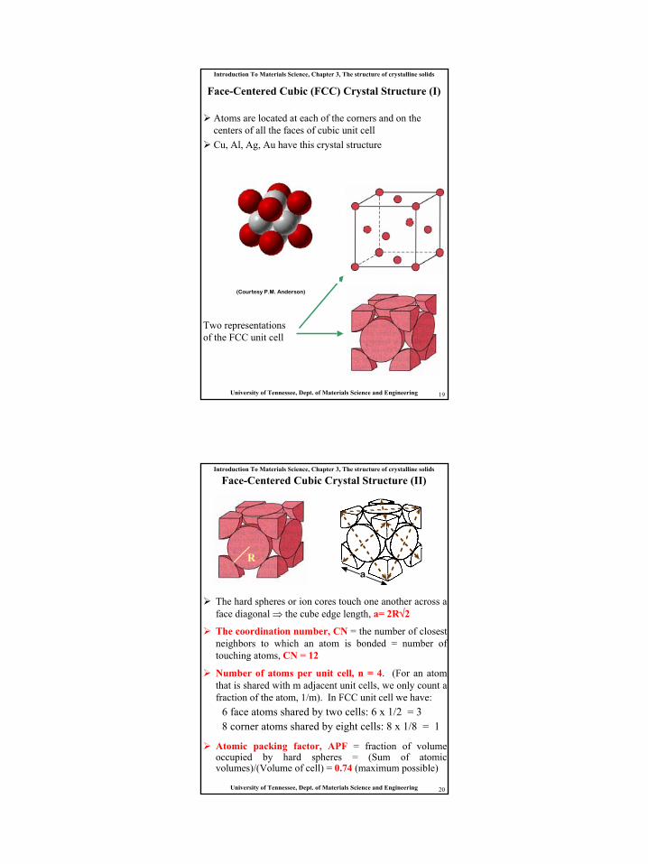
Simple Cubic• Rare due to poor packing(only Po has this structure)• Close-packed directions are cube edges.
• Coordination # = 6(# nearest neighbors)
(Courtesy P.M. Anderson)
APF = Volume of atoms in unit cell*
Volume of unit cell
*assume hard spheres
APF = a3
4
3π (0.5a)31
atoms
unit cellatom
volume
unit cellvolume
10
Introduction To Materials Science, Chapter 3, The structure of crystalline solids
University of Tennessee, Dept. of Materials Science and Engineering 19
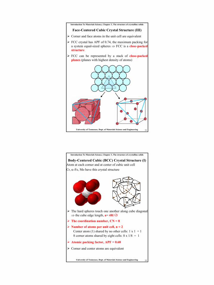
Face-Centered Cubic (FCC) Crystal Structure (I)
Atoms are located at each of the corners and on the centers of all the faces of cubic unit cellCu, Al, Ag, Au have this crystal structure
Two representations of the FCC unit cell
(Courtesy P.M. Anderson)
Introduction To Materials Science, Chapter 3, The structure of crystalline solids
University of Tennessee, Dept. of Materials Science and Engineering 20
The hard spheres or ion cores touch one another across a face diagonal ⇒ the cube edge length, a= 2R√2
The coordination number, CN = the number of closest neighbors to which an atom is bonded = number of touching atoms, CN = 12
Number of atoms per unit cell, n = 4. (For an atom that is shared with m adjacent unit cells, we only count a fraction of the atom, 1/m). In FCC unit cell we have:
6 face atoms shared by two cells: 6 x 1/2 = 38 corner atoms shared by eight cells: 8 x 1/8 = 1
Atomic packing factor, APF = fraction of volume occupied by hard spheres = (Sum of atomic volumes)/(Volume of cell) = 0.74 (maximum possible)
Face-Centered Cubic Crystal Structure (II)
Ra
11
Introduction To Materials Science, Chapter 3, The structure of crystalline solids
University of Tennessee, Dept. of Materials Science and Engineering 21
Corner and face atoms in the unit cell are equivalent
FCC crystal has APF of 0.74, the maximum packing for a system equal-sized spheres ⇒ FCC is a close-packed structure
FCC can be represented by a stack of close-packed planes (planes with highest density of atoms)
Face-Centered Cubic Crystal Structure (III)
Introduction To Materials Science, Chapter 3, The structure of crystalline solids
University of Tennessee, Dept. of Materials Science and Engineering 22
Body-Centered Cubic (BCC) Crystal Structure (I)Atom at each corner and at center of cubic unit cellCr, α-Fe, Mo have this crystal structure
aR
The hard spheres touch one another along cube diagonal ⇒ the cube edge length, a= 4R/√3
The coordination number, CN = 8
Number of atoms per unit cell, n = 2Center atom (1) shared by no other cells: 1 x 1 = 18 corner atoms shared by eight cells: 8 x 1/8 = 1
Atomic packing factor, APF = 0.68
Corner and center atoms are equivalent
12
Introduction To Materials Science, Chapter 3, The structure of crystalline solids
University of Tennessee, Dept. of Materials Science and Engineering 23
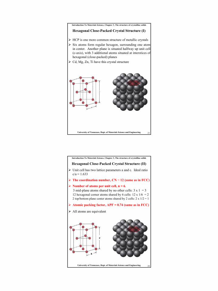
Hexagonal Close-Packed Crystal Structure (I)
HCP is one more common structure of metallic crystals Six atoms form regular hexagon, surrounding one atom in center. Another plane is situated halfway up unit cell (c-axis), with 3 additional atoms situated at interstices of hexagonal (close-packed) planesCd, Mg, Zn, Ti have this crystal structure
Introduction To Materials Science, Chapter 3, The structure of crystalline solids
University of Tennessee, Dept. of Materials Science and Engineering 24
Unit cell has two lattice parameters a and c. Ideal ratio c/a = 1.633
The coordination number, CN = 12 (same as in FCC)
Number of atoms per unit cell, n = 6. 3 mid-plane atoms shared by no other cells: 3 x 1 = 312 hexagonal corner atoms shared by 6 cells: 12 x 1/6 = 22 top/bottom plane center atoms shared by 2 cells: 2 x 1/2 = 1
Atomic packing factor, APF = 0.74 (same as in FCC)
All atoms are equivalent
Hexagonal Close-Packed Crystal Structure (II)
a
c
13
Introduction To Materials Science, Chapter 3, The structure of crystalline solids
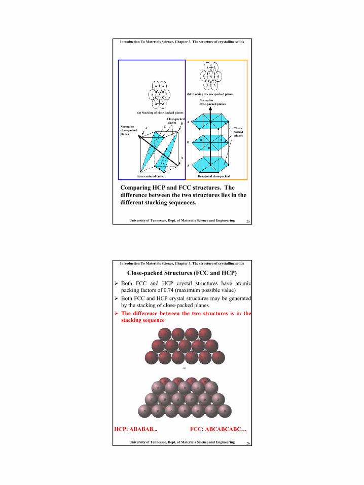
University of Tennessee, Dept. of Materials Science and Engineering 25
Comparing HCP and FCC structures. The difference between the two structures lies in the different stacking sequences.
Close-packedplanes
(a) Stacking of close packed planes
BA C
(b) Stacking of close-packed planes
Normal toclose-packedplanes
Close-packedplanes
Normal to close-packed planes
A
A
A
B
Hexagonal close-packedFace centered cubic
Introduction To Materials Science, Chapter 3, The structure of crystalline solids
University of Tennessee, Dept. of Materials Science and Engineering 26
Both FCC and HCP crystal structures have atomic packing factors of 0.74 (maximum possible value)Both FCC and HCP crystal structures may be generated by the stacking of close-packed planesThe difference between the two structures is in the stacking sequence
Close-packed Structures (FCC and HCP)
HCP: ABABAB... FCC: ABCABCABC…
14
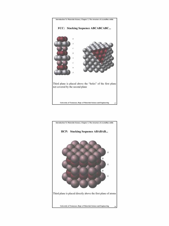
Introduction To Materials Science, Chapter 3, The structure of crystalline solids
University of Tennessee, Dept. of Materials Science and Engineering 27
FCC: Stacking Sequence ABCABCABC...
Third plane is placed above the “holes” of the first plane not covered by the second plane
Introduction To Materials Science, Chapter 3, The structure of crystalline solids
University of Tennessee, Dept. of Materials Science and Engineering 28
HCP: Stacking Sequence ABABAB...
Third plane is placed directly above the first plane of atoms
15
Introduction To Materials Science, Chapter 3, The structure of crystalline solids
University of Tennessee, Dept. of Materials Science and Engineering 29
Density and Atom Packing
• Bulk Measurements– Counting atoms within a unit
cell• Area density in plane
– # atoms/nm2
• Linear density along direction– #atoms/nm
Introduction To Materials Science, Chapter 3, The structure of crystalline solids
University of Tennessee, Dept. of Materials Science and Engineering 30
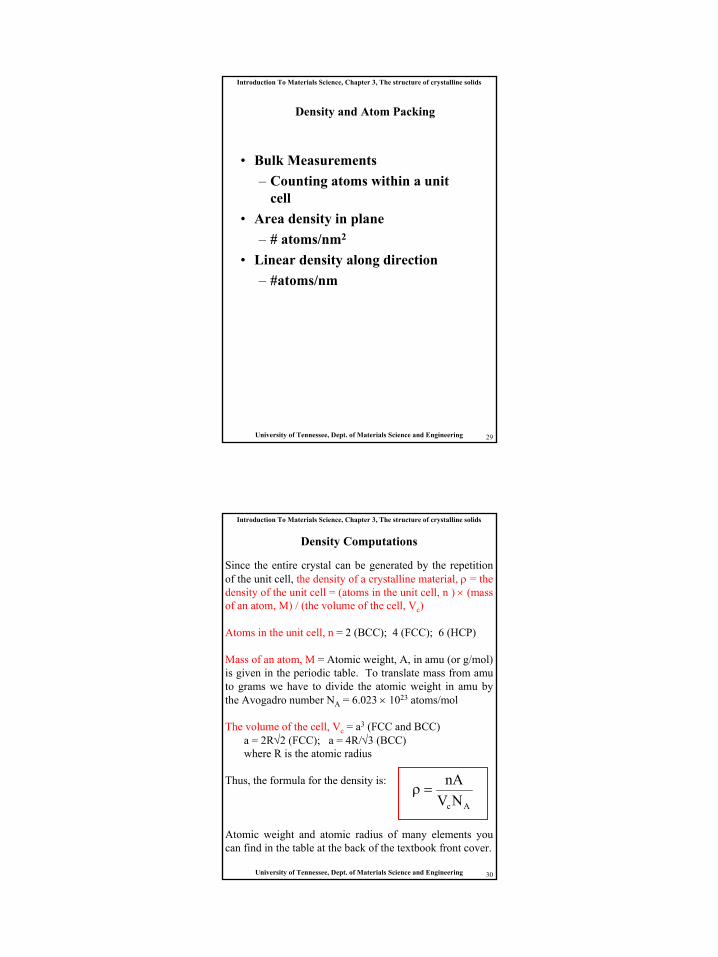
Since the entire crystal can be generated by the repetition of the unit cell, the density of a crystalline material, ρ = the density of the unit cell = (atoms in the unit cell, n ) × (mass of an atom, M) / (the volume of the cell, Vc)
Density Computations
Atoms in the unit cell, n = 2 (BCC); 4 (FCC); 6 (HCP)
Mass of an atom, M = Atomic weight, A, in amu (or g/mol) is given in the periodic table. To translate mass from amuto grams we have to divide the atomic weight in amu by the Avogadro number NA = 6.023 × 10²³ atoms/mol
The volume of the cell, Vc = a3 (FCC and BCC)a = 2R√2 (FCC); a = 4R/√3 (BCC)where R is the atomic radius
Thus, the formula for the density is:
AcNVnA
=ρ
Atomic weight and atomic radius of many elements you can find in the table at the back of the textbook front cover.
16
Introduction To Materials Science, Chapter 3, The structure of crystalline solids
University of Tennessee, Dept. of Materials Science and Engineering 31
• In polycrystalline materials, grain orientations are random, so bulk material properties are isotropic
• Some polycrystalline materials have grains with preferred orientations (texture), so properties are dominated by those relevant to the texture orientation
Polycrystalline Materials
Introduction To Materials Science, Chapter 3, The structure of crystalline solids
University of Tennessee, Dept. of Materials Science and Engineering 32
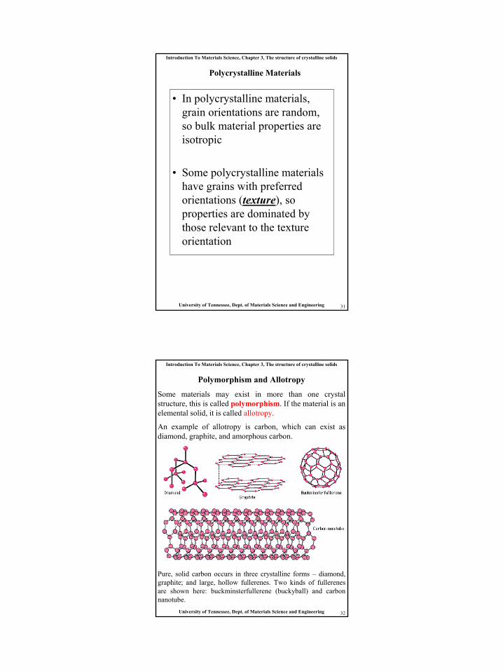
Some materials may exist in more than one crystal structure, this is called polymorphism. If the material is an elemental solid, it is called allotropy.
An example of allotropy is carbon, which can exist as diamond, graphite, and amorphous carbon.
Polymorphism and Allotropy
Pure, solid carbon occurs in three crystalline forms – diamond, graphite; and large, hollow fullerenes. Two kinds of fullerenesare shown here: buckminsterfullerene (buckyball) and carbon nanotube.
17
Introduction To Materials Science, Chapter 3, The structure of crystalline solids
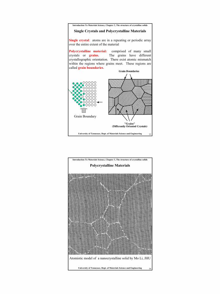
University of Tennessee, Dept. of Materials Science and Engineering 33
Single Crystals and Polycrystalline Materials
Single crystal: atoms are in a repeating or periodic array over the entire extent of the material
Polycrystalline material: comprised of many small crystals or grains. The grains have different crystallographic orientation. There exist atomic mismatch within the regions where grains meet. These regions are called grain boundaries.
Grain Boundary
Introduction To Materials Science, Chapter 3, The structure of crystalline solids
University of Tennessee, Dept. of Materials Science and Engineering 34
Polycrystalline Materials
Atomistic model of a nanocrystalline solid by Mo Li, JHU
18
Introduction To Materials Science, Chapter 3, The structure of crystalline solids
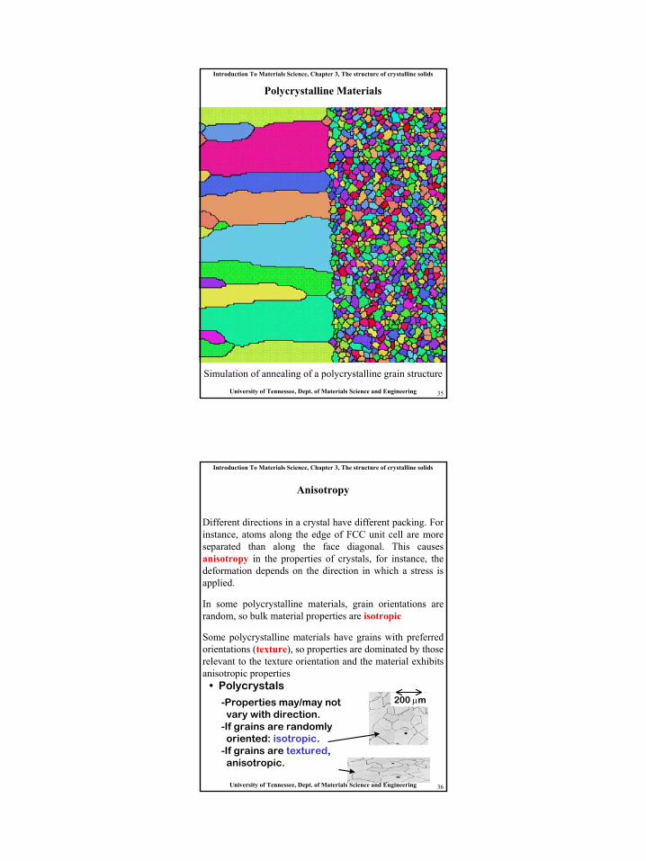
University of Tennessee, Dept. of Materials Science and Engineering 35
Polycrystalline Materials
Simulation of annealing of a polycrystalline grain structure
Introduction To Materials Science, Chapter 3, The structure of crystalline solids
University of Tennessee, Dept. of Materials Science and Engineering 36
Anisotropy
Different directions in a crystal have different packing. For instance, atoms along the edge of FCC unit cell are more separated than along the face diagonal. This causes anisotropy in the properties of crystals, for instance, the deformation depends on the direction in which a stress is applied.
In some polycrystalline materials, grain orientations are random, so bulk material properties are isotropic
Some polycrystalline materials have grains with preferred orientations (texture), so properties are dominated by those relevant to the texture orientation and the material exhibits anisotropic properties
• Polycrystals
-Properties may/may notvary with direction.
-If grains are randomlyoriented: isotropic.
-If grains are textured,anisotropic.
200 µm
19
Introduction To Materials Science, Chapter 3, The structure of crystalline solids
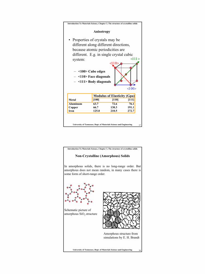
University of Tennessee, Dept. of Materials Science and Engineering 37
Anisotropy
• Properties of crystals may be different along different directions, because atomic periodicities are different. E.g. in single crystal cubic system:
– <100> Cube edges– <110> Face diagonals– <111> Body diagonals
<111>
<100>
<110>
Modulus of Elasticity (Gpa)[100] [110] [111]Metal
Aluminum 63.7 72.6 76.1Copper 66.7 130.3 191.1Iron 125.0 210.5 272.7
Introduction To Materials Science, Chapter 3, The structure of crystalline solids
University of Tennessee, Dept. of Materials Science and Engineering 38
Non-Crystalline (Amorphous) Solids
In amorphous solids, there is no long-range order. But amorphous does not mean random, in many cases there is some form of short-range order.
Schematic picture of amorphous SiO2 structure
Amorphous structure from simulations by E. H. Brandt
20
Introduction To Materials Science, Chapter 3, The structure of crystalline solids
University of Tennessee, Dept. of Materials Science and Engineering 39
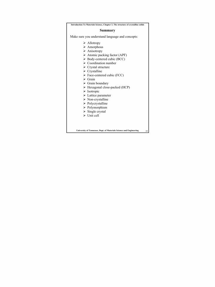
Summary
Allotropy Amorphous Anisotropy Atomic packing factor (APF) Body-centered cubic (BCC) Coordination number Crystal structure Crystalline Face-centered cubic (FCC) Grain Grain boundary Hexagonal close-packed (HCP) Isotropic Lattice parameter Non-crystalline Polycrystalline Polymorphism Single crystal Unit cell
Make sure you understand language and concepts: