chapter 3 3 facies description and interpretation 3.1 …
TRANSCRIPT

28
CHAPTER 3
3 FACIES DESCRIPTION AND INTERPRETATION 3.1 THE FACIES CONCEPT The first use of the term “facies” was introduced into geology by the Swiss
geologist Gressly (1838), who applied this term to lateral changes within time-
stratigraphic units of the Mesozoic. This term was then broadened and widely
used by Johannes Walther the sedimentologist and stratigrapher, in his “Rule
of Succession of Facies” (Walther, 1894, In: Middleton, 1973). This rule was
referred to as the Law of Correlation (or Succession) of Facies. Walther (op.
cit.) points out that there must be no major breaks (unconformities) in the
stratigraphic sequence if the principle is to be applied. The practical
application of this law is applying it to determine the relationship between
present-day sedimentary facies and their lateral distribution, with those of
vertical successions of facies in the rock record.
Subsequently, the term facies has been used more broadly, with a number of
different meanings. Moore’s (1949) definition, has been most widely accepted:
“Sedimentary facies is defined as any areally restricted part of a designated
stratigraphic unit which exhibits characters significantly different from those of
other parts of the unit” (In : Blatt et al., 1980, p. 618).
This study uses the term facies in the same sense as proposed by Middleton
(1978). The facies description is objective, based upon observations of
physical features in the rocks. Middleton (op. cit.) outlined: “The key to the
interpretation of facies is to combine observations made on their spatial

29
relations and internal characteristics (lithology and sedimentary structures)
with comparative information from other well-studied stratigraphic units, and
particularly from studies of modern sedimentary environments” (p. 323-325).
This definition is similar to that used by Walker and James (1992) who relate
facies models to sequence stratigraphy.
Miall (1977, 1978) applied the concept of facies analysis to identify a variety of
fluvial systems, which were then successfully applied to submarine -fan
systems. This concept combines individual lithofacies at a macroscale and
microscale, and attempts to erect models used in the identification and
description of depositional systems.
Based on Miall’s (1977, 1978) work, Le Blanc Smith (1980) proposed a logical
letter code for facies nomenclature with the main objective of standardizing the
facies types found in the northern Karoo Basin, Witbank Coalfield. These
facies were identified from field exposures, and drill holes. The definition of
the facies was based on lithology, sedimentary structures, biogenic structures
and stratigraphically distinctive minerals, such as glauconite, which is of
significant importance for this study, as a stratigraphic marker mineral
occurring above the No. 4 and No. 5 seams.
For this study, most of the data used for defining the facies, came from
borehole logs and borehole core. It is therefore, a subsurface investigation.
One of the main aspects used in defining each lithofacies was grain size
variation. According to standard international practice, the grain size was
defined by applying the Wentworth scale illustrated in (Table 3.1).

30
WENTWORTH GRAIN SIZE SCALE
Limiting particle diameter
mm φ units Size class
2048 - 11 Very large
1024 - 10 Large
512 - 9 Medium
256 - 8 Small
128 - 7 Large
64 - 6 Small
1 0 Very coarse
µm
½ + 1 500 Coarse
¼ + 2 250 Medium 1/8 + 3 125 Fine 1/16 + 4 62 Very fine 1/32 + 5 31 Very coarse 1/64 + 6 16 Coarse 1/128 + 7 8 Medium 1/256 + 8 4 Fine 1/512 + 9 2 Very fine
Boulders
Cobbles
Pebbles
Granules
Sand
Silt
Clay
G R
A V
E L M
U D
Table 3.1. Wentworth grain size scale (modified after Davis, 1983, p. 7).

31
3.2 SEDIMENTARY FACIES
Although this study focuses primarily on the No. 4 seam and associated facies,
all of the facies types encountered in the study area are presented below for the
sake of completeness. These include lithofacies from the basal Dwyka Group
tillites to the argillaceous units of the Volsksrust Formation, overlying the
Vryheid Formation. However, the lithofacies directly above No. 4 seam, are
discussed in greater detail, rather than those of the entire stratigraphic column
present.
3.3 CONGLOMERATE FACIES The coarse-grained lithofacies includes clast-supported and matrix-supported
rocks in the study area, with a mean grain diameter greater than 4mm (Table
3.1).
Three conglomerate sub-facies are recognized in the study area. These are
defined by the presence or absence of sedimentary structures, i.e., whether
they are matrix supported conglomerate, massive or cross-bedded small-
pebble conglomerate.
3.3.1 Diamictite sub-facies DESCRIPTION
The diamictite sub-facies or matrix-supported conglomerate lithofacies is
located at the base of the Karoo Supergroup, and forms a thin layer of

32
sedimentary rock overlying pre -Karoo basement lithologies (Tankard et al.,
1982). The diamictite forms part of the Dwyka Group. The diamictite consists
of clasts, which are diverse in shape and size and range from rounded to very
angular. The clast colours are commonly red, grey-olive, brown and blue
(Figure 3.1). Almost all are exotic, extrabasinal in origin. The matrix ranges
from dark-grey mudstone to light-grey siltstone. The diamictite is overlain by
massive and cross-bedded conglomerate or coarse to very coarse cross-
bedded sandstone. This sub-facies is variable in thickness but has a
maximum thickness of 30m in palaeovalleys. The thickening of diamictite in
the study area is confined to the south-western section.
INTERPRETATION The Karoo Basin diamictites originated as gravity driven debris flows, slumps
and glacial fill deposits. Le Blanc Smith (1980) interpreted the Dwyka
diamictites in the Witbank Coalfield, as being of terrestrial glacial origin.
Winter (1985), Cairncross (1986) and Cadle (1995) came to similar
conclusions with respect to these basal diamictites.
3.3.2 Massive conglomerate sub-facies
DESCRIPTION
The massive conglomerate sub-facies can be distinguished on the basis of the
absence of sedimentary structures, poor sorting and proportions of quartz and
feldspar clasts vs. matrix. When the conglomerate clasts are well-sorted it
tends to be clast-supported, and the clasts are well rounded, with a high

33
Figure 3.1. Diamictite sub-facies comprising a siltstone matrix and
extrabasinal pebbles.

34
sphericity. If any matrix is however present, it is generally well -sorted and
composed of coarse silt or fine sand. This sub-facies (Figure 3.2) is most
commonly interbedded with the cross-bedded conglomerate sub-facies (see
sub-facies 3.3.3).
The second conglomerate sub-facies is a matrix-supported, small-pebble
conglomerate. This has a high percentage of siltstone matrix and a wide range
of clast sizes, varying between 2mm and 5cm in diameter. Figure 3.3 is Folk's
(1974), roundness (sphericity) scale, showing both high and low spherically
shaped particles ranging from very angular to well rounded and its pattern is
associated with clast composition in the study area. Pebbles are composed of
amygdaloidal lava, siltstone, coal spar, quartz, chert and granite. This sub-
facies is predominantly upward-fining. The matrix-supported conglomerate
sub-facies compromises linear bodies over 40m thick, along palaeovalley’s.
The matrix-supported, small-pebble conglomerate (Figure 3.4) occurs
stratigraphically between No. 4 seam and No. 4 A seam.
INTERPRETATION
This sub-facies is interpreted from deposition under high -energy aqueous flow
conditions. Adequate flow velocities are required to winnow out the finer
matrix, particularly with reference to the clast-supported sub-facies. Within
gravels, clasts are unable to respond to fluid stresses (Harms et al., 1982).
Massive and crudely stratified gravels have been described by Gustavson
(1975), Miall (1977, 1978), states that, a high matrix content is caused by
high-discharge events, followed by rapid deposition with little or no reworking.
Glacio-fluvial processes are inferred from the association of massive
conglomerate sediments with Dwyka Group diamictites. Massive, matrix-
supported conglomerate (diamictite) commonly forms by gravity flow

35
Figure 3.2. Clast supported sub-facies of the conglomerate facies
containing small-pebbles of quartz and feldspar.

36
Figure 3.3. Roundness and sphericity scale (modified after Folk, 1974).
processes, such as debris flows (Nicholas, 1999). Little or no reworking
preserves the high matrix content and results in very poor sorting of the clasts.

37
Figure 3.4. Matrix-supported sub-facies of the conglomerate facies
comprising quartz and feldspar grains. The unit is coarsening-
upward.
38
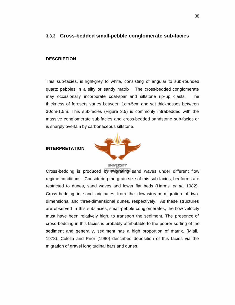
3.3.3 Cross-bedded small-pebble conglomerate sub-facies
DESCRIPTION
This sub-facies, is light-grey to white, consisting of angular to sub-rounded
quartz pebbles in a silty or sandy matrix. The cross-bedded conglomerate
may occasionally incorporate coal-spar and siltstone rip-up clasts. The
thickness of foresets varies between 1cm-5cm and set thicknesses between
30cm-1.5m. This sub-facies (Figure 3.5) is commonly intrabedded with the
massive conglomerate sub-facies and cross-bedded sandstone sub-facies or
is sharply overlain by carbonaceous siltstone.
INTERPRETATION
Cross-bedding is produced by migrating sand waves under different flow
regime conditions. Considering the grain size of this sub-facies, bedforms are
restricted to dunes, sand waves and lower flat beds (Harms et al., 1982).
Cross -bedding in sand originates from the downstream migration of two-
dimensional and three-dimensional dunes, respectively. As these structures
are observed in this sub-facies, small-pebble conglomerates, the flow velocity
must have been relatively high, to transport the sediment. The presence of
cross -bedding in this facies is probably attributable to the poorer sorting of the
sediment and generally, sediment has a high proportion of matrix. (Miall,
1978). Colella and Prior (1990) described deposition of this facies via the
migration of gravel longitudinal bars and dunes.

39
Figure 3.5. Cross-bedded small -pebble conglomerate sub-
facies comprising poorly-sorted quartz and feldspar grains.

40
3.4 SANDSTONE FACIES
The sandstone facies is composed of clastic grains ranging in size from
0. 0625mm to 2mm (Table 3.1).
3.4.1 Massive sandstone sub-facies
This sub-facies can be subdivided on the basis of textural criteria and colour.
The sandstone is well-sorted with grains that vary from fine sand (0,25mm) to
very coarse-grained (2mm) sand. The colours vary between white and light-
grey, green and brown (Figures 3.6 and 3.7). The massive sandstone sub-
facies is commonly intrabedded with siltstone, cross-bedded and wave-ripple
cross -laminated sandstone. Stratigraphically, the well-sorted massive
sandstone occurs immediately above the No. 2, No. 3 No. 4 and No. 5 coal
seams.
INTERPRETATION
Blatt et al. (1980) have shown that some sandstone that appears to be
lacking in textural features, do in fact have lamination or cross-lamination,
when x-rayed. However, this facies in the study area appears to be massive,
with no structure present, or it can be reworked.
Colella and Prior (1990) showed that secondary destructive reworking
processes, such as bioturbation, could destroy primary structures thereby
producing homogenized sediment. Colella and Prior (op. cit.) further

41
Fig
ure
3.6
. (A
) W
ell-s
ort
ed c
oar
se- t
o m
ediu
m-g
rain
ed s
and
sto
ne.
Th
e ab
sen
ce o
f str
uctu
re a
ppea
rs to
be
pri
mar
y. (
B) C
oar
se s
and
sto
ne
wit
h s
hal
e ri
p-u
p c
last
s.
(A)
(B)

42
Fig
ure
3.
7
Mas
sive
sa
nd
sto
ne
sub
-fac
ies,
(A
) Ill
ust
rate
s w
ell-
sort
ed,
fin
e-g
rain
ed
san
dst
on
e, (
B)
Wel
l-so
rted
, m
ediu
m-g
rain
ed s
and
sto
ne.
(A)
(B)

43
demonstrated tha t massive sandstone can be formed either by rapid
deposition from suspension, contemporaneous deformation or by bioturbation.
The lack of grading and fluid -escape structures would suggest that the
sedimentation rate was low. The poorly-sorted massive sandstone of this
study, containing a high siltstone matrix, formed from the destruction of
bedding through bioturbation by organisms, and it can be associated with
bioturbated siltstone and sandstone facies (Cadle, 1995). The massive
sandstone sub-facies, in the study area is closely associated with the flaser-
laminated sandstone sub-facies, the interlaminated sandstone-siltstone facies,
and the lenticular-laminated siltstone sub-facies, particularly where they are
bioturbated.
3.4.2 Planar cross-bedded sandstone sub-facies
DESCRIPTION
This sub-facies is composed of grey-white arkosic sandstone, with minor
amounts of silt and mica. The grain size of this facies is fine to very coarse-
grained sandstone, and the sandstone is structured by planar cross-bedding.
Set boundaries are flat, and foresets are graded, from coarse- to medium-
grained sand, with a generally steep foreset angle of between 20° and 30°.
Set heights vary between 20cm and 1.5m (Figure 3.8). Stratigraphically, this
facies is situated below the No. 2 seam and above the No. 4 seam.

44
Fig
ure
3.8
. (
A)
Pla
nar
cro
ss-b
edd
ed s
and
sto
ne
sub
-fac
ies.
Th
e cr
oss
-bed
din
g i
s d
efin
ed b
y fi
nin
g-
up
war
d f
ore
sets
, (B
) P
lan
ar c
ross
-bed
din
g w
ith
cm
-intr
abed
ded
co
ng
lom
erat
e la
g a
nd
co
al-s
par
len
ses
at th
e to
p.
(A)
(B)

45
INTERPRETATION
Planar cross-bedding is produced by the downstream migration of two-
dimensional bedforms (Harms et al., 1982). Blatt et al. (1980) stated that the
mechanism that produces most cross-bedding is encroachment by
avalanching down the lee slope of dunes, small deltas, ripples, fans or bars.
The size of the sedimentary structures in this sub-facies suggests the latter
(Harms et al., 1982).
3.4.3 Trough cross-bedded sandstone sub-facies
DESCRIPTION
This sub-facies compromises grey-white, fine to coarse-grained sandstone
with a high silt and mica component. The trough cross -bedding is defined by
concave erosional scours filled by curved foreset layers that define the
structure. Thin gravel lags are frequently present at the base of sets. Set
heights vary between 10-50cm. Foreset laminae are characteristically concave
upward. This sub-facies (Figure 3.9) is commonly intrabedded with the planar
cross -bedded sandstone facies or is intrabedded with wave-ripple laminated
sandstone sub-facies. This trough cross-bedded sandstone sub-facies, occurs
stratigraphically below the No. 2 and, above No. 4 seams.

46
Figure 3.9. Trough cross-bedded sandstone sub-facies defined by
scoured surfaces, with concave laminae.

47
INTERPRETATION
Harms et al. (1975) states that, hydrodynamically, trough -cross bedded
sandstone forms from the downstream migration of three-dimensional dunes.
These multidimensional bedforms migrate at relatively high flow velocities, the
uppermost part of the lower flow regime. However, the arkosic variant of sub-
facies often overlies the planar cross-bedded sandstone and possibly
represents the migration of dunes over sandwaves (Harms, op. cit.). This sub-
facies is commonly documented at relatively high velocities, within the lower
flow regime (Rust et al., 1984; Harms, op. cit .).
3.4.4 Planar laminated sandstone sub-facies
DESCRIPTION
This sub-facies is characterized by light-grey, medium- to very fine-grained
sandstone containing minor silt, mica and heavy minerals. This facies
distinguishing feature is that sandstone laminae are parallel to sub-parallel
with the underlying set boundaries. This sub-facies ranges between 5-50cm in
thickness. Individual laminae vary in thickness from a few millimeters to 1cm.
The sub-facies (Figure 3.10) is commonly intrabedded with planar cross-
bedded and cross-laminated sandstone or with wave-rippled and trough cross-
bedded sandstone. Stratigraphically, this sub-facies occurs towards the top of
coarsening-upward sedimentary units, below No. 3 and No. 5 seams. The sub-
facies also overlies cross-bedded sandstone below the No. 2 and above No. 4
seams. This sub-facies is often related to the upper-most parts of fining-
upward cycles.

48
Figure 3.10. Planar laminated sandstone sub-facies illustrating well
defined horizontal to sub-horizontal laminae.

49
INTERPRETATION
The interpretation of planar horizontal or nearly horizontally laminated
sandstone can be reviewed in several ways. Planar lamination includes
sediment particles originating via suspension settling in a fluid, in the absence
of any currents or lateral transportation. Harms et al. (1982) stated that planar
lamination can be produced under different conditions such as unidirectional
flows in strong currents, unidirectional flows with low velocities, settling fine-
grained sediment and symmetrical oscillatory flows when velocities are large.
Where the facies overlies trough and planar cross-bedded sandstone no
graded lamination is present. This suggests deposition of sediment at high
velocities as documented by Cadle (1995). Therefore, this facies originates
under upper flow regime conditions (Harms et al., 1982), where sediment is
transported laterally, as horizontal layers, under high flow velocities.
3.4.5 Cross-laminated sandstone sub-facies
DESCRIPTION
This sub-facies comprises cross -laminated fine- to medium-grained grey-white
sandstone with minor siltstone and mica present. The set size of laminae
ranges between 0,5-5cm, and sets that are less than 1cm thick are estimated
to have a cross-sectional dimension of 5 -10cm. There are two different types,
which can be distinguished. The first bedding style is cross -lamination where
laminae are concave and convex upwards. The second type of bedding is
represented by cross-laminae which are tabular parallel to flow, as well as
transverse to flow and concave upward as shown in Figure 3.11.
Stratigraphically, the first type of cross-lamination is present in the sandstone

50
Fig
ure
3.
11.
(A)
Cro
ss-la
min
ated
sa
ndst
one
sub
-fac
ies,
w
ave-
rip
ple
la
min
atio
n,
cap
ped
b
y
silts
ton
e,
(B)
Cro
ss-l
amin
ated
sa
nd
sto
ne-
silt
sto
ne
wit
h
som
e so
ft-s
edim
ent
def
orm
atio
n
stru
ctu
res
pre
sen
t.
(A)
(B)

51
intervals between the No. 2 and No. 3 seams and the No. 4 and No. 5 seams.
The second type is situated below the No. 2 and above the No. 4 seams.
INTERPRETATION
Harms et al. (1975) stated that oscillatory flow produced by waves interacts
with the sediment substrate and produces symmetrical wave ripples. These
ripples are typically symmetrical or slightly asymmetric, with peaked crests
and rounded troughs. Harms (op. cit.) noted that symmetric or wave ripples
with a spacing of 10cm-30cm are common in a shallow marine environment,
while closely spaced wave ripples between 1cm-3cm are typical of shallow
ponded water. Sandstone structured by small-scale trough cross-lamination is
present towards the top of upward-fining sandstones between the No. 2 and
No. 4 depositional sequences.
The asymmetric or current ripples (Figure 3.12) are characterized by low relief
and linear crests. Rieneck and Singh (1980) stated that asymmetrical ripples
are commonly two-dimensional. According to Reineck and Singh (op. cit.) the
presence of bifurcating ripples may indicate interference patterns produced by
waves interacting with currents
Cadle (1995) noted that the presence of small-scale oscillation-ripple
lamination in the Vryheid Formation suggests that wave processes were an
important factor in reworking fine-grained sand. Small-scale trough cross-
laminated sandstone commonly represents the migration of current ripples
over the steep side of larger dunes. These ripples are formed due to a
reduction in water depth, velocity and grain size.

52
Figure 3.12. Cross -lamination produced by current ripples.

53
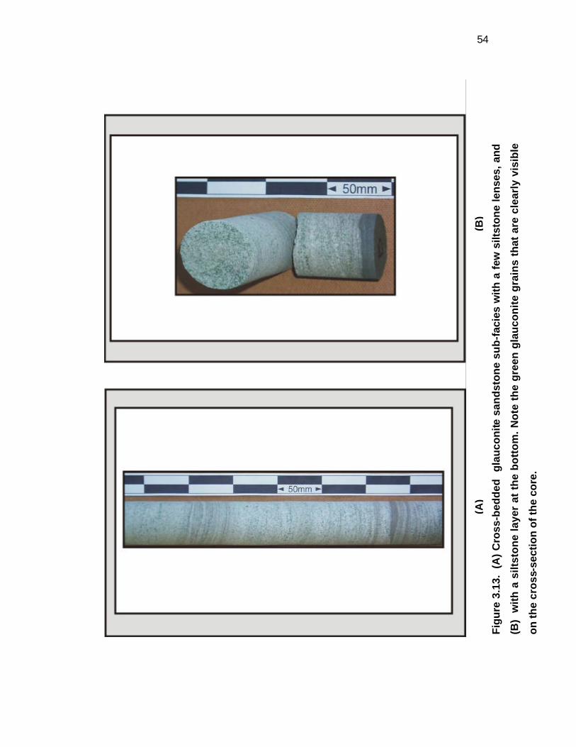
3.4.6 Glauconite sandstone sub-facies
DESCRIPTION
This sub-facies is easily defined lithologically, as it has a characteristic green-
flecked colour, with fine to granular green glauconite g rains. The sandstone is
well-sorted, fine- to medium-grained. The glauconite-bearing facies thickness
ranges from a few centimetres to over 15m. Glauconite forms granules, and
crudely elliptical grains, averaging one -half of a millimetre in diameter (Figure
3.13). The glauconite sandstone facies is a useful stratigraphic marker above
the No. 4 and No. 5 seams, presenting a valuable correlation between the coal
seams, and even between coal facies (Cadle et al., 1995).
INTERPRETATION
Pettijohn (1957) no ted that glauconite is presently forming in deep and shallow
marine waters. Takahashi (1939) states "Glauconite seems to be formed
under marine conditions by a process of hydration of silica and subsequent
absorption of bases and loss of alumina. Glauconite may originate from a
number of primary materials, such as faecal pellets, clayey substances filling
cavities of foraminifera, radiolaria and tests of other marine organisms, or from
silicate mineral substances, such as volcanic glass, feldspar, mica or
pyroxene. In salt water ….. the primary substances during glauconitisation
lose alumina, silica and alkali’s except potash, and green ferric iron. Sea
water, therefore, seems essential …….". Cloud (1955) stated that glauconite
is formed only in marine waters of normal salinity, whose formation is
facilitated by the presence of organic matter. However, glauconite is now
54
Fig
ure
3.1
3. (
A)
Cro
ss-b
edd
ed
gla
uco
nite
san
dst
on
e su
b-f
acie
s w
ith
a f
ew s
iltst
on
e le
nse
s, a
nd
(B)
wit
h a
silt
sto
ne
laye
r at
th
e b
ott
om
. No
te t
he
gre
en g
lau
con
ite
gra
ins
that
are
cle
arly
vis
ible
on
th
e cr
oss
-sec
tio
n o
f th
e co
re.
(B)
(A)

55
known to also form in non-marine lacustrine settings (McRae, 1972). It forms
from micaceous minerals or pelagic muds rich in iron. However, the bulk of
glauconite does originate under marine conditions. Winter (1985) described
ubiquitous and widespread glauconite beds in the northeastern Karoo Basin.
This sub-facies close association with cross-laminated sandstone may be
indicative of shallow water environments. The presence of glauconite-bearing
sandstone immediately above the No. 4 and the No. 5 seams, suggests that
the sediment was deposited during high-stand, transgressive marine episodes.
The close association of marine bioturbation (see facies 3.7.3) also supports
this conclusion.
3.4.7 Bioturbated sandstone sub-facies
DESCRIPTION
This sub-facies compromises sandstone ranging from fine - to coarse-grained
and contains significant percentages of silt, which gives the facies a grey
colour (Figure 3.14). The sedimentary structures may be partially to
completely destroyed by the activity of organisms. Where present, the primary
structures are cross- and flaser-laminated sandstone, and interlaminated
sandstone-siltstone. Bioturbation occurs as vertical and, less commonly, as
horizontal burrows. Where bioturbation is very intense, individual trace fossils
cannot be identified. Stratigraphically, this sub-facies occurs toward the top of
coarsening-upward sequences, between the No. 2 and No. 3 seams. It is also
present within sheet sandstones above the No. 2, No. 4 and No. 5 seams.

56
Figure 3.14. Bioturbated sandstone sub-facies, with
interlaminated dark-grey siltstone. Both lithologies have been
intensively bioturbated.

57
INTERPRETATION
After deposition, sedimentary strata may be disturbed by organisms. These
structures are termed biogenic trace fossils (Basan, 1978). This sub-facies is
very important, as it represents trace fossils that are usually grouped into
depth-controlled communities (Seilacher, 1967), although other factors such
as salinity, water temperature, and food supply also control ichnofacies
activity.
Trace fossils may be used as palaeoenergy indicators, according to whether
the animal was moving up, down or cross-current and resting tracks may have
a preferred orientation in the Vryheid Formation. Horizontal burrows are
indicative of low-energy environments, such as interdistributary bays, in which
significant percentages of silt were deposited (Stanistreet et al., 1980).
Trace fossils may be used to determine rates of sedimentation. Vertical,
unbranched burrows, such as Skolithos (Seilacher, 1967) and Siphonichnus
Eccaensis (Stanistreet et al., 1980) indicate a rapid sedimentation rate where
organisms had to burrow vertically to keep pace with the depositing sediment.
The distribution of this facies between the No. 2 and No. 3 seams, which
contains Siphonichnus Eccaensis traces, has been interpreted by Stanistreet
(op. cit.) and Winter (1985) to have been deposited during high rates of
deposition. In some strata, the bioturbation is intense (Figure 3.14) suggesting
that although sedimentation ra tes were high, the organisms had sufficient time
to totally rework their substrata.
58
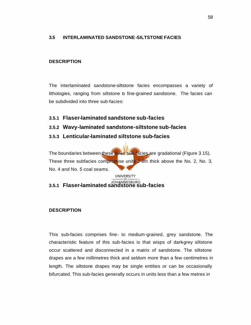
3.5 INTERLAMINATED SANDSTONE -SILTSTONE FACIES
DESCRIPTION
The interlaminated sandstone-siltstone facies encompasses a variety of
lithologies, ranging from siltstone to fine-grained sandstone. The facies can
be subdivided into three sub-facies:
3.5.1 Flaser-laminated sandstone sub-facies
3.5.2 Wavy-laminated sandstone-siltstone sub-facies
3.5.3 Lenticular-laminated siltstone sub-facies
The boundaries between these three sub-facies are gradational (Figure 3.15).
These three subfacies compromise units 2-3m thick above the No. 2, No. 3,
No. 4 and No. 5 coal seams.
3.5.1 Flaser-laminated sandstone sub-facies
DESCRIPTION
This sub-facies comprises fine- to medium-grained, grey sandstone. The
characteristic feature of this sub-facies is that wisps of dark-grey siltstone
occur scattered and disconnected in a matrix of sandstone. The siltstone
drapes are a few millimetres thick and seldom more than a few centimetres in
length. The siltstone drapes may be single entities or can be occasionally
bifurcated. This sub-facies generally occurs in units less than a few metres in

59
Figure 3.15 Block diagram showing (a) Flaser, (b) Wavy, and (c)
Lenticular lamination (modified after Davis,1983).

60
thickness. The sub-facies can be distinguished from the other sub-facies on
the basis that siltstone drapes are discontinuous over several centimetres
(Figure 3.16).
INTERPRETATION
Flaser lamination can form by thin, incomplete mud laminae trapped in ripple
troughs and draping ripple crests, during periods of slack water (Blatt et al.,
1980). Flaser lamination is most commonly developed under low-energy
conditions (Davis, 1983). Flaser lamination therefore forms by deposition of
sand and silt during episodic events of bedload traction and suspension
settling, respectively.
Flaser-lamination forms where the sediment supply is rhythmic or periodic
(Winter, 1985). Flaser lamination is described by Le Blanc Smith (1980) from
the Witbank Coalfield. He described periods of current activity during which
sand is transported and forms ripples, while mud is held in suspension. When
the current abates, the suspended sediment settles into troughs and over the
ripples. During renewed current flow, previously formed ripple crests are
eroded and the next layer of sand is deposited, burying the underlying ripple
with mud flasers in the ripple troughs.
3.5.2 Wavy-laminated sandstone-siltstone sub-facies
DESCRIPTION
This sub-facies comprises interlaminated sandstone and siltstone. The

61
Figure 3.16. Flaser laminated sandstone within the cross-laminated
sandstone sub-facies.

62
sandstone is fine- to medium-grained, and white -grey, while the siltstone is
dark-grey, highly carbonaceous and micaceous. The sandstone laminae vary
in thickness between a few millimetres to 5cm. Dark-grey siltstone laminae
vary between 2mm-3cm in thickness and drape over rippled sandstone
surfaces. This sub-facies (Figure 3.17) is characterized by undulatory (wavy)
bedding surfaces that separate individual sets seldom more than several
millimetres thick.
INTERPRETATION
The wavy-laminated sandstone-siltstone forms as a result of alternating
episodes of suspension settling of silt and bedload deposition of sand (Harms
et al., 1975). These two sediments are present in more or less equal quantities
and this sub-facies is an intermediate stage between the flaser and lenticular-
laminated sub-facies. Sand is either transported along the bed by current flow,
forming asymmetric ripples, or surface wave action reworks the sandy
substrate into symmetrical ripple forms. During periods of low wave activity
and reduced current flow, mud settles from suspension, draping the previously
formed ripples, thereby producing wavy-laminated sub-facies (Reinecke and
Singh, 1980).
3.5.3 Lenticular-laminated siltstone sub-facies
DESCRIPTION
The lenticular-laminated siltstone, consists of dark-grey carbonaceous
siltstone with thin, interbedded sandstone lenses up to 3cm thick. Lenses vary
from 10mm to 20cm in length.

63
Fig
ure
3.
17.
(A)
Wav
y-l
amin
ated
sa
nd
sto
ne
-silt
ston
e su
b-f
acie
s an
d
ero
sio
nal
co
nta
ct,
(B)
San
dst
on
e-s
iltst
on
e fa
cies
illu
stra
tin
g w
ell d
efin
ed h
ori
zon
tal l
amin
ae.
(A)
(B)

64
Contacts between sandstone and siltstone are sharp, indicating distinct
episodes of alternating silt and sand deposition. This sub-facies (Figure 3.18)
generally overlies the carbonaceous siltstone sub-facies and underlies the
wavy-laminated sandstone-siltstone facies of No. 2, No. 3 No. 4 and No.5 coal
seams.
INTERPRETATION
This sub-facies consists of small isolated lenses of sandstone contained in
siltstone. These sedimentary structures are produced when there is
insufficient sand available. Isolated ripples (starved ripples) form on the
muddy substrate and become covered by more mud, thereby being preserved
(Harms et al., 1975). This sub-facies is thus a result of suspension settling of
mud, coupled with current flow that generates the isolated sandy ripples.
This spectrum of bedding is dependent on conditions such as availability of
both sand and mud and alternation with slack water conditions when silt and
clay are deposited (Reineck and Singh, 1980; Winter, 1985).

65
Fig
ure
3.1
8.
(A)
Len
ticu
lar-
lam
inat
ed s
iltst
on
e w
ith
san
dst
on
e le
nse
s, (
B)
Th
e sa
me
sub
-faci
es w
ith a
2cm
dia
gen
etic
pyr
ite
no
du
le.
(A)
(B)

66
3.6 SILTSTONE FACIES
Primary siltstone comprises a relatively small percentage of the Highveld
Coalfield stratigraphic column. The siltstone is usually massive and/or
bioturbated, and is commonly intrabedded with sandstone. Interbeded sets of
granule conglomerate, sandstone, and siltstone display lenticular-lamination
(Figure 3.19).
3.6.1 Gravelly siltstone sub-facies
DESCRIPTION
This sub-facies comprises grey to dark-grey carbonaceous siltstone, with
significant sand and gravel content, and particle sizes ranging between 2-
15mm (Figure 3.20). These coarse grains are poorly sorted, and may be
horizontally laminated throughout the siltstone matrix. The sub-facies occurs
above the No. 4 seam, within the carbonaceous siltstone sub-facies and is
occasionally overlain by the lenticular-laminated siltstone. This sub-facies is a
good stratigraphic marker horizon above the No. 4 Seam.
INTERPRETATION
Below No. 1 seam in the Witbank Coalfield, Le Blanc Smith (1980) has
interpreted cyclical stacking of depositional couplets to be caused by seasonal
sedimentation. A likely interpretation of this sub-facies is that of periodic debris

67
Figure 3.19. Siltstone facies. This core sample contains
interlaminated sandstone-siltstone at the top.

68
Figure 3.20 Gravelly siltstone sub-facies.

69
rain (Le Blanc Smith, op. cit .) of sand-sized and gravel-sized sediment onto
the underlying silty substrata. In the basal portion of the Vryheid Formation,
floating ice with entrapped sediment would melt, causing this coarse, poorly-
sorted clastic sediment to rain down onto the basin floor (Le Blanc Smith,
1980; Cairncross, 1986). It has been suggested by Cairncross (1979) that this
facies in the Witbank Coalfield, where it occurs above the No. 4 seam, may
have been deposited by organic rafting. If these rafts began to fragment or
became disturbed, the clastic material would become liberated and settle out
into the underlying substrata.
3.6.2 Glauconite siltstone sub-facies
DESCRIPTION
This sub-facies comprises a dark-grey to grey-brown siltstone. The glauconite
is present as anhedral matrix-filling material. The glauconite tends to be
associated with bioturbation and carbonaceous organic debris. This sub-
facies is commonly massive, but it can display some horizontally laminated
sandstone interbeds and lenticular lamination. The thickness of this sub-facies
averages a few meters and is stratigraphically approximately 20m above the
No. 4 and 5 seams.
INTERPRETATION
Glauconite is a green hydrous potassium iron phyllosilicate mineral, and is
associated with sedimentary rocks of marine origin. The presence of
glauconite most commonly suggests marine settings and sediments (Pettijohn,

70
1957). The repetitive occurrence of glauconite, in the Highveld Coalfield study
area, is found in the borehole core directly above No. 4 seam. Le Blanc Smith
(1980) stated that the close association of pelletiferous glauconite and
bioturbation structures in the Witbank Coalfield is suggestive of the
replacement of faecal pellets by glauconite.
3.6.3 Bioturbated siltstone sub-facies
DESCRIPTION
This sub-facies comprises dark-grey bioturbated siltstone with a lesser
percentage of sand. Horizontal burrows of Cruziana and Zoophycos
ichnofacies assemblage (Seilacher, 1967) are the most common ichnofacies
but there are also vertical and oblique burrows. Most of the vertical burrows
have been identified as Siphonichnus Eccaensis (Stanistreet et al., 1980).
The horizontal trails have not been specifically identified because they are
difficult to examine in borehole core. However, they fall within the Cruiziana
assemblage of feeding trails (Seilacher, op. cit.). This sub-facies is
lithostratigraphically associated with the glauconite sub-facies above the No. 4
and 5 seams.
INTERPRETATION
Stanistreet (op. cit.) stated that the bioturbated siltstone sub-facies is
indicative of deposition, from suspension settling under quiescent conditions.
The presence of horizontal ichnofacies in the silty sediments implies that the
trails were made preferentially in low-energy settings. Similar bioturbation from

71
delta-front and crevasse-splay palaeoenvironments in the Vryheid Formation
has been described by Christie (1988). The trace fossils and their association
with coal seams imply that these sediments accumulated in low-energy
environments. The bioturbated siltstone suggests suspension deposition in a
low-energy environment, and the presence of horizontal burrows support this
interpretation. Cadle (1995) described bioturbation in the Vryheid Formation,
stating that the association of trace fossils with carbonaceous siltstones
adjacent to coal seams implies that these sediments are also accumulated in
low-energy environments.
3.6.4 Carbonaceous siltstone sub-facies
DESCRIPTION
This sub-facies comprises dark-grey to black carbonaceous and micaceous
siltstone (Figure 3.21). The sub-facies is typically massive or may be vaguely
horizontally laminated. Finely disseminated pyrite, crystalline pyrite and
Glossopteris plant leaves are common in this sub-facies. Stratigraphically,
this sub-facies appears above the No. 4 seam and varies in thickness between
a few cm to less than 4m. The carbonaceous siltstone sub-facies has
occasional interbeds of coarsening-upward, fine -grained siltstone-sandstone.
INTERPRETATION
This sub-facies is formed by suspension settling of silt, under quiescent
conditions, most likely in paralic or continental settings where terrestrial
vegetation contributed to the carbonaceous content.

72
Figure 3.21. Carbonaceous siltstone sub-facies.
73
Occasional higher energy events generated the scattered interbeds of
sandstone. Within the same sub-facies Cairncross (1979) identified
Glossopteris leaves and Lycopodium and Phyllotheca stems in the Witbank
Coalfield. This abundance of terrestrial organic debris suggests that deposition
of this sub-facies occurred terrestrially, under relatively shallow water
conditions. The fine-grained sandstone may have been deposited under
slightly higher energy conditions.
Cadle (1995) described the presence of this sub-facies in the Witbank
Coalfield extensively at the base of coarsening-upward sequence, above the
No. 2, No. 4, No. 5 and No. 6 seams. This facies implies low-energy
deposition following transgression, as it is laterally distributed at the base of
coarsening-upward sequences.
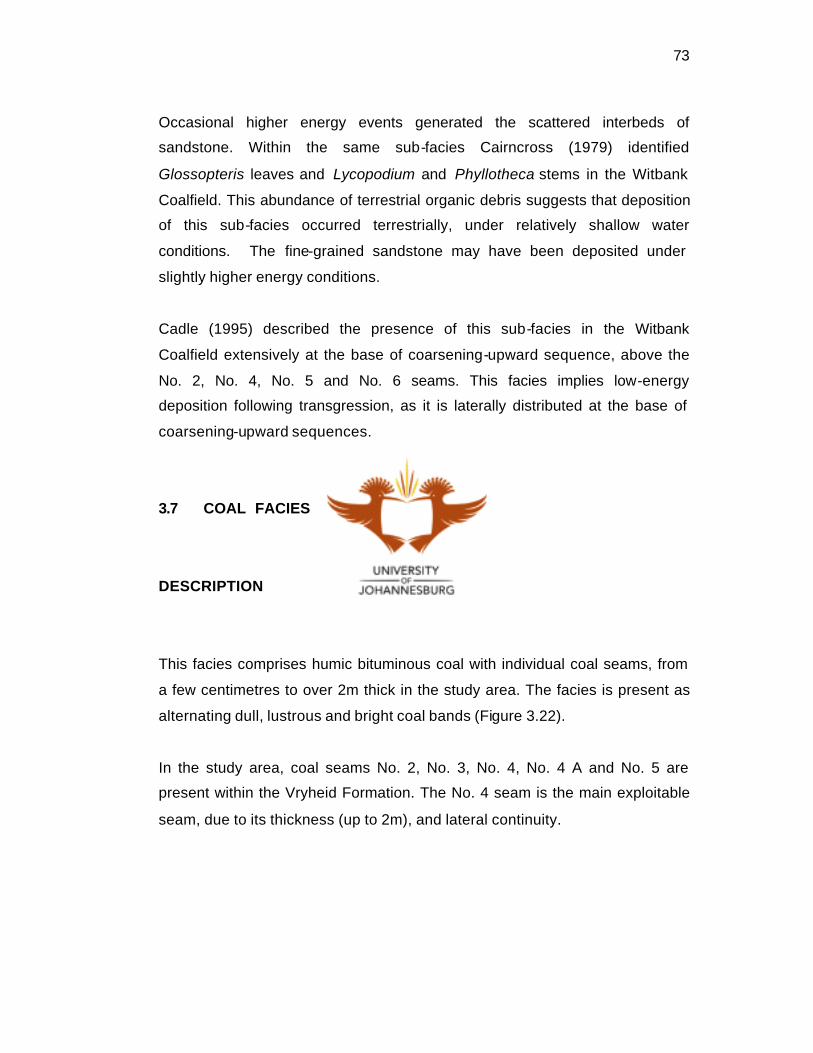
3.7 COAL FACIES
DESCRIPTION
This facies comprises humic bituminous coal with individual coal seams, from
a few centimetres to over 2m thick in the study area. The facies is present as
alternating dull, lustrous and bright coal bands (Figure 3.22).
In the study area, coal seams No. 2, No. 3, No. 4, No. 4 A and No. 5 are
present within the Vryheid Formation. The No. 4 seam is the main exploitable
seam, due to its thickness (up to 2m), and lateral continuity.

74
Figure 3.22. No. 4 seam coal facies at New Denmark showing dull
and bright bands.

75
INTERPRETATION
Coal forms from peat that has accumulated from organic debris under water-
logged conditions. After burial, peat becomes transformed, with increasing
temperature and pressure, to become lignite, bituminous coal and ultimately
anthracite.
This facies comprises bituminous coal seams. Lyons and Alpern (1989)
produced a definition saying that, coal is the product of plant debris which has
been modified chemically and physically by natural agencies with notable
evidence of smaller amounts of inorganic matter (Francis, 1961).
Moore and Bellamy (1973) described the importance of optimum conditions
for the accumulation of organic matter and rapid descent into the reducing
zone of the mire. Therefore, the position of the water table relative to the peat
surface during deposition and in early diagenesis is a critical component in the
determination of coal type.
Snyman (1998) described South African Gondwanan coals as forming by
limited transportation and redeposition. He applied the term
“hypautochthonous”, meaning redeposition in the same area as growth, to
these coals. "Major in situ coalfields" (Francis, op. cit.) have been formed in
fresh or brackish swamps water or in swamps interspersed with shallow lakes.
An “in situ” origin is evidenced by the presence of shallow, rooted horizons at
the base of the No. 4 seam in the Highveld Coalfield and by “in situ” tree
trunks in the No. 4 seam in the Witbank Coalfield (Le Blanc Smith, 1980).
Cadle (1995) described the Vryheid Formation coals, stating that the No. 2
seam of the Highveld Coalfield is high in ash, with an average of 23%, but low
in vitrinite with an average of 11%.