chapter 28 direct current circuits. solutions of home work
TRANSCRIPT

Chapter 28
Direct Current Circuits. Solutions ofHome Work Problems
28.1 Problem 28.14 (In the text book)
A 6.00-V battery supplies current to the circuit shown in Figure (28.14). When the double-throw switch S is open, as shown in the figure, the current in the battery is 1.00 mA. Whenthe switch is closed in position 1, the current in the battery is 1.20 mA. When the switch isclosed in position 2, the current in the battery is 2.00 mA. Find the resistances R1, R2, andR3.
Figure 28.14:
Solution

2CHAPTER 28. DIRECT CURRENT CIRCUITS. SOLUTIONS OF HOME WORK
PROBLEMS
When S is open R1, R2, R3 are in series with the battery, so:
R1 + R2 + R3 =6
10−3= 6 kΩ (28.1)
When S is closed in position 1, the parallel combination of the two R2 resitors is in serieswith R1, R2 and the battery, Thus:
R1 +R2R2
R2 + R2
+ R3 = R1 +1
2R2 + R3 =
6
1.2× 10−3= 5 kΩ (28.2)
When S is closed in position 1, R1 and R2 are in series with the battery and R3 is shorted.Thus:
R1 + R2 =6
2× 10−3= 3 kΩ (28.3)
Substituting for R1 + R2 from Equation (28.3) in Equation (28.1) we get:
3kΩ + R3 = 6kΩ and R3 = 3kΩ
Now, subtracting Equation (28.2) from Equation (28.1) we get:
−1
2R2 + R3 = 5kΩ− 3kΩ and R2 = 2kΩ
From Equation (28.3) we get R1 = 1kΩ
Physics 111:Introductory Physics II, Chapter 28 Semester Ahmed H. Hussein
28.2. PROBLEM 28.24 (IN THE TEXT BOOK) 3
28.2 Problem 28.24 (In the text book)
Using Kirchhoffs rules,
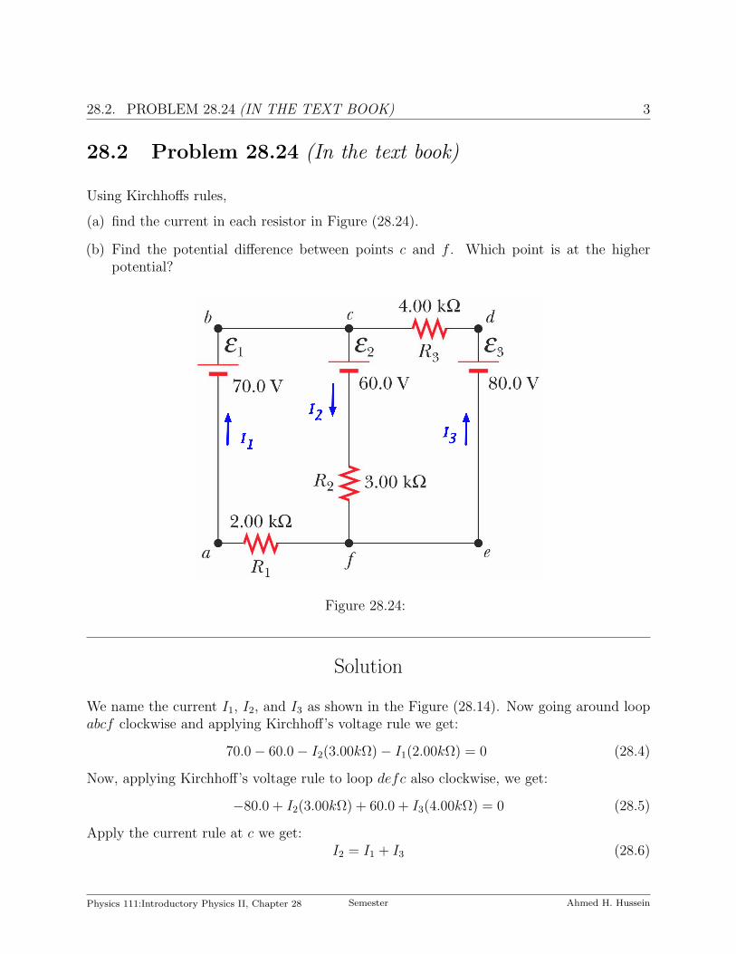
(a) find the current in each resistor in Figure (28.24).
(b) Find the potential difference between points c and f . Which point is at the higherpotential?
Figure 28.24:
Solution
We name the current I1, I2, and I3 as shown in the Figure (28.14). Now going around loopabcf clockwise and applying Kirchhoff’s voltage rule we get:
70.0− 60.0− I2(3.00kΩ)− I1(2.00kΩ) = 0 (28.4)
Now, applying Kirchhoff’s voltage rule to loop defc also clockwise, we get:
−80.0 + I2(3.00kΩ) + 60.0 + I3(4.00kΩ) = 0 (28.5)
Apply the current rule at c we get:I2 = I1 + I3 (28.6)
Physics 111:Introductory Physics II, Chapter 28 Semester Ahmed H. Hussein
4CHAPTER 28. DIRECT CURRENT CIRCUITS. SOLUTIONS OF HOME WORK
PROBLEMS
(a) Substituting for I2 from Equation (28.6) in Equation (28.4) ans solving the resultingthree equations we get:
I1 = 0.385 mA
I2 = 2.69 mA
I3 = 3.08 mA
(b) The potential difference between point c and point f staring from c to f is:
∆Vcf = Vc − Vf = 60.0 + I3(3.00 kΩ) = 60 + 3.08 mA× 3.00 kΩ = 69.2 V
Point c is at higher potential than f .
Physics 111:Introductory Physics II, Chapter 28 Semester Ahmed H. Hussein

28.3. PROBLEM 28.26 (IN THE TEXT BOOK) 5
28.3 Problem 28.26 (In the text book)
In the circuit of Figure (28.26), determine the current in each resistor and the voltage acrossthe 200-Ω resistor.
Figure 28.26:
Solution
We have four unknowns, so we need for equations. Naming the currents as shown in Figure(28.26), we find from applying the current rule at d and the voltage rule to loops abcd, dcfeand efgh clockwise we get:
w + x + z = y
−200w − 40.0 + 80.0x = 0
−80.0x + 40.0 + 360− 20.0y = 0
+20.0y − 360− 80.0 + 70.0z = 0
Physics 111:Introductory Physics II, Chapter 28 Semester Ahmed H. Hussein

6CHAPTER 28. DIRECT CURRENT CIRCUITS. SOLUTIONS OF HOME WORK
PROBLEMS
eliminating y by substitution we get
2.5w + 0.500 = x
400− 100x− 20.0w − 20.0z = 0
440− 20.0w − 20.0x− 90.0z = 0
Eliminating x we get:
350− 270w − 20.0z = 0
440− 70.0w − 90.0z = 0
Eliminating z we get:
z = 17.5− 13.5w and 430− 70.0w − 1575 + 1215w = 0
and w becomes:
w =1145
1145= 1.00 A
andz = 4.00 A
We can find x and y as:x = 3.00 A
andy = 8.00 A
The potential difference across the 200 Ω resistor is then:
∆V = IR = wR = 1.00 A× 200 Ω = 200 V
Physics 111:Introductory Physics II, Chapter 28 Semester Ahmed H. Hussein

28.4. PROBLEM 28.36 (IN THE TEXT BOOK) 7
28.4 Problem 28.36 (In the text book)
In the circuit of Figure (28.36), the switch S has been open for a long time. It is thensuddenly closed. Determine the time constant
(a) before the switch is closed and
(b) after the switch is closed.
(c) Let the switch be closed at t = 0. Determine the current in the switch as a function oftime.
Figure 28.36:
Solution
(a) While the switch is open, the battery charges the capacitor. The current used to chargethe battery is determined by the two resistors in series with the battery. So, the timeconstant τopen is:
τopen = RC = (50.0 kΩ + 100 kΩ)× 10µF = 1.5 s
(b) When the switch is closed, the capacitor discharges through 100 kΩ resistor, so the timeconstant τclosed is:
τclosed = 100 kΩ× 10 µF = 1.0 s
(c) The current through the closed switch will produced by the battery Ib and while thecapacitor is discharging a current Ic, the total current trough the switch is then:
I = Ib + Ic =∆Vb
R+ Ie
−t/τclosed =10
50.0× 10³+ Ie
−t/1.00 = 200 µA + Ie−t/1.00
Physics 111:Introductory Physics II, Chapter 28 Semester Ahmed H. Hussein

8CHAPTER 28. DIRECT CURRENT CIRCUITS. SOLUTIONS OF HOME WORK
PROBLEMS
To find I we notice that once the capacitor is fully charged, there will be no currentflowing in the circuit an no potential differences on the two resistors. This means thatpotential difference across the capacitor is the same as that across the battery i.e. 10V . Once the switch is closed the initial current due to the discharge of the capacitoris determined by the initial potential difference across the capacitor and the resistorthrough which the discharge takes place. So,
I =10.0 V
100 kΩ= 100 µA
and the total current becomes:
I = 200 + 100e−t/1.00 µA
A long time after the switch is closed the capacitor is fully discharged and the currentin the switch will be mainly from the battery.
Physics 111:Introductory Physics II, Chapter 28 Semester Ahmed H. Hussein

28.5. PROBLEM 28.42 (IN THE TEXT BOOK) 9
28.5 Problem 28.42 (In the text book)
A typical galvanometer, which requires a current of 1.50 mA for full-scale deflection and hasa resistance of 75.0 Ω, may be used to measure currents of much greater values. To enable anoperator to measure large currents without damage to the galvanometer, a relatively smallshunt resistor is wired in parallel with the galvanometer, as suggested in Figure (28.27).Most of the current then goes through the shunt resistor. Calculate the value of the shuntresistor that allows the galvanometer to be used to measure a current of 1.00 A at full-scaledeflection. (Suggestion: use Kirchhoffs rules.)
Figure 28.27:
Solution
Applying Kirchhoff’s loop rule we get:
−Ig × 75 Ω + (I − Ig)Rp = 0
Physics 111:Introductory Physics II, Chapter 28 Semester Ahmed H. Hussein

10CHAPTER 28. DIRECT CURRENT CIRCUITS. SOLUTIONS OF HOME WORK
PROBLEMS
The Galvanometer requires 1.5 mA for full deflection, to use it to give full deflection for 1A we then set Ig = 1.5 mA and I = 1 A in the above equation, and Rp becomes:
Rp =75× Ig
I − Ig
=75× 1.5× 10−3
1− 1.5× 10−3= 0.113 Ω
Physics 111:Introductory Physics II, Chapter 28 Semester Ahmed H. Hussein
28.6. PROBLEM 28.50 (IN THE TEXT BOOK) 11
28.6 Problem 28.50 (In the text book)
Aluminum wiring has sometimes been used instead of copper for economy. According tothe National Electrical Code, the maximum allowable current for 12-gauge copper wire withrubber insulation is 20 A. What should be the maximum allowable current in a 12-gaugealuminum wire if the power per unit length delivered to the resistance in the aluminum wireis the same as that delivered in the copper wire?
Solution
Since the power is the same in both wires, then:
I2AlRAl = I2
CuRCu or IAl =
√RCu
RAl
ICu =
√ρCu
ρAl
ICu =
√1.70
2.82× 20.0 = 15.5 A
Physics 111:Introductory Physics II, Chapter 28 Semester Ahmed H. Hussein

12CHAPTER 28. DIRECT CURRENT CIRCUITS. SOLUTIONS OF HOME WORK
PROBLEMS
28.7 Problem 28.68 (In the text book)
Switch S has been closed for a long time, and the electric circuit shown in Figure (28.68)carries a constant current. Take C1 = 3.00 µF , C2 = 6.00 µF , R1 = 4.00 kΩ, and R2 = 7.00kΩ. The power delivered to R2 is 2.40 W .
(a) Find the charge on C1.
(b) Now the switch is opened. After many milliseconds, by how much has the charge on C2
changed?
Figure 28.68:
Solution
(a) With the switch closed, current exists in the circuit as shown in the top part of Figure(28.68). The capacitors carry no current. For R2 we have
P = I2R2 then I =
√P
R2
=
√2.40
7000= 18.5 mA
The potential difference across R1 and C1 is
∆V1 = IR1 = 1.85× 10−2 × 4000 = 74.1 V
Physics 111:Introductory Physics II, Chapter 28 Semester Ahmed H. Hussein

28.7. PROBLEM 28.68 (IN THE TEXT BOOK) 13
Figure 28.69:
The charge on C1 is
Q = C1∆V = 3.00× 10−6 × 74.1 = 222 µC
The potential difference across R2 and C2 is:
∆V2 = IR2 = 1.85× 10−2 × 7000 = 130 V
The charge on C2 is:
Q = C2∆V = 6.00× 10−6 × 130 = 778 µC
The battery emf is:
∆V = ∆V1 + ∆V2 = 74.1 + 130 = 204 V
or∆V = IReq = I(R1 + R2) = 1.85× 10−2 × (4000 + 7000) = 204 V
(b) In equilibrium after the switch has been opened, no current exists. The potential dif-ference across each resistor is zero. The full 204 V appears across both capacitors. Thenew charge C2 is:
Q = C2∆V = 6.00× 10−6 × 204 = 1222 µF
and the change is 1222− 778 = 444 µF
Physics 111:Introductory Physics II, Chapter 28 Semester Ahmed H. Hussein