chapter 2 literature review - information and...
TRANSCRIPT

12
CHAPTER 2
LITERATURE REVIEW
2.1 GENERAL
For understanding the seismic behavior of precast concrete
structures, the study of behavior of joints is of great importance as the
connections form the weakest link in the structure. Experimental studies are
necessary as it gives the realistic response of the structure. But Finite Element
Modeling as gained importance as experimental investigations though
accurate can be time consuming and costly. The use of Finite Element
packages to model the structural elements is faster and cost effective. Hence,
many parameters can be studied by modeling the structural elements using
Finite Element packages. Several researchers worldwide have investigated the
behaviour of precast beam-column connections under earthquake loading both
experimentally and analytically. A detailed review of the literature has been
carried out to understand the behaviour of precast beam column connections
under cyclic loading. Among these the most significant literatures are briefly
summarized in this chapter. The finite element modeling related to precast
beam-column modeling related work are also reviewed.

13
2.2 OVERVIEW OF LITERATURE
2.2.1 Studies on Experimental Investigations of Precast Beam
Column joints under Seismic Loading
2.2.1.1 Wet Connections
Bull and Park (1986) investigated the performance of cast-in-place
reinforced concrete moment resisting frames incorporating precast prestressed
concrete U- beam shells subjected to seismic loading. The precast beams
acted as permanent formwork and were not connected by steel to the
cast-in-place concrete of the beam or column. Three full scale exterior beam
column subassemblies were tested. It was concluded that the two specimens
that were designed for seismic loading was satisfactory and can be used in
ductile seismic resisting frame. The third specimen that was designed without
special provisions for seismic loading was suitable for non seismic resisting
frames where the seismic loads are carried by walls and other structural
systems.
Cheok and Lew (1991) attempted to develop moment resisting
precast concrete connections in seismically active regions by testing four one-
third scale monolithic concrete beam-to-column connections. Two were
designed according to the 1985 Uniform Building Code (UBC) Seismic zone
2 criteria and two according to UBC zone 4 criteria. In addition, two precast
post-tensioned concrete beam-to-column connection similar in design to the
monolithic zone 4 specimens were tested. It was concluded that post-
tensioned precast concrete beam-column connections are strong and as ductile
as the monolithic connections, for high seismic regions. However, the per
cycle and cumulative energy dissipation characteristics, of the precast beam-
column connections could be improved.
14
Cheok and Lew (1993) tested eight 1/3-scale model precast beam to
column interior connections under cyclic loading. In general, the precast
concrete specimens had higher storey drifts at failure and higher initial
stiffness than monolithic specimens. The measured maximum concrete
strengths exceeded the calculated values and performed as well as monolithic
specimens in most cases. The cumulative energy dissipated to failure by
precast specimens was greater than that of monolithic specimens.
Castro et al (1994) investigated the seismic performance of a newly
developed precast system with the concrete members at the ends and the bar
connections are located at the middle of the precast members where the
stresses are small. Tests were conducted on nine two-thirds scale interior
beam-column joints including a monolithic specimen. The behaviour with
respect to bending strength of the beams, the shear strength and bond
deterioration at the beam column joint core and energy dissipation were
studied. It was concluded that precast concrete specimens can sustain
inelastic deformations under cyclic loading and can be ductile as cast-in-situ
specimens.
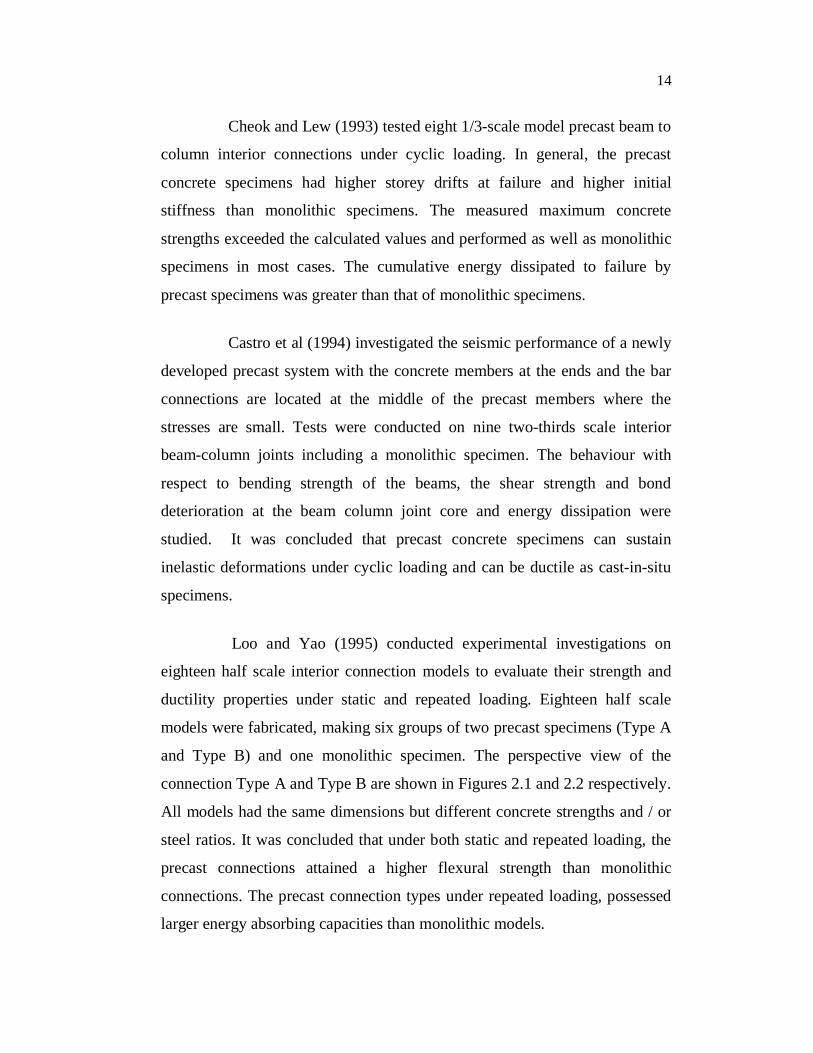
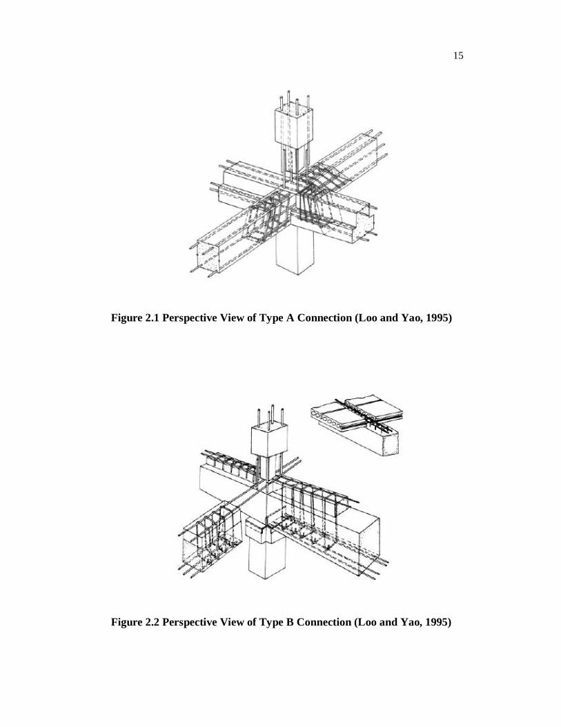
Loo and Yao (1995) conducted experimental investigations on
eighteen half scale interior connection models to evaluate their strength and
ductility properties under static and repeated loading. Eighteen half scale
models were fabricated, making six groups of two precast specimens (Type A
and Type B) and one monolithic specimen. The perspective view of the
connection Type A and Type B are shown in Figures 2.1 and 2.2 respectively.
All models had the same dimensions but different concrete strengths and / or
steel ratios. It was concluded that under both static and repeated loading, the
precast connections attained a higher flexural strength than monolithic
connections. The precast connection types under repeated loading, possessed
larger energy absorbing capacities than monolithic models.
15
Figure 2.1 Perspective View of Type A Connection (Loo and Yao, 1995)
Figure 2.2 Perspective View of Type B Connection (Loo and Yao, 1995)

16
Stone et al (1995) developed a hybrid precast system, which was
designed to have the same flexural strength as a conventionally reinforced
system with the same beam size. The hybrid system was self-centering and
displayed essentially no residual drift. The hybrid system had a very large
drift capacity. The hybrid system dissipated more energy per cycle than the
conventional system for upto 1.5 percent drift. The concrete in the hybrid
suffered negligible damage, even at drifts up to 6 percent.
Restrepo et al (1995) conducted tests on six assemblages of
perimeter frames under quasi static cyclic reversed loading. Four units were
connected at the beam midspan and two units were connected at the beam-to-
column joint region. Units 1, 2 and 3 had connections between precast
concrete elements at mid span of beams consisting of overlapping hooks or
straight splices in cast-in-situ concrete showed excellent performance under
cyclic loading. Unit 4 had strong regions at the ends of the precast beams and
a diagonally reinforced cast-in-place connection region at the beam midspan,
with diagonal bars connected by bolted steel plates welded to the bars. The
test of this unit showed limited ductility response due to the bursting forces
that had not been considered in the initial design. It showed full ductility after
the damaged region was repaired by adding transverse reinforcement and
bearing rods at the bend of the diagonal reinforcement. Unit 5 had the precast
concrete placed between the columns and a cast-in-place concrete joint core
between the ends. Unit 6 had precast concrete beam element passing the
column and the longitudinal column bars grouted in vertical corrugated ducts
in beam-to-column joint region. Both Unit 4 and 5 showed excellent
performance in terms of strength and ductility.
Preistly and MacRae (1996) tested two ungrouted post-tensioned
precast concrete beam to column sub-assemblages under cyclic reversals of
inelastic displacements. One sub-assemblage represented an exterior joint

17
while the other was an interior joint of a one-way prestressed concrete frame.
The test specimens were designed with gradually reduced beam and joint
shear reinforcement compared with equivalent monolithic joints, but with
special spiral confinement of the beam plastic hinge regions. Both
subassemblages performed well, with only minor damage upto drift ratios of 3
percent. It was concluded that satisfactory seismic performance can be
expected from well designed ungrouted precast, post-tensioned concrete
frames.
Stanton et al (1997) studied a precast framing system with precast
elements connected by unbounded post –tensioning steel and bonded
reinforcing bars. The behavior was compared with a pair of conventional
monolithic; cast-in-place frames. It was concluded that a hybrid system can be
designed to have the same flexural strength as a conventionally reinforced
system with members of the same size. The shear resistance of the hybrid
system was superior to that of a conventionally reinforced frame. The hybrid
system was self centering and displayed no residual drift and had very large
drift capacity. It dissipated more energy per cycle than conventionally
reinforced frame up to a drift of 1.5 percent. It was also observed that damage
in the hybrid system was minimal.
Elliot et al (1998) studied the behavior of structural beam to column
connections in precast concrete skeletal and portal structures. The types of
connections adopted for beam to column testing is shown in Figure 2.3. In
most of the connections, ductile modes of failure were observed. The authors
concluded that the frame stability can be enhanced by utilizing the strength
and stiffness of precast concrete beam to column connections in a semi rigid
frame analysis. This method was found for internal connections but not for
edge connections.

18
Figure 2.3 Types of Connections Used in Precast Beam to Column
Tests (a) Billet (b) Welded Plate ( Elliot et al, 1998)
Vasconez et al (1998) developed a high energy absorbing joint for
precast concrete structures in seismic zones. The material of the joint was a
High Performance Fibre Reinforced Cement Composite (HPFRC) matrix. The
FRC based connection design was successful in making the connection act as
a plastic hinge by spreading the yielding from centre to the interfaces. The
steel fibres used in cast-in-place connection lead to an increase in strength,
energy capacity, stiffness, displacement and rotation capacities. There was a
decrease in damage and shear deformations. Steel fibres were found to be
more effective in improving the response of the joint than polyvinyl alcohol
fibres. It was also observed that reducing the confinement provision of the
ACI by 50 percent in steel fibre reinforced connections resulted in improved
behaviour compared to normal RC specimens with full confinement.
19
Alcocer et al (2002) conducted experiments on two full scale beam-
column precast concrete joints under uni-directional and bi-directional
loading that simulated earthquake type loadings. The most relevant feature of
the connection is that conventional mild steel reinforcing bars or prestressing
strands, rather than welding or special bolts, were used to achieve beam
continuity. Specimen design followed the strong-column–weak-beam
concept. Beam reinforcement was purposely designed and detailed to develop
hinges at the joint faces and to impose large inelastic shear force demands
into the joint. As expected, the joint controlled the specimen failure. In
general, the performance of both beams-to-column connections was
satisfactory. Joint strength was 80 percent of that expected for monolithic
reinforced concrete construction. Specimen behavior was ductile due to hoop
yielding and bar pullout, while strength was nearly constant up to drifts of 3.5
percent.
Khaloo and Parastesh (2003) studied four types 2/5 scale model
precast connection and one monolithic concrete beam-column connections. In
the precast specimen, the load was transferred in the spliced reinforcement by
a combination of lap splicing and end anchorage of bars. The end portions of
the beams were designed in the form of a channel that sat on the column
bearing area and carried the shear stresses due to the slab. Then the
connection length region is grouted to form the monolithic connection. The
main variables of this study were the level of axial load of the column,
spacing of beam stirrup in the connection length region, gravity load on the
beam and use of steel fibre in grout of the connection region. The authors
concluded that all the specimens were capable of providing strength, ductility,
and storey drift and energy dissipation comparable with that of reference
specimen. A reduction in the axial load, the use of steel fibre region in grout
of the connection length region significantly increased the ductility, storey
drift, strength and energy absorption of the precast connection. The presence

20
of concentrated gravity loads on beams increased the strength, ductility and
storey drift as compared with reference specimen.
Khaloo and Parastesh (2003) carried out an experimental study to
investigate a simple moment-resisting precast concrete beam-column
connection under cyclic inelastic loading. Four precast beam-column
connections and one monolithic connection were tested. The variables
examined were the connection length of reinforcements and presence of
transverse bars at mid height of connection. It was concluded that the
reduction in connection length reduced strength, ductility and energy
absorption. The failure mode changed toward partial separation and slippage
of bond between the precast concrete beam and the cast-in-place grout. The
presence of transverse bars in the connection length enhanced the seismic
behavior of the precast connection system.
Blandon and Rodriguez (2005) conducted experimental study of a
half-scale two storey precast concrete structure built with a dual structural
system (combination of structural walls and frames). A typical feature in
some of the beam to column connections in the test structure was that the
beam bottom longitudinal bars in the joint region were poorly anchored. The
test structure was subjected to simulated seismic loading until the structure
reached failure. The responses of the precast structural elements and their
connections during testing, including beam to column connections, column to
foundation connections and the diaphragms were observed. A pull-out was
observed in the beam bottom bars. Due to this failure pattern, the use of dual
structural systems is a promising solution for the construction of seismic
resisting precast concrete building. In a dual system, the deformation demands
in the beam to column connections of the frame subsystem can be
significantly reduced when compared with the case the case of a building built

21
with frames only system for resisting lateral loads. As a result, the frame
system could be designed for limited ductility.
Joshi et al (2005) performed experiments on two precast and an
equivalent monolithic exterior beam-column joint sub-assemblage specimen.
The schemes for the anchorage of beam bars were different in the two set of
specimens. In the first type of detailing, a single U-bar is used as top and
bottom beam reinforcements as shown in Figure 2.4. The other type of
detailing conforms to the Indian Standard Code for ductile detailing of
reinforced concrete sections as shown in Figure 2.5. In precast specimens, the
connectivity of reinforcement bars between beam and column was achieved
by welding the exposed bars of the components in the point region. Under
displacement–controlled pseudo-static loading, the monolithic specimen with
beam bars anchored into the column performed better than the monolithic
specimen with continuous U-bars as beam reinforcement. The cumulative
energy dissipation for the monolithic specimen with continuous U-bar
reinforcement was more than the other monolithic specimen. The precast
specimens with beam bars anchored into the column performed better than the
corresponding monolithic beam. The precast specimen with continuous U-
bars as beam reinforcement performed worse than the corresponding
monolithic specimen, due to high average strength and stiffness deterioration.
Of the two precast specimens, the one with the beam bars anchored into the
column with the welding of the lap splices performed better than the one with
continuous U-bars as beam reinforcement.

22
Figure 2.4 Details of the Reinforcement of the First Specimen
(Joshi et al 2005)
Figure 2.5 Details of the Reinforcement of the Second Specimen (Joshi
et al 2005)
Korkmaz and Tankut (2005) investigated the seismic behaviour of
the connection detail proposed by an industrial partner and the specimens
with improved details, in order to develop a moment resisting precast concrete
beam to beam connection. In this study, six beam–beam connection

23
subassemblies were tested under reversed cyclic loading simulating severe
earthquake action. The first specimen was a monolithic specimen used as a
reference specimen and tested to define the reference behaviour. The second
specimen was a precast specimen, which was detailed by a company
specializing in precast concrete production. The remaining specimens were
modified according to the results of the formerly tested specimens. All of the
specimens were identical in dimensions. All test specimens were 1/2.5 scaled
models of the improved connection details used in the highly critical
earthquake zones. The behavior of the precast members was compared with
that of the reference one and with the others. Though the original connection
did not perform well, the modified precast connection showed satisfactory
performance and was recommended for use in seismic zones.
Rodriguez and Blandon (2005) tested a half-scale two-storey
precast concrete building incorporating a dual system representing a parking
structure in Mexico City under simulated cyclic loading. The observed global
response showed that showed the importance of the reinforced concrete wall
participation in the response. This participation led to an important reduction
in the deformation demands in the critical section of the precast frame
members. The displacement ductility demand was found to be higher in the
wall sub-system than in the frame sub-system of the dual system. Some of the
beam to column details that had substandard reinforcing details had poor
deformation capacity. But the observed and calculated deformation demands
in these connections were not critical since they were significantly reduced by
the wall interaction.
Khoo et al (2006) tested two full scale precast concrete sub-frames
in which the connection are constructed on the beam span and kept away from
the column faces so as to avoid coinciding with the plastic hinge regions
during seismic excitations. The variable examined was the connection detail.

24
One connection was composed of overlapping 90° hooks. All the beams
longitudinal bars were spliced using such hooks and the overlaps started at
about ‘1.8d’ from the column face where‘d’ is the effective beam depth. Two
sets of stirrups spaced at 120mm were installed at the overlapping hooks. The
other connection consisted of overlapping 180° hooks starting at ‘1.75 d’ from
the column face. The stirrups were similar to that of the first connection. It
was concluded that the precast concrete frames were capable of matching the
overall performance of the monolithic connections and thereby providing
moment resisting behavior.
Chun et al (2007) assessed the effectiveness of headed bars
terminating in exterior beam-column joints. Nine inter storey and five roof-
level joint specimens were tested under reversed cyclic loading. The primary
test parameters were the anchorage type, size and arrangement of the beam
bars and the heads and the detailing provided for roof joints. The test results
indicated that hysteretic behaviour of exterior joints constructed with headed
bars was similar or superior to joints constructed and tested with hooked bars.
Head size with a net area of three to four times the bar area was sufficient to
anchor the beam reinforcement effectively within the exterior beam column
joint. It was also concluded that in addition to providing vertical U-bars at
roof joints, heads on column bars should extend beyond the beam top bars to
provide improved behavior.
Nishiyama and Wei (2007) conducted cyclic load tests on seven
precast, prestressed concrete beam to column joint assemblages. The
experimental parameters studied were location of tendon anchorage,
prestressing steel content in the beam section, concrete compressive strength
and to investigate the shear strength of the beam to column joint. It was
concluded that maximum load capacities for test units with inside anchorages
were 9% to 13% less than specimens with anchorage outside the joint core.

25
Joint shear deformation was less in the test units with outside anchorage than
in test units with inside anchorage. Damage to the beam to column joint
assemblages and the decay of the maximum capacities of the test units were
due not only to joint shear failure but also to anchorage deterioration of the
prestressing steel.
Xue and Yang (2010) studied the behavior of precast concrete
connections in a moment resisting frame under cyclic loading. The
connections studied were exterior connection, interior connection, T
connection and knee connection. It was observed that Knee connections were
less effective when compared to other connections. All the connections
exhibited strong column-weak beam failure mechanism. It was concluded that
all the connections performed satisfactorily in seismic conditions with respect
to strength, ductility and energy dissipation capacity.
2.2.1.2 Dry Connections
Dolan and Pessiki (1984) demonstrated that the behaviour
characteristics of a welded monotonically loaded precast concrete connection
can be simulated using models. Tests of one-quarter scale models of a single
beam to column connection were conducted. Good agreement was found
between the strength and the normalized moment rotation response of the
model and the prototype. The effects of weld quality and design eccentricities
had similar consequences in both model and prototype.
Ochs and Ehsani (1993) tested five precast beam to column
subassemblies under simulated earthquake type loading. The columns
included steel plates or angles embedded in the columns and beams which
facilitated field erection. Various connection details were studied. One
connection was a monolithic specimen and four were precast specimens.
Specimen P1 and PR1 consisted of two fabricated T-sections embedded in the

26
column. Each T-section had three holes to allow for the passing of the column
longitudinal bars. Four No.7 standard 90 degree hooks were welded to the T-
sections to provide adequate anchorage of the plate within the joint. The beam
end included two large single angles to which longitudinal reinforcement was
welded. The beam angles were welded to column section with fillet welds
over full width of the beam. Specimen PR1 differed from P1, as additional
intermediate reinforcement in the form of U-shaped No.6 bars was used. For
specimens P2 and PR2 the connection was similar to that of specimen P1 and
PR1. The only change made was that on the lower side a straight plate which
extended from the column face was utilized instead of a T-section. It was
concluded that precast concrete specimens performed similarly to that of
monolithically cast concrete connection. The precast column was strong
enough to force a plastic hinge away from the column face. The critical part
of the precast connections was the welded beam bars as they initiated the
failure of specimens. It was also observed that the intermediate reinforcing
bars in the precast concrete specimens had less effect on the capacity of the
specimen early in the test, however as the test progressed, these bars
contributed to the specimen capacity.
Ersoy and Tankut (1993) tested precast concrete beams with dry
joints designed for multistory buildings located in a seismic area under
reversed cyclic loading. The original beam consisted of two steel plates one at
top, the other at the bottom, welded to the anchored steel plates in the column
bracket and the beam. The design was later revised by adding side plates. The
main variables were presence of side plates and joint width. The authors
concluded that the joint width is an important parameter and therefore
tolerances should be checked carefully during erection. The strength, stiffness
and energy dissipation of the member with side plates were comparable to
those of monolithic member.

27
Englekirk (1995) developed an energy absorbing ductile connector
that can be to construct a seismic moment resisting frame of precast concrete
components. The ductile connector was a ductile rod which was the yielding
element. The function of the ductile rod was to accommodate post yield
system deformations. Two types of ductile rods were used (i) milled and (ii)
cast. It was suggested that the rod bearing transfer mechanism could be
improved by increasing the bearing area and adding a confining plate at the
face of the column. It was observed that the strain hardening characteristics of
the material used in the casting were better than that used in milled rod.
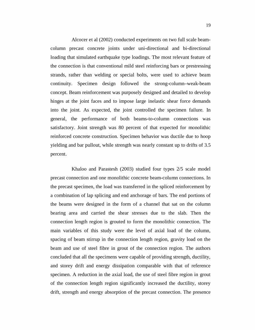
Priestley et al (1999) tested a large-scale five-storey precast
concrete building constructed to 60 percent scale under simulated seismic
loading. It was concluded that behaviour of the structure was extremely
satisfactory, with only minimal damage in the shear wall direction, and no
significant strength loss in the frame direction, though it was tested to drift
levels upto 4.5 %, more than 100 percent higher than the design drift level.
The different precast connections adopted are shown in Figure 2.6(a) to (d).
Spieth et al (2004) presented the results of an experimental study
together with companion of analytical modeling of two distinctly different
precast concrete beam to column connections. The first consists of precast
concrete beams with armored end connections connected directly to the
column, while the second is a connection offset away from the column at
about the 1/8 point within the span. In both cases, the beams were connected
via un-bonded post-tensioned high strength prestressing thread bars to a
prestressed concrete column. Lateral loading tests were conducted up to ±4%
drift with and without supplementary mechanical energy dissipators. The
results show that the non-linear moment-rotation performance can be
accurately modeled. From this study it was concluded, that with appropriate
28
armouring of the precast members, damage can be avoided to the connection,
while the entire structure is self-centered following an earthquake.
a) Hybrid Post Tensioned Connection
b) Pretensioned Connection
Figure 2.6 Different Precast Connections Adopted (Priestley et al 1999)

29
c) TCY-Gap Connection
d) TCY Connection
Figure 2.6 (Continued)
30
Ousalem et al (2009) studied the seismic performance of an
assembled precast high strength concrete beam with a simple and innovative
lap splice connection in high rise buildings. The flexibility variation along the
lap splice connection of the beam, which involves a reduced profile, was also
investigated. The lap splice connection, located at beam mid span was
connected by transverse bolts. The authors concluded that the beams under
reversed cyclic loading proved to be ductile and failure occurred outside the
lap splice connection similar to monolithic ordinary reinforced concrete
beams. The flexural stiffness varied along the lap splice connection of the
assembled beam and declined at the transition section of the reduced profile
under large loading. The reduction in the effective flexural stiffness at the
location of the transition section did not jeopardize the performance of the
assembled precast beam within the design limits.
Ousalem et al (2009) investigated the seismic performance of two
precast high strength reinforced concrete exterior beam-column joints
subjected to varying high axial levels. High grade steel bars were used as
reinforcement. Splice grout-sleeves and mechanical anchors were used in
columns and beams respectively. The maximum axial tension level in the
columns was 90% of the yield strength of the main bars. It was concluded that
the tested specimens under high axial tension loads performed well and
showed stable response with the lateral storey drift angle of 3%, exhibited
appropriate response characteristics, lateral force resistance and energy
absorption capacity. The bond deterioration of the beam main bars in joints
subjected to varying axial load was higher under axial tension load than under
axial compression load. The mechanical anchors were very effective and no
sign of concrete crushing was observed within lateral storey drift of 2%.
Kaplan et al (2009) tested a typical pin connected precast concrete
frames strengthened with external shear walls under reversed cyclic imposed

31
drift at a constant rate. The experiments showed that the structure with shear
walls showed increased lateral stiffness and lateral load resisting capacity and
provided an effective diaphragm for the structure.
2.2.1.3 Hybrid Connections
Dolan et al (1987) tested a two bay by two storey moment resisting
frame which included several moment resisting connections. The various
types of connections adopted were (i) beam to column connection using
welded plates for the positive and negative connections (ii) beam to column
connections using continuous reinforcing through the column and cast-in-
place topping and positive moment connection using welded plates (iii)
connection using bolts (iv) a precast beam constructed into a cast-in-place
column (v) a precast beam post-tensioned to a column (vi) a precast beam
installed on a grouted dowel (vii) a precast beam made continuous using
DYWIDAG threaded bars screwed into couplers cast in the column. It was
concluded that all the connections developed strengths and were considered
strong enough for their intended use. The bolted connection was found to
exhibit energy dissipation similar to monolithic connections.
Ertas et al (2006) presented the test results of four types of ductile,
moment-resisting precast concrete frame connections and one monolithic
concrete connection, all designed for use in high seismic zones. The
performances of the precast concrete connections subject to displacement
controlled reversed cyclic loading were compared with that of the monolithic
connection. The precast concrete connections tested were subdivided into
three groups namely cast-in-place, composite with welding, and bolted. The
cast-in-place connections were located in either the beam or the column of the
precast concrete subassemblies. The composite connection is a common detail
used in the Turkish precast concrete industry. Two bolted specimens without
corbels were also tested. Through these tests, the responses of different
32
connection types under the same loading pattern and test configuration were
compared. Comparisons of performance parameters, such as energy
dissipation and ease of fabrication, revealed that the modified bolted
connections may be suitable for use in high seismic zones.
Ozden and Ertas (2007) presented the test results on post-tensioned,
precast concrete moment-resisting, beam-column connections containing
different mild steel reinforcement contents. In the experimental program, five
hybrid connections were tested under displacement controlled reversed cyclic
loading. Each hybrid connection was compared with the test result of the
reference monolithic subassembly in terms of connection strength, stiffness
degradation, energy dissipation, and permanent displacement. The response of
post tensioned, precast concrete hybrid connections approached that of the
monolithic subassembly as the mild steel reinforcement content increased.
Connection capacities were well predicted by the joint gap opening approach.
The design assumptions of hybrid connections are best satisfied with a 30%
mild steel reinforcement contribution to the connection’s flexural capacity.
Kulkarni and Li (2009) conducted experimental and finite element
method investigation of hybrid steel-concrete beam-column joints subjected
to seismic loading. Four prototype specimens of beam-column joints with
slabs were tested under reversed cyclic loading. Two were cast-in-place
concrete specimens, and two were precast concrete specimens constructed
with hybrid connections. The rectangular column simulated two different
structural combinations, one was strong column-weak beam and another was
weak columns-strong beam. Both were tested to evaluate how the connection
details of the different systems influenced the strength of the joints. It was
observed that the precast concrete achieve consistent hysteretic loops
throughout the cyclic loading and behaved well compared with cast-in-place
connections. The top reinforcement of precast concrete specimens was
stressed to a higher level than cast-in-place concrete top reinforcement during

33
seismic loading, but a lower state of stress level can be achieved in precast
concrete construction with an increase in plate thickness of the hybrid
connection. The hybrid connection with a strong column-weak beam system,
an axial load between zero and 0.2fc´ Ag enhances performance. For the
connections with a weak column-strong beam system, the axial load ranging
from zero to 0.1 fc´Ag, where fc´ and Ag are cylinder compressive strength and
gross area of column respectively. The increase in plate thickness, the hybrid
connection was capable of carrying the required storey shears and the energy
dissipation of the joint increases. The Finite Element analysis and
experimental results were found to be good agreement.
Li et al (2009) conducted experimental and analytical investigations
of hybrid-steel concrete connections. Four full scale specimens, included one
cast-in-place and three precast specimen were tested under cyclic load
reversals. The critical parameters influencing the joint’s behavior such as
continuation of beam bottom reinforcement, column axial load, the size and
embedded length of the angle sections are varied and their effects including
possible implications on code specifications are discussed. Experimental
observations showed that precast specimens under cyclic loading experienced
no abrupt damage within the joint core region and therefore, the final failure
was not controlled by the capacity of the joint core. The precast specimen’s
performance was good at exhibiting adequate ductile behavior under seismic
loading and it also agreed well with cast-in-place specimen. Embedment of
the steel sections in the joint greatly enhanced the strength of the joint core
with the specimens carrying storey shears up to a ductility factor of 3.5. Beam
to column connection of precast specimens was sufficiently stiff and ductile
and effectively resisted both shear forces and bending moments. Joint core
regions of the precast specimens were adequately confined by the
incorporated steel sections, providing significantly high degree of restraint

34
and reducing the joint core deformation under reversed cyclic loading. The
Finite Element analysis results compared well with the experimental results.
Thinh et al (2009) tested a new type of precast unbounded post-
tensioned exterior beam-column joint of a long span frame under the
simultaneous action of gravity load and cyclic load. Four specimens were
tested. The first specimen was designed with shear bracket that resisted the
shear force induced by designed gravity load. The second specimen was
designed without shear bracket. The third specimen was designed with shear
bracket to resist shear force induced by gravity load which is 1.5 times of that
of the first specimen. The fourth specimen was designed similar to the first
specimen, but had the slab and spandrel beam. It was concluded that specimen
with shear bracket exhibited good hysteretic behavior with small residual
deformation. Specimen without shear bracket experienced large beam slip.
Excessive crushing of the slab together with fracture of slab reinforcement
caused deterioration of strength with large residual deformation. It was
proposed that the design of shear bracket and inverted U-shaped steel box
should be modified to prevent the deformation of these parts under the action
of very large gravity load and cyclic load.
2.2.2 Studies on Analytical Investigations of Precast Elements
2.2.2.1 Beam Elements
Faherty (1972) studied a simply supported reinforced and
prestressed concrete beam loaded with two symmetrically placed concentrated
transverse loads using the finite element method of analysis. The nonlinear
analysis considered the concrete nonlinear properties, the linear bond slip
relation with a destruction of the bond between the steel and concrete, and
bilinear steel properties. The transverse loading was incrementally applied
whereas the dead load, release of the prestressing force, the elastic prestress

35
loss, the time dependent prestress loss, and the loss of tensile stress in the
concrete as a result of concrete rupture were applied as single loading
increments. The results for the reinforced and prestressed beam showed that
deflections computed using the finite element model compared well with the
experimental results.
Barbosa and Ribeiro (1998) analysed a simply supported reinforced
concrete beam subjected to uniformly distributed load using finite element
package ANSYS. Due to transversal and longitudinal symmetry, a quarter of
the beam was modeled. Reinforcement was modeled as discrete reinforcement
and smeared reinforcement. Each type had been analyzed four times with four
different material models. Linear elastic behavior for both concrete and steel
was adopted for the first model, the former capable of cracking in tension and
crushing in compression. In the second model, crushing of compressed
concrete was disabled and an elastic perfectly plastic model based on
Drucker-Prager yield criterion had been used instead. A multilinear uniaxial
stress-strain relation, simulating a parabolic curve represented concrete
compressive behavior in the third model. Finally, crushing had been
associated to the multilinear stress-strain curve in order to compose the fourth
compression model for concrete. It was concluded that satisfactory prediction
of the response of reinforced concrete structures were obtained for all the
models.
Fanning (2001) conducted nonlinear analysis of reinforced and
post-tensioned concrete T-beams using finite element package ANSYS.
Quarter and half models were modeled for reinforced and post-tensioned
concrete T-beams respectively. SOLID65 element and LINK8 element were
used to model concrete and internal reinforcement. Discrete reinforcement
was favoured over the alternative smeared stiffness capability as it allowed
the reinforcement to be precisely located whilst remaining a relatively coarse

36
mesh for the surrounding concrete medium. For formulating the model for
post-tensioned beam LINK8 element was used for the post-tensioning cables,
with the remaining internal reinforcing bar modeled using distributed smeared
stiffness approach. The numerical model predicted well the nonlinear load-
deflection response of the beams upto failure. The finite element model
predicted the crack pattern similar to the test beam. It was concluded that for
capturing the flexural modes of failure of reinforced concrete systems, the
smeared crack model was an approximate numerical model.
Kachlakev et al (2001) studied the behavior of four concrete beam
members with externally bonded Carbon Fiber Reinforced Polymer (CFRP)
fabric using ANSYS. SOLID65 element, LINK8 element, SOLID46 element
and SOLID45 element were used to model concrete, steel reinforcement, FRP
composites and steel plates respectively. Symmetry allowed one quarter of
the beam to be modeled. It was concluded that in the load strain plots, the
strain in the linear stage from the FE analysis correlated well with those from
the experimental data. The yield load of steel from FE analysis was 14%
lower than that of the test results. In the linear range, the load deflection plot
was stiffer when compared to the experimental results. The first cracking
loads obtained form ANSYS was higher than the test data. ANSYS
underestimated the ultimate load of the beams by 5% to 24%.
Hu et al (2004) conducted numerical analysis using ABAQUS
finite element program to predict the ultimate load carrying capacity of
rectangular reinforced concrete beams strengthened by fibre reinforced
plastics applied at the bottom or on both sides of the beams. The steel
reinforcing bars, plain concrete and fibre reinforced plastics was simulated
using appropriate constitutive models. The influences of fibre orientation,
beam length and reinforcement ratios on the ultimate strength of the beams
were investigated. The behaviors of the beams with high and low

37
reinforcement ratios and strengthened with FRP at the bottom are not
influenced by the length of the beam significantly. The beams with high
reinforcement ratios and strengthened with FRP at the bottom had more
cracks at the central region than those with low reinforcement ratios. With
the same FRP layers, the ultimate strengths and the numbers of cracks of the
beams strengthened by FRP on both sides were much less than those
strengthened by FRP at the bottom.
Santhakumar et al (2004) conducted numerical study to simulate
the behavior of retrofitted reinforced concrete shear beams. The study was
carried out on the unretrofitted RC beam designated as control beam and RC
retrofitted using carbon fibre reinforced plastic (CFRP) composites with ±45º
and 90º fibre orientation. The finite elements adopted by ANSYS were used
for this study. A quarter of the full beam was modeled by taking advantage of
the symmetry of the beam and loadings. When compared with the
experimental models showed 8% increase in the ultimate load for control
beam and uncracked retrofitted beam and 8% decrease in the ultimate load for
precracked retrofitted beam. At the ultimate stage all the numerical models
show less deflection especially the precracked retrofitted beam showed 31%
less deflection.
Wolanski (2004) studied the flexural behavior of reinforced and
prestressed concrete beams using finite element analysis ANSYS. SOLID65
element and LINK8 were used to model the concrete and whereas SOLID45
was used to simulate the steel plate for loading area and supports. The
SOLID65 element required both linear isotropic and multilinear isotropic
material properties to properly model concrete. The multilinear isotropic
material used the Von Mises failure criteria along with William Warnke
model to define the failure of concrete. Deflections and stresses at the
centerline along with initial and progressive cracking of the finite element

38
model compared well with the experimental data. The failure mechanism of
the reinforced and prestressed concrete beam was modeled well and the
failure load was close to the experimental results.
Ibrahim and Mubarak (2009) studied the behavior of externally
prestressed continuous concrete beams subjected to symmetrical static
loading. A numerical model based on the finite element method using
ANSYS. The elements SOLID65 and LINK8 were used to model concrete
and steel reinforcement. The prestress in the finite element was given as an
initial strain in the link element. SOLID45 element was used for steel plates at
the support and loading location to avoid stress concentration problems. The
anchorage zone was modeled as steel plate which was connected to the tendon
element. The finite element analysis showed good agreement with the
experimental results throughout the entire range of behavior and failure mode.
Ibrahim and Mahmood (2009) presented an analysis model for
reinforced concrete beams externally reinforced with fibre reinforced polymer
(FRP) laminates using finite elements method adopted by ANSYS. The finite
element models are developed using a smeared cracking approach for
concrete and three dimensional layered elements for the FRP composites. The
results obtained from the ANSYS finite element analysis were compared with
the experimental data. The comparisons were made for load-deflection curves
at mid-span; and failure load. The results from finite element analysis were
calculated at the same location as the experimental test of the beams. The
accuracy of the finite element models is assessed by comparison with the
experimental results, which are to be in good agreement. The load-deflection
curves from the finite element analysis agree well with the experimental
results in the linear range, but the finite elements results are slightly stiffer
than that from the experimental results. The failure load obtained from the
numerical solution for all beams is slightly smaller than experimental load.

39
The maximum difference in ultimate loads for all cases is 7.8%. The final
loads for the finite element models are the last applied load step before the
solution diverges due to numerous cracks and large deflections.
Chansawat et al (2009) developed three-dimensional finite element
model to simulate the behavior of full scale reinforced concrete beams
strengthened with glass and carbon fibre reinforced polymer sheets. It
consisted of an unstrengthened control beam, a flexural strengthened beam,
shear strengthened beam and shear and flexural strengthened beam. For
concrete eight node isoparametric elements with a smeared crack approach
was used and FRP composites were modeled as three dimensional layered
elements. Analysis results were compared with data obtained from full-scale
beam tests through the linear and nonlinear ranges up to failure. It was
concluded that FE models could identify qualitatively trends observed in the
structural behavior of the full-scale beams. The predicted crack initiation
patterns resembled the failure modes observed for the full-scale tests.
Buyukkaragoz (2010) studied the strengthening of the beam by
bonding with prefabricated plate and a control beam. ANSYS finite element
program was used for modeling. SOLID65 element was used for the concrete
model in the reinforced concrete beam model. In this study Hognestad
concrete was used due to lack of confinement for the concretes. The stress-
strain obtained from the model was used in the definition of the multi-linear
isotropic material. In addition, the William Warnke failure model was used in
the definition of concrete. The steel was defined as bilinear isotropic based on
Von Mises yielding criteria. LINK8 element was used to define reinforcement
in ANSYS. In the model, epoxy was used to bond the prefabricated plate to
the beam. SOLID46 element was used for epoxy in the program. SOLID46 is
layered version of the 8-node structural solid (SOLID45) designed to model
layered thick shells or solids. Reinforcement and stirrups were modeled with

40
discrete method by constituting element definition from mesh nodes
constructing the concrete. The results obtained from ANSYS finite element
program were similar to the experimental behavior of the beams.
Obaidat et al (2010) presented a finite element analysis of eight RC
beams retrofitted with Carbon Fibre Reinforced Polymer (CFRP). The
commercial numerical analysis tool ABAQUS was used and different
material models were evaluated. Linear elastic isotropic models were used for
CFRP and a perfect bond model and a cohesive bond model was used for the
concrete-CFRP interface. A plastic damage model was used for the concrete.
The finite element analysis results showed good agreement with the
experimental data regarding load-displacement response, crack pattern and
debonding failure mode when cohesive bond model was used. The perfect
bond model failed to capture the softening behavior of beams. There was no
significant difference between the elastic isotropic and orthotropic models for
the CFRP.
2.2.2.2 Beam Column Joints
Marcakis and Mitchell (1980) attempted to develop a rational
analytical model capable of predicting the ultimate capacity of a variety of
embedded steel member precast connections. The development of this
analytical model is based on the results of a series of experiments in which the
different variables like effect of column axial load, effect of additional welded
reinforcement, effect of shape of embedded member were studied. A series of
experiments indicated that the analytical model conservatively predicted the
capacity of connections with axial load levels less than 75 percent of the pure
axial load capacity of the column. All the specimens tested with low axial
loads failed in the concrete and exhibited ductile behaviour. For higher levels
of axial load a significant decrease in the ductility was observed. If larger
ductility is required, the connection can be designed such that failure takes

41
place in the embedded steel member. The analytical model has been used to
prepare a series of non-dimensionalized design curves for connections with or
without additional welded reinforcement.
Camarena (2006) conducted the finite element analysis of interior
precast prestressed beam column connection under seismic loading using
finite element package DIANA. The behavior of concrete was modeled with
total strain based constitutive model. A bilinear stress-strain relationship that
consisted of a elastic part, a yield part and a part with hardening was used for
ordinary reinforcement. For the reinforcement an elastic plastic model was
used both in tension and compression with Von Mises yield criterion. The
rubber pad was modeled with a linear elastic stress strain relation with a
Poisson’s ratio close to 0.5. For the mortar a total strain model was used
similar to one for concrete. The author concluded that the structural response
of the ductile beam-column connection of jointed systems under imposed
lateral loads was satisfactory. Damage to the beams was minimal; most of the
cracks were limited to the regions close to the interface and the concrete
cover. There was no loss of prestress in the secondary tendons. The structure
achieved a drift of 4% which was higher than the drift of 2 to 3% that is
normally assumed in the design of structures.
Mostofinejad and Talaeitaba (2006) proposed a finite element
modeling for nonlinear analysis of an exterior reinforced concrete joint
covered with fibre reinforced plastics (FRP) overlays. The model consisted of
the effects of anchorage slip and anchorage extension of the steel
reinforcement in the connection zone. ANSYS finite element package was
used for the nonlinear analysis. For modeling concrete, longitudinal
reinforcement and FRP composites, the elements used were SOLID65,
LINK8 and SOLID45 were used. The transverse reinforcement was modeled
as smeared reinforcement. The anchorage slip and the anchorage extension of

42
the reinforcement were modeled using nonlinear spring model. The exterior
beam-column joints, the end supports of the top and bottom columns were
fixed and monotonic concentrated load was applied to the tip of the beam.
Finer meshes were chosen for the connection region due to the probability of
stress concentration and more cracking. To perform the nonlinear analysis, the
load was applied step by step and the modified Newton Raphson method was
used for the solution. The effects of debonding of FRP laminates in FE
analysis were eliminated by limiting the maximum strain in FRP laminates.
The results of the numerical analysis were found to compare well with the
experimental results.
Kulkarni et al (2008) carried out a non-linear finite element
analysis of hybrid-steel concrete connections. The critical parameters
influencing the joint behavior, such as axial load on column, the connection
plate thickness and continuation of beam bottom reinforcement were varied
and their effects, especially implication on code specifications were studied.
In the study, the specimens were analysed using DIANA software. Two
dimensional plane stress elements were used to simulate the concrete and
steel plates, while reinforcing bars were modeled as truss elements. In
material modeling, the concrete models were based on nonlinear fracture
mechanics to account for cracking, and plasticity models were used for the
concrete in compression and steel reinforcement. Comparison with the
experimental results indicated that the finite element models used were
suitable. The failure modes, ultimate ductility capacities, deformations and
cracking patterns correlated well with experimental results.
Pirmoz and Danesh (2009) studied the effect of the seat angle
stiffness on moment-rotation response of the bolted top-seat angle
connections using finite element method ANSYS. All components of the
connection such as the beam, column, angles and bolts head are modelled

43
using eight noded SOLID45 elements and bolt shanks are modelled using
SOLID64 elements, which can apply a thermal gradient on it to pretension the
bolts. The effect of interactions between components, such as slippage of
bolts and frictional forces, are modelled using surface contact algorithm.
ANSYS can model contact problems using contact pair elements CONTA174
and TARGE170, which pair together in such a way that no penetration occurs
during the loading process. Thus the effect of adjacent surface interactions,
including angle-beam flange, angle/beam flange-bolt head/nut, bolt hole-bolt
shank and effect of friction, are modelled using the mentioned contact
elements. Bolt heads and nuts were modelled as hexagons, and were similar to
their actual shape. To consider the frictional forces, Coulomb’s coefficient
was assumed to be 0.25, which had better agreement with test results. The FE
method cannot model the fracture or cracking of the material because two
elements cannot be separated and thus the material fracture is not considered.
In the finite element analysis the difference between test data and numerical
models grows in nonlinear portion of curves. A major cause is the nonlinear
constitutive laws for materials, especially for situations where only uniaxial
values of the stress-strain curves were available.
Kaya and Arslan (2009) analytically modeled three precast beam to
column connections connected as post-tensioning and the cast-in-place beam
to column connections using ANSYS finite element program. In the analytical
models: model sizes, material properties, the loading program and the
boundary conditions were similar to the test specimens. A smeared crack
model was selected to define the cracked concrete. Full bond was assumed
between the concrete and steel. For this reason additional bond element was
defined between the concrete and steel. A discrete model was used for the
analytical models. For this study, Hognestad concrete model was used for due
to lack of confinement for concrete. William-Warnke failure model was used
in the definition of concrete. The results of the experimental tests and

44
analytical analysis showed that the performance of the prestressed
connections were adequate for load capacity but the analytical models initial
and 1.5% storey drift stiffness differed from the test specimens. The reason
for this behavior was the difference in the loading programs applied to the
analytical and experiment models. Loading was applied as load-controlled
steps to the analytical models. However, for the specimens it was applied as
load-controlled step at the beginning and then displacement-control steps
were used. Some parameters necessary for modeling concrete, reinforced steel
and prestressed strands may not be determined sufficiently such as the
concrete fracture parameters. For the effect of the concrete on the behavior of
the model to be fully reflected, all the concrete properties, including the
modules of elasticity, compressive stress, tension stress and poisson ratio
must be carefully determined. Figure 2.7 shows the Reinforcement details of
the precast beam column specimens.
Figure 2.7 Reinforcement Details of the Precast Beam Column
Specimens (Kaya and Arslan, 2009)

45
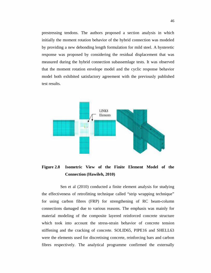
Hawileh et al (2010) developed three dimensional nonlinear finite
element model to predict the behavior of precast hybrid beam-column
connection subjected to cyclic loading. The precast joint was modeled using
three dimensional solid elements and surface-to-surface contact elements
between the beam/column faces and interface grout in the vicinity of the
connection. The solid element SOLID65 was used to model the concrete. The
primary reinforcement post-tensioned strands and mild steel reinforcement
bars were modeled as solid elements SOLID185 because they were debonded
from the adjacent concrete surfaces in the vicinity of the connection. The
regular beam and column reinforcement are discretized using the discrete spar
elements. Perfect bond was assumed between the reinforcing steel and
concrete element. In this structure, the beam and column faces are in contact
with the interface grout, and there was also contact between the mild steel
bars and grout in the vicinity of the connection. Two element types
CONTA174 and TARGE170 were used for the contact and target surfaces
since the contact were between the two different surfaces. Surfaces with finer
mesh were designated as contact surface while surfaces with coarser meshes
were considered target surfaces. Results showed that the response envelope
from the finite element analysis correlated fairly well with the experimental
results. Good correlation existed in all stages of lateral cyclic loading.
Isometric view of the finite element model of the connection is shown in
Figure 2.8.
Ozden and Ertas (2010) presented an alternative section analysis
and hysteretic modeling for the response of precast concrete hybrid
connections which had different level of mild steel contributing to the
connection flexural capacity. It was suggested that the well known classical
reinforced concrete section analysis approach cannot be directly applied to the
precast concrete hybrid connections due to the strain compatibility between
the concrete sections and the partially bonded mild steel and the unbounded
46
prestressing tendons. The authors proposed a section analysis in which
initially the moment rotation behavior of the hybrid connection was modeled
by providing a new debonding length formulation for mild steel. A hysteretic
response was proposed by considering the residual displacement that was
measured during the hybrid connection subassemlage tests. It was observed
that the moment rotation envelope model and the cyclic response behavior
model both exhibited satisfactory agreement with the previously published
test results.
Figure 2.8 Isometric View of the Finite Element Model of the
Connection (Hawileh, 2010)
Sen et al (2010) conducted a finite element analysis for studying
the effectiveness of retrofitting technique called “strip wrapping technique”
for using carbon fibres (FRP) for strengthening of RC beam-column
connections damaged due to various reasons. The emphasis was mainly for
material modeling of the composite layered reinforced concrete structure
which took into account the stress-strain behavior of concrete tension
stiffening and the cracking of concrete. SOLID65, PIPE16 and SHELL63
were the elements used for discretising concrete, reinforcing bars and carbon
fibres respectively. The analytical programme confirmed the externally

47
bonded Fibre Reinforced Polymer (FRP) using carbon fibre with a new
technique called strip wrapping technique was a promising and a viable
solution towards enhancing the strength and stiffness characteristics of the
beam-column joints.
Wang et al (2010) conducted a nonlinear analysis of steel concrete
composite beam to concrete filled steel tubular column joints. In this study,
elastoplastic constitutive model based on the increment theory was used to
describe the constitutive relation of concrete. The model used William
Warnke five parameter yield criterion, uniform strength criterion and
associated flow criterion. A simplified Varma’s model was taken as the
constitutive relation for steel which considered dynamic hardening and local
buckling. SOLID65 was used to simulate concrete. This finite element model
can simulate wrapped tension cracking, crush, plastic deformation and creep
of concrete in three orthogonal directions. SHELL181 element was used to
simulate wrapped steel, strengthened ring and steel tubular. This finite
element model can simulate stress stiffening and large deformation of these
materials. LINK8 element which was the tension-compression element along
the axis was chosen to simulate the bar. COMBIN39 element was used to
simulate the contact and slip between wrapped steel, steel tubular and
concrete. The hysteresis curves of FEA calculation and the experimental
values were found to match well during the elastic stage. The authors
observed that because of the different loading mechanism and the difference
of finite element model and the specimen, the differences of them increased
under cyclic loading. However, the shape rules of the curves remained the
same.
Dere and Dede (2011) studied the failure behavior and crack
formation of a reinforced concrete frame under monotonic and reversed cyclic
lateral loading by three dimensional nonlinear finite element analysis using

48
ANSYS software. Concrete was modeled as SOLID65 element. For modeling
reinforcement smeared reinforcement option was preferred as it was easy and
reliable. The load displacement envelopes obtained from ANSYS analysis and
experimental data were compared and found to be in good agreement with
each other. The crack profiles obtained from ANSYS model compared with
that of the experiments. The finite element model showed larger number of
cracks but the crack locations compared well with the experiments.
2.2.2.3 Precast Wall, Slab and Column
Xiao and Flaherty (2000) conducted finite element analysis of slab
column connections. The ANSYS finite element package was used for
modeling. SOLID65 element was used to model concrete. This element can
represent both linear and nonlinear behavior of the concrete. The flexural
reinforcement was defined using smeared reinforcement approach. The
compressive stress-strain relationship represented using two types of curves.
Firstly, a bilinear curve (perfectly plastic model) and secondly a multi-linear
curve (strain softening curve) was used. The main focus of this analysis was
to model the load deflection behavior of the specimen. The nonlinear
procedures of the finite element package cannot handle negative gradients in
the stress-strain curve, therefore the stress was not allowed to fall before
failure occurred. Hence the curve upon yielding was maintained horizontal up
to failure or was given a slight positive gradient to help converge of the
solution. The numerical investigations provided good agreement between the
predicted and the measured test results of the ultimate load and the associated
deflection.
Belakhdar (2008) developed a nonlinear finite element model for
evaluating the behavior of reinforced concrete slabs strengthened with shear
bolts under transverse load. The concrete was modeled as eight noded brick
elements. The flexural reinforcement and the shear bolts were modeled as

49
truss elements. A perfect bond was assumed between the brick element and
truss element. The nonlinear behavior of concrete in compression was
simulated by an elastio-plastic work-hardening model and in tension a
suitable post-cracking model based on tension stiffening and shear retention
models were employed. The steel was simulated using an elastic-full plastic
model. The validity of the theoretical formulations and the program used was
verified through comparison with available experimental data and the
agreement had proven to be good.
Kheyroddin and Naderpour (2008) conducted an analytical and
parametric study on the effectiveness of using externally bonded steel plates
and Fibre Reinforced Polymer (FRP) on reinforced concrete shear walls as a
retrofit technique to improve the seismic behavior. The solid element
SOLID65 in the ANSYS program was used in the analysis. The plasticity
model for concrete was based on the flow theory of plasticity, Von Mises
yield criterion, isotropic hardening and associated flow rule. The shear
transfer coefficient t represented conditions of the crack face. The value of t
ranges from 0 to 1.0, with 0 representing smooth crack and 1.0 representing
rough crack. The shear transfer coefficient used for this study was equal to
0.2. The shear transfer coefficient for a closed crack was taken as 1.0. The
externally bonded steel plates were modeled as SOLID45 element. A layered
solid element, SOLID46 was used to model FRP composites. From
verification against the experimental data it was concluded that the finite
element program can be used to simulate the whole load deformation curve,
the elastic part, the initiation of cracking, shear cracks and crushing fairly
well.
Tavio and Tata (2009) presented a non-linear finite element
modeling and analysis of rectangular normal strength reinforced concrete
columns confined with transverse steel under axial compressive loading. The

50
columns were modeled as discrete elements using ANSYS nonlinear finite
element software. Concrete and reinforcement were modeled as 8 noded
SOLID65 elements and 3D- LINK8 bar elements respectively. The non-linear
constitutive law of each material was also implemented in the model. The
results indicate that the stress-strain relationships obtained from the analytical
model using ANSYS are in good agreement with experimental data. This was
confirmed with the insignificant difference between the analytical and
experimental results (i.e) 5.65 and 2.8 percent for the peak stress and strain at
peak stress, respectively. The actual stress-strain relationship, the strength
gain and ductility improvement have also been confirmed to be satisfactory.
2.3 SUMMARY
From the literatures, it is observed that the precast connections can
be detailed as strong as that of the monolithic connections. It is also
understood that the dry connections have better energy dissipation
characteristics. Hence, for the present study seven types of simple mechanical
connections have been adopted for the experimental investigations under
reversed cyclic loading. From the literatures, it was decided to use the finite
element package ANSYS for modeling. Information about the elements to be
used in modeling the various materials was also studied. It was concluded
that, for modeling precast connection in ANSYS the most appropriate
elements to be used are SOLID65, LINK8, CONTACT174, TARGET170,
and SOLID45. Also data input in material model to simulate concrete to
behave in multi-linear, elastic and inelastic stages are decided from the
literature study. From the experience of past researchers, possibilities and
reasons of error and approximations were also studied. The advanced
methodologies can be adopted for the better modeling and analysis of various
structural elements.