chapter 2 - conduction(a)-steady state
DESCRIPTION
Heat TransferTRANSCRIPT

CHAPTER 2
Conduction
1) Steady state conduction2) Unsteady state conduction
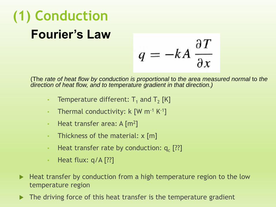
(1) Conduction
• Temperature different: T1 and T2 [K]
• Thermal conductivity: k [W m-1 K-1]
• Heat transfer area: A [m2]
• Thickness of the material: x [m]
• Heat transfer rate by conduction: qc [??]
• Heat flux: q/A [??]
Fourier’s Law
(The rate of heat flow by conduction is proportional to the area measured normal to thedirection of heat flow, and to temperature gradient in that direction.)
Heat transfer by conduction from a high temperature region to the low
temperature region
The driving force of this heat transfer is the temperature gradient

Fourier’s Law
Thermal conductivity, k
Experiment measurement made to
determine the value of k (different
material, different k)
The k value is a physical property
of each solid, liquid and gas
material
k is strongly temp-dependent
Unit W m-1 K-1
The numerical value of k indicates
how fast heat will flow in a
given material.
If molecules move fasters (gas),
the faster they will transport
energy.
So, value of k depends on the
molecules structure (gas, liquid or
solid) K of various materials at 0 °C

Thermal conductivity, k
Why we should know k of each
material???

(2) ConvectionNewton’s law of cooling
Temperature different between wall and fluid: Tw and Tf [K]
Convective heat transfer coefficient: hcv [W m-2 K-1]
Heat transfer area: A [m2]
Heat transfer rate by convection: qcv [??]
Heat flux: q/A [??]
Also referred to as the “Newton rate equation” or “Newton’s law of
cooling”
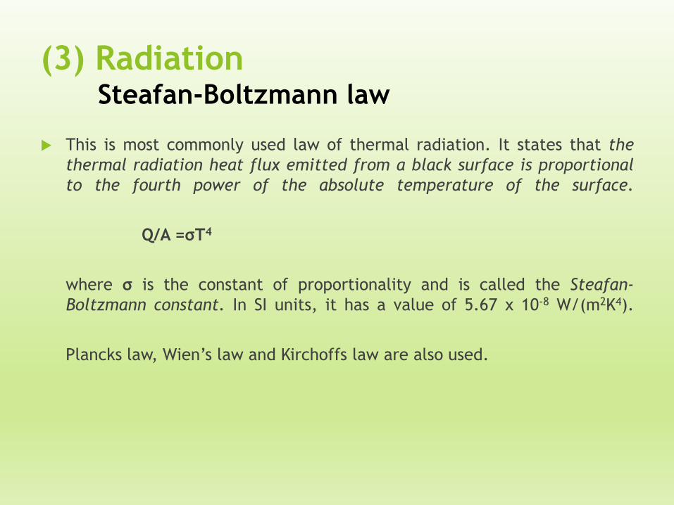
(3) RadiationSteafan-Boltzmann law
This is most commonly used law of thermal radiation. It states that the
thermal radiation heat flux emitted from a black surface is proportional
to the fourth power of the absolute temperature of the surface.
Q/A =σT4
where σ is the constant of proportionality and is called the Steafan-
Boltzmann constant. In SI units, it has a value of 5.67 x 10⁻⁸ W/(m2K4).
Plancks law, Wien’s law and Kirchoffs law are also used.

Steady State Conduction- One Dimension (1D)-

Point of view
Application of Fourier’s law of heat conduction to calculation of heat flow in simple 1D system
(1) Plane Wall
(2) Cylinders
(3) Spherical
1D The temp. in the body is a functiononly of radial distance andindependent of azimuth angle/axial distance
Radial Systems

(1) The Plane Wall
Integrated Fourier’s law
If k varies with temp.
according linear relation, the heat flow become;
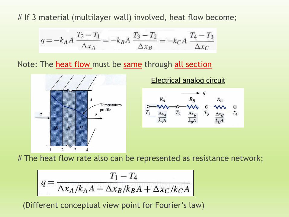
# If 3 material (multilayer wall) involved, heat flow become;
Note: The heat flow must be same through all section
# The heat flow rate also can be represented as resistance network;
(Different conceptual view point for Fourier’s law)
Electrical analog circuit

Consider Heat transfer rate as flow and combination of as a resistance to this flow. The temp. is the potential function of the heat flow. So that, the Fourier equation may be written as:
3 wall side by side act as 3 thermal resistance in series
Electrical analog circuit: used to solve more complex problem (series and parallel thermal resistance)
Thermal resistance (°C/W)

Electrical analog circuit
Parallel
Series

Insulation & R value
The performance of insulation R value, define as
The units for R is °C m2 /W
Guide to choose insulating material in terms of their application and allowable temperature range

(2) Cylinders (Radial System)
From Fourier’s Law
For a cylinder with length very large compared to diameter, it may be assumed that the heat flows only in a radial direction

Thermal resistant for cylinder is
Boundary conditions
The heat flow rate
Electrical analog circuit

Multiple cylindrical sections
Thermal-resistance concept for
multiple-layer cylindrical walls =
Thermal-resistance concept for
plane wall
So that, the heat flow rate
Electrical analog circuit

(3) Spheres
The heat flow rate
Prove this equation!!

Convection Boundary Conditions
Newton rate equation /Newton’s Law of cooling
So that, an electric-resistance analogy for convection process become:

Example 1: (Multilayer plane wall conduction)
An exterior wall of a house may be approximated
by a 4-in layer of common brick (k= 0.7 W/m.°C)
followed by a 1.5-in layer of gypsum plaster
(k=0.48 W/m.°C). What thickness of loosely
packed rock wool insulation (k=0.065 W/m.°C)
should be added to reduce the heat loss (or gain)
through the wall by 80%?
Answer: ∆xinsulation= 0.0584 m

Example 2: (Multilayer Cylindrical System)
A thick-walled tube of stainless steel [18% Cr, 8% Ni, k=19
W/m.°C ] with 2 cm inner diameter (ID) and 4 cm outer
diameter (OD) is covered with a 3 cm layer of asbestos
insulation [k=0.2 W/m.°C ]. If the inside wall temperature of
the pipe is maintained at 600 °C, calculate the heat loss per
meter of length. Also calculate the tube-insulation interface
temperature.
Answer: Tinsulation= 596. °C
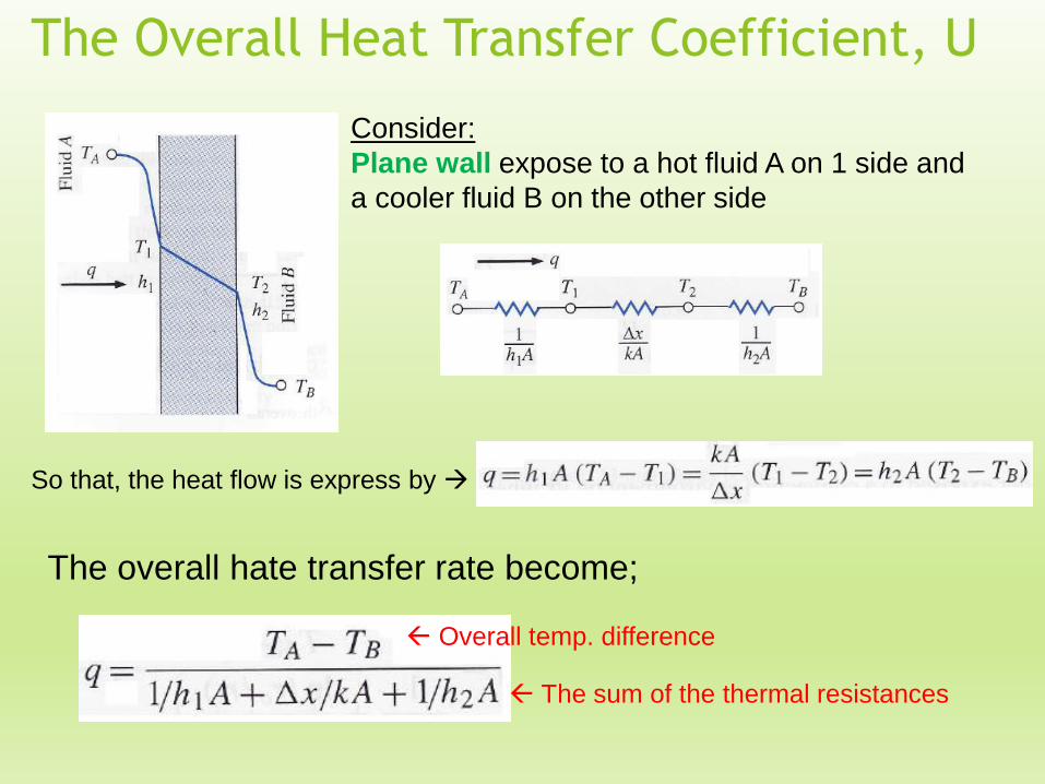
The Overall Heat Transfer Coefficient, U
Consider:
Plane wall expose to a hot fluid A on 1 side and
a cooler fluid B on the other side
So that, the heat flow is express by
The overall hate transfer rate become;
Overall temp. difference
The sum of the thermal resistances

The Overall Heat Transfer Coefficient, U
1/ h A represent the convection resistance;
∆x/ k A represent the conduction resistance
The overall heat transfer (conduction + convection) can be expressed in term of
an overall heat transfer coefficient, U defined by relation:
The Overall Heat Transfer Coefficient
U also related to the R-value:
Where,
A: Area for the heat flow

Consider:
Hollow cylinder exposed to a convection
environment on its inner and outer surfaces with TA
and TB the two fluid temp. The area for convection is
not same for both liquids (depend on the inside tube
diameter and wall thickness
The Overall Heat Transfer Coefficient, U
The overall hate transfer rate become;
Overall temp. difference
The sum of the thermal resistances

The Overall Heat Transfer Coefficient, U
Ai & Ao: Inside & outside surface areas of the inner tube
The Overall Heat Transfer Coefficient (Hollow cylinder)
based on:
1) Inside area of the tube Ai
2) Outside area of the tube, Ao
The Overall Heat Transfer Coefficient, U
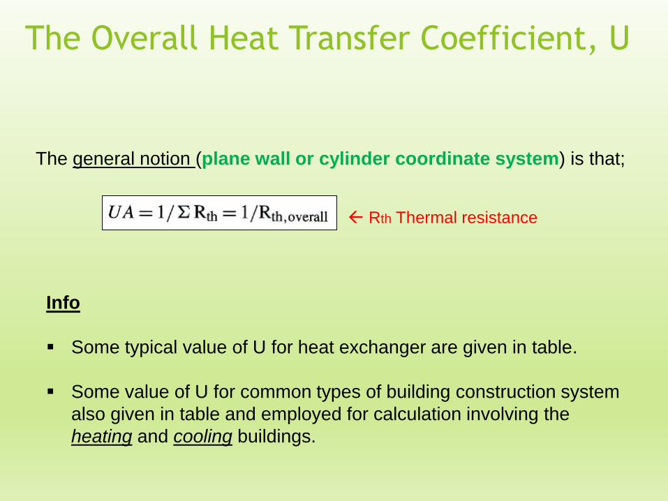
The general notion (plane wall or cylinder coordinate system) is that;
Rth Thermal resistance
Info
Some typical value of U for heat exchanger are given in table.
Some value of U for common types of building construction system
also given in table and employed for calculation involving the
heating and cooling buildings.

Example 3
A house wall may be approximated as two 1.2 cm layers of
fiber insulating board, an 8.0 cm layer of loosely packed
asbestos, and a 10 cm layer of common brick. Assuming
convection heat transfer coefficient of 12 W/m2. °C on both
sides of the wall, calculate the overall heat transfer coefficient
for this arrangement.
Answer: U= 0.6221 W/m2. °C

Example 4
A wall is constructed of a section of stainless steel [k=16 W/m.
°C] 4.0 mm thick with identical layers of plastic on both sides
of the steel. The overall heat transfer coefficient, considering
convection on both sides of the plastic, is 120 W/m2.°C. If the
overall temp. different across the arrangement is 60 °C,
calculated the temperature difference across the stainless
steel.
Answer: Tss= 18 °C
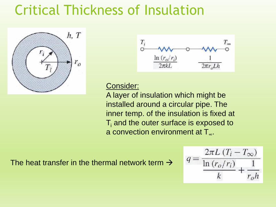
Critical Thickness of Insulation
Consider:
A layer of insulation which might be
installed around a circular pipe. The
inner temp. of the insulation is fixed at
Ti and the outer surface is exposed to
a convection environment at T∞.
The heat transfer in the thermal network term

Critical Thickness of Insulation
The result is The critical-radius-of insulation concept
Manipulated this equation to determine the outer radius of
insulation, ro, which will maximize the heat transfer. The
maximization condition is :

1) If ro < critical radius value, means:
The critical-radius-of insulation concept
Critical Thickness of Insulation
Concept
The heat transfer will be increased by adding more insulation
thickness
2) If ro > critical radius value, means:
The heat transfer will be decrease by adding more insulation
thickness

Calculate the critical radius of insulation for
asbestos [k =0.17 W/m◦C] surrounding a pipe
and exposed to room air at 20◦C with h=3.0 W/m2
◦C. Calculate the heat loss from a 200◦C, 5.0-cm-
diameter pipe when covered with the critical
radius of insulation and without insulation
Answer: q/L with insulation =105.7W/m
q/L without insulation =84.8W/m
Example 5

Book: J.P. Holman
1) 2-8
2) 2-9
3) 2-17
4) 2-18
5) 2-26
6) 2-62
Problems