chapter 16 networks and protocols - utoledo.edu
TRANSCRIPT

Ch. 16 Networks and Protocols 1
Chapter 16 NETWORKS and PROTOCOLS
Definition of Protocol
A protocol is a specification for standardized packets of data. Moving packets of data is the
method that allows networks to share information. Packets of information move through the
protocol stack and then move across the transmission media.
Introduction
In their web-based documentation of Windows 2000, Microsoft details how TCP/IP came about:
“TCP/IP is an industry-standard suite of protocols designed for large internetworks spanning
wide area network (WAN) links. TCP/IP was developed in 1969 by the U.S. Department of
Defense Advanced Research Projects Agency (DARPA), the result of a resource-sharing
experiment called ARPANET (Advanced Research Projects Agency Network). The purpose of
TCP/IP was to provide high-speed communication network links. Since 1969, ARPANET has
grown into a worldwide community of networks known as the Internet.”
Ethernet, TCP/IP and other networking principles are subjects too vast to be expanded here. It is
important for the student to master the principles of networking, however, as they pertain to the
factory floor. The use of addresses is discussed when setting up some devices. Other
networking issues will need to be discussed since the move of Ethernet from the business side of
the factory to the factory floor has been underway long enough for equipment to be available
with Ethernet connectivity.
DeviceNet
DeviceNet is a relatively easy I/O network to install and configure. First will be an introduction
to CanBus. Then the organization, ODVA, through which DeviceNet is governed, will be
discussed. The software RSNetworx for Devicenet will explain the mapping of I/O to the
processor. While this local network is on the wane today, it will be explored since it was a recent
attempt by the user to address local area network problems in the industrial environment.
CanBus
CanBus or CAN.bus is a two-wire differential serial bus. It is designed to operate in noisy
electrical environment. The CanBus system also guarantees a high degree of data integrity
between components. It is also an open architecture which means that many companies are
encouraged to design components and systems for its use. CanBus is capable of high-speed data
transmission (up to 1 Mbits/s) in short distance applications. It can also operate at longer range
but with lower speeds. CanBus is multi-master with a high fault tolerance and error detection
capability.
CanBus was originally developed in Germany by Bosch and was designed to replace electrical
sensor components in the automobile. The design allowed a smaller wiring harness than was the
design standard prior to CanBus. This bus was also recognized as an ideal bus for the industrial
market but the automotive market has remained as its primary focus.
CanBus is especially well adapted for working with intelligent devices in a system or sub-system.
CanBus has become the standard for IVN or in-vehicle network applications. Applications

Ch. 16 Networks and Protocols 2
include power-train applications for automobiles as well as between the truck and trailer in truck
applications. One author described CanBus in the following way: “Many American and
European truck and bus manufacturers have implemented CAN-based IVNs, and more and more
truck-based superstructure control systems (e.g. fire fighting equipment and concrete mixers)
also use CAN as their embedded control network.”
The description continues: “CAN is often used as the embedded network to run functions such as
the power-train, body electronics, super-structure control and trailer communications. Likewise,
CAN is also used to run add-on sub-systems such as harvesters, cranes, winches, drums, etc. In
cases where several CAN-based IVNs are used to run multiple functions, these IVNs may be
interconnected via gateways. This keeps the systems separate to avoid interferences and
disturbances that may be caused if all operations run simultaneously in one physical layer.”
An article in the October, 2003 issue of Control Engineering identifies a question concerning the
use of CanBus or Device Net and its competitor, Ethernet. In the article, Colin MacDonald
writes:
“In choosing the appropriate network bus to support, a designer should ask several questions:
Will both CAN and Ethernet continue to be widely adopted? If so, how will they co-exist? And
finally, how will the choice of buses affect the design of network processors?
New Software to Learn
When starting a new DeviceNet application, it is necessary to become familiar with a new
software product from Allen-Bradley called RSNetWorx for DeviceNet. A DeviceNet Scanner
Card will be installed in both a SLC 5/03 and in a CompactLogix processor. With
CompactLogix, the newer RSLogix 5000 software programming package will be necessary.
This may be the first exposure for students with this software package as well as RSNetWorx for
DeviceNet.
Notice that in the above figure, the network screen for DeviceNet shows no devices on the graph
portion of the screen. This shows a new network with no devices attached. Also notice the note
in the description section in the message box. Copy protection was not installed in this instance
on the software and the software will run in this instance in demo mode only which allows only
six nodes to be attached.
Fig. 16-1
Devicenet Network
Configured in the A-B
RSNetWorx Software

Ch. 16 Networks and Protocols 3
SLC 5/03
In the figure above, the DeviceNet scanner is being added to the rack’s I/O configuration. Notice
the maximum input and output word count for the SDN module listed under Advanced I/O
Configuration. This is the maximum number of data words available for the scanner module to
share with this SLC 5/03 PLC. The scanner is located in slot 1.
CompactLogix Processor
The figure above shows the method of adding the scanner card to the CompactLogix I/O
configuration. Notice the type is 1769-SDN/B. Cards must be added to the I/O list in RSLogix
5000 and not read from the I/O as was possible in RSLogix 500. This scanner is also located in
slot 1.
Fig. 16-2
Adding the DeviceNet
Scanner to the SLC 5/03
Fig. 16-3
Adding the DeviceNet
Scanner to the
CompactLogix
Processor
Ch. 16 Networks and Protocols 4
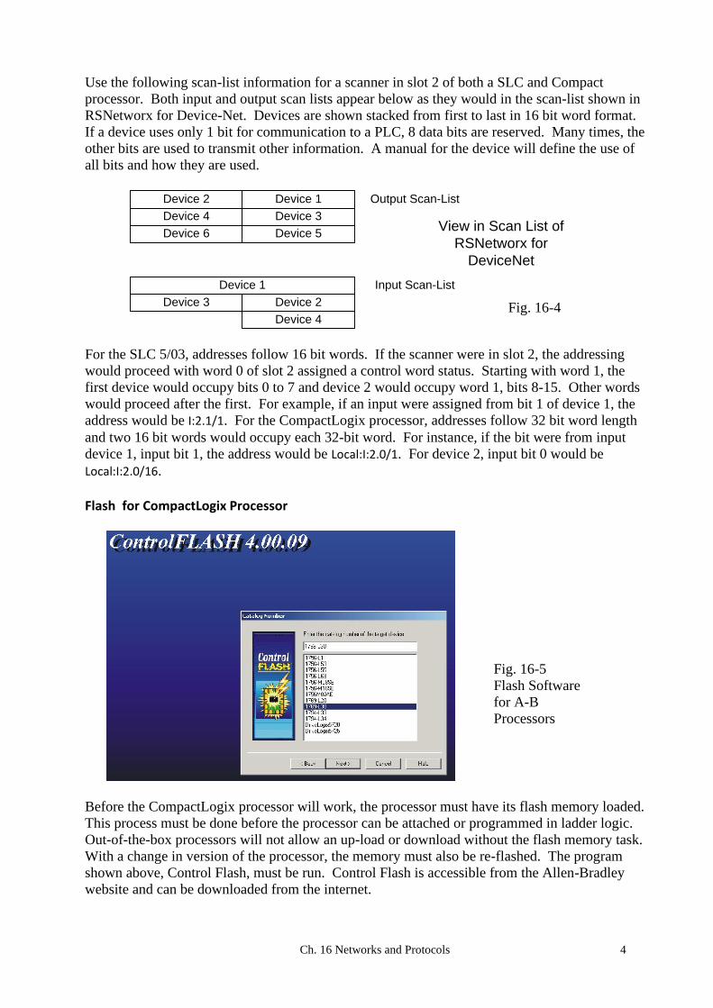
Use the following scan-list information for a scanner in slot 2 of both a SLC and Compact
processor. Both input and output scan lists appear below as they would in the scan-list shown in
RSNetworx for Device-Net. Devices are shown stacked from first to last in 16 bit word format.
If a device uses only 1 bit for communication to a PLC, 8 data bits are reserved. Many times, the
other bits are used to transmit other information. A manual for the device will define the use of
all bits and how they are used.
Device 2 Device 1
Device 4 Device 3
Device 6 Device 5
Output Scan-List
Device 1
Device 3 Device 2
Device 4
Input Scan-List
View in Scan List of
RSNetworx for
DeviceNet
For the SLC 5/03, addresses follow 16 bit words. If the scanner were in slot 2, the addressing
would proceed with word 0 of slot 2 assigned a control word status. Starting with word 1, the
first device would occupy bits 0 to 7 and device 2 would occupy word 1, bits 8-15. Other words
would proceed after the first. For example, if an input were assigned from bit 1 of device 1, the
address would be I:2.1/1. For the CompactLogix processor, addresses follow 32 bit word length
and two 16 bit words would occupy each 32-bit word. For instance, if the bit were from input
device 1, input bit 1, the address would be Local:I:2.0/1. For device 2, input bit 0 would be
Local:I:2.0/16.
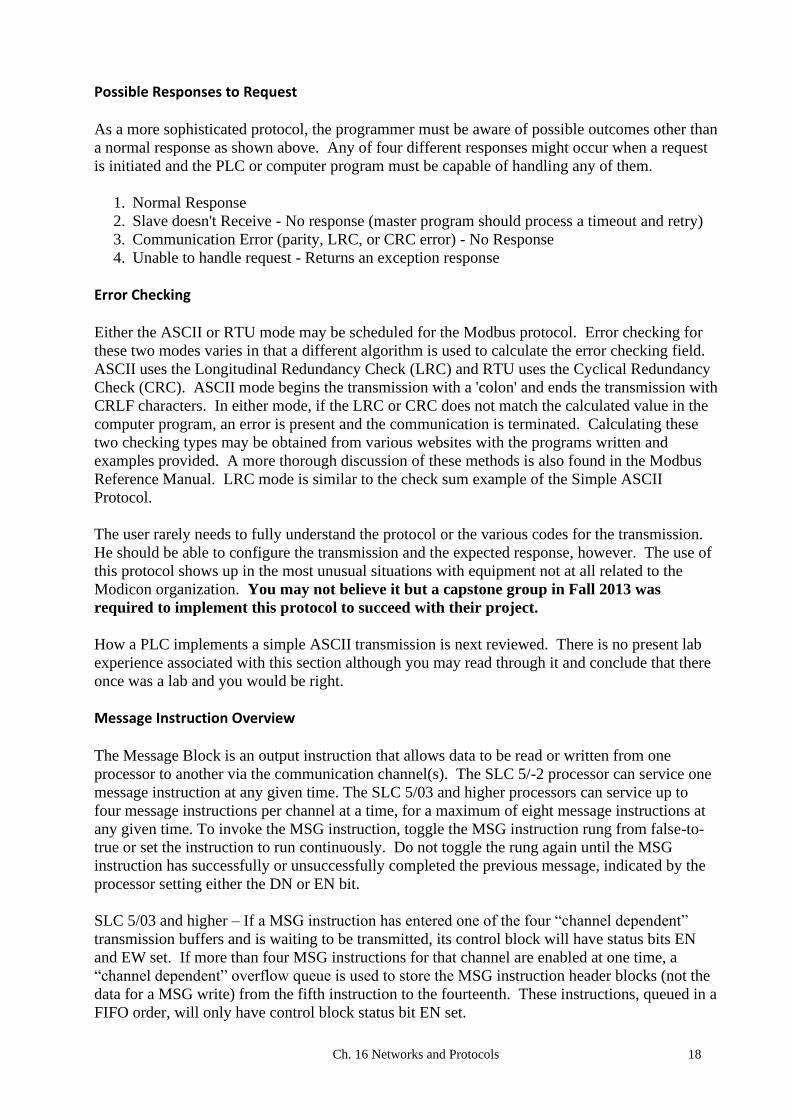
Flash for CompactLogix Processor
Before the CompactLogix processor will work, the processor must have its flash memory loaded.
This process must be done before the processor can be attached or programmed in ladder logic.
Out-of-the-box processors will not allow an up-load or download without the flash memory task.
With a change in version of the processor, the memory must also be re-flashed. The program
shown above, Control Flash, must be run. Control Flash is accessible from the Allen-Bradley
website and can be downloaded from the internet.
Fig. 16-4
Fig. 16-5
Flash Software
for A-B
Processors

Ch. 16 Networks and Protocols 5
ASCII READ/WRITE BLOCKS and PROTOCOLS: Introduction Computers use numeric codes to transfer information to a PLC and other control devices.
Various sets of numeric codes have been implemented to transfer text information between
computers. One of these codes is ASCII. ASCII stands for American Standard Code for
Information Interchange. As can be seen from the table of ASCII characters in the ASCII Table
later in the chapter, not all codes represent letters or numbers. Many codes represent actions,
special keys or control characters.
The chapter explains the use of ASCII codes to transmit information between computers. One
computer capable of transmitting and accepting ASCII coded data is the PLC. The SLC 5/03 as
well as a number of other PLCs is capable of reading and writing ASCII string data through its 9
pin D-shell connector on the CPU front panel. Instructions for transfer of data are found in
Allen-Bradley’s SLC 500 Instruction Set Reference Manual, Chapter 10.
Writing a program to communicate between computer controllers involves handling of ASCII
codes or other numeric data in order to move information or request an action. Many of these
programs use ASCII data to accomplish the task. A mixture of ASCII data and other numeric
data is the norm for most tasks. A second data transmission type is RTU (Remote Terminal
Unit) with a more dense data packet. Use of RTU will be discussed as well in the chapter.
Definition of the communication between two controllers is included in a protocol. Many
protocols are very simple and require only a simple description of the query and any expected
response.
Then a more complete protocol is explored. How one controller requests information from
another device and how that device responds is the basis for an advanced protocol. Contents of
various fields in the protocol are described so the protocol can function properly.
Configuring a PLC for ASCII Read/Write
The figure above shows the Channel Configuration setting change that must take place prior to
using the port as an ASCII port. Channel 0 must be changed from System to User.
Fig. 16-6
Using the SLC
Processor as
ASCII Device

Ch. 16 Networks and Protocols 6
Many devices use ASCII code to transmit information. Scales send weights from the scale
computer to a batching computer. Bar code readers send bar code data to a sorting computer.
RFID tag readers send tag information to and from the tag and communicate to a computer
system controlling the process. PLCs have the ability to read and write ASCII strings of data
from these devices and are used to gather data and control processes using the string data.
A new file type is needed to hold ASCII string information, the String file type. It is added to the
Data File list as follows:
File, Data Files, Select Data File and from below, Create New:
The process of creating a new file may also be done by right clicking Data Files and then choosing
Add New. The example below shows the adding of File 9 as a String file. Files do not necessarily
need to be added sequentially although most applications tend to reserve File 9 as a String or
ASCII file type.
Fig. 16-7a
Configure the
String or
ASCII file in
the SLC
Fig. 16-7b
Configure the
String or
ASCII file in
the SLC

Ch. 16 Networks and Protocols 7
Table of ASCII Characters ASCII characters are transmitted sequentially a bit at a time through a serial data cable. Each bit
is transmitted sequentially starting with the left-most bit. Two start bits and 1, 1.5, or 2 stops
may be specified. The channel may be configured from RSLogix 500 using the project tree –
channel configuration, channel 0, and then user. From this tab, choose the baud rate, parity, stop
bits and data bits to be used. Typical choices are 9600 baud, no parity, 1 stop bit and 8 data bits.
For protocol control, chose Control Line – no handshaking – and for Delete Mode – ignore.
Echo and XON/XOFF are usually left unchecked. The important point about these settings is
that they must match the settings with the other device.
Looking at a transmission on the oscilloscope may yield good information. Storage
oscilloscopes are definitely superior to non-storage oscilloscopes for this job. Transmissions
should be visible per character with start and stop bits present as well as data bits of the 7 or 8 bit
character string. For instance, the character “:” from the ASCII Table is 00111010 binary. With
two start bits and one stop bit, it would resemble the following on the oscilloscope:
1 1 1 1 1 1 10 0 Fig. 16-8 Oscilloscope Representation of ASCII Character
Transmission Modes and ASCII Tables
The advanced protocol discussed later in this chapter is set up to communicate in one of two
types of transmission: ASCII or RTU. This protocol will be discussed more completely later in
the chapter. The choice of ASCII or RTU is made by the system designer and must be kept the
same throughout. While this example shows only the transmission for a standard Modbus
network, it shows a typical transmission for a computer to computer data exchange.
From the manual defining the Modbus protocol, one finds the two following serial transmission
diagrams, one for ASCII and the other for RTU data transmission. The data is sent in the order
defined by the diagram from left to right:
ASCII with Parity Checking
START 1 2 3 4 5 6 7 PRTY STOP
START 1 2 3 4 5 6 7 STOP
START 1 2 3 4 5 6 7 PRTY STOP
START 1 2 3 4 5 6 7 STOP
STOP
ASCII without Parity Checking
8
RTU with Parity Checking
8 STOP
RTU without Parity Checking
Fig. 16-9
Modbus
Protocol
Frames

Ch. 16 Networks and Protocols 8
ASCII Mode in Modbus Protocol
In the Modbus protocol, each 8–bit byte is set up to be sent in a message as two separate ASCII
characters. This protocol gives the following rules for coding data in a message as: (from the
Modbus manual)
"Coding System:
Hexadecimal, ASCII characters 0–9, A–F One hexadecimal character contained in each ASCII character of the message Bits per Byte: 1 start bit 7 data bits, least significant bit sent first 1 bit for even/odd parity; no bit for no parity 1 stop bit if parity is used; 2 bits if no parity
Error Check Field: Longitudinal Redundancy Check (LRC)"
RTU Mode in Modbus Protocol
In the Modbus protocol, each 8-bit byte transmits two hexadecimal characters in the RTU mode.
This protocol gives the following rules for coding data in a message as: (from the Modbus
manual)
"Coding System: 8–bit binary, hexadecimal 0–9, A–F Two hexadecimal characters contained in each 8–bit field of the message Bits per Byte: 1 start bit 8 data bits, least significant bit sent first 1 bit for even/odd parity; no bit for no parity 1 stop bit if parity is used; 2 bits if no parity Error Check Field: Cyclical Redundancy Check (CRC)"
In general, while ASCII may be configured as either 7 or 8 bit, the standard ASCII table
identifies only 128 characters. With the Modbus protocol defined above, 7 bit ASCII is
sufficient and is required per the protocol. ASCII protocol is less efficient in the Modbus
protocol than RTU, in that for each transmission, only 4 bits of data is transmitted. With RTU, 8
bit must be selected since 8 bits define 8 bits or one byte of data to be transmitted.
The table that follows is the standard set of ASCII characters:

Ch. 16 Networks and Protocols 9
Char Dec Oct Hex | Char Dec Oct Hex | Char Dec Oct Hex | Char Dec Oct Hex
-------------------------------------------------------------------------------------
(nul) 0 0000 0x00 | (sp) 32 0040 0x20 | @ 64 0100 0x40 | ` 96 0140 0x60
(soh) 1 0001 0x01 | ! 33 0041 0x21 | A 65 0101 0x41 | a 97 0141 0x61
(stx) 2 0002 0x02 | " 34 0042 0x22 | B 66 0102 0x42 | b 98 0142 0x62
(etx) 3 0003 0x03 | # 35 0043 0x23 | C 67 0103 0x43 | c 99 0143 0x63
(eot) 4 0004 0x04 | $ 36 0044 0x24 | D 68 0104 0x44 | d 100 0144 0x64
(enq) 5 0005 0x05 | % 37 0045 0x25 | E 69 0105 0x45 | e 101 0145 0x65
(ack) 6 0006 0x06 | & 38 0046 0x26 | F 70 0106 0x46 | f 102 0146 0x66
(bel) 7 0007 0x07 | ' 39 0047 0x27 | G 71 0107 0x47 | g 103 0147 0x67
(bs) 8 0010 0x08 | ( 40 0050 0x28 | H 72 0110 0x48 | h 104 0150 0x68
(ht) 9 0011 0x09 | ) 41 0051 0x29 | I 73 0111 0x49 | i 105 0151 0x69
(nl) 10 0012 0x0a | * 42 0052 0x2a | J 74 0112 0x4a | j 106 0152 0x6a
(vt) 11 0013 0x0b | + 43 0053 0x2b | K 75 0113 0x4b | k 107 0153 0x6b
(np) 12 0014 0x0c | , 44 0054 0x2c | L 76 0114 0x4c | l 108 0154 0x6c
(cr) 13 0015 0x0d | - 45 0055 0x2d | M 77 0115 0x4d | m 109 0155 0x6d
(so) 14 0016 0x0e | . 46 0056 0x2e | N 78 0116 0x4e | n 110 0156 0x6e
(si) 15 0017 0x0f | / 47 0057 0x2f | O 79 0117 0x4f | o 111 0157 0x6f
(dle) 16 0020 0x10 | 0 48 0060 0x30 | P 80 0120 0x50 | p 112 0160 0x70
(dc1) 17 0021 0x11 | 1 49 0061 0x31 | Q 81 0121 0x51 | q 113 0161 0x71
(dc2) 18 0022 0x12 | 2 50 0062 0x32 | R 82 0122 0x52 | r 114 0162 0x72
(dc3) 19 0023 0x13 | 3 51 0063 0x33 | S 83 0123 0x53 | s 115 0163 0x73
(dc4) 20 0024 0x14 | 4 52 0064 0x34 | T 84 0124 0x54 | t 116 0164 0x74
(nak) 21 0025 0x15 | 5 53 0065 0x35 | U 85 0125 0x55 | u 117 0165 0x75
(syn) 22 0026 0x16 | 6 54 0066 0x36 | V 86 0126 0x56 | v 118 0166 0x76
(etb) 23 0027 0x17 | 7 55 0067 0x37 | W 87 0127 0x57 | w 119 0167 0x77
(can) 24 0030 0x18 | 8 56 0070 0x38 | X 88 0130 0x58 | x 120 0170 0x78
(em) 25 0031 0x19 | 9 57 0071 0x39 | Y 89 0131 0x59 | y 121 0171 0x79
(sub) 26 0032 0x1a | : 58 0072 0x3a | Z 90 0132 0x5a | z 122 0172 0x7a
(esc) 27 0033 0x1b | ; 59 0073 0x3b | [ 91 0133 0x5b | { 123 0173 0x7b
(fs) 28 0034 0x1c | < 60 0074 0x3c | \ 92 0134 0x5c | | 124 0174 0x7c
(gs) 29 0035 0x1d | = 61 0075 0x3d | ] 93 0135 0x5d | } 125 0175 0x7d
(rs) 30 0036 0x1e | > 62 0076 0x3e | ^ 94 0136 0x5e | ~ 126 0176 0x7e
(us) 31 0037 0x1f | ? 63 0077 0x3f | _ 95 0137 0x5f | (del) 127 0177 0x7f
Example of a Simple ASCII Protocol
Many times a two-way communication between devices requires a set sequence of characters that
define a proper communication. The protocol for the device below is a letter, a number (Head
Number), a check sum followed by an end of text character or <ETX>. Each communication
follows roughly the same simple pattern. A computer receives the request from the device and
responds with the appropriate information. The device initiates a request and gathers the results.
The examples below are between a computer and a radio-frequency identification system from
Peprl and Fuchs. Peprl and Fuchs literature defines each specific data type. For instance
<HdNo> refers to a specific head number in the range 1 to 4.
Command: A<HdNo><CHCK><ETX> Response: A<Status><DB><CHCK><ETX> Example: Read all data in Auto mode with read head 1: Command: A 1 72h 03h Read bytes, Single mode Command: w<HdNo><StAdrH><BytesH><CHCK><ETX> Response: w<Status><DB><CHCK><ETX> Read bytes, Auto mode Command: W<HdNo><StAdrH><BytesH>CHCK><ETX> Response: W<Status><DB><CHCK><ETX> Example: Read bytes 7 to 11 in Auto mode with read head 1: Command: W 1 07 05 54h 03h Write bytes, Auto mode Command: K<HdNo><StAdrH><BytesH><DB><CHCK><ETX> Response: K<Status><CHCK><ETX> Example: Write “P & F” to data carrier, at start address 10, in Auto mode with read head 2: Command: K 2 0A 03 50h 2Bh 46h 12h 03h
Fig. 16-10
Simple ASCII
Communication

Ch. 16 Networks and Protocols 10
To calculate a check sum <CHCK>, the following addition is performed: K 4Bh Ascii char "K"
2 32h Ascii char "2"
0 30h Ascii char "0"
A 41h Ascii char "A"
0 30h Ascii char "0"
3 33h Ascii char "3"
50h 50h hex char 50
2Bh 2Bh hex char 2B
46h + 46h hex char 46
(2)12h
This gives a check sum <CHCK> of 12h.
The check sum is used in many applications for error-checking. If the check sum does not equal
the calculated checksum, the data is discarded as bad. Check sum is also referenced as LRC or
Longitudinal Redundancy Check. It is a simple procedure giving a good check on validity of the
characters sent.
ASCII Instructions in the PLC
The SLC Instruction Set includes several ASCII instructions for reading and writing data from
the PLC.
Different applications require some or all of these instructions to accurately find information in
the string of data and use the information in the control of the process. AWA is ASCII Write
with append and AWT is an ASCII string write with no append. While the student may be at
first excited about the use of serial data transmission and writing a protocol, these programs are
among the most difficult to keep running in a factory environment. Noise may interfere with a
proper transmission and add a random character. A computer may not respond when asked.
Error recovery programs, time-outs, re-trys all become an integral part of any program to
implement one of these programs in a factory. Testing a procedure on the lab bench is usually
not enough to ensure success with this type of program in a field application.
Building A Test System
ASCII devices may need to be tested to prove data transmission. One of the best devices for
testing purposes is the personal computer. Use of Hyperterminal found on Windows-based
products is possible. A second terminal suggested is Br@y’s Terminal, a program downloadable
on your computer. The PLC and terminal must agree with all variables in the screen below:
The cable between the PLC and PC is an RS-232 cable with the transmit signal from one device
attached to the receive signal of the other device. Pin numbers are crossed with pin 2 of one
device connected to pin 3 of the other connector.
Be sure to use the PIC module to attach the SLC 5/03 to RSLogix500. Use Channel 1 for this
link. Channel 0 is now to be used as a simple ASCII port. It must be set for baud rate and parity
to match the Com1 port on the pc.
To send from the terminal, start typing. The character string will be transmitted a character at a
time. Many times the transmission occurs when the ‘enter’ key is pressed. To receive
characters, initiate communications from the PLC and watch for the character string to appear on
the pc terminal.

Ch. 16 Networks and Protocols 11
Example of ASCII Write in PLC
Fig. 16-12 Example of ASCII Write Instruction in SLC Processor
Notice above that the String file ST9:0 has text as follows: A1\72\03. This signifies that the
AWT command is used to write the A1 command followed by the CHCK of 72h followed by the
ETX or 03h.
Use of the oscilloscope to diagnose problems in serial transmissions is not common but may be
useful. With serial transmissions, use the oscilloscope as an arbitrator to find whether the device
really did transmit the string or the second device saw the character string and did not recognize
it. Storage scopes are best but with repeated character transmission, a non-storage scope will
also enable students to verify the data transmitted.
Full duplex communication allows the devices to respond when a transmission is received. To
test whether a communication has occurred, be sure to use the oscilloscope with the transmit lead
to neutral. The other lead is the receive lead.
A break-out box is also useful for testing transmissions. While a professionally made break-out
box is preferred, a simple connector to pins 2 and 3 of the cable and to pin 5 for the neutral will
work when used with the oscilloscope. This should be tried to verify that a character string is
being transmitted. If a storage oscilloscope is not available, continuous repeating of a character
transmitted from the terminal emulator should eventually be seen on the oscilloscope if set up
properly. Use of the oscilloscope in this kind of application may be the only way to verify that
the transmission of characters is actually occurring.
Data Transmissions
Devices transmit to or from Channel 0 User Port of the SLC 5/03 on an event. The port can
either send or collect characters in a buffer. If serial data is being collected at the port, the ASCII
read instruction sends the characters to a buffer when the expected number of characters in the
buffer is achieved. This type of transmission is prone to error and frustration. Noise in the data
transmission may be received as an extra character. Several of these noise characters may be
present and waiting in the print queue when a transmission occurs. As a result, what may work
well in the lab or on a test bench may not work at all or only marginally in a noisy factory
environment.

Ch. 16 Networks and Protocols 12
Many transmissions start with a special character – STX – to identify an authentic start-of-text
message. Other special characters to identify text include ETX or end-of-text.
Error-checking methods include check sum commonly referred to as LRC or the more
sophisticated CRC to verify data integrity. Check sum is a simple calculation of the addition of
all data bytes before the check sum. The data is added and any carry from the low byte is
ignored. The resulting check sum is transmitted and data is verified as good or not good based
on the check sum transmitted from the sending device and calculated from the receiving device.
Check sum calculations include the STX character sent with the transmission.
A More Complete Protocol
A protocol is a defined method by which computers communicate. A very early PLC protocol
first used by Modicon and the Modicon PLC family is the Modbus protocol. This protocol has
provided a standard for communication between various controllers since the late 1970s and
remains active today in a number of PLC and other industrial products. The protocol defines a
message stream that various controllers can recognize. Its inclusion here gives an example of a
more complete protocol with a more robust set of functions available. This protocol has survived
over the years due to its early acceptance, its flexibility, and its adaptability to a wide range of
control devices. A rigorous explanation of the protocol is found in Modicon's Modbus Protocol
Reference Guide.
From Modicon's Modbus Protocol Reference Guide*:
"It describes the process a controller uses to request access to another device, how it will respond to requests from the other devices, and how errors will be detected and reported. It establishes a common format for the layout and contents of message fields. The Modbus protocol provides the internal standard that the Modicon controllers use for parsing messages. During communications on a Modbus network, the protocol determines how each controller will know its device address, recognize a message addressed to it, determine the kind of action to be taken, and extract any data or other information contained in the message. If a reply is required, the controller will construct the reply message and send it using Modbus protocol."
The Modbus Transaction
The Modbus transaction is most typically used with an RS-232C serial interface. The RS-232C
designation defines connector pin-outs as well as other electrical and timing constraints on
signals between the communicating devices.
Modbus defines a master-slave protocol in which the master device queries the slave device
which then responds with its own transmission. A slave response is typically a table of data but
may include an action as requested by the master. A master may include computers or HMI
terminals but may also include other PLCs. A typical slave is a PLC or other control device.
Devices used as slave devices include any device from which control information is desired or
needs to be changed. A wide range of devices other than Modicon PLCs have adopted the
Modbus protocol and are programmed as Modbus slaves. Responses from slave devices range
from a single device response to a general broadcast query message to all slave devices on the
network.
Modbus provides a format for both master and slave protocols. From the figure on the next page,
a typical master query followed by a slave response is shown. In the query are information such

Ch. 16 Networks and Protocols 13
as the device address being communicated to, a function code, any data being sent or requested,
and an error checking field. This protocol is more sophisticated than the simple Peprl-Fuchs
protocol in that if an error occurs, the slave sends the appropriate error message.
* Modicon: Modbus Protocol Reference Guide
PI–MBUS–300 Rev. J
Device Address
Function Code
Data
Error Checking
Device Address
Function Code
Data
Error Checking
Device Address
Function Code
Data
Error Checking
Query from Master
Response from slave Response from slave
The Query: A query provides a function code requesting an action. The query may include any of the
following allowable function codes:
Code Name Comments * 01 Read Coil Status specifies 16*n discrete slave PLC outputs 02 Read Input Status specifies 16*n discrete slave PLC inputs 03 Read Holding Registers specifies n 16 bit words from slave PLC output tbl 04 Read Input Registers specifies n 16 bit words from slave PLC input table 05 Force Single Coil 06 Preset Single Register 07 Read Exception Status 08 Diagnostics 09 Program 484 84 specifies a type of Modicon PLC 10 Poll 484 11 Fetch Comm. Event Ctr. 12 Fetch Comm. Event Log 13 Program Controller 14 Poll Controller 15 Force Multiple Coils 16 Preset Multiple Registers 17 Report Slave ID 18 Program 884/M84 884/M84specifies a type of Modicon PLC 19 Reset Comm. Link 20 Read General Reference 21 Write General Reference 22 Mask Write 4X Register
Fig. 16-13

Ch. 16 Networks and Protocols 14
23 Read/Write 4X Registers 24 Read FIFO Queue
The function code field is followed by information in the master query telling the slave at which
word to begin and the number of words to read or write. Error checking provides a validation of
the message.
The Response:
The response is an echo of the function code found in the query plus any data requested followed
by the error checking byte or bytes. The new error checking provides the master with a
validation of the message and its contents.
Data Addresses Referenced to Zero
Every part of the data field in the Modbus protocol must be addressed correctly. For example,
the data address must be referenced to zero. From the Modbus Protocol manual, the following
examples show calculations of offsets for data addresses:
"The coil known as ‘coil 1’ in a programmable controller is addressed as coil 0000 in the data address field of a Modbus message. Coil 127 decimal is addressed as coil 007E hex (126 decimal). Holding register 40001 is addressed as register 0000 in the data address field of the message. The function code field already specifies a ‘holding register’ operation. Therefore the ‘4XXXX’ reference is implicit. Holding register 40108 is addressed as register 006B hex (107 decimal)."
Framing - ASCII
From the Modbus manual, the following:
"In ASCII mode, messages start with a ‘colon’ ( : ) character (ASCII 3A hex), and end with a ‘carriage
return – line feed’ (CRLF) pair (ASCII 0D and 0A hex). The allowable characters transmitted for all other fields are hexadecimal 0–9, A–F."
The typical transmission for a Modbus ASCII transmission resembles:
Start Address Function Data LRC Check End
1 Char :
2 Chars 2 Chars n Chars 2 Chars 2 Chars CRLF
Fig. 16-14 ASCII Transmission Frame
Framing - RTU
From the Modbus manual, the following:
"In RTU mode, messages start with a silent interval of at least 3.5 character times. This is most easily implemented as a multiple of character times at the baud rate that is being used on the network (shown as T1–T2–T3–T4 in the figure below). The first field then transmitted is the device address. The allowable characters transmitted for all fields are hexadecimal 0–9, A–F.

Ch. 16 Networks and Protocols 15
Networked devices monitor the network bus continuously, including during the ‘silent’ intervals. When the first field (the address field) is received, each device decodes it to find out if it is the addressed device. Following the last transmitted character, a similar interval of at least 3.5 character times marks the end of the message."
The typical transmission for a Modbus RTU transmission resembles:
Start Address Function Data CRC Check End
T1-T2-T3-T4 8 Bits 8 Bits n * 8 Bits 16 Bits T1-T2-T3-T4
Fig. 16-15 RTU Transmission Frame
Example Modbus Transmissions Description of "02" Read Input Status
The "02" request reads the status of discrete input points. The request is for inputs 197 to 218
from slave device 17.
Query
Hex 11 = Decimal 17 or the 17th deviceFunction 02 = Data Read from Digital Input Table starting at 10001High Address = 00Low Address = C4 or 12*16 + 4 or 192 + 4 = 196 which is address 10197 or 196 offset from 10001No of points = 16 or 1*16 + 6 = 22 data points
Sample Modbus Read Input Query
Response
Hex 11 = Decimal 17 or the 17th deviceFunction 02 = Data Read from Digital Input Table starting at 10001Byte Count = number of 8 bit bytes to be sent. There are 3 based on bit count of 22Data includes the first byte (AC), second byte (DB) and third byte (35). Notice that the third byte is not complete due to the fact that only 22, not 24 bits are desired. The extra two bits are not included and recorded as 0's.
Sample Modbus Read Input Response
Fig. 16-16

Ch. 16 Networks and Protocols 16
Explanation of Response:
The Slave Address is repeated from the query as 11. The function is also repeated from the
query as 02. Byte count is calculated from the number of bytes to be sent. The number of bytes
sent can be calculated by establishing the number of bytes necessary to send 16 hex data points.
The number 16 hex is equal to 22 decimal. If each input represents one data point, three 8-bit
bytes are needed for 22 data points. The data is sent from input addresses starting at offset C4
hex from the first data point 10001. The hex number C4 is equal to 12*16 or 192 plus 4 or total
196. The first data point is displaced 196 from 10001 or 10197. The first 8 data points reside in
addresses 10197 to 10204. The next eight reside in addresses 10205 to 10212. The final 6 reside
in addresses 10213 to 10218. Two bits are not used (10219, 10220). The data from these bits is
sent in three consecutive bytes. The value of 10197 through 10204 is shown in the first entry of
the figure below. Values of 10205 through 10212 are found in the second entry and values of
10213 to 10218 are found in the third.
10204 10203 10202 10201 10200 10199 10198 10197
1 0 1 0 1 1 0 0
A C
D B 3 5
10212 10211 10210 10209 10208 10207 10206 10205
1 1 0 1 1 0 1 1
10218 10217 10216 10215 10214 10213
0 0 1 1 0 1 0 1
Fig. 16-17 Calculating the Slave Response

Ch. 16 Networks and Protocols 17
Description of "04" Read Registers
This is a request to read input register 30009 from the slave device at location 17.
Query
Field Name
Slave Address 11
Function 04
Starting Address Hi 00
Starting Address Lo 08
No. of Points Hi 00
No. of Points Lo 01
Error Check (LRC or CRC) ----
Sample Modbus Read Registers Query
Response
Field Name
Slave Address 11
Function 04
Byte Count 02
Data Hi (Register 30009) 00
Data Lo (Register 30009) 0A
Error Check (LRC or CRC) ----
Sample Modbus Read Registers Response
Explanation of Response:
The Slave Address is repeated from the query as 11. The function is also repeated from the
query as 04. Byte count is calculated from the number of bytes to be sent. The number of bytes
sent can be calculated by establishing the number of bytes necessary to send 01 16-bit words.
This number is 2 bytes. Contents of input register 30009 are sent in the following two bytes.
First is sent the high byte (00). Second is sent the low byte (0A). Input register 30009 is
displacement 8 from the first input register 30001. If more than 1 register is requested, the
number of bytes added would equal 2 bytes for each register requested.
Fig. 16-18
Ch. 16 Networks and Protocols 18
Possible Responses to Request
As a more sophisticated protocol, the programmer must be aware of possible outcomes other than
a normal response as shown above. Any of four different responses might occur when a request
is initiated and the PLC or computer program must be capable of handling any of them.
1. Normal Response
2. Slave doesn't Receive - No response (master program should process a timeout and retry)
3. Communication Error (parity, LRC, or CRC error) - No Response
4. Unable to handle request - Returns an exception response
Error Checking
Either the ASCII or RTU mode may be scheduled for the Modbus protocol. Error checking for
these two modes varies in that a different algorithm is used to calculate the error checking field.
ASCII uses the Longitudinal Redundancy Check (LRC) and RTU uses the Cyclical Redundancy
Check (CRC). ASCII mode begins the transmission with a 'colon' and ends the transmission with
CRLF characters. In either mode, if the LRC or CRC does not match the calculated value in the
computer program, an error is present and the communication is terminated. Calculating these
two checking types may be obtained from various websites with the programs written and
examples provided. A more thorough discussion of these methods is also found in the Modbus
Reference Manual. LRC mode is similar to the check sum example of the Simple ASCII
Protocol.
The user rarely needs to fully understand the protocol or the various codes for the transmission.
He should be able to configure the transmission and the expected response, however. The use of
this protocol shows up in the most unusual situations with equipment not at all related to the
Modicon organization. You may not believe it but a capstone group in Fall 2013 was
required to implement this protocol to succeed with their project.
How a PLC implements a simple ASCII transmission is next reviewed. There is no present lab
experience associated with this section although you may read through it and conclude that there
once was a lab and you would be right.
Message Instruction Overview
The Message Block is an output instruction that allows data to be read or written from one
processor to another via the communication channel(s). The SLC 5/-2 processor can service one
message instruction at any given time. The SLC 5/03 and higher processors can service up to
four message instructions per channel at a time, for a maximum of eight message instructions at
any given time. To invoke the MSG instruction, toggle the MSG instruction rung from false-to-
true or set the instruction to run continuously. Do not toggle the rung again until the MSG
instruction has successfully or unsuccessfully completed the previous message, indicated by the
processor setting either the DN or EN bit.
SLC 5/03 and higher – If a MSG instruction has entered one of the four “channel dependent”
transmission buffers and is waiting to be transmitted, its control block will have status bits EN
and EW set. If more than four MSG instructions for that channel are enabled at one time, a
“channel dependent” overflow queue is used to store the MSG instruction header blocks (not the
data for a MSG write) from the fifth instruction to the fourteenth. These instructions, queued in a
FIFO order, will only have control block status bit EN set.

Ch. 16 Networks and Protocols 19
If more than 14 MSG instructions are enabled at one time for any one channel, only control block
status bit WQ is set, as there is no room available to currently queue the instruction. This
instruction must be re-scanned with true rung conditions until space exists in the overflow queue.
Tip: If you consistently enable more MSG instructions than the buffers and queues can
accommodate, the order in which MSG instructions enter the queue is determined by the
order in which they are scanned. This means MSG instructions closest to the beginning
of the program enter the queue regularly and MSG instructions later in the program may
never enter the queue.
Message blocks may be set to read/write on a trigger or read/write continuously. Examples of
both are found in the Reference Manual in the MSG chapter.
It is advised to run multiple applications of RSLogix 500 when debugging the MSG command.
The command to write a word or multiple words from one processor to a second processor may
be triggered by toggling the input contact to the MSG block. Verification of the data move may
be seen immediately after a toggle operation if the data was successfully transmitted in the
second processor. In the example above, data is to be read from the processor on the right to the
processor on the left. Note that the instruction for the MSG command is only present in the
processor initiating the command to read or write.
The setup screen brings the user to the screen for setting up the MSG block. When set up
properly, and the bit B3:1/0 toggled on, the MSG block should execute. First the EN coil turns
on. Then either DN or ER will turn on. If DN turns on, the operation was executed. Click to see
if the operation occurred successfully (if the data moved). If so, the command was successful. If
the command was not executed successfully or if the ER bit turned on, more work is necessary to
configure the MSG command correctly.
MSG commands are set up to work automatically in most programs. The use of timers to allow a
sufficient time for the operation to occur followed by a check for DN or ER is appropriate. A
count of 3 or 5 can be set for allowable retries of the communication before the command is
alarmed as not working properly.
Fig. 16-19

Ch. 16 Networks and Protocols 20
MSG Instruction Parameters:
Enter the following parameters when programming this instruction:
Read/Write – read indicates that the local processor (processor in which the instruction is
located) is receiving data; write indicates that it is sending data.
Local or Remote identifies if the message is sent to a device on a local network, or to a remote
device on another network through a bridge. Valid options are:
-local, if the target device is on the local network
-remote, if the target device is on the remote network
Control Block is an integer file address that you select. It is a block of words, containing the
status bits, target file address, and other data associated with the message instruction.
Control Block Length is a display-only field that indicates how many integer file words are being
used by the control block.“
Use the MSG Setup Screen to set up the values in the control block.
To troubleshoot a MSG operation, open multiple copies of RSLogix 500 to examine the state of
the data as the read or write block is being executed. This leads to a quick verification that the
data (one or multiple words) is being transmitted successfully.
PROFINET and Industrial Networks
Profinet is an industrial Ethernet network. It is capable of connecting computers with PLCs with
I/O. It is also capable of wireless communication as well as operating in safe environments.
Comparison of Profinet with Ethernet/IP as the leading network choices for industrial networks
shows the following:
Industrial Ethernet
Market
Ethernet/IP
PROFINET
Other
Ethernet/IP is the choice of Allen-Bradley controllers and their vendor partners while Profinet is
the choice of Siemens and their vendor partners. As with all industrial equipment, a choice must
be made which network (or both) to have in a facility.
While DeviceNet was discussed earlier in the chapter, its effective use on the marketplace has
waned and Ethernet/IP is the defacto standard for all A-B products. Profinet has a similar
relationship with Profibus. On the next page is a list of various industrial network technologies
Fig. 16-20

Ch. 16 Networks and Protocols 21
and their relative strength. The two listed first are Profinet (from Siemens) and Ethernet/IP (from
Allen-Bradley).
Each of the networks listed provide an all-encompassing network for Industrial Automation:
Real-time I/O, Machine-to-machine Integration, Motion Control, Vertical Integration,
Safety, Security, Integrates existing buses, Energy Savings.
A look back at the older Profibus and comparing it to the newer Profinet follows. This chart
shows some of the needed changes that took place as the Ethernet-based networks have taken
over.
Differences: PROFIBUS PROFINET
Physical layer RS-485 Ethernet
Speed 12Mbits 100Mbits
Telegram 244 bytes 1440 bytes
Address space 126 2048
Technology master/slave provider/consumer
Connectivity PA + others many buses
Wireless Possible IEEE 802.11, 15.1
Motion 32 axes 150 axes
Mach to mach No Yes
Vert integration No Yes
No. of products 3,000 300
What do we mean when we say Ethernet?
- The IEEE 802.3 Specification defines:
1. The physical media
Fig. 16-21
Fig. 16-22

Ch. 16 Networks and Protocols 22
2. The media access rules
3. The structure of an Ethernet frame
It is important to see that Ethernet is not the entire network solution. The specification does not
specify any physical or environmental operating requirements. The figures on the next page are
an attempt to show the relative position of Ethernet to TCP/IP and the application oriented layers.
It is not the intent of this text to train the student on the principles of network configuration. This
entails a separate course or two and much work on the intricacies of the various network layers.
The ISO/OSI
communications model
Each communication procedure is divided into logical
components which are linked via defined interfaces.
ISO = International Standards Organization
OSI = Open Systems Interconnection
Multiple application protocols can run at the
same time on the physical medium (Ethernet)
Communications
Flow of data in a communication packet is shown in this section. Again, the text in no means is
trying to establish itself as a text on the intricacies of network communication.
Fig. 16-23
Fig. 16-24

Ch. 16 Networks and Protocols 23
Not all layers are needed:
Industry’s Demand for Speed
TCP/IP has methods in place to resend telegrams when lost
- But the timing is not acceptable fro industrial use!
There is no such thing as a protocol protection against noise
- The need for shielding is independent of the protocol used
Grounding at both ends is best – but not always applicable due to ground loops
If you used shielded cable with DeviceNet or PROFIBUS, use shielded cable with Ethernet as
well!
Four steps to fast, deterministic communication:
Fig. 16-25
Fig. 16-26
Fig. 16-27

Ch. 16 Networks and Protocols 24
Why not use TCP/IP for real-time?
Because it’s not fast enough and it’s not deterministic enough.
The data packet is created to ensure scheduling traffic for even motion control. While the use of
one of the ethernet networks can be used for I/O, it is not always best. The following picture
shows the positioning of the ethernet network with some of the Siemens’ answers for I/O
network. Two answers are IO Link and ASi.
We do not want to define the positioning of the various network types, either ethernet (pick your
type) or I/O network (pick your type). You will have to make this decision as you work with the
various types of PLC and their network topology. I wish you well.
IO Link Functional Positioning: The figure below shows the positioning of various bus types in
the factory with the Ethernet at the top and various I/O networks at the bottom.
A Failure to Communicate
Some of the most serious problems encountered as a PLC programmer involve problems with
communications. Whether it is that they can’t be seen or that they can be easily over-loaded, the
stories about failures in communications problems are many and varied. The following is just
one not to be duplicated.
The following engineered system was to be implemented in an automotive parts plant. The PLC
program was to send a command string to the Remote I/O module located in a rack in the PLC
housing. From there, the command was to be sent to the vendor’s remote I/O receiver module
and from there to the vendor’s communications device. Any communication that was to be
successful would need to pass through four CPUs and successfully return to the initiating
program. While the test program worked successfully on the bench, when it entered the field,
problems developed. The problem was that if a communication was not successfully received
back prior to a second communication starting, the communications became confused and
Fig. 16-32

Ch. 16 Networks and Protocols 25
stopped. The only procedure for re-starting the communications was to power down and back up
both vendor devices, a task that would be painful to do even if given permission by the end user.
The fact that proximity switches initiated the communication and they are noisy devices that
many times have multiple inputs when a device is sensed was also part of the problem.
Program
Statements in PLC Program
Initializing Communication
Remote I/O Processor
located in I/O Rack
communicates to external device
Vendor Remote I/O Receiver
Module
Vendor Communications Device to 4 RFID
Tag Readers
RFID Tag Readers
RFID Tag(typ)
This system obviously was in serious trouble before the programmer entered the picture. Anyone
designing a system with so many computer cpu’s involved should be questioned as to their
sanity. The problem was that at the time of this installation, there were few alternatives to this
design and it looked, at least on paper, to be one of the best. In retrospect, this type of design is
always problematic and should be avoided. The fewer devices placed in a critical path, the better
the system.
Summary The subject of PLC communications could encompass an entire book on its own.
The subject could be depressing but hopefully we leave it with a smile. Thank you, Paul!
You do not want to be associated with either of these situations, the one at left, or especially, the one below.
If you are not familiar with these people, look up the movie “Cool Hand Luke”. At left is Strother Martin, the captain of the prison camp with his famous statement “what we have here is a failure to communicate”.
Below is Paul Newman, the object of the comment.

Ch. 16 Networks and Protocols 26
And, we would be negligent not to introduce Factory 4.0 or Industry 4.0. The concepts
introduced in this chapter are an integral part of the concepts of both. It is necessary to remain
engaged in the need to constantly improve our factory control systems to implement the concepts
of Factory 4.0. Exercises
1. Use the following scan-list information for a scanner in slot 2 of both a SLC and Compact processor:
Device 2 Device 1
Device 4 Device 3
Device 6 Device 5
Output Scan-List
Device 1
Device 3 Device 2
Device 4
Input Scan-List
Show the address of bit 3 of output device 3 for the SLC processor, for the CompactLogix processor. Show the address of bit 5 of input device 4 for the SLC processor, for the CompactLogix processor.
2. Use the following scan-list information for a scanner in slot 6 of both a SLC and Compact processor:
Device 2 Device 1
Device 4
Device 3
Device 6 Device 5
Output Scan-List
Device 1
Device 3
Device 2
Device 4
Input Scan-List
empty
empty
Show the address of bit 5 of output device 6 for the SLC processor, for the CompactLogix processor. Show the address of bit 5 of input device 4 for the SLC processor, for the CompactLogix processor.
Use the following information for the Modbus Protocol Problems below:
Description of "02" Read Input Status
The "02" request reads the status of discrete input points. The request is for inputs 197 to 218
from slave device 17.
Fig. 16-33
Fig. 16-34

Ch. 16 Networks and Protocols 27
Query
Field Name
Slave Address 11
Function 02
Starting Address Hi 00
Starting Address Lo C4
No. of Points Hi 00
No. of Points Lo 16
Error Check (LRC or CRC) ----
Response
Field Name
Slave Address 11
Function 02
Byte Count 03
Data (Inputs 10204 - 10197) AC
Data (Inputs 10212 - 10205) DB
Data (Inputs 10218 - 10213) 35
Error Check (LRC or CRC) ----
10204 10203 10202 10201 10200 10199 10198 10197
1 0 1 0 1 1 0 0
10212 10211 10210 10209 10208 10207 10206 10205
1 1 0 1 1 0 1 1
10218 10217 10216 10215 10214 10213
0 0 1 1 0 1 0 1
Description of "04" Read Registers
This is a request to read input register 30009 from the slave device at location 17.
Query Field Name
Slave Address 11
Function 04
Starting Address Hi 00
Starting Address Lo 08
No. of Points Hi 00
No. of Points Lo 01
Error Check (LRC or CRC) ----
Response
Field Name
Slave Address 11
Function 04
Byte Count 02
Data Hi (Register 30009) FF
Data Lo (Register 30009) F1
Fig. 16-35
Fig. 16-36

Ch. 16 Networks and Protocols 28
Error Check (LRC or CRC) ----
Input Register Value
30001 A123
30002 0102
30003 BBE3
30004 30E3
30005 0001
30006 4E23
30007 8989
30008 234F
30009 FFF1
3. For the following Modbus query, describe the slave’s response:
03 02 00 C4 00 0C CRC
4. For the following Modbus query, describe the slave’s response:
05 04 00 03 00 04 CRC
5. For the following Modbus query, describe the slave’s response:
05 04 00 05 00 03 CRC
6. Find a device other than a Modicon device that uses the Modicon protocol to
communicate with it.
7. Use the ASCII tables to find the checksum for the following:
A 2

Ch. 16 Networks and Protocols 29
3 ;
CkSum =
8. For the following, an operator at an HMI station may push a button B3:0/4 to request a
MSG Read block be executed. B3:0/4 is a multistate toggle button programmed to be
either on or off from the HMI. Add logic to allow three automatic retries with a delay
between retry of 4 seconds if an error occurs. Assume B3:0/4 stays on while the retries
occur.
9. Of PROFINET, Ethernet/IP, EtherCAT and Modbus TCP, which is/are unicast, multicast,
shift register? What do the terms unicast and multicast mean?
Lab 16.1
This lab is a transitional lab requiring students to build the set-up with the equipment supplied
and provide a resulting system capable of reading and writing to multiple tags and being able to
demonstrate the operation to the instructor:
This is the manual for the RF200 system. It covers transponders and readers but no the
configuration / setup.
https://support.industry.siemens.com/cs/us/en/view/109766065
This is an application example specific to the equipment you have:
https://support.industry.siemens.com/cs/us/en/view/109483367
This is a full list of application examples.
https://support.industry.siemens.com/cs/us/en/view/109483416
MSG Type peer-to-peer Read/Write Read Target Device 500CPU Local/Remote Local Control Block N7:20 Control Block Length 14
B3:0/4
Fig. 16-37

Ch. 16 Networks and Protocols 30
Lab 16.2
Demonstrate a communication between two PLCs using Ethernet.
This lab is a transitional lab requiring students to build the set-up with the equipment supplied
and provide a resulting system capable of reading and writing.
Easy BookManual, 01/2015, A5E02486774-AG139 - Easy to communicate between devices
and
Youtube - Siemens PLC to PLC Communication PUT GET Easy Guide
From the Help Request from TIA Program, the following descriptions for GET and PUT:
GET: Read data from a remote CPU
Description
With the instruction "GET", you can read data from a remote CPU.
The instruction is started on a positive edge at control input REQ:
• The relevant pointers to the areas to be read out (ADDR_i) are then sent to the partner CPU. The partner CPU can be in RUN or STOP mode.
• The partner CPU returns the data: o If the reply exceeds the maximum user data length, this is displayed with error code "2"
at the STATUS parameter. o The received data is copied to the configured receive areas (RD_i) at the next call.
• Completion of this action is indicated by the status parameter NDR having the value "1".
Reading can only be activated again after the previous reading process has been completed. Errors and warnings are output via ERROR and STATUS if access problems occurred while the data was being read or if the data type check results in an error.
PUT: Write data to a remote CPU
Description
You can write data to a remote CPU with the instruction "PUT".
The instruction is started on a positive edge at control input REQ:

Ch. 16 Networks and Protocols 31
• The pointers to the areas to be written (ADDR_i) and the data (SD_i) are then sent to the partner CPU. The partner CPU can be in RUN or STOP mode.
• The data to be sent is copied from the configured send areas ((SD_i). The partner CPU saves the sent data under the addresses supplied with the data and returns an execution acknowledgment.
• If no errors occur, this is indicated at the next instruction call with status parameter DONE = "1". The writing process can only be activated again after the last job is complete.
Errors and warnings are output via ERROR and STATUS if access problems occurred while the data was being written or if the execution check results in an error.
Or, use the I-Device Method:
https://support.industry.siemens.com/cs/us/en/view/109478798

Ch. 16 Networks and Protocols 32
Also, a third method can be used. It is found in part in early literature for the S7-1200:

Ch. 16 Networks and Protocols 33

Ch. 16 Networks and Protocols 34
Lab 16.3
Demonstrate a communication between two PLCs using an ASCII communication protocol
(RS422, 232, etc.)
This lab is a transitional lab requiring students to build the set-up with the equipment supplied
and provide a resulting system capable of reading and writing.