chapter 14 automation of manufacturing processes and...
TRANSCRIPT

Manufacturing Processes for Engineering Materials, 4th ed.Kalpakjian • SchmidPrentice Hall, 2003
Chapter 14 Automation of Manufacturing Processes and
Systems

Manufacturing Processes for Engineering Materials, 4th ed.Kalpakjian • SchmidPrentice Hall, 2003
Topics in Chapter 14
FIGURE 14.1 Outline of topics described in this chapter.
Manufacturing Processes for Engineering Materials, 4th ed.Kalpakjian • SchmidPrentice Hall, 2003
History of Automation
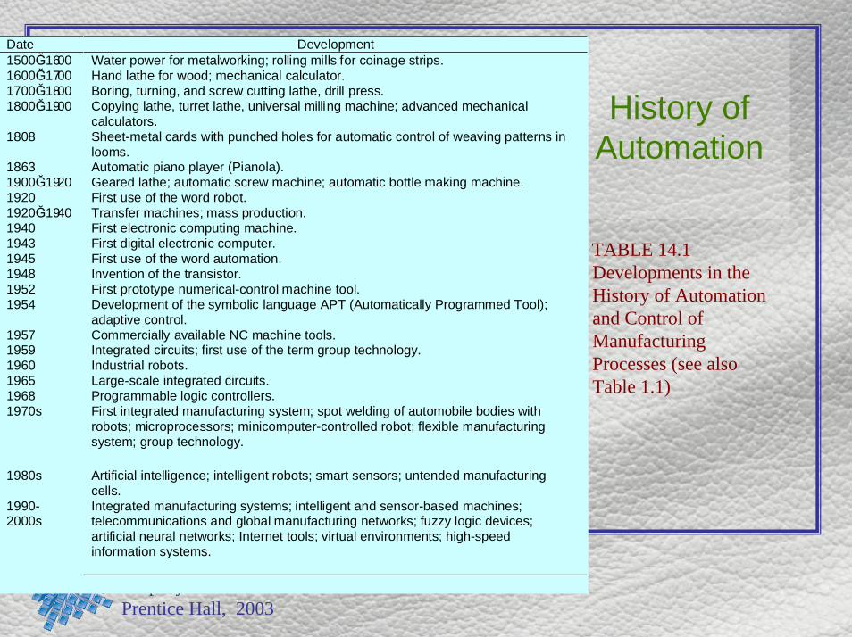
TABLE 14.1 Developments in the History of Automation and Control of Manufacturing Processes (see also Table 1.1)
Date Development1500Ğ1600 Water power for metalworking; rolling mills for coinage strips.1600Ğ1700 Hand lathe for wood; mechanical calculator.1700Ğ1800 Boring, turning, and screw cutting lathe, drill press.1800Ğ1900 Copying lathe, turret lathe, universal milling machine; advanced mechanical
calculators.1808 Sheet-metal cards with punched holes for automatic control of weaving patterns in
looms.1863 Automatic piano player (Pianola).1900Ğ1920 Geared lathe; automatic screw machine; automatic bottle making machine.1920 First use of the word robot.1920Ğ1940 Transfer machines; mass production.1940 First electronic computing machine.1943 First digital electronic computer.1945 First use of the word automation.1948 Invention of the transistor.1952 First prototype numerical-control machine tool.1954 Development of the symbolic language APT (Automatically Programmed Tool);
adaptive control.1957 Commercially available NC machine tools.1959 Integrated circuits; first use of the term group technology.1960 Industrial robots.1965 Large-scale integrated circuits.1968 Programmable logic controllers.1970s First integrated manufacturing system; spot welding of automobile bodies with
robots; microprocessors; minicomputer-controlled robot; flexible manufacturingsystem; group technology.
1980s Artificial intelligence; intelligent robots; smart sensors; untended manufacturingcells.
1990-2000s
Integrated manufacturing systems; intelligent and sensor-based machines;telecommunications and global manufacturing networks; fuzzy logic devices;artificial neural networks; Internet tools; virtual environments; high-speedinformation systems.

Manufacturing Processes for Engineering Materials, 4th ed.Kalpakjian • SchmidPrentice Hall, 2003
Type of Production and Volume
Type of production Number produced Typical productsExperimental or prototype 1-10 All typesPiece or small batch <5000 Aircraft, machine tools, diesBatch or high volume 5000-100,000 Trucks, agricultural machinery, jet engines,
diesel engines, orthopedic devicesMass production 100,000+ Automobiles, appliances, fasteners, bottles,
food and beverage containers
TABLE 14.2 Approximate annual volume of production.

Manufacturing Processes for Engineering Materials, 4th ed.Kalpakjian • SchmidPrentice Hall, 2003
Flexibility vs. Productivity
FIGURE 14.2 Flexibility and productivity of various manufacturing systems. Note the overlap between the systems, which is due to the various levels of automation and computer control that are possible in each group. See also Chapter 15 for more details. Source: U. Rembold et al., Computer Integrated Manufacturing and Engineering, Addison-Wesley, 1993.

Manufacturing Processes for Engineering Materials, 4th ed.Kalpakjian • SchmidPrentice Hall, 2003
Characteristics of Production Methods
FIGURE 14.3 General characteristics of three types of production methods: job shop, batch production, and mass production.

Manufacturing Processes for Engineering Materials, 4th ed.Kalpakjian • SchmidPrentice Hall, 2003
Transfer Mechanisms
FIGURE 14.4 Two types of transfer mechanisms: (a) straight, and (b) circular patterns.

Manufacturing Processes for Engineering Materials, 4th ed.Kalpakjian • SchmidPrentice Hall, 2003
Transfer Line Example FIGURE 14.5 A traditional transfer line for producing engine blocks and cylinder heads. Source: Ford Motor Company.

Manufacturing Processes for Engineering Materials, 4th ed.Kalpakjian • SchmidPrentice Hall, 2003
Measurement Approaches
FIGURE 14.6 Positions of drilled holes in a workpiece. Three methods of measurement are shown: (a) absolute dimensioning, referenced from one point at the lower left of the part; (b) incremental dimensioning, made sequentially from one hole to another; and (c) mixed dimensioning, a combination of both methods.

Manufacturing Processes for Engineering Materials, 4th ed.Kalpakjian • SchmidPrentice Hall, 2003
Numerical Control Machine
Tool
FIGURE 14.7 Schematic illustration of the major components of a numerical control machine tool.

Manufacturing Processes for Engineering Materials, 4th ed.Kalpakjian • SchmidPrentice Hall, 2003
Open and Closed Loop Control
FIGURE 14.8 Schematic illustration of the components of (a) an open-loop, and (b) a closed-loop control system for a numerical control machine. DAC means digital-to-analog converter.

Manufacturing Processes for Engineering Materials, 4th ed.Kalpakjian • SchmidPrentice Hall, 2003
Measurement of Linear Displacement
FIGURE 14.9 Direct measurement of the linear displacement of a machine-tool worktable. (b) and (c) Indirect measurement methods.

Manufacturing Processes for Engineering Materials, 4th ed.Kalpakjian • SchmidPrentice Hall, 2003
Path of Cutters in NC
FIGURE 14.10 Movement of tools in numerical control machining. (a) Point-to-point system: The drill bit drills a hole at position 1, is then retracted and moved to position 2, and so on. (b) Continuous path by a milling cutter. Note that the cutter path is compensated for by the cutter radius. This path can also compensate for cutter wear.

Manufacturing Processes for Engineering Materials, 4th ed.Kalpakjian • SchmidPrentice Hall, 2003
Types of Interpolation
FIGURE 14.11 Types of interpolation in numerical control: (a) linear; (b) continuous path approximated by incremental straight lines; and (c) circular.
Manufacturing Processes for Engineering Materials, 4th ed.Kalpakjian • SchmidPrentice Hall, 2003
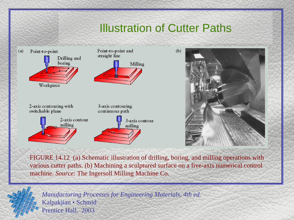
Illustration of Cutter Paths
FIGURE 14.12 (a) Schematic illustration of drilling, boring, and milling operations with various cutter paths. (b) Machining a sculptured surface on a five-axis numerical control machine. Source: The Ingersoll Milling Machine Co.

Manufacturing Processes for Engineering Materials, 4th ed.Kalpakjian • SchmidPrentice Hall, 2003
Adaptive Control in Turning
FIGURE 14.13 Schematic illustration of the application of adaptive control (AC) for a turning operation. The system monitors such parameters as cutting force, torque, and vibrations; if they are excessive, it modifies process variables such as feed and depth of cut to bring them back to acceptable levels.

Manufacturing Processes for Engineering Materials, 4th ed.Kalpakjian • SchmidPrentice Hall, 2003
Adaptive Control in Milling
FIGURE 14.14 An example of adaptive control in milling. As the depth of cut or the width of cut increases, the cutting forces and the torque increase. The system senses this increase and automatically reduces the feed to avoid excessive forces or tool breakage, in order to maintain cutting efficiency. Source: Y. Koren.

Manufacturing Processes for Engineering Materials, 4th ed.Kalpakjian • SchmidPrentice Hall, 2003
In-Process Inspection
FIGURE 14.15 In-process inspection of workpiece diameter in a turning operation. The system automatically adjusts the radial position of the cutting tool in order to produce the correct diameter.

Manufacturing Processes for Engineering Materials, 4th ed.Kalpakjian • SchmidPrentice Hall, 2003
Self-Guided Vehicle
FIGURE 14.16 A self-guided vehicle (Caterpillar Model SGC-M) carrying a machining pallet. The vehicle is aligned next to a stand on the floor. Instead of following a wire or stripe path on the factory floor, this vehicle calculates its own path and automatically corrects for any deviations. Source: Courtesy of Caterpillar Industrial, Inc.

Manufacturing Processes for Engineering Materials, 4th ed.Kalpakjian • SchmidPrentice Hall, 2003
Six-Axis Robot
FIGURE 14.17 (a) Schematic of a six-axis S-10 GMF robot. The payload at the wrist is 10 kg (22 lb.) and repeatability is ±0.2 mm (±0.008 in.). The robot has mechanical brakes on all its axes, which are coupled directly. (b) The work envelope of a robot, as viewed from the side. Source: GMFanuc Robotics Corporation.

Manufacturing Processes for Engineering Materials, 4th ed.Kalpakjian • SchmidPrentice Hall, 2003
Grippers for Robots
FIGURE 14.18 (a) Various devices and tools attached to end effectors to perform a variety of operations. (b) A system that compensates for misalignment during automated assembly. Source: ATI Industrial Automation.

Manufacturing Processes for Engineering Materials, 4th ed.Kalpakjian • SchmidPrentice Hall, 2003
Types of Industrial Robots
FIGURE 14.19 Four types of industrial robots: (a) Cartesian (rectilinear); (b) cylindrical; (c) spherical (polar); and (d) articulated (revolute, jointed, or anthropomorphic).

Manufacturing Processes for Engineering Materials, 4th ed.Kalpakjian • SchmidPrentice Hall, 2003
Work Envelopes for Robots
FIGURE 14.20 Work envelopes for three types of robots. The choice depends on the particular application. See also Fig. 14.17b.

Manufacturing Processes for Engineering Materials, 4th ed.Kalpakjian • SchmidPrentice Hall, 2003
Robot Applications
FIGURE 14.21 Spot welding automobile bodies with industrial robots. Source: Courtesy of Cincinnati Milacron, Inc.
FIGURE 14.22 Sealing joints of an automotive body with an industrial robot. Source: Courtesy of Cincinnati Milacron, Inc.

Manufacturing Processes for Engineering Materials, 4th ed.Kalpakjian • SchmidPrentice Hall, 2003
Automated Assembly
FIGURE 14.23 Automated assembly operations using industrial robots and circular and linear transfer lines.

Manufacturing Processes for Engineering Materials, 4th ed.Kalpakjian • SchmidPrentice Hall, 2003
Smart Tool Holder
FIGURE 14.24 A tool holder equipped with thrust force and torque sensors (smart tool holder), capable of continuously monitoring the cutting operation. Such tool holders are necessary for adaptive control of manufacturing operations. (See Section 14.5). Source: Cincinnati Milacron, Inc.

Manufacturing Processes for Engineering Materials, 4th ed.Kalpakjian • SchmidPrentice Hall, 2003
Gripper with Tactile Sensors
FIGURE 14.25 A robot gripper with tactile sensors. In spite of their capabilities, tactile sensors are now being used less frequently, because of their high cost and their low durability in industrial applications. Source: Courtesy of Lord Corporation.

Manufacturing Processes for Engineering Materials, 4th ed.Kalpakjian • SchmidPrentice Hall, 2003
Machine Vision Applications
FIGURE 14.26 Examples of machine vision applications. (a) In-line inspection of parts. (b) Identification of parts with various shapes, and inspection and rejection of defective parts. (c) Use of cameras to provide positional input to a robot relative to the workpiece. (d) Painting of parts that have different shapes by means of input from a camera. The system’s memory allows the robot to identify the particular shape to be painted and to proceed with the correct movements of a paint spray attached to the end effector.

Manufacturing Processes for Engineering Materials, 4th ed.Kalpakjian • SchmidPrentice Hall, 2003
Modular Workholding System
FIGURE 14.27 Typical components of a modular workholding system. Source: Carr Lane Manufacturing Co.

Manufacturing Processes for Engineering Materials, 4th ed.Kalpakjian • SchmidPrentice Hall, 2003
Adjustable-Force Clamping System
FIGURE 14.28 Schematic illustration of an adjustable force clamping system. The clamping force is sensed by the strain gage, and the system automatically adjusts this force. Source: P. K. Wright and D. A. Bourne, Manufacturing Intelligence, Reading, MA. Addison- Wesley, 1988.

Manufacturing Processes for Engineering Materials, 4th ed.Kalpakjian • SchmidPrentice Hall, 2003
Stages in Design-for-Assembly
Analysis
FIGURE 14.29 Stages in the design-for-assembly analysis. Source: Product Design for Assembly, 1989 edition, by G. Boothroyd and P. Dewhurst. Reproduced with permission.

Manufacturing Processes for Engineering Materials, 4th ed.Kalpakjian • SchmidPrentice Hall, 2003
Transfer Systems for Automated Assembly
FIGURE 14.30 Transfer systems for automated assembly: (a) rotary indexing machine; (b) in-line indexing machine. Source: G. Boothroyd.
Manufacturing Processes for Engineering Materials, 4th ed.Kalpakjian • SchmidPrentice Hall, 2003
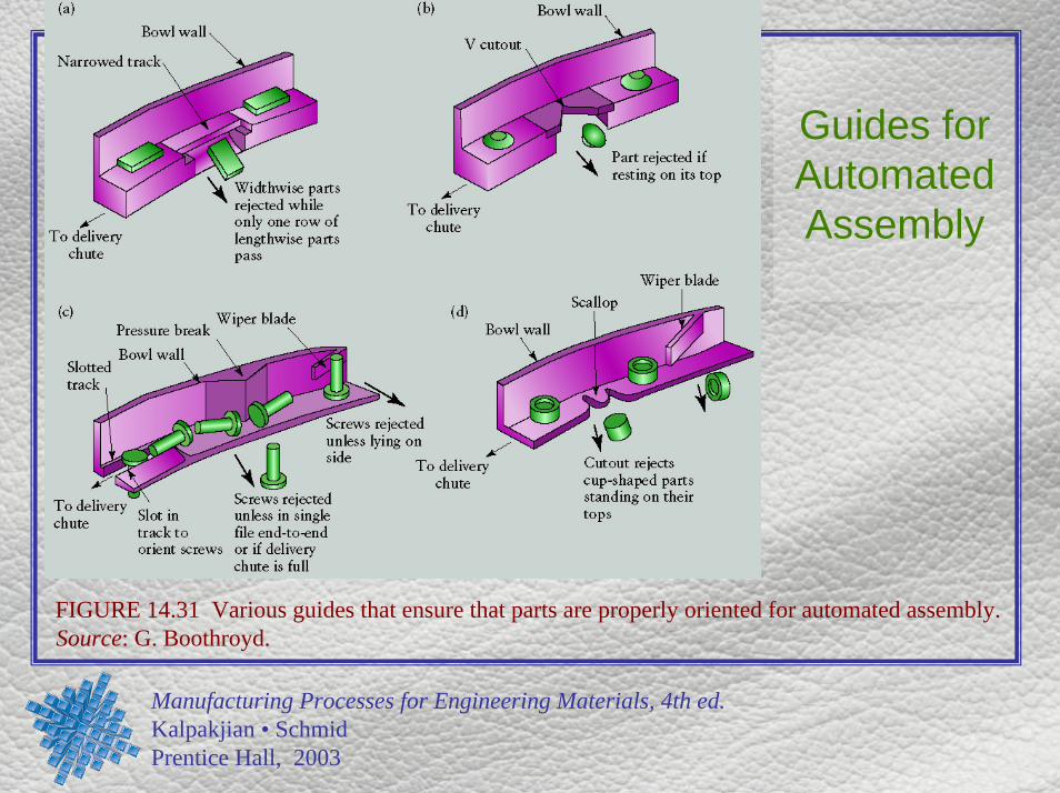
Guides for Automated Assembly
FIGURE 14.31 Various guides that ensure that parts are properly oriented for automated assembly. Source: G. Boothroyd.

Manufacturing Processes for Engineering Materials, 4th ed.Kalpakjian • SchmidPrentice Hall, 2003
Case Study Housing
FIGURE 14.32 Cast-iron housing and the machining operations required.

Manufacturing Processes for Engineering Materials, 4th ed.Kalpakjian • SchmidPrentice Hall, 2003
Modular Fixture Components
FIGURE 14.33 Modular components used to construct the fixture for CNC machining of the cast-iron housing depicted in Fig. 14.32.

Manufacturing Processes for Engineering Materials, 4th ed.Kalpakjian • SchmidPrentice Hall, 2003
Completed Modular Fixture
FIGURE 14.34 Completed modular fixture with cast-iron housing in place, as would be assembled for use ina machining center or CNC milling machine.