chapter 1 · study of the potato leafhopper in the lower atmosphere remotely piloted vehicles...
TRANSCRIPT

CHAPTER 1
BACKGROUND AND LITERATURE REVIEW:
THE USE OF UNMANNED AERIAL VEHICLES FOR AEROBIOLOGICAL
SAMPLING
INTRODUCTION
Agricultural biota (e.g., seeds, insects, pollen, plant pathogens, etc.) may be transported
over long distances in the atmosphere. It is important to understand the methods and
techniques of airborne transport so as to minimize the propagation of unwanted species in
crops that are important for human welfare. The long distance transport of biota takes
place primarily in the planetary boundary layer (PBL) of the atmosphere—the layer of
the atmosphere extending from approximately 50 m to 1 km above the surface of the
earth. Investigators have identified and characterized seeds (Shields et. al. 2006), insects
(Shields et al., 1999), and fungi in the PBL. One of the attractive techniques for
characterizing specific airborne species is to collect samples at different altitudes under a
variety of environmental conditions (e.g., day/night, temperature, humidity, and wind
conditions). One method that enables aerobiological sampling at various altitudes is the
use of remotely controlled aircraft designed to fly specific patterns and collect
aerobiological samples at an altitude of interest. Remotely piloted vehicles (RPV) have
been used for aerobiological sampling in agricultural ecosystems. This prior work, which
is summarized briefly later in this chapter, provides a foundation and motivation for the
current work. Agents that cause plant disease are thought to travel long distances in the
atmosphere and the transport mechanisms are not well understood.
- 1 -

STUDY OF THE POTATO LEAFHOPPER IN THE LOWER ATMOSPHERE
Remotely piloted vehicles (RPVs) have been used in the past to collect insects from the
lower atmosphere (Shields et al., 1999). The insect of interest was the potato leafhopper,
Empoasca fabae (Homoptera: Cicadellidae), which is a pest to many crops. This insect is
believed to travel long distances during migrating seasons in the PBL aided by wind to
get from one field to another. This is related to the work that we have done since they
used an RPV with a device that could be opened to sample at a desired altitude.
The RPV used for this study was the Senior Telemaster, which has a 2.4 m
wingspan and was powered by a 24 cc gasoline engine. The RPVs were outfitted with
nets mounted to the top of the wing surface to collect the potato leafhopper. The net was
closed during takeoff and landing and opened after reaching the desired altitude for
collection. To safely control the RPV, two RC receivers were installed so the RPV could
be landed under reduced control in the event of an RC link failure. In this setup, one
receiver controlled one side of the RPV (right aileron, right elevator) while the other
receiver controlled the other side of the RPV (left aileron, left elevator). Throttle was
controlled by one receiver and the rudder was controlled by the other receiver. The RPV
was equipped with sensors for measuring altitude, airspeed, and GPS position and this
data was transmitted to the ground where it could be monitored with a laptop computer.
The person monitoring the data could then give feedback to the pilot to better control the
RPV.
- 2 -

STUDY OF HORSEWEED IN THE PLANETARY BOUNDARY LAYER
Horseweed (Conyza Canadensis) is an agricultural weed that can reduce crop yield by as
much as 90%. Recently, horseweed has developed resistance to herbicides. Resistant
horseweed has the potential to spread through the atmosphere over long distances, and
colonize agricultural fields in new geographic locations. Shields et. al. (2006) used RPVs
to study the long distance transport of horseweed. They used an RPV monoplane with a
3-m wingspan powered by a 50 cc gasoline two-stroke engine. The RPV was designed
specifically for use in agricultural sampling on undeveloped runways. The RPV was
flown at full throttle at a speed of 26 m/s (96 km/h) at an altitude of 30 meters. The seed
collectors were mounted under each wing near the wing tips to minimize the effects of
the turbulent air from the propeller disturbing the sampled air. The sampling devices
were constructed using sail servos intended for small RC boats. Each RPV carried two
collectors that were capable of collecting two samples each, for a total of four samples
per flight. A standard 90-mm petri plate was modified by cutting the bottom of the plate
off and affixing a cloth mesh with 30-μm openings to the bottom of the plate. The
trapping surface was sprayed with a sticky adhesive just before the flight to retain any
seeds that struck the surface. The RPV used an onboard microcomputer to record and
transmit telemetry data which included altitude, airspeed, and GPS position. This data
was used to aid in controlling the aircrafts altitude by relay the information from a person
watching a computer to the pilot. A total of 17 flights were conducted over a three day
period in September 1998 in which 36 intact seeds were collected.
- 3 -

STUDY OF THE ABUNDACE OF THE FUNGAL PLANT PATHOGEN
GIBBERELLA ZEAE IN THE PLANETARY BOUNDARY LAYER
The most relevant research related to this work is the collection of Gibberella zeae in the
planetary boundary layer using RPVs (Maldonado-Ramirez et al., 2005). The RPV used
for this collection had a 2.4 m wingspan and used four spore-sampling devices. The
spore-sampling devices were made using sail RC servos intended to lift the sail on an RC
boat. They were used for their high torque capabilities. The servos had 90 mm diameter
petri plates attached to the end of wooden arms extending from the servo. The plates
would be closed during takeoff and landing to avoid contamination of the plates from
biota that was not at the desired altitude. Once the desired altitude was reached, the
collection plates would be opened by a RC switch from the ground. Each sampling plate
was exposed to approximately 8 m3 of air per minute with the RPV cruising at 20 m/s.
The sampling flights would last 15 minutes, exposing the media to approximately 120 m3
of air. A total of 12,858 viable spores of Gibberella zeae were collected during 158
flights over four consecutive years. The RPV was equipped with sensors for measuring
altitude, airspeed, and GPS position and this data was transmitted to the ground where it
could be monitored with a laptop computer. This data was transmitted to the ground
where it could be monitored with a laptop computer and then relayed to the pilot to better
control the RPV.
STUDY OF THE USE OF AUTONOMOUS SYSTEMS IN AGRICULTURE
A wide variety of autonomous systems has been applied to agricultural applications.
They include air vehicles used to spray agricultural fields with fungicides or herbicides,
- 4 -
to sample airborne contaminates, and to take photographs of agricultural fields.
Autonomous ground vehicles have been developed to harvest and to perform soil
preparation and sampling.
MicroPilot, one of the leading autopilot manufacturers in the world, developed a
UAV to monitor agricultural fields. A small hand-launched UAV was equipped with a
stripped down Pentax digital camera and called the system “CropCam.” The CropCam
system allowed farmers to monitor their own fields instead of hiring expensive
professional aerial photographers. The system would fly over the field and take GPS
stamped digital images before returning home. The system has an estimated cost of
$7,000 (Flight Global, 2006).
Autonomous systems for agricultural applications have not been limited to aerial
vehicles. Investigators at Virginia Tech have designed an autonomous broccoli
inspection and harvesting robot (Ramirez, 2006). The work focused on the development
of software and a computer vision system to locate the heads of broccoli using Hough
transforms of the lines on the stems and leaves. A co-occurrence matrix analysis
produced the location of the head and a statistical texture analysis was performed to
determine the maturity of the broccoli head. The work also included recommendations
on the type of vehicles that could be used to incorporate the developed software to
autonomously harvest the broccoli (Ramirez, 2006).
- 5 -

- 6 -

CHAPTER 2
DESIGN OF AN AUTONOMOUS UNMANNED AERIAL VEHICLE FOR
AEROBIOLOGICAL SAMPLING
INTRODUCTION
Previous studies have relied on radio controlled (RC) Unmanned Aerial Vehicles (UAVs)
also called RPVs to collect meaningful data in the atmosphere (Maldonado-Ramirez,
2005). There are some unavoidable problems with using RC for this purpose that include
poor positional accuracy, poor altitude accuracy, and pilot fatigue. It is very difficult for
any RC pilot to maintain a precise flight path at the same altitude for a given amount of
time, which leads to high variability in the flight path. The use of an autonomous UAV
can address nearly all the problems associated with RPVs. As part of the present study,
we designed autonomous unmanned aerial vehicle (UAV) systems to improve the
positional accuracy, altitude accuracy, and to reduce pilot fatigue when used for
aerobiological sampling.
PLATFORM FOR AN AUTONOMOUS UAV
The Senior Telemaster Almost Ready to Fly (STARF) (Hobby Lobby International, Inc.,
Brentwood, TN) was used as our aerial sampling platform. The STARF has a wingspan
of 94” with 1330 in2 of wing area and 320 in2 of rear stabilizer area. The stock STARF
construction plans suggest a 0.61 in3 engine. We used an O.S. 1.20 in3 engine (O.S.
Engines, Champaign, IL) that produces 3.1 hp at 9,000 rpm (Figure 2.1). A Master
Airscrew 15x8 inch K-Series propeller (Windsor Propeller Company, Rancho Cordova,
- 7 -

CA) was mounted to the engine. The larger engine was used to create more power to pull
the sampling plates through the air (since the plates, when open, create a considerable
amount of drag). The factory engine mounts required trimming to allow the slightly wider
engine. The servo tray was also modified to accommodate the autonomous system. The
stock servo tray, which houses the rudder, elevator, and throttle servos, was cut in half to
allow additional space inside the fuselage. Half of the servo tray was used to mount the
rudder and elevator servos (Figure 2.2). The throttle servo was mounted in the front of
the plane just behind the firewall to allow a pushrod to pass from its original intended
location. Custom servo mounts were glued in place and a micro servo (Futaba S3101,
Futaba, Champaign, IL) was installed to operate the throttle (Figure 2.3). A micro servo
was used here since there is limited space and there would be no heavy load on the
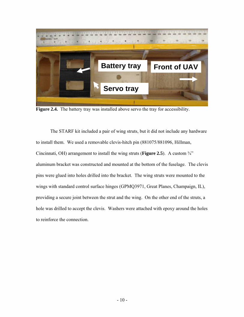
throttle servo at any time. The second half of the servo tray was modified for use as a
platform to mount batteries above the remaining half of the servo tray. This makes the
batteries easily accessible (Figure 2.4).
Figure 2.1. Senior Telemaster ARF with oversized 1.20AX engine.
- 8 -

Front of UAV
Servo tray
Figure 2.2. Top view showing how the servo tray was relocated to the back of the fuselage of the Senior Telemaster ARF.
Front of UAV
Figure 2.3. The throttle servo was relocated near the firewall on the Senior Telemaster ARF.
- 9 -
Servo tray
Battery tray Front of UAV
Figure 2.4. The battery tray was installed above servo the tray for accessibility.
The STARF kit included a pair of wing struts, but it did not include any hardware
to install them. We used a removable clevis-hitch pin (881075/881096, Hillman,
Cincinnati, OH) arrangement to install the wing struts (Figure 2.5). A custom ¾”
aluminum bracket was constructed and mounted at the bottom of the fuselage. The clevis
pins were glued into holes drilled into the bracket. The wing struts were mounted to the
wings with standard control surface hinges (GPMQ3971, Great Planes, Champaign, IL),
providing a secure joint between the strut and the wing. On the other end of the struts, a
hole was drilled to accept the clevis. Washers were attached with epoxy around the holes
to reinforce the connection.
- 10 -

Figure 2.5. Wing strut attachment method on the Senior Telemaster ARF.
AUTONOMOUS SYSTEM
Flight Controller. We used the MicroPilot MP2028g system (MicroPilot Inc., Stony
Mountain, Manitoba, Canada) as our autonomous flight controller. The MicroPilot
MP2028g system is lightweight (28 grams), has good functionality, and is relatively
affordable. The system permits the plane to navigate GPS waypoints through a desired
sampling area while providing the user with real-time dynamic control of flight
characteristics. The autopilot system is a printed circuit board that is equipped with 3-
axis gyros and accelerometers. These components provide inertial measurements to
allow control of the roll, pitch, and yaw of the UAV. A GPS unit attached to the board
receives satellite signals through the attached antenna. A static pressure sensor allows the
autopilot to measure relative altitude. The autopilot can also use GPS-based altitude data
to fly. Since this data is known to have a wide error band, it is not used for controlling
flight. A pitot tube pressure sensor is used to track the airspeed of the UAV. This sensor
- 11 -

was extended with tubing away from the fuselage to the leading edge of the wing on the
opposite side of the engine muffler to obtain accurate results.
A compass module (MP-COMP, MicroPilot Inc.) was added to the MicroPilot to
allow it to determine the true heading of the UAV. This heading is used in addition to the
GPS heading. This was particularly important for dealing with windy flying conditions.
The combination of GPS heading, compass heading, GPS speed, and airspeed allowed
the autopilot to calculate wind velocity and direction, ultimately resulting in more precise
control of the flight path. An ultrasonic above ground level (AGL) sensor (MP-AGL,
MicroPilot Inc.) was added to permit autonomous take-off and landing. This sensor uses
an ultrasonic transducer mounted on the bottom side of the fuselage to accurately
calculate distances to ground level at altitudes below five meters. The sensor is
connected to the autopilot via a shielded coaxial cable. An analog to digital converter
(ADC) (MP-ADC, MicroPilot Inc.) was added to allow for additional parameters to be
monitored such as additional battery voltages that are used to power other components.
All of the control surfaces on the aircraft were controlled by the autopilot. The
signal for the servos passed through a servo board, allowing the power supply to the
servo to be independent of the power supply to the MicroPilot. The plane can be
controlled manually via a 72MHz RC transmitter. The receiver (FUTJ7122, Futaba) on
the UAV has its signal passed through the autopilot board. Control is transferred to and
from the autopilot by a switch on the RC transmitter (FUTJ7122, Futaba). When in
manual mode, the signal is simply passed through the autopilot to the servo board and the
pilot on the ground had full control of all aspects of flight.
- 12 -

Control methods. MicroPilot used the Proportional, Integral, and Derivative (PID)
control loop gains to monitor and control flight performance. The gains can be adjusted
using ground control station software. The PID loops consisted of: (1) aileron from
desired roll, (2) elevator from desired pitch, (3) rudder from Y-accelerometer, (4) rudder
from heading, (5) throttle from speed, (6) throttle from glide slope, (7) pitch from
altitude, (8) pitch from AGL altitude, (9) pitch from airspeed, (10) roll from heading, and
(11) heading from cross track. All loops that control an actual control surface on the
UAV is updated at a rate of 30 Hz which includes loops (1), (2), (3), and (4). All other
control loops are updated at 5 Hz. The results from the inner loops (7, 8, 9, 10, and 11)
are used as inputs to the outer control loops that control the actual control surfaces of the
UAV. The gains were tuned to achieve the desired level of accuracy in flight (Dingus et
al., 2006).
Ground control station. The ground control station (GCS) consisted of a laptop
computer running MicroPilot Horizon (the ground control station software included with
the purchase of MicroPilot). The UAV communicated with the GCS via a 900MHz radio
modem, allowing real-time monitoring and control of nearly all aspects of flight. Flight
files containing GPS waypoints can be modified and uploaded during flight. The
Horizon software can be programmed to read any flight parameter or the output of the
Analog to Digital Converter (ADC) and display the information on the laptop in real
time. State values that were programmed to show on the graphical user interface (GUI)
are altitude, airspeed, GPS speed, and compass heading (Figure 2.6).
- 13 -

Figure 2.6. Screen shot of MicroPilot Horizon GCS software.
Electronics box. An electronics project box was used to house all the MicroPilot
components that needed to be installed in the UAV (Figure 2.7). This helped ensure that,
in the event of damaging the UAV, the expensive electronics would not be easily
damaged. A piece of plywood was cut to fit in the breadboard slots that are pre-formed
around the inside of the box. This piece was used as the mounting surface for the
autopilot board, compass, and ADC. The mounting orientation of the autopilot and the
compass were critical to optimal control operation in the autopilot. The autopilot was
mounted to the top of the plywood while the compass and the ADC were mounted to the
bottom of the plywood. Slots were cut in the plywood to allow all necessary wiring to be
connected between the components on opposite sides of the plywood. The servo board
was mounted to the back side of the box to allow for easy connection of the servo wires
without extra unnecessary wiring. Standard circuit board standoffs were glued to the box
- 14 -

to provide the desired spacing for the board. In order to do this, holes had to be cut into
the back of the box for the mounting screws and the servo output terminals. The
ultrasonic AGL was mounted in a similar fashion on the front of the box with its sensor
connection exiting at the top front of the box. Mounting in this orientation allowed the
sensor to be connected or disconnected without removal of the entire box. The lead for
the GPS antenna was mounted in a hole drilled in the back of the box to allow for easy
antenna removal. The required power was supplied through servo extensions passed
through a rubber grommet installed in the back of the box. This method allows the use
of standard RC power switches (SWH13, Futaba) to be mounted to the plane and then
plugged directly into the extensions on the back of the electronics box. For the current
design, four power switches were used: (1) autopilot, (2) radio modem, (3) servos, and
(4) spore-samplers. The autopilot and the radio modem use separate 11.1 volt lithium-ion
battery packs with 2200 mAh capacity (L18650-2200-3, Tenergy Corporation,
Sunnyvale, CA). The UAV control surface servos used a 4.8 volt Nickel-Cadmium
battery pack with 600 mAh capacity (NR-4J, Futaba) and the spore-samplers used a 4.8
volt Nickel Metal Hydride battery pack with 2000 mAh capacity (HCAM6320, Hobbico,
Champaign, IL). Separate batteries were used for safety so that if one system was not
working properly the other systems were not affected. This was done primarily because
the large spore-sampler servos have the potential to draw very high amounts of power
when they are opening and closing against the wind.
- 15 -

Figure 2.7. Electronics project box with components installed.
SPORE-SAMPLERS
The spore-sampling devices were designed with two large sail servos (HS-765HB, Hitec,
Poway, CA) mounted in a wooden frame and attached to the bottom of the wing. The
sail servos used are intended for use on an RC boat to lift the sails. Each servo controls
an arm that has a Petri dish lid permanently attached to it. While sampling, a Petri dish
bottom with the desired media is taped into the lid on the servo arm, allowing it to be
opened and closed. Another lid is permanently attached to a piece of plywood mounted
between the two servos. It extends forward to allow the Petri dishes on the arms to close
into the lids on the plywood to avoid exposing the plates during take-off and landing.
- 16 -

In previous work by Maldonado-Ramirez et al. (2005) spore-sampling devices
were mounted under the wing near the center of the wing chord and had servo arms that
were approximately eight inches long (Figure 2.8). The major problem encountered with
this design is the poor dynamic stability of the UAV when the sampling devices were
opened or closed. When the sampling devices were opened to begin sampling, the plane
would suddenly begin to pitch nose down since the devices introduced a large amount of
drag below the aerodynamic center of the UAV. To remedy this problem, the sampling
devices were redesigned to allow the Petri dishes to open on the leading edge of the wing
(Figure 2.9). This change essentially eliminated the pitching of the UAV when the
sampler devices were opened. The effective lifting force of the wing was reduced
slightly, since there was now turbulent air flowing over the airfoil directly behind the
sampling devices. On larger planes, this reduced lifting ability is typically not an issue
since the UAV is not carrying its maximum payload.
Figure 2.8. Design of previous spore-sampling devices (Maldonado-Ramirez et al., 2005).
- 17 -

Figure 2.9. New and improved design of spore-samplers on the autonomous Senior Telemaster ARF. The spore-samplers open (bottom) and close (top) on the leading edge of the wing.
The sampling devices are not permanently mounted to the wings of the UAV.
Rather, they are mounted using industrial strength Velcro to allow them to be removed
when needed. This mounting method also allows the sampler to detach upon a very hard
or crash landing, which helps to prevent the sampler from damaging the wing structure.
Power and signal is provided to the sampler servos by 36 inch servo extensions
(HCAM2726, Hobbico) routed inside the wing structure. Servo extensions were custom
installed inside the wing with the plug flush with the bottom of the wing. The extensions
were glued in place vertically to ensure that, if the sampling device was to become
detached from the wing, then the servo wire would be pulled out by the weight of the
sampler without ripping the extension through the structure of the wing. The four
sampling servos were controlled via one RC channel that was routed through a servo
synchronizer (MSA-10, Futaba) that allows the samplers to have an independent power
- 18 -

source from the rest of the UAV. Each servo can be adjusted independently to ensure the
servo is moving in the correct direction and stopping at the appropriate places in both
movement directions.
Two types of collection media have been used in our research: (1) Fusarium-
selective medium that allows only Fusarium spp. to grow (Figure 2.10) and (2) potato
dextrose agar which allows everything that is viable to grow (Figure 2.11).
Figure 2.10. Plates of Fusarium-selective medium showing white Fusarium colonies collected 100 m above the surface of the earth at Virginia Tech’s Kentland Farm.
- 19 -

Figure 2.11. Culturable fraction of an atmospheric microbial community collected 100m above the surface of the earth at Virginia Tech’s Kentland Farm. The plates contained a potato dextrose agar, a common medium for the cultivation of microbes.
- 20 -

- 21 -

CHAPTER 3
APPLICATION OF AN AUTONOMOUS UNMANNED AERIAL VEHICLE SYSTEM
FOR CONSISTENT AEROBIOLOGICAL SAMPLING
INTRODUCTION
Autonomous UAVs have the potential to extend the range of aerobiological sampling,
improve positional accuracy of sampling paths, and enable coordinated flight with
multiple aircraft at different altitudes. To determine the most appropriate sampling path
for aerobiological sampling, we explored a variety of different sampling patterns for our
autonomous UAVs including multiple GPS waypoints plotted over a variety of spatial
scales. It is important to define the parameters that may provide optimal performance of
autonomous UAVs in a variety of different sampling environments. Position and altitude
are two variables that are end results of the entire aircraft-building and gain-tuning
process. We explored five different aerobiological sampling patterns that were defined by
a series of GPS waypoints plotted over different spatial scales. The UAV was
programmed to maintain a target altitude of 100m while flying the following five
patterns: (1) single GPS waypoint, (2) two GPS waypoints, (3) three GPS waypoints, (4)
four GPS waypoints, and (5) four GPS waypoints in a figure-8 pattern. The specific
objectives of this study were to (1) determine the most appropriate sampling path for
aerobiological sampling above agricultural fields, and (2) determine the most effective
sampling pattern for maintaining a precise altitude during aerobiological sampling.
- 22 -

MATERIALS AND METHODS
Optimization of autonomous flight. The STARF was the UAV used to conduct
aerobiological sampling experiments at Virginia Tech’s Kentland Farm. We conducted a
series of preliminary flights to adjust gains for the STARF. During these flights, we
allowed the UAV to fly for 15 minutes under autopilot control without requiring RC
manual override. We optimized our gains and achieved stable and consistent flight
patterns with the sampling plates open since this would be when the UAV needed to
perform best. Aerobiological data was collected during individual 15-minute sampling
flights. We made small changes to the gains on the ground before each of the flight, flew
for a 15-minute sampling flight, and tuned the gains appropriately on the ground before
the next sampling flight. After 32 sampling flights, we arrived at an appropriate set of
gains for the UAV. We used this set of optimized gains for the next 25 sampling flights;
we did not make any further changes or adjustments to the autopilot during any of the
remaining flights.
Data collection during flight. The full dataset from the autopilot containing all UAV
states needed to conduct our analyses was downloaded directly from the autopilot after
each flight. Data was imported into MATLAB for calculations and plotting. Maintaining
an accurate altitude was considered to be the most important aspect of flight performance
and aerobiological sampling, therefore most of the time tuning the gains was spent to
reduce the variations in altitude during sampling. Also in this analysis the of the flight
patterns, the positional consistency of the patterns was visually inspected within flights
on a per loop basis and also compared between all different flights of the same pattern.
- 23 -

Autonomous patterns for aerobiological sampling. We chose five different GPS
waypoint patterns based on the need for a UAV to be capable of sampling above most
common size agricultural fields. These patterns were developed to keep the UAV within
line of sight of the pilot, in the event that the pilot needed to take RC control of the
aircraft during an emergency. The first pattern was a single GPS waypoint (Figure 3.1).
Instead of progressing through the GPS waypoint, the autopilot positioned the UAV into
a constant turn into the waypoint creating a circular pattern around the waypoint (Figure
3.1). The second pattern was two GPS waypoints separated by 325 meters (Figure 3.2).
The UAV flew an elliptical path around the two points, successfully passing through each
of the waypoints (Figure 3.2). The third pattern was three GPS waypoints arranged in an
equilateral triangle with each leg measuring 325 meters (Figure 3.3). The UAV also
successfully passed through each of the three waypoints (Figure 3.3). The fourth pattern
was a four GPS waypoint rectangle measuring 325 meters by 150 meters (Figure 3.4).
Due to the close proximity of the two waypoints separated by 150 meters, the autopilot
usually navigated an oval around the outside of the rectangle passing through the
waypoints at the end of the 325 meter leg (Figure 3.4). The fifth pattern was the same
four GPS waypoints as the rectangle pattern, but the navigation order was changed to
create a figure-8 sampling pattern (Figure 3.5). This pattern also utilized a different
navigation command to navigate the longer legs of the pattern. The MicroPilot ‘fromto’
command was used to force the autopilot to try to fly directly on the line connecting the
waypoints instead of just flying towards the next waypoint. The effects of this command
will be discussed in the results section.
- 24 -
(A) Flight 34 (B) Flight 35
(C) Flight 40 (D) Flight 41
(E) Flight 42 (F)
Figure 3.1. Autonomous flight patterns from for aerobiological sampling around a single GPS waypoint. Individual flight patterns (A-E), combined flight patterns (F).
- 25 -

(A) Flight 43 (B) Flight 48
(C) Flight 50 (D) Flight 51
(E) Flight52 (F)
Figure 3.2. Autonomous flight patterns from for aerobiological sampling around two GPS waypoints. Individual flight patterns (A-E), combined flight patterns (F).
- 26 -

(A) Flight 37 (B) Flight 38
(C) Flight 39 (D) Flight 58
(E) Flight 59 (F)
Figure 3.3. Autonomous flight patterns from for aerobiological sampling around three GPS waypoints. Individual flight patterns (A-E), combined flight patterns (F).
- 27 -

(A) Flight 36 (B) Flight 44
(C) Flight 46 (D) Flight 49
(E) Flight 53 (F)
Figure 3.4. Autonomous flight patterns from for aerobiological sampling around four GPS waypoints. Individual flight patterns (A-E), combined flight patterns (F).
- 28 -

(A) Flight 33 (B) Flight 54
(C) Flight 55 (D) Flight 56
(E) Flight 57 (F)
Figure 3.5. Autonomous flight patterns from for aerobiological sampling around four GPS waypoints in a figure-eight pattern. Individual flight patterns (A-E), combined flight patterns (F).
- 29 -

Comparison to remote-controlled flight. As a baseline for comparison, a flight was
conducted when only RC control was used. The autopilot was used to collect sensor data
rather than as flight controller. The single GPS waypoint pattern was flown. Based on
the collected data, that point appeared to give the most accurate pattern. The manually
piloted flight (Figure 3.6) was appears to be far less consistent than the autonomous
flights with respect to altitude hold and positional accuracy.
Figure 3.6. Inconsistent flight pattern from a remote-controlled aerobiological sampling flight around a single GPS waypoint. RESULTS/DISCUSSION
We conducted a total of 25 autonomous aerobiological sampling flights for five different
aerobiological sampling patterns. Table 3.1 contains flight data for each of these 25
flights. The table contains the flight day and time, media type, aerobiological data,
- 30 -

average altitude, altitude standard deviation, and description of the waypoint pattern used.
Each flight is plotted individually in Figures 3.1-3.5, a,b,c,d,e and as a combined overlay
plot in Figures 3.1-3.5, f).
Table 3.1. Flight data from autonomous sampling flights.
* datalog was not downloaded due to internal error of the autopilot
- 31 -

The single waypoint pattern exhibited no unpredicted behavior in any of the
flights. The altitude hold of this pattern resulted in standard deviations ranging from 1.6
to 2.8 meters. GPS noise, shown by sharp changes in path direction, created an artificial
inconsistency in the sampling pattern. This noise may be explained by fluctuations in
weather conditions, interference, or the position of tracked satellites.
The two GPS waypoint pattern showed some unreliability in the way that the
plane reversed direction from clockwise to counter-clockwise during flight. Reversing
direction during flight changed the angle at which the plane approached each waypoint
and therefore introduced a large positional inconsistency. This pattern also didn’t hold as
tight a tolerance on altitude because the plane had to make a hard bank at both ends of the
pattern. The three GPS waypoint pattern did fairly well on positional accuracy, but did
not maintain altitude for the same reasons as the two point pattern. The four GPS
waypoint pattern showed good positional accuracy and very good accuracy in
maintaining altitude with standard deviations ranging from 1.6 to 4.7 meters. The figure-
8 pattern did not have high positional accuracy, but appeared better than the two GPS
waypoint pattern. It was also not a strong performer in altitude hold due to the sharp
turns on both ends of the patterns.
Our UAV is capable of maintaining a very precise altitude for the duration of a
sampling flight (Figure 3.7). A range of ±5 meters around the target altitude was
obtained during many flights with standard deviations less than two meters. The RC
flight used as a comparison shows the differences between RC flight and autopilot flight.
The flight data is represented by Flight 45 (Table 3.1 and Figure 3.6). The standard
deviation for the RC flight was more than twice that of the autonomous flight for the
- 32 -

same flight pattern. This pattern was chosen since it appeared to be the best autonomous
pattern and was also the easiest to fly in RC mode. The pattern was easiest since the
flight path was a constant turn and it never required the UAV to be very far from the pilot
making it more controllable. From that point of view, it can be assumed that trying to fly
the other patterns RC would only result in limited positional accuracy and altitude hold.
Figure 3.7. Maintenance of a precise altitude during aerobiological sampling.
All of the GPS waypoint patterns performed well in holding altitude accuracy
relative to the accuracy of a standard RC RPV as used in the past (Shields, 2006). Two
of the patterns stand out as the most consistent sampling paths within flights and across
different flights. These two patterns are the single point pattern (Figure 3.1) and the four
point rectangular pattern (Figure 3.4). Both these patterns have very good positional
- 33 -

accuracy and an altitude range of ±5 meters around the target altitude with standard
deviations less than two meters on many flights. Both of these patterns are practical for
aerobiological sampling in agricultural fields.
- 34 -

- 35 -

CHAPTER 4
EXTENDED WORK WITH NEW AND ALTERNATIVE AUTONOMOUS
UNMANNED AERIAL VEHICLE SYSTEMS
THE SIG RASCAL 110” AS A NEW AEROBIOLOGICAL SAMPLING PLATFORM
Platform.
The Rascal 110” (SIG Manufacturing Co., Inc., Montezuma, IA) was chosen as
an alternative UAV platform to the Senior Telemaster due to its larger size and higher
payload capabilities (Figure 4.1). It was also a good choice since other collaborating
groups are also using this platform and therefore parts could be borrowed or interchanged
as needed.
Figure 4.1. Rascal 110” as a shown with samplers open (a) and samplers closed (b).
The Rascal 110” was built to accommodate two different engines. The first
engine used was O.S. 1.20 in3 (O.S. Engines), the same engine used on the Telemaster.
- 36 -
This engine was in the recommended size range for this aircraft but still performs very
well with the extra payload and drag of the spore-sampling devices. The second engine
used is the O.S. 1.60 in3 (O.S. Engines) which has 3.7 hp and is turning a 18x10 inch
Classic Series Master Airscrew propeller (Windsor Propeller Company). The larger
engine is more powerful but consumes a great deal more fuel. This engine can consume
24 oz of fuel in less than 14 minutes at full throttle. The factory 15 oz fuel tank was
replaced with a 24 oz fuel tank to allow for longer flight times. To accommodate this
larger tank, the factory tank mount had to be `h and custom firewall mounts installed on
which the tank could rest. It was desirable to move the servos out of the normal
mounting locations in the center of the UAV to free up more space for other components
and wiring. The throttle servo was moved forward and mounted on a custom bracket
(Figure 4.2). The factory throttle servo pushrod, which was a plastic tube-in-tube type,
was replaced with a solid metal pushrod to make the throttle response more precise. The
pull-pull rudder servo was not installed, but instead a standard pushrod and servo was
installed near the tail to actuate the rudder. This eliminated the servo wires of the pull-
pull design that normally ran the entire length of the fuselage. There is a factory cut slot
in the tail to allow the movement of the rudder servo. The window on the opposite side
of the muffler was replaced with a custom plywood camera mount. This enabled the
UAV to carry a digital camera to record video or to take high resolution digital images of
the fields below.
- 37 -

Figure 4.2. Relocated throttle servo to create space for autonomous unit and ensure consistent throttle response.
Electronics box. The same basic approach as used on the Telemaster was used to
incorporate the electronic components into the UAV. A standard project box was
modified to house the autopilot, compass, GPS receiver, and servo board (Figure 4.3).
Holes were cut in the front of the box to mount the GPS antenna cable and the autopilot
communications port. On the back of the box, holes were cut to mount two power
connection cables and a larger hole was cut for the servo board to allow the servo signal
wires to be plugged into the appropriate terminals. The pitot tube was also routed
through the back of the box via a 90º vacuum elbow.
- 38 -

Figure 4.3. Electronics box for Rascal 110”.
Redundant control via the RxMUX. An additional safety feature was added to the
Rascal UAV that increases safety for humans and for the expensive equipment onboard
the UAV. The RxMUX (Reactive Technologies, Merrimack, NH) allows the addition of
a second RC receiver to be added to the UAV for redundant control from the ground.
The RxMUX is a signal multiplexer that takes inputs from two RC receivers and outputs
one signal to control the servos of the UAV (Figure 4.4) (Dingus et al, 2007). In this
case, the primary source of control is the autopilot, which can be controlled by its own
RC receiver. The secondary source of control is the backup RC receiver on a different
channel from the autopilot. The receiver that passes through the autopilot has a channel
that allows the safety pilot to reclaim control at any time with the flip of a switch on the
- 39 -

transmitter. The RxMUX also allows one channel of the input to control which input
source is controlling the servos. With this setup, the UAV can be operated independently
with either transmitter. In other words, only one of the two transmitters is needed to fly
the UAV at any given time. If only the autopilot transmitter is used, the pilot is able to
pass control back and forth to the autopilot. If only the backup transmitter is used, the
UAV can only be flown in RC controlled mode. But with the combination of the two,
two pilots can be watching the UAV during flight where both have the ability to take
control from the autopilot if something goes wrong. If the secondary transmitter takes
control of the UAV, then the primary transmitter and the autopilot can not take control
back at any time. The secondary backup pilot has to give control back the primary
transmitter or autopilot. This system allows the pilot to be in two different locations with
two different views of the UAV and whoever has the best view of the UAV can have
control. The only time that communication between the two pilots is needed is when the
secondary backup transmitter gives control back the primary transmitter.
- 40 -

Figure 4.4. The RxMUX allows for redundant RC control from the ground for safety.
SPORE-SAMPLERS
The same spore samplers that were described for the Senior Telemaster were used on the
Rascal. The samplers could be interchanged between UAVs freely since they are made
exactly the same way. A newly designed sampler was created to allow for more flexible
data collection. The new design uses smaller 60 mm petri plates with a total of six per
sampler (Figure 4.5). The only modifications the old sampler design were changing the
arm the plates attached to and the piece of plywood in the center of the samplers that the
plates close onto. Each arm was created to hold three plates in a straight line. With this
- 41 -

design, multiple media types can be used in one flight. This allows comparison of
different samples taken at exactly the same time.
Figure 4.5. Redesigned sampling devices allow for greater flexibility of media used.
- 42 -

- 43 -

CHAPTER 5
CONTRIBUTIONS, RECOMMENDATIONS, AND FUTURE WORK
CONTRIBUTIONS
We believe that our work using UAVs for aerobiological sampling has resulted in several
research milestones. We completed the first autonomous sampling flight. We believe
this has produced the most consistent aerobiological sampling path recorded and the most
consistent aerobiological sampling height. We also completed the first autonomous
sampling using 12 individual sampling plates in one sampling flight. We also believe our
sampling has resulted in the first examination of entire Fusarium populations in the
atmosphere, 100 m above the ground. Previous work was only concerned with a single
Fusarium species, Gibberella zeae (Maldonado-Ramirez et al., 2005). We also are the
first to examine entire atmospheric microbial communities.
RECOMMENDATIONS
Coordinated sampling with the Piccolo autonomous system. A recommendation to
further extend the capabilities of our UAVs is to use the Piccolo (Cloud Cap Technology,
Hood River, OR) family of autopilots. With Piccolo autopilots the UAVs could
relatively easily be programmed to fly coordinated flight paths. This is an extension of
the simultaneous flights mentioned previously where the plane are just in the air at the
same time flying the same predefined waypoints. With Piccolo, a small amount of user
written-code could make one UAV a master and any number of other UAVs slaves
following the commands of the master resulting in UAVs not only flying the same path
- 44 -

but flying the same path at same positional location at the same time to result in truly
coordinated flight. The concept of this coordinated vehicle communication has already
been proven at Virginia Tech by coordination of an unmanned ground vehicle (UGV) and
a UAV where the UGV was the master and the UAV was the slave monitoring the UGV
from above.
FUTURE WORK
Night-time flight. There are a few additional objective planned for our UAVs to make
them even more functional. We will add navigation lights to enable flights at night. The
most appealing light source that we have located is the RC Airplane Beacon (Rod-N-
Bobb’s, Eau Claire, WI) which is a complete lightweight unit that provides red, green,
and yellow lights for the left wing, right wing, and tail, respectively. Many interesting
questions can be answered with nighttime flights. With this capability, we will be able to
sample the atmosphere at anytime during the day or night. For example, we could
sample for a 24 hour period every hour. To our knowledge, this has never been done
before. Since the system is autonomous, the only part of the flight that he pilot has to do
is the takeoff and landing which makes the RC pilot’s tasks far less stressful.
Simultaneous UAVs for aerobiological sampling at multiple altitudes. As soon as the
Racal 110” platform is fully developed and navigating precisely, we will use two or more
UAVs in the air at one time at different altitudes. This will require multiple pilots
preparing multiple planes on the ground. We will takeoff one plane and climb to the
higher of the desired altitudes. The second plane will then takeoff and climb to the lower
- 45 -

of the desired altitudes. At that time, we will set both planes into in autonomous mode
where they will enter the desired flight path. This can also answer some interesting
questions having two precisely controlled UAVs navigating the atmosphere collecting
samples at different altitudes at exactly the same time.
- 46 -

- 47 -
LITERATURE CITED
Dingus, B., Hoppe, L., Lee, J., Misyak, N., Pape, D., Ryan, J., Schivikas, M., Shake, S., Veraa, C., and Reinholtz, C. 2006. Development of a fixed-wing autonomous aerial vehicle at Virginia Tech. Dingus, B., Schmale, D.G., Reinholtz, C.F., 2007. Development of an autonomous unmanned aerial vehicle (UAV) for aerobiological sampling. APS Potomac Division Meeting. Flight Global, MicroPilot unveils own agricultural UAV to help shape civil market evolution. November 2006. Online. Internet. April 2007. <http://www.flightglobal.com/articles/2006/09/11/208933/micropilot-unveils-own-agricultural-uav-to-help-shape-civil-market.html> Maldonado-Ramirez, S.L., Schmale, D.G., Shields, E.J., and Bergstrom, G.C. 2005. The relative abundance of viable spores of Gibberella zeae in the planetary boundary layer suggests the role of long- distance transport in regional epidemics of Fusarium head blight. Agric. For. Meteorol. 132: 20-27. Ramirez, Rachael A., 2006. Computer Vision Based Analysis of Broccoli for Application in a Selective Autonomous Harvester. Shields, E.J., Testa, A.M., 1999. Fall migratory flight initiation of the potato leafhopper, Empoasca fabae (Homoptera: Cicadellidae): observations in the lower atmosphere using remote piloted vehicles. Agric. Forest Meteorol. 97, 317–330. Shields, E. J., J. T. Dauer, M. J. Van Gessel, and G. Neumann. 2006. Horseweed (Conyza Canadensis) seeds collected in the planetary boundary layer. Weed Sci. 54:1063-1067.
- 48 -