chapter 1: scenario 1: fallback procedure when … · web viewtask 6: switch activity from side a...
TRANSCRIPT

Document Number EDCS-441247 Revision 25.0
Cisco BTS 10200 Softswitch Software Upgrade for Release3.5.4.Vxx to 4.5.0.Vxx
July 2, 2006
Corporate HeadquartersCisco Systems, Inc.170 West Tasman DriveSan Jose, CA 95134-1706USAhttp://www.cisco.comTel: 408 526-4000
800 553-NETS (6387)Fax: 408 526-4100

THE SPECIFICATIONS AND INFORMATION REGARDING THE PRODUCTS IN THIS MANUAL ARE SUBJECT TO CHANGE WITHOUT NOTICE. ALL STATEMENTS, INFORMATION, AND RECOMMENDATIONS IN THIS MANUAL ARE BELIEVED TO BE ACCURATE BUT ARE PRESENTED WITHOUT WARRANTY OF ANY KIND, EXPRESS OR IMPLIED. USERS MUST TAKE FULL RESPONSIBILITY FOR THEIR APPLICATION OF ANY PRODUCTS.
THE SOFTWARE LICENSE AND LIMITED WARRANTY FOR THE ACCOMPANYING PRODUCT ARE SET FORTH IN THE INFORMATION PACKET THAT SHIPPED WITH THE PRODUCT AND ARE INCORPORATED HEREIN BY THIS REFERENCE. IF YOU ARE UNABLE TO LOCATE THE SOFTWARE LICENSE OR LIMITED WARRANTY, CONTACT YOUR CISCO REPRESENTATIVE FOR A COPY.
The Cisco implementation of TCP header compression is an adaptation of a program developed by the University of California, Berkeley (UCB) as part of UCB’s public domain version of the UNIX operating system. All rights reserved. Copyright © 1981, Regents of the University of California.
NOTWITHSTANDING ANY OTHER WARRANTY HEREIN, ALL DOCUMENT FILES AND SOFTWARE OF THESE SUPPLIERS ARE PROVIDED “AS IS” WITH ALL FAULTS. CISCO AND THE ABOVE-NAMED SUPPLIERS DISCLAIM ALL WARRANTIES, EXPRESSED OR IMPLIED, INCLUDING, WITHOUT LIMITATION, THOSE OF MERCHANTABILITY, FITNESS FOR A PARTICULAR PURPOSE AND NONINFRINGEMENT OR ARISING FROM A COURSE OF DEALING, USAGE, OR TRADE PRACTICE.
IN NO EVENT SHALL CISCO OR ITS SUPPLIERS BE LIABLE FOR ANY INDIRECT, SPECIAL, CONSEQUENTIAL, OR INCIDENTAL DAMAGES, INCLUDING, WITHOUT LIMITATION, LOST PROFITS OR LOSS OR DAMAGE TO DATA ARISING OUT OF THE USE OR INABILITY TO USE THIS MANUAL, EVEN IF CISCO OR ITS SUPPLIERS HAVE BEEN ADVISED OF THE POSSIBILITY OF SUCH DAMAGES.
CCIP, CCSP, the Cisco Arrow logo, the Cisco Powered Network mark, the Cisco Systems Verified logo, Cisco Unity, Follow Me Browsing, FormShare, iQ Breakthrough, iQ FastTrack, the iQ Logo, iQ Net Readiness Scorecard, Networking Academy, ScriptShare, SMARTnet, TransPath, and Voice LAN are trademarks of Cisco Systems, Inc.; Changing the Way We Work, Live, Play, and Learn, The Fastest Way to Increase Your Internet Quotient, and iQuick Study are service marks of Cisco Systems, Inc.; and Aironet, ASIST, BPX, Catalyst, CCDA, CCDP, CCIE, CCNA, CCNP, Cisco, the Cisco Certified Internetwork Expert logo, Cisco IOS, the Cisco IOS logo, Cisco Press, Cisco Systems, Cisco Systems Capital, the Cisco Systems logo, Empowering the Internet Generation, Enterprise/Solver, EtherChannel, EtherSwitch, Fast Step, GigaStack, Internet Quotient, IOS, IP/TV, iQ Expertise, LightStream, MGX, MICA, the Networkers logo, Network Registrar, Packet, PIX, Post-Routing, Pre-Routing, RateMUX, Registrar, SlideCast, StrataView Plus, Stratm, SwitchProbe, TeleRouter, and VCO are registered trademarks of Cisco Systems, Inc. and/or its affiliates in the U.S. and certain other countries.
All other trademarks mentioned in this document or Web site are the property of their respective owners. The use of the word partner does not imply a partnership relationship between Cisco and any other company. (0301R)
Cisco BTS 10200 Softswitch Software Upgrade
Copyright © 2005, Cisco Systems, Inc.
All rights reserved.
Cisco BTS 10200 Softswitch Software UpgradePage 2

Revision History Date Versio
nDescription
4/6/2005 1.0 Initial Version4/15/2005 2.0 Removed “forced“ from control commands once the system is
in 4.5.05/5/2005 3.0 Corrected typo in Appendix T.5/17/2005 4.0 Incorporated comments resulted from the document review5/26/3005 5.0 Moved the announcement and new feature provisioning from
mid-upgrade to prost-upgrade. Also, removed steps where SS7 CICs are being controlled out before making 4.5.0 active and steps for controlling them into service after 4.5.0 becoming active.
6/6/2005 6.0 Revised Chapter 7, Task 3 for better instructions and Chapter 7, task 4 for reusing the old domain name with logical IPs
6/9/2005 7.0 Added steps in Chapter 2 to prepare ITP. Removed task 3 and 4 in Chapter 7.
6/27/2005 8.0 Moved Chapter 6, Task 1 to Task 3.6/28/2005 This procedure used 3.5.4.V01 and 4.5.0 plus patches for
verification.6/29/2005 9.0 Remove redundant task 8 to sync db usage in Chapter 77/1/2005 10.0 Added pre-check for table SLE7/6/2005 11.0 Corrected Appendix R step 3. Change trunk-termination to
trunk-grp7/7/2005 12.0 Added more details to the SLE table check.7/18/2005 13.0 Added Task 7 and Task 8 in Appendix H to handle BDMS PC
CHP version mismatches7/25/2005 14.0 Added new comments in the Chapter 2: Each customer must
purchase 8 disks with matching disk size to the existing system that is to be upgraded.
7/28/2005 15.0 Add new parameters introduced in opticall.cfg in the 450 Q17 load:
CAxxx_LAF_PARAMETER FSPTCxxx_LAF_PARAMETER
FSAINxxx_LAF_PARAMETER
EMS_LAF_PARAMETER
Cisco BTS 10200 Softswitch Software UpgradePage 3

BDMS_LAF_PARAMETER
8/19/2005 16.0 Added appendix X to enable disk mirroring after completing upgrade
11/10/2005
17.0 Revised Appendix X disk mirroring steps.
11/28/2005
18.0 Corrected typo on Page 32, Task 7, Step 3 and added Task 9 in Chapter 4. Added Task 1 in Chapter 2.
12/06/2005
19.0 Added an “exit” step in Chapter 8, Task 6, Step 3. And added Task 2 in Chapter 6 for checking ntp.conf file peer information. Modified disk mirroring steps to complete the process One side at a time.
1/6/2006 20.0 Added pre-upgrade step to make sure there are terminations associated with ss7 trunk groups.
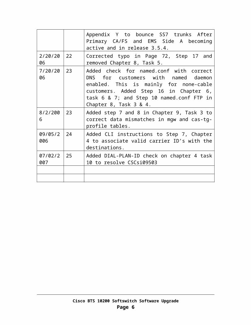
1/30/2006 21 Correct the error in the SQL statement for pre-checking the SS7 trunk groups. Added Appendix Y to bounce SS7 trunks After Primary CA/FS and EMS Side A becoming active and in release 3.5.4.
2/20/2006 22 Corrected typo in Page 72, Step 17 and removed Chapter 8, Task 5.
7/20/2006 23 Added check for named.conf with correct DNS for customers with named daemon enabled. This is mainly for none-cable customers. Added Step 16 in Chapter 6, task 6 & 7; and Step 10 named.conf FTP in Chapter 8, Task 3 & 4.
8/2/2006 23 Added step 7 and 8 in Chapter 9, Task 3 to correct data mismatches in mgw and cas-tg-profile tables.
09/05/2006
24 Added CLI instructions to Step 7, Chapter 4 to associate valid carrier ID’s with the destinations.
07/02/2007
25 Added DIAL-PLAN-ID check on chapter 4 task 10 to resolve CSCsi09503
Cisco BTS 10200 Softswitch Software UpgradePage 4

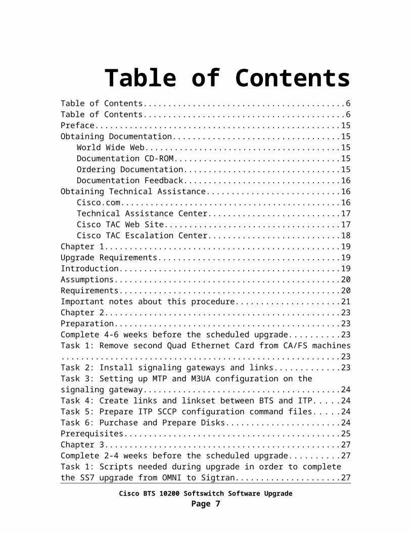
Table of ContentsTable of Contents.................................................................................................................6Table of Contents.................................................................................................................6Preface...............................................................................................................................15Obtaining Documentation..................................................................................................15
World Wide Web.......................................................................................................15Documentation CD-ROM..........................................................................................15Ordering Documentation...........................................................................................15Documentation Feedback..........................................................................................16
Obtaining Technical Assistance........................................................................................16Cisco.com..................................................................................................................16Technical Assistance Center......................................................................................17Cisco TAC Web Site.................................................................................................17Cisco TAC Escalation Center....................................................................................18
Chapter 1............................................................................................................................19Upgrade Requirements......................................................................................................19Introduction........................................................................................................................19Assumptions......................................................................................................................20Requirements.....................................................................................................................20Important notes about this procedure................................................................................21Chapter 2............................................................................................................................23Preparation.........................................................................................................................23Complete 4-6 weeks before the scheduled upgrade..........................................................23Task 1: Remove second Quad Ethernet Card from CA/FS machines...............................23Task 2: Install signaling gateways and links.....................................................................23Task 3: Setting up MTP and M3UA configuration on the signaling gateway..................24Task 4: Create links and linkset between BTS and ITP....................................................24Task 5: Prepare ITP SCCP configuration command files.................................................24Task 6: Purchase and Prepare Disks..................................................................................24Prerequisites.......................................................................................................................25Chapter 3............................................................................................................................27Complete 2-4 weeks before the scheduled upgrade..........................................................27Task 1: Scripts needed during upgrade in order to complete the SS7 upgrade from OMNI to Sigtran............................................................................................................................27Task 2: Scripts for post-upgrade new feature activation...................................................28Chapter 4............................................................................................................................29Complete one week before the scheduled upgrade............................................................29Task 1: Add new domain names to DNS...........................................................................29Task 2: Pre-construct opticall.cfg for the system to be upgraded to 4.5.0 release............31Task 3: Check RUDP_BACKHAUL_SESSION port number assignment......................32From Active EMS..............................................................................................................32Task 4: Check mlhg_terminal table...................................................................................33From Active EMS..............................................................................................................33
Cisco BTS 10200 Softswitch Software UpgradePage 5
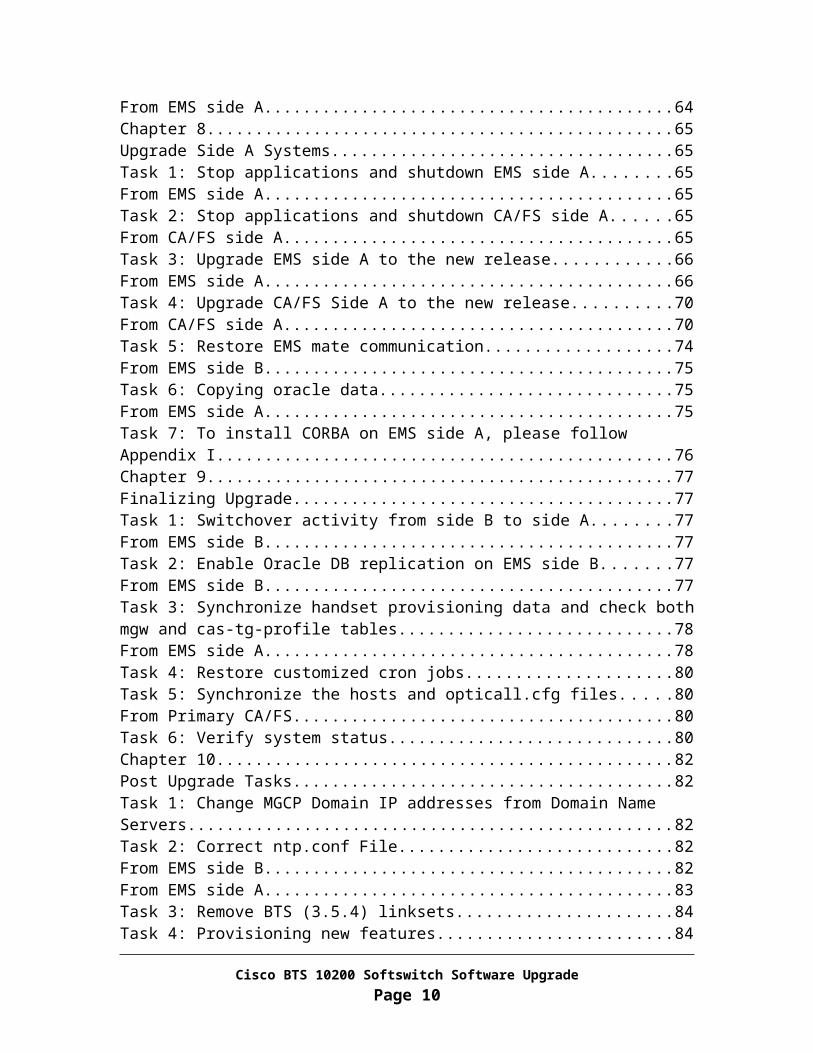
Task 5: Check mgw table..................................................................................................33From Active EMS..............................................................................................................33Task 6: Check Termination table.......................................................................................34From Active EMS..............................................................................................................34Task 7: Check Destination table........................................................................................34From Active EMS..............................................................................................................34Task 8: Check SLE table...................................................................................................35From Active EMS..............................................................................................................35Task 9: Check Trunk_grp table.........................................................................................35From Active EMS..............................................................................................................35Task 10: Check DIAL_PLAN_ID Table...........................................................................36From Active EMS..............................................................................................................36Task 11: Check call-agent-profile CDB generation Flag..................................................36From Active EMS..............................................................................................................36Task 12: Change SS7-CIC table for SS7 Upgrade............................................................37Task 13: Save customized cron jobs..................................................................................37Chapter 5............................................................................................................................38Prepare System for Upgrade..............................................................................................38Task 1: Change MGCP Domain IP addresses from Domain Name servers......................38Task 2: Verify System Status............................................................................................38Task 3: Check required billing information.......................................................................39From EMS Side A.............................................................................................................39Task 4: Backup Billing DB................................................................................................39From EMS Side A.............................................................................................................40Task 5: Backup user account.............................................................................................40From EMS Side A.............................................................................................................40Chapter 6............................................................................................................................41Upgrade Side B Systems...................................................................................................41Task 1: Disable Oracle DB replication..............................................................................41From EMS side A..............................................................................................................41From EMS side A..............................................................................................................41Task 2: Force side A systems to active..............................................................................42From Active EMS Side B..................................................................................................42Task 3: Inhibit EMS mate communication........................................................................42From EMS side A..............................................................................................................43Task 4: Stop applications and shutdown EMS side B.......................................................43From EMS side B..............................................................................................................43Task 5: Stop applications and shutdown CA/FS side B....................................................43From CA/FS side B...........................................................................................................44Task 6: Upgrade EMS side B to the new release...............................................................44From EMS side B..............................................................................................................45Task 7: Upgrade CA/FS Side B to the new release...........................................................50From CA/FS side B...........................................................................................................50Task 8: Migrate oracle data...............................................................................................56From EMS side B..............................................................................................................56Task 9: Restore billing address and billing alarm.............................................................57
Cisco BTS 10200 Softswitch Software UpgradePage 6
From EMS side B..............................................................................................................57Task 10: To install CORBA on EMS side B, please follow Appendix I...........................58Chapter 7............................................................................................................................59Prepare Side A Systems for Upgrade................................................................................59Task 1: Control SS7 trunk groups out of service on release 3.5.4.....................................59From EMS side A..............................................................................................................59Task 2: Control SS7 links out of service...........................................................................59From CA/FS side A...........................................................................................................60Task 3: Force side A systems to standby...........................................................................60From EMS side A..............................................................................................................60Task 4: Provision 4.5.0 SS7 configuration........................................................................61From EMS side B..............................................................................................................61Task 5: Control SS7 trunk groups in service.....................................................................61From EMS side B..............................................................................................................62Task 6: Sync Data from EMS side B to CA/FS side B.....................................................62From EMS side B..............................................................................................................62Task 7: Validate release 4.5.0 software operation.............................................................63From EMS side B..............................................................................................................63From EMS side A..............................................................................................................64Chapter 8............................................................................................................................65Upgrade Side A Systems...................................................................................................65Task 1: Stop applications and shutdown EMS side A.......................................................65From EMS side A..............................................................................................................65Task 2: Stop applications and shutdown CA/FS side A....................................................65From CA/FS side A...........................................................................................................65Task 3: Upgrade EMS side A to the new release..............................................................66From EMS side A..............................................................................................................66Task 4: Upgrade CA/FS Side A to the new release...........................................................70From CA/FS side A...........................................................................................................70Task 5: Restore EMS mate communication......................................................................74From EMS side B..............................................................................................................75Task 6: Copying oracle data..............................................................................................75From EMS side A..............................................................................................................75Task 7: To install CORBA on EMS side A, please follow Appendix I............................76Chapter 9............................................................................................................................77Finalizing Upgrade............................................................................................................77Task 1: Switchover activity from side B to side A............................................................77From EMS side B..............................................................................................................77Task 2: Enable Oracle DB replication on EMS side B......................................................77From EMS side B..............................................................................................................77Task 3: Synchronize handset provisioning data and check both mgw and cas-tg-profile tables..................................................................................................................................78From EMS side A..............................................................................................................78Task 4: Restore customized cron jobs...............................................................................80Task 5: Synchronize the hosts and opticall.cfg files..........................................................80From Primary CA/FS.........................................................................................................80
Cisco BTS 10200 Softswitch Software UpgradePage 7

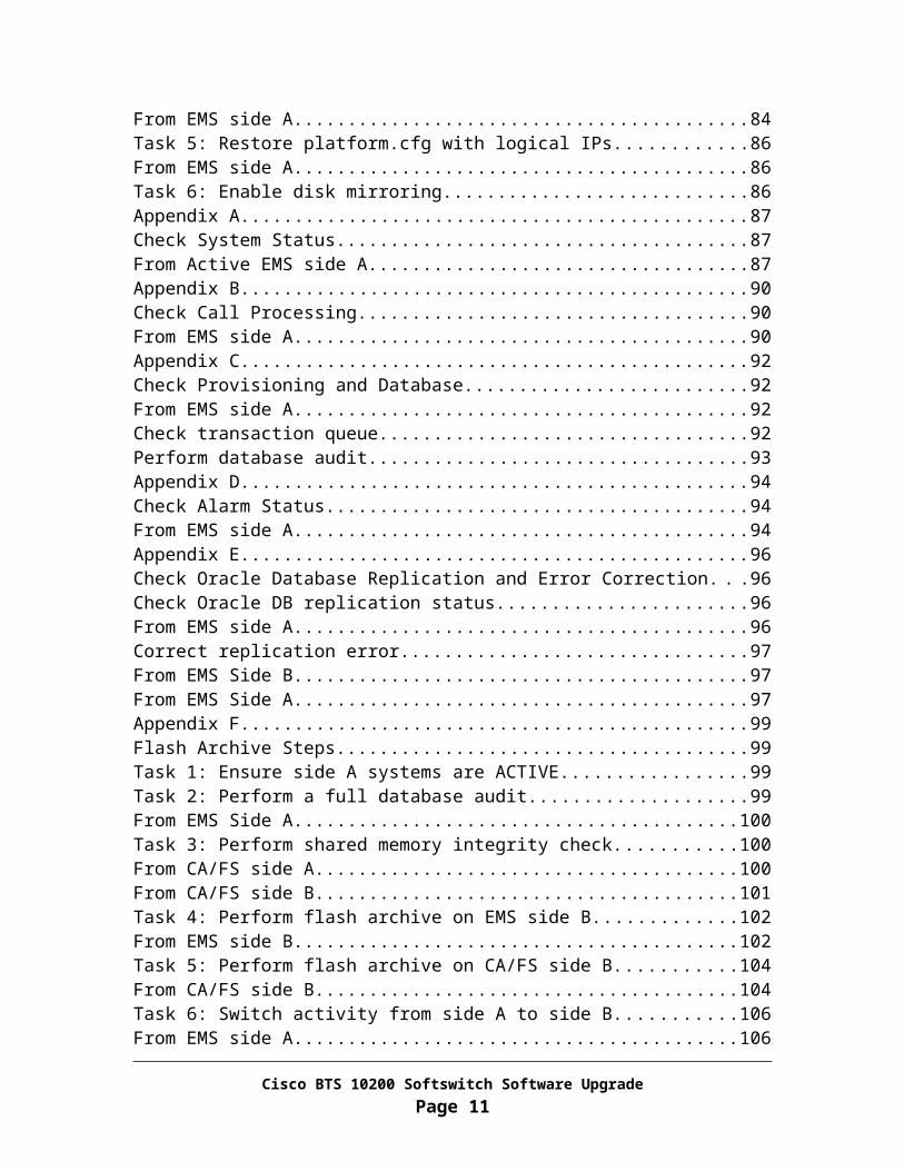
Task 6: Verify system status..............................................................................................80Chapter 10..........................................................................................................................82Post Upgrade Tasks...........................................................................................................82Task 1: Change MGCP Domain IP addresses from Domain Name Servers.....................82Task 2: Correct ntp.conf File.............................................................................................82From EMS side B..............................................................................................................82From EMS side A..............................................................................................................83Task 3: Remove BTS (3.5.4) linksets................................................................................84Task 4: Provisioning new features.....................................................................................84From EMS side A..............................................................................................................84Task 5: Restore platform.cfg with logical IPs...................................................................86From EMS side A..............................................................................................................86Task 6: Enable disk mirroring...........................................................................................86Appendix A........................................................................................................................87Check System Status..........................................................................................................87From Active EMS side A..................................................................................................87Appendix B........................................................................................................................90Check Call Processing.......................................................................................................90From EMS side A..............................................................................................................90Appendix C........................................................................................................................92Check Provisioning and Database.....................................................................................92From EMS side A..............................................................................................................92Check transaction queue....................................................................................................92Perform database audit......................................................................................................93Appendix D........................................................................................................................94Check Alarm Status...........................................................................................................94From EMS side A..............................................................................................................94Appendix E........................................................................................................................96Check Oracle Database Replication and Error Correction................................................96Check Oracle DB replication status...................................................................................96From EMS side A..............................................................................................................96Correct replication error....................................................................................................97From EMS Side B..............................................................................................................97From EMS Side A.............................................................................................................97Appendix F........................................................................................................................99Flash Archive Steps...........................................................................................................99Task 1: Ensure side A systems are ACTIVE.....................................................................99Task 2: Perform a full database audit................................................................................99From EMS Side A...........................................................................................................100Task 3: Perform shared memory integrity check.............................................................100From CA/FS side A.........................................................................................................100From CA/FS side B.........................................................................................................101Task 4: Perform flash archive on EMS side B................................................................102From EMS side B............................................................................................................102Task 5: Perform flash archive on CA/FS side B..............................................................104From CA/FS side B.........................................................................................................104
Cisco BTS 10200 Softswitch Software UpgradePage 8

Task 6: Switch activity from side A to side B.................................................................106From EMS side A............................................................................................................106Task 7: Perform flash archive on EMS side A................................................................106From EMS side A............................................................................................................107Task 8: Perform flash archive on CA/FS side A.............................................................108From CA/FS side A.........................................................................................................109Task 9: Restore the system to normal mode....................................................................110From EMS side B............................................................................................................110This completes the flash archive process.........................................................................111Appendix G......................................................................................................................112Backout Procedure for Side B Systems...........................................................................112Introduction......................................................................................................................112Task 1: Remove SCCP configuration from ITPs............................................................113Task 2: Restore OMNI SS7 link(s) and linkset from ITP...............................................113Task 3: Control SS7 trunk groups out of service on release 4.5.0...................................114From EMS side B............................................................................................................114Task 4: Force side A CA/FS to active.............................................................................115From EMS side B............................................................................................................115Task 5: SFTP billing records to a mediation device........................................................115From EMS side B............................................................................................................115
Task 6: Control SS7 links in service................................................................................116From CA/FS side A.........................................................................................................116Task 7: Control SS7 trunk groups in service on release 3.5.4 side.................................116From EMS side A............................................................................................................116Task 8: Bounce SS7 trunks on release 3.5.4....................................................................117From EMS side A............................................................................................................117
.........................................................................................................................................118Task 9: Sync DB usage....................................................................................................118From EMS side A............................................................................................................118Task 10: Stop applications and shutdown side B systems...............................................118From EMS side B............................................................................................................118From CA/FS side B.........................................................................................................118Task 11: Restore side B systems to the old release.........................................................119From CA/FS side B.........................................................................................................119From EMS side B............................................................................................................120Task 12: Restore EMS mate communication..................................................................120From EMS side A............................................................................................................120Task 13: Switchover activity to EMS side B...................................................................120From Active EMS side A................................................................................................121Task 14: Enable Oracle DB replication on EMS side A.................................................121From EMS side A............................................................................................................121Task 15: Synchronize handset provisioning data............................................................122From EMS side B............................................................................................................122Task 16: Switchover activity from EMS side B to EMS side A.....................................122
Cisco BTS 10200 Softswitch Software UpgradePage 9
From EMS side B............................................................................................................122Task 17: Restore system to normal mode........................................................................123From EMS side A............................................................................................................123Task 18: Verify system status..........................................................................................123Task 19: Change MGCP Domain IP addresses from Domain Name Server..................124Appendix H......................................................................................................................125System Backout Procedure..............................................................................................125Introduction......................................................................................................................125Task 1: Check MGCP Domain IP addresses from Domain Name Servers.....................125Task 2: Disable Oracle DB replication on EMS side B...................................................126From Active EMS............................................................................................................126From EMS side B............................................................................................................126Task 3: Inhibit EMS mate communication......................................................................127From EMS side B............................................................................................................127Task 4: Force side B systems to active............................................................................127From EMS side A............................................................................................................127Task 5: SFTP billing records to a mediation device........................................................128From EMS side A............................................................................................................128Task 6: Stop applications.................................................................................................128From EMS side A............................................................................................................128From CA/FS side A.........................................................................................................128Task 7: Restore side A systems to the old release...........................................................129From CA/FS side A.........................................................................................................129From EMS side A............................................................................................................129Task 8: Stop EMS side B billing application...................................................................130From EMS side B............................................................................................................131Task 9: Start EMS side A applications............................................................................131From EMS side A............................................................................................................131Task 10: To continue fallback process, please follow Appendix G................................131Appendix I.......................................................................................................................132CORBA Installation.........................................................................................................132Task 1: Open Unix Shell on EMS...................................................................................132Task 2: Install OpenORB CORBA Application..............................................................132
Remove Installed OpenORB Application...............................................................132Install OpenORB Packages......................................................................................133
Appendix J.......................................................................................................................135Add New Announcements...............................................................................................135Task 1: Record Announcements......................................................................................135Task 2: Place Announcements.........................................................................................135From Active EMS............................................................................................................135Appendix K......................................................................................................................137Associate Announcements...............................................................................................137Task 1: Associate announcement with route-guide.........................................................137From Active EMS............................................................................................................137Task 2: Associate announcement with release causes.....................................................138From Active EMS............................................................................................................138
Cisco BTS 10200 Softswitch Software UpgradePage 10
Appendix L......................................................................................................................139Created New Features......................................................................................................139From Active EMS............................................................................................................139Task 1: Call Forwarding Unconditional (CFU)...............................................................139Task 2: Call Forwarding Busy (CFB)..............................................................................140Task 3: Call Forward No-Answer (CFNA).....................................................................140Task 4: Call Forward Unconditional Interrogation (CFUI).............................................141Appendix M.....................................................................................................................142Updating Existing Features..............................................................................................142From EMS side A............................................................................................................142Appendix N......................................................................................................................147Setting up MTP and M3UA Configuration on the Signaling Gateway...........................147Requirements and Prerequisites.......................................................................................147Preparation.......................................................................................................................147Task 1: Define MTP Variant...........................................................................................148Task 2: Define Point Code...............................................................................................148Task 3: Define Ethernet Configuration............................................................................148Task 4: Define SGMP (When SG Mated Pair is used)....................................................149Task 5: Define M3UA Port Number...............................................................................149Task 6: Define Application Server Process (ASP)..........................................................150Task 7: Define SS7 Links................................................................................................150Task 8: Define Linkset.....................................................................................................151Task 9: Define SS7 Route Sets........................................................................................152Task 10: Define Routing Key..........................................................................................153Appendix O......................................................................................................................155Setting up SCCP configuration on the Signaling Gateway.............................................155Task 1: Define SUA Port Number...................................................................................155Task 2: Define ASP.........................................................................................................155Task 3: Define Routing Keys for Various Services.........................................................156Task 4: Define GTT Configuration.................................................................................157Task 5: Saving the Configuration....................................................................................158Appendix P......................................................................................................................159Preparing for the SS7 Upgrade........................................................................................159Requirements and Prerequisites.......................................................................................159Preparation.......................................................................................................................159Task 1: Define OPC and NET-AP in SS7-CIC Table.....................................................159From CA/FS side A.........................................................................................................159From Active EMS............................................................................................................160Appendix Q......................................................................................................................161Controlling SS7 Trunk Groups Out of Service................................................................161Task 1: Control SS7 Trunk Groups Out of Service.........................................................161From Active EMS............................................................................................................161Appendix R......................................................................................................................162Controlling SS7 Trunk Groups in service.......................................................................162Task 1: Control SS7 Trunk Groups in Service................................................................162From Active EMS............................................................................................................162
Cisco BTS 10200 Softswitch Software UpgradePage 11

Appendix S......................................................................................................................163Provisioning Release 4.5.0 Specific Configuration on the Cisco BTS 10200 Call Agent.........................................................................................................................................163Requirements and Prerequisites.......................................................................................163Preparation.......................................................................................................................163Task 1: Define Signaling Gateway Components.............................................................163From Active EMS............................................................................................................163Task 2: Define SCTP Association...................................................................................164Task 3: Define ISUP Variant...........................................................................................164Task 4: Define OPC.........................................................................................................165Task 5: Define Routing Key............................................................................................165Task 6: Define DPC.........................................................................................................165Task 7: Define Call Control Routes.................................................................................166Appendix T......................................................................................................................167Provisioning Release 4.5.0 Specific Configuration on the Cisco BTS 10200 Feature Server...............................................................................................................................167Requirements and Prerequisites.......................................................................................167Task 1: Define SCTP Association...................................................................................167Task 2: Add SCCP Network............................................................................................168Task 3: Add OPC in POP table........................................................................................168Task 4: Define CNAM Service........................................................................................168Task 5: Define LNP Service............................................................................................169Task 6: Define IN1 Toll Free Service..............................................................................170Task 7: Define AIN Toll Free Service.............................................................................171Task 8: Define AC and AR Services...............................................................................172Appendix U......................................................................................................................175Testing the SS7 Upgrade.................................................................................................175Requirements and Prerequisites.......................................................................................175Task 1: Check the Status of SCTP Associations.............................................................175From Active EMS............................................................................................................175Task 2: Check the Status of the Signaling Gateway Processes.......................................176Task 3: Check the Status of DPCs...................................................................................176Task 4: Check the Status of Trunk Terminations............................................................176Task 5: Check the Status of Subsystems.........................................................................176Task 6: Make a SS7 Call.................................................................................................177Appendix V......................................................................................................................178D-Link Configuration......................................................................................................178Appendix W.....................................................................................................................180Preparing Disks for Upgrade...........................................................................................180Task 1: Locate and label the disks...................................................................................180Label disks for EMS Side A............................................................................................180Label disks for EMS Side B............................................................................................180Label disks for CA/FS Side A.........................................................................................180Label disks for CA/FS Side B.........................................................................................181Task 2: Disk slot lay out..................................................................................................181Task 3: Construct opticall.cfg..........................................................................................182
Cisco BTS 10200 Softswitch Software UpgradePage 12

Task 4: Disk preparation..................................................................................................182For both EMS side A and B.............................................................................................182For both CA/FS side A and B..........................................................................................183Appendix X......................................................................................................................185Disk Mirroring after Upgrade..........................................................................................185Task 1: Configuring the Secondary EMS Side B............................................................185Task 2: Configuring the Secondary CA/FS Side B.........................................................185Task 3: Switchover Applications to the Secondary Side.................................................186From Active EMS Side A................................................................................................186Task 4: Configuring the Primary EMS Side A................................................................186Task 5: Configuring the Primary CA/FS Side A.............................................................187Task 6: Restore the System to Normal Mode..................................................................187From Active EMS Side A................................................................................................187Appendix Y......................................................................................................................189Bounce SS7 Trunks.........................................................................................................189Task 1: Bounce SS7 Trunks............................................................................................189From Active EMS............................................................................................................189
Cisco BTS 10200 Softswitch Software UpgradePage 13

PrefaceObtaining Documentation
These sections explain how to obtain documentation from Cisco Systems.
World Wide Web
You can access the most current Cisco documentation on the World Wide Web at this URL: http://www.cisco.com/
Translated documentation is available at this URL: http://www.cisco.com/public/countries_languages.shtml
Documentation CD-ROM
Cisco documentation and additional literature are available in a Cisco Documentation CD-ROM package, which is shipped with your product. The Documentation CD-ROM is updated monthly and may be more current than printed documentation. The CD-ROM package is available as a single unit or through an annual subscription.
Ordering Documentation
You can order Cisco documentation in these ways:
Registered Cisco.com users (Cisco direct customers) can order Cisco product documentation from the Networking Products MarketPlace: http://www.cisco.com/cgi-bin/order/order_root.pl
Registered Cisco.com users can order the Documentation CD-ROM through the online Subscription Store: http://www.cisco.com/go/subscription
Nonregistered Cisco.com users can order documentation through a local account representative by calling Cisco Systems Corporate Headquarters (California, U.S.A.) at 408 526-7208 or, elsewhere in North America, by calling 800 553-NETS (6387).
Cisco BTS 10200 Softswitch Software UpgradePage 14

Documentation Feedback
You can submit comments electronically on Cisco.com. In the Cisco Documentation home page, click the Fax or Email option in the “Leave Feedback” section at the bottom of the page.
You can e-mail your comments to mailto:[email protected].
You can submit your comments by mail by using the response card behind the front cover of your document or by writing to the following address:
Cisco Systems, INC.
Attn: Document Resource Connection
170 West Tasman Drive
San Jose, CA 95134-9883
Obtaining Technical Assistance
Cisco provides Cisco.com as a starting point for all technical assistance. Customers and partners can obtain online documentation, troubleshooting tips, and sample configurations from online tools by using the Cisco Technical Assistance Center (TAC) Web Site. Cisco.com registered users have complete access to the technical support resources on the Cisco TAC Web Site: http://www.cisco.com/tac
Cisco.com
Cisco.com is the foundation of a suite of interactive, networked services that provides immediate, open access to Cisco information, networking solutions, services, programs, and resources at any time, from anywhere in the world.
Cisco.com is a highly integrated Internet application and a powerful, easy-to-use tool that provides a broad range of features and services to help you with these tasks:
Streamline business processes and improve productivity
Resolve technical issues with online support
Download and test software packages
Cisco BTS 10200 Softswitch Software UpgradePage 15
Order Cisco learning materials and merchandise
Register for online skill assessment, training, and certification programs
If you want to obtain customized information and service, you can self-register on Cisco.com. To access Cisco.com, go to this URL: http://www.cisco.com/
Technical Assistance Center
The Cisco Technical Assistance Center (TAC) is available to all customers who need technical assistance with a Cisco product, technology, or solution. Two levels of support are available: the Cisco TAC Web Site and the Cisco TAC Escalation Center.
Cisco TAC inquiries are categorized according to the urgency of the issue:
Priority level 4 (P4)—You need information or assistance concerning Cisco product capabilities, product installation, or basic product configuration.
Priority level 3 (P3)—Your network performance is degraded. Network functionality is noticeably impaired, but most business operations continue.
Priority level 2 (P2)—Your production network is severely degraded, affecting significant aspects of business operations. No workaround is available.
Priority level 1 (P1)—Your production network is down, and a critical impact to business operations will occur if service is not restored quickly. No workaround is available.
The Cisco TAC resource that you choose is based on the priority of the problem and the conditions of service contracts, when applicable.
Cisco TAC Web Site
You can use the Cisco TAC Web Site to resolve P3 and P4 issues yourself, saving both cost and time. The site provides around-the-clock access to online tools, knowledge bases, and software. To access the Cisco TAC Web Site, go to this URL: http://www.cisco.com/tac
All customers, partners, and resellers who have a valid Cisco service contract have complete access to the technical support resources on the Cisco TAC Web Site. The Cisco TAC Web Site requires a Cisco.com Log in ID and password. If you have a valid service contract but do not have a Log in ID or password, go to this URL to register: http://www.cisco.com/register/
Cisco BTS 10200 Softswitch Software UpgradePage 16

If you are a Cisco.com registered user, and you cannot resolve your technical issues by using the Cisco TAC Web Site, you can open a case online by using the TAC Case Open tool at this URL: http://www.cisco.com/tac/caseopen
If you have Internet access, we recommend that you open P3 and P4 cases through the Cisco TAC Web Site: http://www.cisco.com/tac
Cisco TAC Escalation Center
The Cisco TAC Escalation Center addresses priority level 1 or priority level 2 issues. These classifications are assigned when severe network degradation significantly impacts business operations. When you contact the TAC Escalation Center with a P1 or P2 problem, a Cisco TAC engineer automatically opens a case.
To obtain a directory of toll-free Cisco TAC telephone numbers for your country, go to this URL: http://www.cisco.com/warp/public/687/Directory/DirTAC.shtml
Before calling, please check with your network operations center to determine the level of Cisco support services to which your company is entitled: for example, SMARTnet, SMARTnet Onsite, or Network Supported Accounts (NSA). When you call the center, please have available your service agreement number and your product serial number.
Cisco BTS 10200 Softswitch Software UpgradePage 17

Chapter 1Upgrade Requirements
Introduction
Application software loads are designated as Release 900-aa.bb.cc.Vxx, where aa=major release number, for example, 01 bb=minor release number, for example, 03 cc=maintenance release, for example, 00 Vxx=Version number, for example V04
This procedure can be used on an in-service system, but the steps must be followed as shown in this document in order to avoid traffic interruptions.
Caution Performing the steps in this procedure will bring down and restart individual platforms in a specific sequence. Do not perform the steps out of sequence, as it could affect traffic. If you have questions, contact Cisco Support.
This procedure should be performed during a maintenance window.
Note In this document, the following designations are used:
EMS -- Element Management System CA/FS -- Call Agent / Feature Server Primary -- Also referred to as "Side A" Secondary -- Also referred to as "Side B"
Cisco BTS 10200 Softswitch Software UpgradePage 18

Assumptions
The following assumptions are made. The installer has a basic understanding of UNIX and Oracle commands. The installer has the appropriate user name(s) and password(s) to log on to each
EMS/CA/FS platform as root user, and as Command Line Interface (CLI) user on the EMS.
Note Contact Cisco Support before you start if you have any questions.
Requirements
Verify that opticall.cfg has the correct information for each of the following machines. Side A EMS Side B EMS Side A CA/FS Side B CA/FS
Determine the oracle and root passwords for the systems you are upgrading. If you do not know these passwords, ask your system administrator.
Refer to local documentation to determine if CORBA installation is required on this system. If unsure, ask your system administrator.
Cisco BTS 10200 Softswitch Software UpgradePage 19

Important notes about this procedure
Throughout this procedure, each command is shown with the appropriate system prompt, followed by the command to be entered in bold. The prompt is generally one of the following:
Host system prompt (<hostname>#) Oracle prompt (<hostname>$) SQL prompt (SQL>) CLI prompt (CLI>) SFTP prompt (sftp>)
Note the following conventions used throughout the steps in this procedure:
Enter commands as shown, as they are case sensitive (except for CLI commands).
Note 1: It is recommended that you read through the entire procedure before performing any steps.
Note 2: To shorten the upgrade window, Cisco recommends the full database audit be performed at the night before the upgrade if it is absolutely certain that no provisioning activities will occur during the next 24 hour period.
Note 3 -- It will take approximately between 5-9 hours to complete the entire upgrade process depending on the number of subscribers provisioned in the system. Please plan accordingly to minimize any negative service impacts.
Note 4: CDR delimiter customization is not retained after software upgrade. The customer or Cisco engineer must manually customize again to keep the same customization.
Cisco BTS 10200 Softswitch Software UpgradePage 20

Note 5: The total SS7 outage time depends on the number of SS7 CICs provisioned in the system. Based on data collected from lab testing, for a system with 10K CICs, the time it took from the blocking to unblocking and calls being made was 10 minutes.
If fallback is absolutely required, Force Primary side CA/FS and EMS to be active, restore OMNI SS7 links. Then control the trunk groups into service. Then control the trunks out of service, unequip, equip, in service. This will register the CICs to OMNI stack.
Note 6: There will be no CLI provisioning allowed during entire upgrade process.
Cisco BTS 10200 Softswitch Software UpgradePage 21

Chapter 2Preparation
Complete 4-6 weeks before the scheduled upgrade
Task 1: Remove second Quad Ethernet Card from CA/FS machines
It is critical to have the extra quad card physically removed from each CA/FS machine. Otherwise, when the disk is swapped out with Solaris 10, the Ethernet port will be mis-assigned, which will require manual correction of the Ethernet port by editing the /etc/path_to_inst file.
Task 2: Install signaling gateways and links
Install required hardware --This requires advance planning to acquire necessary ITP hardware
.
ITP software requirement -- When upgrading to 4.5.0, the ITP Signaling Gateway must be running IOS software version 12.2(25)SW1 or later.
It is required for all customers to have redundant ITP deployment. ITP Signaling Gateways are configured as STPs. The fully redundant SG Mated Pair is the only topology considered in this upgrade. The connection from SG Mated Pair to the SS7 Service Provider is via D-links.
If a customer have a SS7 network topology different from the one stated above, please contact Cisco support for immediate assistance.
Please follow steps in Appendix G for introducing ITPs to an existing SS7 network and SS7 transitional states.
Cisco BTS 10200 Softswitch Software UpgradePage 22

Task 3: Setting up MTP and M3UA configuration on the signaling gateway
Please follow steps specified in Appendix N for configuring ITP signaling gateway.
Task 4: Create links and linkset between BTS and ITP
Make ITP acts as an STP -- from ITP, create link(s) and linkset to BTS with OPC x.x.x. Sample IOS commands are given below for a BTS 10200 with an OPC 7.7.7; and ITP port 5 for SLC 0, port 6 for SLC 1.
cs7 linkset to_bts10200 7.7.7description linkset to bts10200link 0 Serial1/1/5:0link 1 Serial1/1/6:0no shut
Task 5: Prepare ITP SCCP configuration command files
Please use the information provided in Appendix O to prepare for the detailed SCCP configuration set up command file. There are two files needed:
Command file 1: for setting up the SCCP configuration. This is to be performed right before switching over BTS CA/FS applications from Primary Side A in release 3.5.4 to Secondary Side B in release 4.5.0.
Command file 2: for removing the SCCP configuration. This is to be performed right before falling back BTS CA/FS applications from Secondary Side B in release 4.5.0 to Primary Side A in release 3.5.4.
Task 6: Purchase and Prepare Disks
Cisco BTS 10200 Softswitch Software UpgradePage 23
Each customer must purchase 8 disks with matching disk size to the existing system that is to be upgraded.
Prerequisites
1. Two sets of four disk drives jumpstarted with Solaris 10. Each disk must be prepared in a hardware platform that matches the target system to be upgraded. Please refer to Appendix J to prepare each disk.
A. Two disk drives for EMS side A -- the first disk is normally used for the upgrade and the second disk will be used only when the first disk goes bad. Each disk should already have:
Pre-jumpstarted with Solaris 10 OS. Pre-staged with BTS 10200 Software Release 4.5.0 Pre-installed EMS application software and databases
B. Two disk drives for EMS side B -- the first disk is normally used for the upgrade and the second disk will be used only when the first disk goes bad. Each disk should already have:
Pre-jumpstarted with Solaris 10 OS Pre-staged with BTS 10200 Software Release 4.5.0 Pre-installed EMS application software and databases
C. Two disk drives for CA/FS side A -- the first disk is normally used for the upgrade and the second disk will be used only when the first disk goes bad. Each disk should already have:
Pre-jumpstarted with Solaris 10 OS Pre-staged with BTS 10200 Software Release 4.5.0
D. Two disk drives for CA/FS side B -- the first disk is normally used for the upgrade and the second disk will be used only when the first disk goes bad. Each disk should already have:
Pre-jumpstarted with Solaris 10 OS Pre-staged with BTS 10200 Software Release 4.5.0
2. Locate CD-ROM disc labeled as BTSAUTO.tar
3. Completed Network Information Data Sheets for release 4.5.0.
4. There is secure shell (ssh) access to the Cisco BTS 10200 system.
Cisco BTS 10200 Softswitch Software UpgradePage 24
5. There is console access to the Cisco BTS 10200 system.
6. Network interface migration from 9/5 to 4/2 has been completed. The interface migration procedure can be found in the following link: http://lbj/push_targets1/ucdit/cc/td/doc/product/voice/bts10200/rel_3_5/upgrade/353/mig95_42.doc
7. Verify the target system to be upgraded has the latest 3.5.4 release deployed and the most recent patches applied if any. Please contact Cisco support if you are not sure what patch level the system is in.
8. A Network File Server (NFS) accessible from the Cisco BTS 10200 system.
Cisco BTS 10200 Softswitch Software UpgradePage 25

Chapter 3Complete 2-4 weeks before the scheduled upgrade
This chapter describes the tasks a user must complete one week before the scheduled upgrade.
Note: All the scripts being run in this chapter and other chapters will display CLI session output and other output from other operations. These are only for information/logging purpose.
Task 1: Scripts needed during upgrade in order to complete the SS7 upgrade from OMNI to Sigtran
Prepare one script to control all SS7 trunk groups out of service – The trunk groups list must be prioritized so the critical ones are controlled out of service last to minimize the impact. This script can be used for both 3.5.4 and 4.5.0 releases. Please refer to Appendix Q for more details.
File Name: ________________________________________
Prepare one script to control all SS7 trunk groups in service -- The trunk group list must be prioritized so the critical ones are controlled in service first to minimize the impact. This script can be used for both 3.5.4 and 4.5.0 releases. Please refer to Appendix R for more details.
File Name: ________________________________________
Prepare one CLI script to migrate SS7 configuration from OMNI based (3.5.4) to ITP based (4.5.0) – The CLI scripts need to be generated from SS7 network information configured in OMNI.
This script must not contain any control commands to bring up the trunk groups in service. Please refer to Appendix S and Appendix T for more details.
File Name 1: ________________________________________
File Name 2: ________________________________________
Cisco BTS 10200 Softswitch Software UpgradePage 26

Prepare one script to bounce release 3.5.4 SS7 trunks -- The trunk list must be prioritized so the critical ones are controlled out of service last and controlled in service first to minimize service outage. This script is used only when fallback is absolutely needed to fallback the system from 4.5.0 to 3.5.4 release. Please refer to Appendix Y for more details.
File Name: ________________________________________
Task 2: Scripts for post-upgrade new feature activation
Cisco recommends that following new features to be activated only when the upgrade to release 4.5.0 is successful and no fallback will be needed. A separate maintenance window maybe required to activate the new features. This should be done within 1 week after completing the release software upgrade.
Create new announcements and place them to the proper media gateways using Appendix J.
Prepare CLI scripts for announcement association – A CLI script should be generated. This requires each customer to provide current announcement information. Please refer to Appendix K.
File Name: ________________________________________
Prepare CLI scripts for feature upgrades -- A CLI script should be generated. This requires each customer to provide current feature set information. Please refer to Appendix L and Appendix M.
File Name 1: ________________________________________File Name 2: ________________________________________
Cisco BTS 10200 Softswitch Software UpgradePage 27

Chapter 4Complete one week before the scheduled upgrade
This chapter describes the tasks a user must complete one week before the scheduled upgrade.
Task 1: Add new domain names to DNS
This task must be performed on Domain Name Servers that are serving the Cisco BTS 10200 system.
Step 1 Log in to Domain Name Servers for Cisco BTS 10200
Step 2 Add domain names for the following opticall.cfg parameters to Domain Name Server database where xxx – is the application instance number specific to the site.
DNS_FOR_CA_SIDE_A_BLG_LINK_MONITOR
Note This is a qualified domain name used by a LHM process in Call Agents for monitoring network interface status used by billing. This name should return 2 IP addresses of Primary Call Agent.
DNS_FOR_CA_SIDE_B_BLG_LINK_MONITOR
Note This is a qualified domain name used by a LHM process in Call Agents for monitoring network interface status used by billing. This name should return 2 IP addresses of Secondary Call Agent.
DNS_FOR_CAxxx_H3A_COM
Note This is a qualified domain name used by a H3A process in Call Agents for communication to external devices. This name should return 2 Logical IP addresses.
CAxxx – Installed instance for Call Agent
DNS_FOR_CA_SIDE_A_SGA_COM
Cisco BTS 10200 Softswitch Software UpgradePage 28
Note This is a qualified domain name used by a SGA process in Call Agents for communication to external devices (ITP). This name should return 2 IP addresses of Primary Call Agent.
DNS_FOR_CA_SIDE_B_SGA_COM
Note This is a qualified domain name used by a SGA process in Call Agents for communication to external devices (ITP). This name should return 2 IP addresses of Secondary Call Agent.
DNS_FOR_CAxxx_SIM_COM
Note This is a qualified DNS name used by a SIM process in Call Agents for communication to external devices. Each name resolves to two logical IP addresses in the same subnet as primary and secondary interfaces respectively. Each instance must have a unique DNS name and two uniquely assocaited LOGICAL IP addresses. For a simplex, use the host name for this parameter.
DNS_FOR_FSAIN_SIDE_A_SGW_COM
Note This is a qualified domain name used by a TSA process in AIN Feature Server for communication to external devices (ITP). This name should return 2 IP addresses of Primary AIN Feature Server.
DNS_FOR_FSAIN_SIDE_B_SGW_COM
Note This is a qualified domain name used by a TSA process in AIN Feature Server for communication to external devices (ITP). This name should return 2 IP addresses of Secondary AIN Feature Server.
DNS_FOR_FSAINxxx_ASM_COM
Note This is a qualified DNS name used by the AIN process in Feature Server FSAIN. Each name should return two logical IP addresses of a AIN Feature Server which match the subnet of its two physical interfaces. For a simplex system, use host name for this parameter.
DNS_FOR_FSPTC_SIDE_A_SGW_COM
Note This is a qualified domain name used by a TSA process in POTS Feature Server for communication to external devices (ITP). This name should return 2 IP addresses of Primary POTS Feature Server.
DNS_FOR_FSPTC_SIDE_B_SGW_COM
Note This is a qualified domain name used by a TSA process in POTS Feature Server for communication to external devices (ITP). This name should return 2 IP addresses of Secondary POTS Feature Server.
Cisco BTS 10200 Softswitch Software UpgradePage 29
DNS_FOR_FSPTCzzz_GFS_COM
Note This is a qualified domain name used by GFS module of the POTS process in POTS Feature Server for communication to external devices. This name should return 2 Logical IP addresses.
FSPTCzzz – Installed instance for POTS feature server
DNS_FOR_FSPTCxxx_POTS_COM
Note This is a qualified DNS name used by the POTS process in Feature Server FSPTC. Each name should return two logical IP addresses of a POTS/CENTRIX Feature Server which match the subnet of its two physical interfaces. For a simplex system, use host name for this parameter.
Task 2: Pre-construct opticall.cfg for the system to be upgraded to 4.5.0 release
Step 1 Get a copy of the completed Network Information Data Sheets (NIDS)
Step 2 Get a copy of the new opticall.cfg file for release 4.5.0 from Cisco
Step 3 Fill in value for each parameter defined in the opticall.cfg using data from Network Information Data Sheets and then place the file on the Network File Server (NFS).
Note New parameters added to the 4.5.0 release:
Where xxx – is the application instance number specific to the site.
NAMED_ENABLED MARKET_TYPE
SS7_ENABLED
IPSEC_ENABLED
MEM_CFG_SELECTION
SGW_OPTION
NTP_SERVERS
CAxxx_LAF_PARAMETER
Cisco BTS 10200 Softswitch Software UpgradePage 30

FSPTCxxx_LAF_PARAMETER
FSAINxxx_LAF_PARAMETER
EMS_LAF_PARAMETER
BDMS_LAF_PARAMETER
DNS_FOR_CA_SIDE_A_BLG_LINK_MONITOR
DNS_FOR_CA_SIDE_B_BLG_LINK_MONITOR
DNS_FOR_CAxxx_MGA_COM
Note This is a qualified domain name used by a MGA process in Call Agents for communication to Media Gateways. This domain name should return 2 logical IP addresses when system is upgraded. Please define the domain name value same as the parameter DNS_FOR_CA_MGCP_COM. The IP addresses for the domain name DNS_FOR_CA_MGCP_COM will be changed from 4 physical to 2 logical during the upgrade process.
DNS_FOR_CAxxx_H3A_COM DNS_FOR_CAxxx_SIM_COM
DNS_FOR_CA_SIDE_A_SGA_COM
DNS_FOR_CA_SIDE_B_SGA_COM
DNS_FOR_FSAINxxx_ASM_COM
DNS_FOR_FSAIN_SIDE_A_SGW_COM
DNS_FOR_FSAIN_SIDE_B_SGW_COM
DNS_FOR_FSPTCxxx_POTS_COM
DNS_FOR_FSPTC_SIDE_A_SGW_COM
DNS_FOR_FSPTC_SIDE_B_SGW_COM
Task 3: Check RUDP_BACKHAUL_SESSION port number assignment
Cisco BTS 10200 Softswitch Software UpgradePage 31

From Active EMS
Step 1 Log in as CLI user
Step 2 CLI> show rudp_backhaul_session;
Make sure the value assigned to CALL_AGENT_BACKHAUL_PORT and MGW_BACKHAUL_PORT is within range 1024-9999.
If the value for either field is out of range 1024-9999, please update fields with appropriate value.
Step 3 CLI> exit
Task 4: Check mlhg_terminal table
From Active EMS
Step 1 <hostname># su – oracle
Step 2 <hostname>$ sqlplus optiuser/optiuser
Step 3 sql> select term_id, mlhg_id, mgw_id from mlhg_terminal group by term_id, mlhg_id, mgw_id having count(*) > 1;
Please check:
Check for duplicated records with TERM_ID, MLHG_ID, MGW_ID If there is any record shown from the above query, remove the duplicated records
from CLI. Failure to do so will result in an upgrade failure.
Task 5: Check mgw table
From Active EMS
This task checks for any mgw records without associated terminations or mgw type with NULL value. If mgw is provisioned without termination, the upgrade data migration
Cisco BTS 10200 Softswitch Software UpgradePage 32

process will be able to determine the type of mgw. This will cause upgrade to fail. So, it is critical to pre-check the MGW table.
Step 1 sql> select id from mgw where id not in (select unique mgw_id from termination);
Please check:
If there is any record shown from the above query, meaning there is no corresponding termination for a given mgw. Then the type of mgw is not known.
You must first delete the MGW record from CLI. If the mgw is valid, then added the mgw back once the system is upgraded to release 4.5.0 from CLI. Failure to do so will result in an upgrade failure.
Task 6: Check Termination table
Query termination table to identify records with wrong MGCP package type.
From Active EMS
Step 1 sql> select id, mgw_id, tgn_id, mgcp_pkg_type from termination where tgn_id in (select tgn_id from (select unique tgn_id, mgcp_pkg_type from termination where tgn_id is not null) group by tgn_id having count(*) > 1);
Please check:
MGCP package type (mgcp_pkg_type) should be the same for all the terminations (id) within the same trunk_group (tgn_id).
If there is any record shown from the above query, meaning MGCP package type is inconsistent with trunk_group. You must make the correction from CLI. Failure to do so will result in an upgrade failure.
Task 7: Check Destination table
Query destination table to identify invalid carrier id.
From Active EMS
Cisco BTS 10200 Softswitch Software UpgradePage 33

Step 1 sql> select dest_id, carrier_id from destination where carrier_id not in (select id from carrier);
Please check:
If the above query returns any record, please replace the invalid carrier ID with a valid carrier ID from CLI using the steps given below. Failure to do so will result in an upgrade failure.
If the above query does not return any records, proceed to the next task.
Step 2 Log in to CLI CLI> show carrier
o Make a note of all the valid carrier ID’s. CLI>change destination dest_id=”xxxx”, carrier_id=”yyyy”
o Associate the valid carrier ID’s with the destinations. If the carrier ID is not valid, change it to another valid carrier ID. Note that “xxxx” and “yyyy” should be replaced with valid carrier and destination ID’s.
CLI> exit
Task 8: Check SLE table
From Active EMS
Step 1 sql> select fname from sle where fname not in ('SCA','SCR','SCF','DRCW','NSA');
Please check:
If the above query returns any record, you either have to delete the sle record or upgrade the sle record with a valid fname from CLI. Failure to do so will result in an upgrade failure.
Task 9: Check Trunk_grp table
Query trunk_grp table to identify the trunk groups without associated terminations.
Cisco BTS 10200 Softswitch Software UpgradePage 34

From Active EMS
Step 1 sql> select id from trunk_grp where tg_type=’SS7’ and not exists (select 1 from termination where tgn_id=trunk_grp.id);
Please check:
For any trunk group record shown above, you have to either delete the trunk-grp record or assign a proper termination. Failure to do so will result in total loss of SS7 call traffic.
Task 10: Check DIAL_PLAN_ID Table
From Active EMS
Step 1 SQL> col direction for a9;Step 2 SQL> col TG_TYPE for a7;Step 3 SQL> select id,dial_plan_id,tg_type,direction,main_sub_id from trunk_grp where TG_TYPE != 'ANNC' and DIRECTION != 'OUT'and MAIN_SUB_ID is null and dial_plan_id is null;
If the above query returns a result with any row, then use CLI command to assign the missing DIAL_PLAN_ID. Failure to do so will result in an upgrade failure.
For example:ID DIAL_PLAN_ID TG_TYPE DIRECTION MAIN_SUB_ID------------- ----------------------- -------------- ----------------- ----------------------80033 SOFTSW BOTH CLI example to fix> change trunk-group; ID=80033; dial-plan-id=<some entry>;
Step 2 sql> exit
Step 3 <hostname>$ exit
Cisco BTS 10200 Softswitch Software UpgradePage 35

Task 11: Check call-agent-profile CDB generation Flag
From Active EMS
Step 1 Check billing flag in the call-agent-profile table
Log in to CLI CLI> show call-agent-profile
o If there is no record shown, you mush add a new record with “cdb-billing-supp” flag set to “y”.
o If there is a record and the record shown with “cdb-billing-supp” flag set to “n”, you must change the value to “y.”
CLI> exit
Task 12: Change SS7-CIC table for SS7 Upgrade
Please execute steps specified in Appendix P. If this step is missed, SS7 call failure will result.
Task 13: Save customized cron jobs
This upgrade process requires disk replacement. Because of this, all customized cron jobs in the system will be lost. Please save the cron jobs to your network file servers to be restored once the entire system is upgraded to the 4.5.0 release.
Cisco BTS 10200 Softswitch Software UpgradePage 36
Chapter 5Prepare System for Upgrade
Suspend all CLI provisioning activity during the entire upgrade process.
This chapter describes the steps a user must complete the morning or the night before the scheduled upgrade.
Task 1: Change MGCP Domain IP addresses from Domain Name servers
From each Domain Name Server that is serving the BTS 10200 to be upgraded, change the IP addresses of MGCP domain name from 4 physical IPs (2 IPs from Primary and 2 IPs from secondary: 2P + 2S) to 2 physical plus 2 logical (2 IPs from primary plus 2 logical IPs: 2P + 2L). So the IP for the mgcp domain name will be: 2P + 2S 2P + 2L.
Task 2: Verify System Status
Step 1 Verify that the side A systems are in the active state. Use Appendix A for this procedure.
Step 2 Verify that call processing is working without error. Use Appendix B for this procedure.
Step 3 Verify that provisioning is operational from CLI command line, and verify database. Use Appendix C for this procedure.
Step 4 Verify that there are no outstanding major or critical alarms. Use Appendix D for this procedure.
Cisco BTS 10200 Softswitch Software UpgradePage 37
Step 5 Use Appendix E to verify that Oracle database and replication functions are working properly.
Caution Do not continue until the above verifications have been made. Call Cisco Support if you need assistance.
Task 3: Check required billing information
From EMS Side A
Step 1 Log in as root.
Step 2 Log in as CLI user
Step 3 CLI> show billing-acct-addr;
Verify following fields are defined:1. BILLINGSERVERDIRECTORY2. BILLINGSERVERADDRESS3. USERNAME
If not, please use following sample CLI change command to add information for the above two fields:
CLI> change billing-acct-addr billing-server-directory=<target directory name>; billing-server-addr=<server qualified domain name>; user-name=<user name>; password=<pass word>;
Step 4 CLI> exit
Warning Don’t continue without above fields being defined.
Task 4: Backup Billing DB
The billing records saved in this task is to be used to convert billing records from Mysql to oracle once side B ems is upgrade to 4.5.0 release. Billing information is kept in Oracle DB in 4.5.0.
Cisco BTS 10200 Softswitch Software UpgradePage 38

From EMS Side A
Step 1 Log in as root
Step 2 <hostname># mkdir –p /opt/.upgrade
Step 3 <hostname># cd /opt/BTSmysql/bin
Step 4 <hostname># mysqldump --add-drop-table -u root -pmc68000 BILLING BillingAcctAddr > /opt/.upgrade/BillingAcctAddr.sql
Step 5 <hostname># mysqldump --add-drop-table -u root -pmc68000 BILLING BillingAlarm > /opt/.upgrade/BillingAlarm.sql
Task 5: Backup user account
The user accounts saved in this task is to be restored to side B EMS once it is upgraded to 4.5.0 release.
From EMS Side A
Step 1 Log in as root
Step 2 Save the /opt/ems/users directory:
<hostname># tar -cvf /opt/.upgrade/users.tar /opt/ems/users
Cisco BTS 10200 Softswitch Software UpgradePage 39
Chapter 6Upgrade Side B Systems
Task 1: Disable Oracle DB replication
From EMS side A
Step 1 Log in to Active EMS as CLI user.
Step 2 CLI> control bdms id=BDMS01; target-state=forced-standby-active;
Step 3 CLI> control element-manager id=EM01; target-state=forced-standby-active;
Step 4 CLI session will terminate when application platform switchover is complete.
From EMS side A
Note Make sure there is no CLI session established before executing following steps.
Step 1 Log in as Oracle user:
<hostname># su – oracle
<hostname>$ cd /opt/oracle/admin/utl
Step 2 Load Oracle package.
<hostname>$ rep_toggle –s optical1 –t load_pkg
Answer “y” when prompt
Step 3 Add the toggle function:
<hostname>$ rep_toggle –s optical1 –t add_toggle
Cisco BTS 10200 Softswitch Software UpgradePage 40

Answer “y” when prompt
Step 4 Set Oracle DB to simplex mode:
<hostname>$ rep_toggle –s optical1 –t set_simplex
Answer “y” when promptAnswer “y” again when prompt
Step 5 <hostname>$ exit
Step 6 Restart applications to release Oracle connections:
<hostname># platform stop all
<hostname># platform start
Task 2: Force side A systems to active
This procedure will force the side A systems to remain active.
Note In the commands below, "xxx", "yyy" or "zzz" is the instance for the process on your system.
From Active EMS Side B
Step 1 Log in to Active EMS as CLI user.
Step 2 CLI> control bdms id=BDMS01; target-state=forced-active-standby;
Step 3 CLI> control element-manager id=EM01; target-state=forced-active-standby;
Task 3: Inhibit EMS mate communication
In this task, you will isolate the OMS Hub on EMS side A from talking to EMS side B.
Cisco BTS 10200 Softswitch Software UpgradePage 41

From EMS side A
Step 1 Log in as root
Step 2 <hostname># /opt/ems/utils/updMgr.sh –split_hub
Step 3 <hostname># nodestat
Verify there is no HUB communication from EMS side A to CA/FS side B.
Verify OMS Hub mate port status: No communication between EMS
Task 4: Stop applications and shutdown EMS side B
From EMS side B
Step 1 Log in as root
Step 2 Record the IP address and netmask for the management interface of the system.
For an example, if the “hme0” is used for management interface, then execute the following command:
<hostname># ifconfig hme0
Record the IP address and netmask for the interface to be used in the next task.
IP: _____________ Netmask: ____________ Interface Name: ___________
Step 3 <hostname># mv /etc/rc3.d/S99platform /etc/rc3.d/_S99platform
Step 4 <hostname># platform stop all
Step 5 <hostname># sync; sync
Step 6 <hostname># shutdown –i5 –g0 –y
Task 5: Stop applications and shutdown CA/FS side B
Cisco BTS 10200 Softswitch Software UpgradePage 42

From CA/FS side B
Step 1 Log in as root
Step 2 Record the IP address and netmask for the management interface of the system.
For an example, if the “hme0” is used for management interface, then execute the following command:
<hostname># ifconfig hme0
Record the IP address and netmask for the interface to be used in the next task.
IP: _____________ Netmask: ____________ Interface Name: ___________
Step 3 <hostname># mv /etc/rc3.d/S99platform /etc/rc3.d/_S99platform
Step 4 Deactivate SS7 Links on CA/FS side B.
1. <hostname># termhandler -node a7n1
OMNI [date] #1:deact-slk:slk=<link on CA/FS side B >;
Enter y to continue.
Repeat above 2 steps for each active link
2. OMNI [date] #2:display-slk;
Enter y to continue
Verify that the state of each link is INACTIVE.
3. OMNI[date]#3:quit
Step 5 <hostname># platform stop all
Step 6 <hostname># sync; sync
Step 7 <hostname># shutdown –i5 –g0 –y
Task 6: Upgrade EMS side B to the new release
Cisco BTS 10200 Softswitch Software UpgradePage 43

Warning Do not proceed if you don’t have a pre-constructed opticall.cfg file for the system. The opticall.cfg file should already be constructed in Chapter 4, Task 2.
From EMS side B
Step 1 Power off the machine
Step 2 Remove disk0 from slot 0 off the machine and label it as “Release 3.5.4 EMS side B disk0”
SunFire V120 disk slot lay out:
CD-ROM Disk 0 Disk 1 SunFire V240 disk slot lay out:
Disk 2 Disk 3
Disk 0 Disk 1 DVD-ROM SunFire V440 disk slot lay out:
Disk 3 DVD-ROM
Disk 2
Disk 1
Disk 0 Netra 1280 disk slot lay out:
DVD-ROM
Disk 1
Disk 0 Netra 20 disk slot lay out:
DISK
DISK
DVDROM
Cisco BTS 10200 Softswitch Software UpgradePage 44
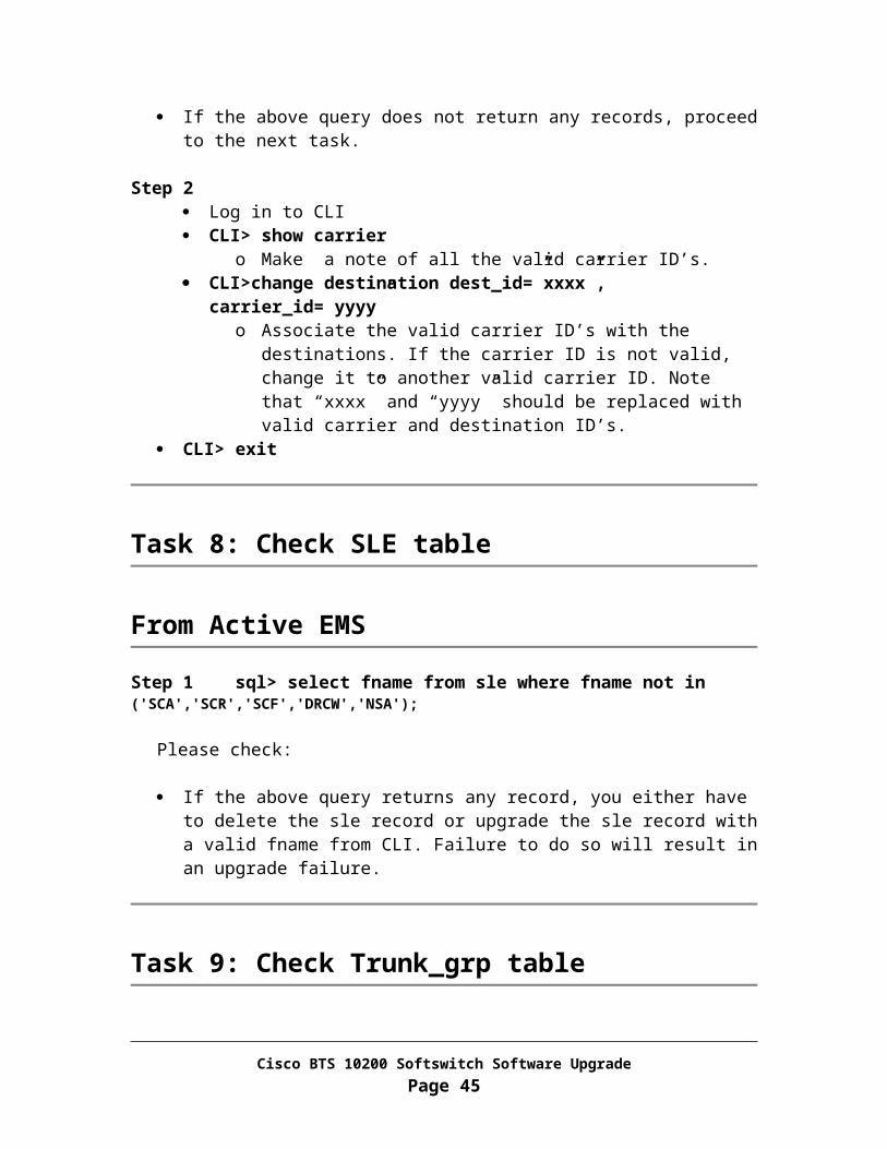
0 1
Continuous Hardware disk slot lay out:
CD-ROM Disk 0
Disk 1
Step 3 Place new disk labeled as “Release 4.5.0 EMS side B disk0, 1” in slot 0
Step 4 Power on the machine and allow the system to boot up by monitoring the boot process thru console.
For Netra 1280 machine, please execute the following command from console:
<lom>poweron
For other type of hardware, please use the power button to turn on the power.
Step 5 Log in as root thru console, use password “opticall”
Step 6 Rebuild network interface hardware configuration on disk
<hostname># cp –p /etc/path_to_inst /etc/path_to_inst.save
<hostname># egrep -iv “qfe|ce|eri|bge|hme|pci_pci” /etc/path_to_inst.save > /etc/path_to_inst
Step 7 Rebuild the hardware configuration
<hostname># reboot -- -r
Wait for the system to boot up. Then log in as root. Verify the Ethernet port assignment in the /etc/path_to_inst file.
Step 8 Restore interfaces:
<hostname># ifconfig <primary interface name> plumb
o Use Interface Name recorded in Chapter 3, Task 3
<hostname># ifconfig <primary interface name> <Interface IP> netmask <NETMASK> broadcast + up
Cisco BTS 10200 Softswitch Software UpgradePage 45

o Use IP and NETMASK recorded in Chapter 3, Task 3 for the interface
Add static routes to reach Domain Name Server and Network File Server:o <hostname># echo “route add -net <network to reach DNS>
<gateway IP>” >> /etc/rc3.d/S96StaticRouteso <hostname># /etc/rc3.d/S96StaticRoutes
Example:
o If the primary network manager interface for the machine is CE0, run “ifconfig ce0”, you should have following output:
ce0: flags=1000843<UP,BROADCAST,RUNNING,MULTICAST,IPv4> mtu 1500 index 2 inet 10.89.183.148 netmask ffffff00 broadcast 10.89.183.255 ether 0:3:ba:9d:68:85
o If the DNS server is on network “10.89.0.0”, then add gateway 10.89.183.254 to reach that network with following command:
<hostname># echo “route add -net 10.89.0.0 10.89.183.254” >> /etc/rc3.d/S96StaticRoutes
<hostname># /etc/rc3.d/S96StaticRoutes
Step 9 Reset ssh keys:
<hostname># \rm /.ssh/known_hosts
Step 10 sftp the opticall.cfg file from Network File Server (opticall.cfg was constructed in Chapter 3, Task 2) and place it under /etc directory.
Step 11 sftp resolv.conf file from Primary EMS Side A and place it under /etc directory.
<hostname># sftp <Side A EMS IP>sftp> get /etc/resolv.conf /etc/resolv.confsftp> exit
Step 12 Run script program to replace the hostname
<hostname># cd /opt/ems/upgrade
<hostname># DoTheChange -s
The system will reboot when the script DoTheChange completes its run
Cisco BTS 10200 Softswitch Software UpgradePage 46

Step 13 Wait for the system to boot up. Then log in as root.
Step 14 Editing /etc/default/init:
<hostname># vi /etc/default/init
Remove lines and keep only the following lines:
#TZ=US/CentralCMASK=022
For an example:
The original /etc/default/init file before line removal:
# @(#)init.dfl 1.5 99/05/26## This file is /etc/default/init. /etc/TIMEZONE is a symlink to this file.# This file looks like a shell script, but it is not. To maintain# compatibility with old versions of /etc/TIMEZONE, some shell constructs# (i.e., export commands) are allowed in this file, but are ignored.## Lines of this file should be of the form VAR=value, where VAR is one of# TZ, LANG, CMASK, or any of the LC_* environment variables.#TZ=US/CentralCMASK=022LC_COLLATE=en_US.ISO8859-1LC_CTYPE=en_US.ISO8859-1LC_MESSAGES=CLC_MONETARY=en_US.ISO8859-1LC_NUMERIC=en_US.ISO8859-1LC_TIME=en_US.ISO8859-1
The /etc/default/init file after line removal:
# @(#)init.dfl 1.5 99/05/26## This file is /etc/default/init. /etc/TIMEZONE is a symlink to this file.# This file looks like a shell script, but it is not. To maintain# compatibility with old versions of /etc/TIMEZONE, some shell constructs# (i.e., export commands) are allowed in this file, but are ignored.## Lines of this file should be of the form VAR=value, where VAR is one of
Cisco BTS 10200 Softswitch Software UpgradePage 47

# TZ, LANG, CMASK, or any of the LC_* environment variables.#TZ=US/CentralCMASK=022
Step 15 Verify interface hardware configuration match to the host configuration:
<hostname># egrep –i “qfe|ce|eri|bge|hme” /etc/path_to_inst
<hostname># ls -l /etc/hostname.*
If the interface names match from the above two outputs, please continue on Step 16.
If the interface names do NOT match, please match them by changing the postfix of hostname.*.
For an example:
Output from “egrep –i “qfe|ce|eri|bge|hme” /etc/path_to_inst” is:
"/pci@1f,4000/network@1,1" 0 "hme""/pci@1f,4000/pci@4/SUNW,qfe@0,1" 0 "qfe""/pci@1f,4000/pci@4/SUNW,qfe@1,1" 1 "qfe""/pci@1f,4000/pci@4/SUNW,qfe@2,1" 2 "qfe""/pci@1f,4000/pci@4/SUNW,qfe@3,1" 3 "qfe"
Output from “ls -l /etc/hostname.*” is:
-rw-r--r-- 1 root other 14 May 16 16:03 /etc/hostname.hme0-rw-r--r-- 1 root other 14 May 16 16:04 /etc/hostname.hme0:1-rw-r--r-- 1 root other 14 May 16 16:04 /etc/hostname.eri0-rw-r--r-- 1 root other 14 May 16 16:04 /etc/hostname.eri0:1
After change, the output should be:
-rw-r--r-- 1 root other 14 May 16 16:03 /etc/hostname.hme0-rw-r--r-- 1 root other 14 May 16 16:04 /etc/hostname.hme0:1-rw-r--r-- 1 root other 14 May 16 16:04 /etc/hostname.qfe0-rw-r--r-- 1 root other 14 May 16 16:04 /etc/hostname.qfe0:1
Step 16 Correct DNS server IP address in the named daemon configuration file. Please use the name.conf file on EMS side A as reference.
<hostname># vi /etc/named.conf
Cisco BTS 10200 Softswitch Software UpgradePage 48

Correct the IP of each DNS server that is serving the BTS system
Step 17 Reboot the machine to pick up new TIMEZONE and interface setting:
<hostname># sync; sync; reboot
Wait for the system to boot up. Then log in as root.
Step 18 <hostname># /opt/ems/utils/updMgr.sh –split_hub
Step 19 <hostname># svcadm disable system/cron
Step 20 CDR delimiter customization is not retained after software upgrade. If this system has been customized, either the Customer or Cisco Support Engineer must manually customize again to keep the same customization.
<hostname># cd /opt/bdms/bin <hostname># vi platform.cfg
Find the section for the command argument list for the BMG process
Customize the CDR delimiters in the “Args=” line
Example:
Args=-port 15260 -h localhost -u optiuser -p optiuser -fmt default_formatter -UpdIntvl 3300 -ems_local_dn blg-aSYS14EMS.cisco.com -FD semicolon -RD verticalbar
Step 21 <hostname># platform start –i oracle
Step 22 Log in as Oracle user.
<hostname># su – oracle
<hostname>$ cd /opt/oracle/admin/utl
Step 23 Set Oracle DB to simplex mode:
<hostname>$ rep_toggle –s optical2 –t set_simplex
Answer “y” when prompt Answer “y” again when prompt
Cisco BTS 10200 Softswitch Software UpgradePage 49

Task 7: Upgrade CA/FS Side B to the new release
Warning Do not proceed if you don’t have a pre-constructed opticall.cfg file for the system. The opticall.cfg file should already be constructed in Chapter 4, Task 2.
From CA/FS side B
Step 1 Power off the machine
Step 2 Remove disk0 from slot 0 off the machine and label it as “Release 3.5.4 CA/FS side B disk0”
SunFire V120 disk slot lay out:
CD-ROM Disk 0 Disk 1 SunFire V240 disk slot lay out:
Disk 2 Disk 3
Disk 0 Disk 1 DVD-ROM SunFire V440 disk slot lay out:
Disk 3 DVD-ROM
Disk 2
Disk 1
Disk 0 Netra 1280 disk slot lay out:
DVD-ROM
Disk 1
Disk 0 Netra 20 disk slot lay out:
Cisco BTS 10200 Softswitch Software UpgradePage 50
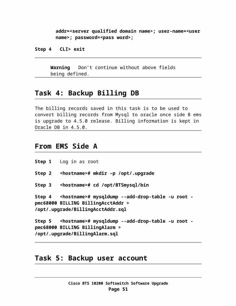
DISK
0
DISK
1
DVDROM
Continuous Hardware disk slot lay out:
CD-ROM Disk 0 Disk 2
Disk 1 Disk 3
Step 3 Place new disk labeled as “Release 4.5.0 CA/FS side B disk0, 1” in slot 0
Step 4 Power on the machine and allow the system to boot up by monitoring the boot process through console.
For Netra 1280 machine, please execute the following command from console:
<lom>poweron
For other type of hardware, please use the power button to turn on the power.
Step 5 Log in as root from console.
Step 6 Rebuild network interface hardware configuration on disk
<hostname># cp –p /etc/path_to_inst /etc/path_to_inst.save
<hostname># egrep -iv “qfe|ce|eri|bge|hme|pci_pci” /etc/path_to_inst.save > /etc/path_to_inst
Step 7 Rebuild the hardware configuration
<hostname># reboot -- -r
Wait for the system to boot up. Then log in as root. Verify the Ethernet port assignment in the /etc/path_to_inst file.
Step 8 Restore interfaces:
<hostname># ifconfig <primary interface name> plumb
o Use Interface Name recorded in “Chapter 6, Task 5”
Cisco BTS 10200 Softswitch Software UpgradePage 51

<hostname># ifconfig <primary interface name> <Interface IP> netmask <NETMASK> broadcast + up
o Use IP and NETMASK recorded in “Chapter 6, Task 5”
Add static routes to reach Domain Name Server and Network File Server using “route add …” command:
o Example: route add -net 10.89.224.1 10.89.232.254
Where: 10.89.224.1 is the destination DNS server IP 10.89.232.254 is the gateway IP
Step 9 Reset ssh keys:
<hostname># \rm /.ssh/known_hosts
Step 10 sftp the opticall.cfg file from Network File Server (opticall.cfg was constructed in Chapter 4, Task 2) and place it under /etc directory.
Step 11 sftp resolv.conf file from Primary CA/FS Side A and place it under /etc directory.
<hostname># sftp <Side A CA/FS IP>sftp> get /etc/resolv.conf /etc/resolv.confsftp> exit
Step 12 Run script program to replace the hostname
<hostname># cd /opt/ems/upgrade
<hostname># DoTheChange -s
The system will reboot when the script DoTheChange completes its run
Step 13 Wait for the system to boot up. Then log in as root.
Step 14 Editing /etc/default/init:
<hostname># vi /etc/default/init
Remove lines and keep only the following lines:
#TZ=US/CentralCMASK=022
Cisco BTS 10200 Softswitch Software UpgradePage 52

For an example:
The original /etc/default/init file before line removal:
# @(#)init.dfl 1.5 99/05/26## This file is /etc/default/init. /etc/TIMEZONE is a symlink to this file.# This file looks like a shell script, but it is not. To maintain# compatibility with old versions of /etc/TIMEZONE, some shell constructs# (i.e., export commands) are allowed in this file, but are ignored.## Lines of this file should be of the form VAR=value, where VAR is one of# TZ, LANG, CMASK, or any of the LC_* environment variables.#TZ=US/CentralCMASK=022LC_COLLATE=en_US.ISO8859-1LC_CTYPE=en_US.ISO8859-1LC_MESSAGES=CLC_MONETARY=en_US.ISO8859-1LC_NUMERIC=en_US.ISO8859-1LC_TIME=en_US.ISO8859-1
The /etc/default/init file after line removal:
# @(#)init.dfl 1.5 99/05/26## This file is /etc/default/init. /etc/TIMEZONE is a symlink to this file.# This file looks like a shell script, but it is not. To maintain# compatibility with old versions of /etc/TIMEZONE, some shell constructs# (i.e., export commands) are allowed in this file, but are ignored.## Lines of this file should be of the form VAR=value, where VAR is one of# TZ, LANG, CMASK, or any of the LC_* environment variables.#TZ=US/CentralCMASK=022
Step 15 Verify interface hardware configuration match to the host configuration:
<hostname># egrep –i “qfe|ce|eri|bge|hme” /etc/path_to_inst
<hostname># ls –l /etc/hostname.*
Cisco BTS 10200 Softswitch Software UpgradePage 53

If the interface names match from the above two outputs, please continue on Step 16.
If the interface names do NOT match, please match them by changing the postfix of hostname.*.
For an example:
Output from “egrep –i “qfe|ce|eri|bge|hme” /etc/path_to_inst” is:
"/pci@1f,4000/network@1,1" 0 "hme""/pci@1f,4000/pci@4/SUNW,qfe@0,1" 0 "qfe""/pci@1f,4000/pci@4/SUNW,qfe@1,1" 1 "qfe""/pci@1f,4000/pci@4/SUNW,qfe@2,1" 2 "qfe""/pci@1f,4000/pci@4/SUNW,qfe@3,1" 3 "qfe""/pci@1f,2000/pci@1/SUNW,qfe@0,1" 4 "qfe""/pci@1f,2000/pci@1/SUNW,qfe@1,1" 5 "qfe""/pci@1f,2000/pci@1/SUNW,qfe@2,1" 6 "qfe""/pci@1f,2000/pci@1/SUNW,qfe@3,1" 7 "qfe"
Output from “ls -l /etc/hostname.*” is:
-rw-r--r-- 1 root other 14 Jun 10 11:25 hostname.hme0-rw-r--r-- 1 root other 14 Jun 10 11:25 hostname.eri0-rw-r--r-- 1 root other 13 Jun 10 11:25 hostname.eri1-rw-r--r-- 1 root other 13 Jun 10 11:25 hostname.eri1:1-rw-r--r-- 1 root other 14 Jun 10 11:25 hostname.eri1:2-rw-r--r-- 1 root other 12 Jun 10 11:25 hostname.eri1:3-rw-r--r-- 1 root other 13 Jun 10 11:25 hostname.eri2-rw-r--r-- 1 root other 13 Jun 10 11:25 hostname.eri2:1-rw-r--r-- 1 root other 14 Jun 10 11:25 hostname.eri2:2-rw-r--r-- 1 root other 12 Jun 10 11:25 hostname.eri2:3
After change, the output should be:
-rw-r--r-- 1 root other 14 Jun 10 11:25 hostname.hme0-rw-r--r-- 1 root other 14 Jun 10 11:25 hostname.qfe0-rw-r--r-- 1 root other 13 Jun 10 11:25 hostname.qfe1-rw-r--r-- 1 root other 13 Jun 10 11:25 hostname.qfe1:1-rw-r--r-- 1 root other 14 Jun 10 11:25 hostname.qfe1:2-rw-r--r-- 1 root other 12 Jun 10 11:25 hostname.qfe1:3-rw-r--r-- 1 root other 13 Jun 10 11:25 hostname.qfe2-rw-r--r-- 1 root other 13 Jun 10 11:25 hostname.qfe2:1-rw-r--r-- 1 root other 14 Jun 10 11:25 hostname.qfe2:2-rw-r--r-- 1 root other 12 Jun 10 11:25 hostname.qfe2:3
Cisco BTS 10200 Softswitch Software UpgradePage 54
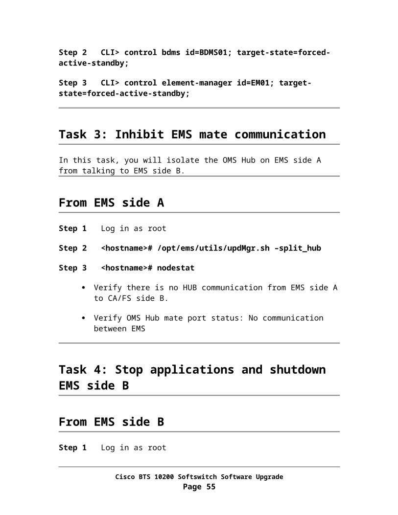
Step 16 Correct DNS server IP address in the named daemon configuration file. Please use the name.conf file on EMS side A as reference.
<hostname># vi /etc/named.conf
Correct the IP of each DNS server that is serving the BTS system
Step 17 Reboot the machine to pick up new TIMEZONE and interface setting:
<hostname># sync; sync; reboot
Wait for the system to boot up. Then log in as root.
Step 18 Check for configuration errors
<hostname># cd /opt/Build
<hostname># checkCFG –u
Correct errors generated by checkCFG Once the result is clean without errors, then proceed to the next step.
Step 19 Change the IPs for MGCP domain name from 4 physical IPs (2 physical IPs from primary CA/FS: 2P, and 2 physical IPs from secondary CA/FS: 2S) to two logical IPs: 2P + 2S 2L:
<hostname># vi /etc/hosts Delete 2 physical IPs came from primary CA/FS.
Delete 2 physical IPs came from secondary CA/FS.
Add 2 new logical IPs for the MGCP domain name in release 4.5.0.
Check to make sure there are only 2 logical IP addresses left for mgcp domain name
Step 20 <hostname># install.sh -upgrade
Step 21 Answer "y" when prompted. This process will take up to 15 minutes to complete.
Answer "y" if prompted for reboot Wait for the system to boot up. Then log in as root.
Edit /etc/hosts file to make sure there are only 2 logical IP addresses left for mgcp domain name
Cisco BTS 10200 Softswitch Software UpgradePage 55

Step 22 Update CA/FS platform.cfg files:
<hostname># cd /opt/Build/btsauto
<hostname># update_platform.sh
Step 23 <hostname># platform start
Step 24 <hostname># mv /etc/rc3.d/_S99platform /etc/rc3.d/S99platform
Task 8: Migrate oracle data
From EMS side B
Step 1 Copying data.
<hostname>$ su - oracle
<hostname>$ cd /opt/oracle/admin/upd
<hostname>$ java dba.dmt.DMMgr -upgrade -auto ./config/3.5.4_to_4.5.0.cfg
Step 2 Verify the data migration is a success.
<hostname>$ echo $?
Verify the returned value is 0. If not, please sftp /opt/oracle/admin/upd/DMMgr.log file off system and call
for immediate technical assistance.
Step 3 <hostname>$ java dba.adm.DBUsage -sync
Verify Number of tables “unable-to-sync” is 0 If not, please contract Cisco support
Step 4 <hostname>$ cd /opt/oracle/opticall/create
Step 5 <hostname>$ dbinstall optical2 -load dbsize
Step 6 <hostname>$ exit
Step 7 <hostname># platform start
Cisco BTS 10200 Softswitch Software UpgradePage 56

Step 8 <hostname># svcadm enable system/cron
Step 9 <hostname># mv /etc/rc3.d/_S99platform /etc/rc3.d/S99platform
Task 9: Restore billing address and billing alarm
From EMS side B
Step 1 Log in as root
Step 2 <hostname># mkdir –p /opt/.upgrade
Step 3 <hostname># cd /opt/.upgrade
Step 4 Get old billing data from EMS side A machine:
<hostname># sftp <EMS side A hostname> sftp> cd /opt/.upgrade
sftp> mget *
sftp> exit
Step 5 <hostname># cd /opt/ems/utils
Step 6 <hostname># upgrade_billing
Step 7 <hostname># su - oracle
Step 8 <hostname>$ sqlplus optiuser/optiuser < /opt/.upgrade/upgrade_billing.sql
Step 9 <hostname>$ exit
Task 10: To install CORBA on EMS side B, please follow Appendix I.
Cisco BTS 10200 Softswitch Software UpgradePage 57

Chapter 7Prepare Side A Systems for Upgrade
Task 1: Control SS7 trunk groups out of service on release 3.5.4
From EMS side A
Step 1 If there is NO CLI script prepared, please follow steps specified in Appendix Q and then continue on Step 3.
Step 2 If there are CLI scripts prepared, log in to the Network File Server where the pre-prepared script resides. SFTP the script to EMS side A log in as CLI user and put script under /opt/ems/ftp/deposit directory.
Wait for the batch process to pick up the script from /opt/ems/ftp/deposit directory and provision it into the system.
Keep running “ls” command from /opt/ems/ftp/deposit directory and till the file is gone
<hostname># cd /opt/ems/report <hostname># egrep Failed:0 <filename>.html Verify the system returns an output. If there is no output returned, please
check for errors in the report file.
Step 3 Check the status of each SS7 trunk group – the admin state should be out of service:
Log in as CLI user to EMS side A CLI> status trunk-grp id=<SS7 trunk group ID>;
Task 2: Control SS7 links out of service
In this task, you will tear down SS7 links in OMNI before switchover activity to side B.
Cisco BTS 10200 Softswitch Software UpgradePage 58

From CA/FS side A
Step 1 Log in as root
Step 2 Deactivate SS7 Links on CA/FS side A
1. <hostname># termhandler -node a7n1
OMNI [date] #1:deact-slk:slk=< link on CA/FS side A >; Enter y to continue
Repeat above two steps for each active link
2. OMNI [date] #2:display-slk;
Enter “y” to continue Verify that the state of each link is INACTIVE
3. OMNI[date]#3:quit
Task 3: Force side A systems to standby
This procedure will force the side A systems to standby and force the side B systems to active.
Note In the commands below, "xxx", "yyy" or "zzz" is the instance for the process on your system.
From EMS side A
Step 1 Log in as CLI user
Step 2 CLI> control call-agent id=CAxxx; target-state=forced-standby-active;
Step 3 CLI> control feature-server id=FSPTCzzz; target-state=forced-standby-active;
Step 4 CLI> control feature-server id=FSAINyyy; target-state=forced-standby-active;
Step 5 CLI> control bdms id=BDMS01; target-state=forced-standby-active;
Cisco BTS 10200 Softswitch Software UpgradePage 59

Step 6 CLI> control element-manager id=EM01; target-state=forced-standby-active;
Step 7 CLI session will terminate when the last CLI command completes
Note If the system failed to switchover from side A to side B, please contact Cisco Support to determine whether the system should fallback. If fallback is needed, please following Appendix G.
Task 4: Provision 4.5.0 SS7 configuration
From EMS side B
Note: The script used in this task must only migrate 3.5.4 SS7 configuration from OMNI based to ITP based with no control commands. If you don’t have a pre-created CLI provisioning script for adding SS7 configuration information to the new release, you must contact Cisco Support.
Step 1 If there is NO CLI script prepared, please follow steps specified in Appendix S and Appendix T and skip over Step 2.
Step 2 If there are CLI scripts prepared, log in to the Network File Server where the pre-prepared script resides. SFTP the script to EMS side B log in as CLI user and put script under /opt/ems/ftp/deposit directory.
Wait for the batch process to pick up the script from /opt/ems/ftp/deposit directory and provision it into the system.
Keep running “ls” command from /opt/ems/ftp/deposit directory and till the file is gone
<hostname># cd /opt/ems/report <hostname># egrep Failed:0 <filename>.html Verify the system returns an output. If there is no output returned, please
check for errors in the report file.
Task 5: Control SS7 trunk groups in service
From EMS side B
Cisco BTS 10200 Softswitch Software UpgradePage 60

Step 1 If there is NO CLI script prepared, please follow steps specified in Appendix R and then continue on Step 3.
Step 2 If there are CLI scripts prepared, log in to the Network File Server where the pre-prepared script resides. SFTP the script to EMS side B log in as CLI user and put script under /opt/ems/ftp/deposit directory.
Wait for the batch process to pick up the script from /opt/ems/ftp/deposit directory and provision it into the system.
Keep running “ls” command from /opt/ems/ftp/deposit directory and till the file is gone
<hostname># cd /opt/ems/report <hostname># egrep Failed:0 <filename>.html Verify the system returns an output. If there is no output returned, please
check for errors in the report file.
Step 3 Check the status of each SS7 trunk group – admin state should in service:
Log in as CLI user to EMS side B CLI> status trunk-grp id=<SS7 trunk group ID>;
Step 4 Please follow steps in Appendix U to verify the new SS7 configuration is working correctly. If the system fails to make new SS7 calls, please contact Cisco Support immediately.
Task 6: Sync Data from EMS side B to CA/FS side B
In this task, you will sync from EMS to CA/FS for several inter-platform migrated tables.
From EMS side B
Step 1 Log in as ciscouser (password: ciscosupport)
Step 2 CLI> sync annc_tg_profile master=EMS; target=CAxxx;
Step 3 CLI> sync trunk_grp master=EMS; target=CAxxx;
Step 4 CLI> sync emergency_number_list master=EMS; target=CAxxx;
Step 5 CLI> sync pop master=EMS; target=FSPTCzzz;
Step 6 CLI> sync radius_profile master=EMS; target=FSPTCzzz;
Cisco BTS 10200 Softswitch Software UpgradePage 61

Step 7 CLI> sync pop master=EMS; target=FSAINyyy;
Step 8 CLI> sync subscriber-profile master=EMS; target=FSPTCzzz;
Step 9 CLI> sync cpsg master=EMS; target=CAxxx;
Step 10 CLI> sync ext2subscriber master=EMS; target=CAxxx;
Step 11 CLI> sync subscriber master=EMS; target=FSPTCzzz;
Step 12 CLI> exit
Task 7: Validate release 4.5.0 software operation
To verify the stability of the newly installed 4.5.0 Release, let CA/FS side B carry live traffic for period of time. Monitor the Cisco BTS 10200 Softswitch and the network. If there are any problems, please investigate and contact Cisco Support if necessary.
From EMS side B
Step 1 Verify that call processing using Appendix B.
Step 2 Log in as CLI user.
Step 3 CLI> audit database type=row-count;
Verify there is no error in the report and the database is not empty. If any table shows mis-match, then perform a detailed audit on these tables:
CLI> audit <table name>;
Step 4 Verify the SUP config is set up correctly
CLI> show sup-config; Verify refresh rate is set to 86400.
If not, do the following
CLI> change sup-config type=refresh_rate; value=86400;
Cisco BTS 10200 Softswitch Software UpgradePage 62

From EMS side A
Step 1 <hostname># ls /opt/bms/ftp/billing
If there are files listed, then SFTP the files to a mediation device on the network and remove the files from the /opt/bms/ftp/billing directory.
Note Once the system proves stable and you decide to move ahead with the upgrade, then you must execute subsequent tasks. If fallback is needed at this stage, please follow the fallback procedure in Appendix G.
Cisco BTS 10200 Softswitch Software UpgradePage 63

Chapter 8Upgrade Side A Systems
Task 1: Stop applications and shutdown EMS side A
From EMS side A
Step 1 Log in as root
Step 2 Record the IP address and netmask for the management interface of the system.
For an example, if the “hme0” is used for management interface, then execute the following command:
<hostname># ifconfig hme0
Record the IP address and netmask for the interface to be used in the next task.
IP: _____________ Netmask: ____________ Interface Name: ___________
Step 3 <hostname># mv /etc/rc3.d/S99platform /etc/rc3.d/_S99platform
Step 4 <hostname># platform stop all
Step 5 <hostname># sync; sync
Step 6 <hostname># shutdown –i5 –g0 –y
Task 2: Stop applications and shutdown CA/FS side A
From CA/FS side A
Step 1 Log in as root
Cisco BTS 10200 Softswitch Software UpgradePage 64
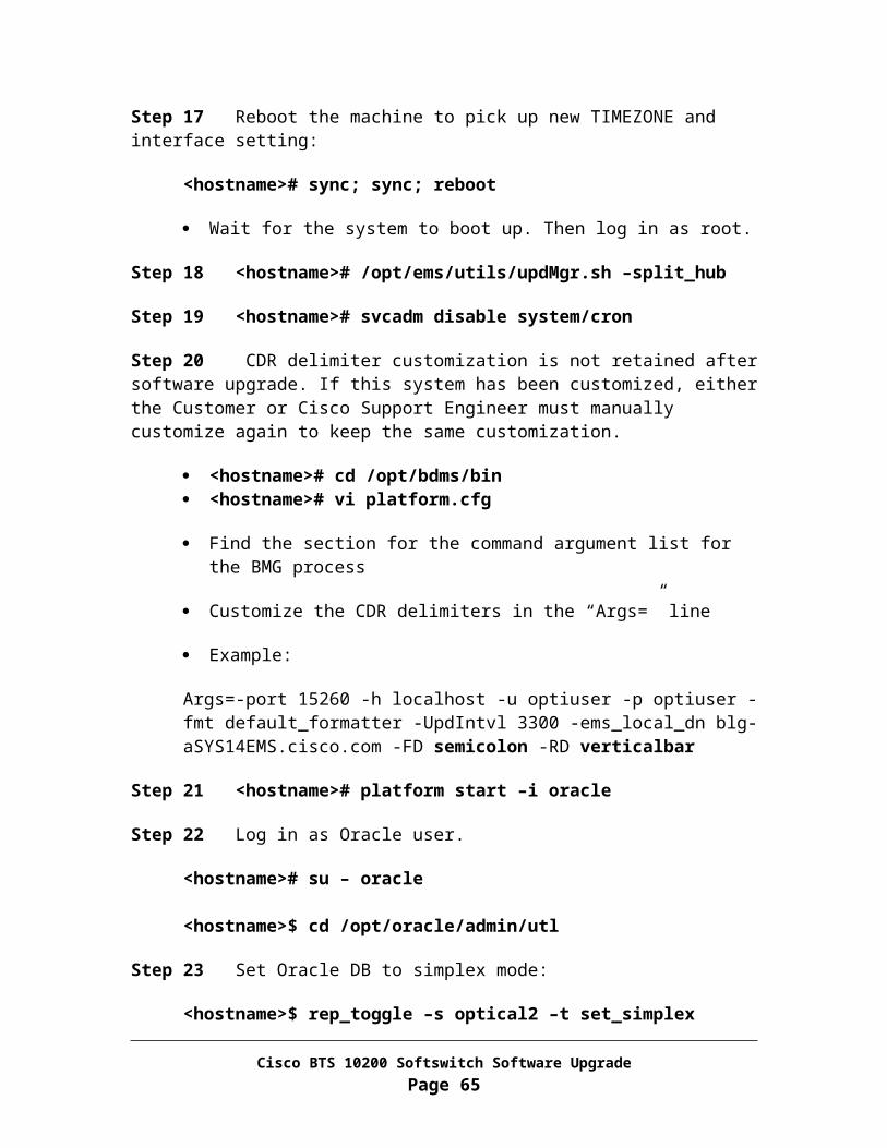
Step 2 Record the IP address and netmask for the management interface of the system.
For an example, if the “hme0” is used for management interface, then execute the following command:
<hostname># ifconfig hme0
Record the IP address and netmask for the interface to be used in the next task.
IP: _____________ Netmask: ____________ Interface Name: ___________
Step 3 <hostname># mv /etc/rc3.d/S99platform /etc/rc3.d/_S99platform
Step 4 <hostname># platform stop all
Step 5 <hostname># sync; sync
Step 6 <hostname># shutdown –i5 –g0 –y
Task 3: Upgrade EMS side A to the new release
From EMS side A
Step 1 Power off the machine
Step 2 Remove disk0 from slot 0 off the machine and label it as “Release 3.5.4 EMS side A disk0”
SunFire V120 disk slot lay out:
CD-ROM Disk 0 Disk 1 SunFire V240 disk slot lay out:
Disk 2 Disk 3
Disk 0 Disk 1 DVD-ROM SunFire V440 disk slot lay out:
Disk 3 DVD-ROM
Cisco BTS 10200 Softswitch Software UpgradePage 65

Disk 2
Disk 1
Disk 0 Netra 1280 disk slot lay out:
DVD-ROM
Disk 1
Disk 0 Netra 20 disk slot lay out:
DISK
0
DISK
1
DVDROM
Continuous Hardware disk slot lay out:
CD-ROM Disk 0
Disk 1
Step 3 Place new disk labeled as “Release 4.5.0 EMS side A disk0, 1” in slot 0
Step 4 Power on the machine and allow the system to boot up by monitoring the boot process through console.
For Netra 1280 machine, please execute the following command from console:
<lom>poweron
For other type of hardware, please use the power button to turn on the power.
Step 5 Log in as root from console.
Step 6 Rebuild network interface hardware configuration on disk
Cisco BTS 10200 Softswitch Software UpgradePage 66

<hostname># cp –p /etc/path_to_inst /etc/path_to_inst.save
<hostname># egrep -iv “qfe|ce|eri|bge|hme|pci_pci” /etc/path_to_inst.save > /etc/path_to_inst
Step 7 Rebuild the hardware configuration
<hostname># reboot -- -r
Wait for the system to boot up. Then log in as root. Verify the Ethernet port assignment in the /etc/path_to_inst file.
Step 8 Restore interfaces:
<hostname># ifconfig <primary interface name> plumb
o Use Interface Name recorded in Chapter 3, Task 3
<hostname># ifconfig <primary interface name> <Interface IP> netmask <NETMASK> broadcast + up
o Use IP and NETMASK recorded in Chapter 3, Task 3 for the interface
Add static routes to reach Domain Name Server and Network File Server:o <hostname># echo “route add -net <network to reach DNS>
<gateway IP>” >> /etc/rc3.d/S96StaticRouteso <hostname># /etc/rc3.d/S96StaticRoutes
Example:
o If the primary network manager interface for the machine is CE0, run “ifconfig ce0”, you should have following output:
ce0: flags=1000843<UP,BROADCAST,RUNNING,MULTICAST,IPv4> mtu 1500 index 2 inet 10.89.183.148 netmask ffffff00 broadcast 10.89.183.255 ether 0:3:ba:9d:68:85
o If the DNS server is on network “10.89.0.0”, then add gateway 10.89.183.254 to reach that network with following command:
<hostname># echo “route add -net 10.89.0.0 10.89.183.254” >> /etc/rc3.d/S96StaticRoutes
<hostname># /etc/rc3.d/S96StaticRoutes
Step 9 Reset ssh keys:
Cisco BTS 10200 Softswitch Software UpgradePage 67

<hostname># \rm /.ssh/known_hosts
Step 10 sftp the opticall.cfg and resolv.conf from Secondary EMS side B and place it under /etc directory.
<hostname># sftp <Side B EMS IP>sftp> get /etc/resolv.conf /etc/resolv.confsftp> get /etc/opticall.cfg /etc/opticall.cfgsftp> get /etc/named.conf /etc/named.confsftp> exit
Step 11 Run script program to replace the hostname
<hostname># cd /opt/ems/upgrade
<hostname># DoTheChange -p
The system will reboot when the script DoTheChange completes its run
Step 12 Wait for the system to boot up. Then Log in as root.
Step 13 Verify interface hardware configuration match to the host configuration:
<hostname># egrep –i “qfe|ce|eri|bge|hme” /etc/path_to_inst
<hostname># ls –l /etc/hostname.*
If the interface names match from the above two outputs, please continue on Step 15.
If the interface names do NOT match, please match them by changing the postfix of hostname.*.
For an example:
Output from “egrep –i “qfe|ce|eri|bge|hme” /etc/path_to_inst” is:
"/pci@1f,4000/network@1,1" 0 "hme""/pci@1f,4000/pci@4/SUNW,qfe@0,1" 0 "qfe""/pci@1f,4000/pci@4/SUNW,qfe@1,1" 1 "qfe""/pci@1f,4000/pci@4/SUNW,qfe@2,1" 2 "qfe""/pci@1f,4000/pci@4/SUNW,qfe@3,1" 3 "qfe"
Output from “ls -l /etc/hostname.*” is:
Cisco BTS 10200 Softswitch Software UpgradePage 68

-rw-r--r-- 1 root other 14 May 16 16:03 /etc/hostname.hme0-rw-r--r-- 1 root other 14 May 16 16:04 /etc/hostname.hme0:1-rw-r--r-- 1 root other 14 May 16 16:04 /etc/hostname.eri0-rw-r--r-- 1 root other 14 May 16 16:04 /etc/hostname.eri0:1
After change, the output should be:
-rw-r--r-- 1 root other 14 May 16 16:03 /etc/hostname.hme0-rw-r--r-- 1 root other 14 May 16 16:04 /etc/hostname.hme0:1-rw-r--r-- 1 root other 14 May 16 16:04 /etc/hostname.qfe0-rw-r--r-- 1 root other 14 May 16 16:04 /etc/hostname.qfe0:1
Step 14 Reboot the machine to pick up new interface setting:
<hostname># sync; sync; reboot
Wait for the system to boot up. Then log in as root.
Step 15 CDR delimiter customization is not retained after software upgrade. If this system has been customized, either the Customer or Cisco Support Engineer must manually customize again to keep the same customization.
<hostname># cd /opt/bdms/bin <hostname># vi platform.cfg
Find the section for the command argument list for the BMG process
Customize the CDR delimiters in the “Args=” line
Example:
Args=-port 15260 -h localhost -u optiuser -p optiuser -fmt default_formatter -UpdIntvl 3300 -ems_local_dn blg-aSYS14EMS.cisco.com -FD semicolon -RD verticalbar
Step 16 <hostname># platform start
Task 4: Upgrade CA/FS Side A to the new release
From CA/FS side A
Step 1 Power off the machine
Cisco BTS 10200 Softswitch Software UpgradePage 69

Step 2 Remove disk0 from slot 0 off the machine and label it as “Release 3.5.4 CA/FS side A disk0”
SunFire V120 disk slot lay out:
CD-ROM Disk 0 Disk 1 SunFire V240 disk slot lay out:
Disk 2 Disk 3
Disk 0 Disk 1 DVD-ROM SunFire V440 disk slot lay out:
Disk 3 DVD-ROM
Disk 2
Disk 1
Disk 0 Netra 1280 disk slot lay out:
DVD-ROM
Disk 1
Disk 0 Netra 20 disk slot lay out:
DISK
0
DISK
1
DVDROM
Continuous Hardware disk slot lay out:
CD-ROM Disk 0 Disk 2
Cisco BTS 10200 Softswitch Software UpgradePage 70

Disk 1 Disk 3
Step 3 Place new disk labeled as “Release 4.5.0 CA/FS side A disk0, 1” in slot 0
Step 4 Power on the machine and allow the system to boot up by monitoring the boot process thru console.
For Netra 1280 machine, please execute the following command from console:
<lom>poweron
For other type of hardware, please use the power button to turn on the power.
Step 5 Log in as root.
Step 6 Rebuild network interface hardware configuration on disk
<hostname># cp –p /etc/path_to_inst /etc/path_to_inst.save
<hostname># egrep -iv “qfe|ce|eri|bge|hme|pci_pci” /etc/path_to_inst.save > /etc/path_to_inst
Step 7 Rebuild the hardware configuration
<hostname># reboot -- -r
Wait for the system to boot up. Then log in as root. Verify the Ethernet port assignment in the /etc/path_to_inst file.
Step 8 Restore interfaces:
<hostname># ifconfig <interface name> plumb
o Use Interface Name recorded in Chapter 3, Task 3.
<hostname># ifconfig <interface name> <Interface IP> netmask <NETMASK> broadcast + up
o Use IP and NETMASK recorded in Chapter 3, Task 3
Add static routes to reach Domain Name Server and Network File Server using “route add …” command:
o Example: route add -net 10.89.0.0 10.89.232.254
Cisco BTS 10200 Softswitch Software UpgradePage 71
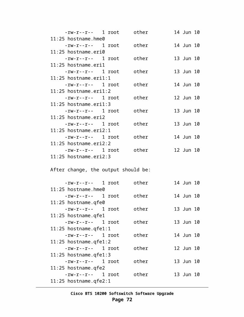
Where: 10.89.0.0 is the destination DNS server network IP 10.89.232.254 is the gateway IP
Step 9 Reset ssh keys:
<hostname># \rm /.ssh/known_hosts
Step 10 sftp required files.
<hostname># sftp <Side B CA/FS IP>sftp> get /etc/resolv.conf /etc/resolv.confsftp> get /etc/opticall.cfg /etc/opticall.cfgsftp> get /etc/named.conf /etc/named.confsftp> exit
Step 11 Run script program to replace the hostname
<hostname># cd /opt/ems/upgrade
<hostname># DoTheChange -p
The system will reboot when the script DoTheChange completes its run
Step 12 Wait for the system to boot up. Then Log in as root.
Step 13 Verify interface hardware configuration match to the host configuration:
<hostname># egrep –i “qfe|ce|eri|bge|hme” /etc/path_to_inst
<hostname># ls –l /etc/hostname.*
If the interface names match from the above two outputs, please continue on Step 15.
If the interface names do NOT match, please match them by changing the postfix of hostname.*.
For an example:
Output from “egrep –i “qfe|ce|eri|bge|hme” /etc/path_to_inst” is:
"/pci@1f,4000/network@1,1" 0 "hme""/pci@1f,4000/pci@4/SUNW,qfe@0,1" 0 "qfe""/pci@1f,4000/pci@4/SUNW,qfe@1,1" 1 "qfe""/pci@1f,4000/pci@4/SUNW,qfe@2,1" 2 "qfe"
Cisco BTS 10200 Softswitch Software UpgradePage 72

"/pci@1f,4000/pci@4/SUNW,qfe@3,1" 3 "qfe""/pci@1f,2000/pci@1/SUNW,qfe@0,1" 4 "qfe""/pci@1f,2000/pci@1/SUNW,qfe@1,1" 5 "qfe""/pci@1f,2000/pci@1/SUNW,qfe@2,1" 6 "qfe""/pci@1f,2000/pci@1/SUNW,qfe@3,1" 7 "qfe"
Output from “ls -l /etc/hostname.*” is:
-rw-r--r-- 1 root other 14 Jun 10 11:25 hostname.hme0-rw-r--r-- 1 root other 14 Jun 10 11:25 hostname.eri0-rw-r--r-- 1 root other 13 Jun 10 11:25 hostname.eri1-rw-r--r-- 1 root other 13 Jun 10 11:25 hostname.eri1:1-rw-r--r-- 1 root other 14 Jun 10 11:25 hostname.eri1:2-rw-r--r-- 1 root other 12 Jun 10 11:25 hostname.eri1:3-rw-r--r-- 1 root other 13 Jun 10 11:25 hostname.eri2-rw-r--r-- 1 root other 13 Jun 10 11:25 hostname.eri2:1-rw-r--r-- 1 root other 14 Jun 10 11:25 hostname.eri2:2-rw-r--r-- 1 root other 12 Jun 10 11:25 hostname.eri2:3
After change, the output should be:
-rw-r--r-- 1 root other 14 Jun 10 11:25 hostname.hme0-rw-r--r-- 1 root other 14 Jun 10 11:25 hostname.qfe0-rw-r--r-- 1 root other 13 Jun 10 11:25 hostname.qfe1-rw-r--r-- 1 root other 13 Jun 10 11:25 hostname.qfe1:1-rw-r--r-- 1 root other 14 Jun 10 11:25 hostname.qfe1:2-rw-r--r-- 1 root other 12 Jun 10 11:25 hostname.qfe1:3-rw-r--r-- 1 root other 13 Jun 10 11:25 hostname.qfe2-rw-r--r-- 1 root other 13 Jun 10 11:25 hostname.qfe2:1-rw-r--r-- 1 root other 14 Jun 10 11:25 hostname.qfe2:2-rw-r--r-- 1 root other 12 Jun 10 11:25 hostname.qfe2:3
Step 14 Reboot the machine to pick up new interface setting:
<hostname># sync; sync; reboot
Wait for the system to boot up. Then log in as root.
Step 15 Install the applications
<hostname># cd /opt/Build
<hostname># install.sh –upgrade
Step 16 Answer "y" when prompted. This process will take up to 15 minutes to complete.
Cisco BTS 10200 Softswitch Software UpgradePage 73
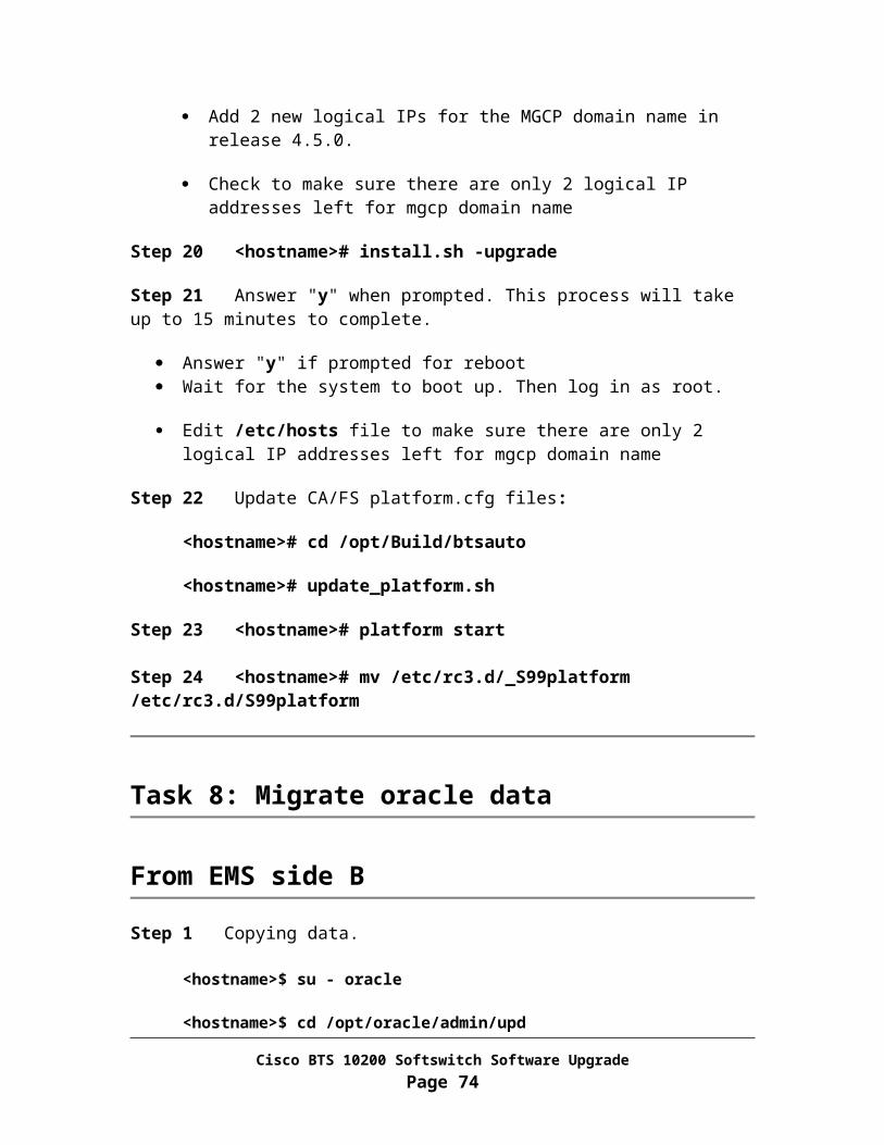
Answer "y" if prompted for reboot Wait for the system to boot up. Then Log in as root.
Step 17 Update CA/FS platform.cfg files:
<hostname># /opt/Build/btsauto/update_platform.sh
Step 18 <hostname># platform start
Step 19 <hostname># mv /etc/rc3.d/_S99platform /etc/rc3.d/S99platform
Task 5: Restore EMS mate communication
From EMS side B
Step 1 Log in as root
Step 2 <hostname># /opt/ems/utils/updMgr.sh –restore_hub
Step 3 <hostname># nodestat
Verify OMS Hub mate port status is established Verify HUB communication from EMS side B to CA/FS side A is established
Task 6: Copying oracle data
From EMS side A
Step 1 <hostname># svcadm disable system/cron
Step 2 Copying data.
<hostname>$ su – oracle
<hostname>$ cd /opt/oracle/admin/upd
<hostname>$ java dba.dmt.DMMgr –copy -auto
Step 3 Verify the data copy is a success.
Cisco BTS 10200 Softswitch Software UpgradePage 74

<hostname>$ echo $?
Verify the returned value is 0. If not, please sftp /opt/oracle/admin/upd/DMMgr.log file off system and call
for immediate technical assistance.
<hostname>$ exit
Step 4 <hostname># svcadm enable system/cron
Step 5 <hostname># mv /etc/rc3.d/_S99platform /etc/rc3.d/S99platform
Task 7: To install CORBA on EMS side A, please follow Appendix I.
Cisco BTS 10200 Softswitch Software UpgradePage 75

Chapter 9Finalizing Upgrade
Task 1: Switchover activity from side B to side A
This procedure will force the active system activity from side B to side A.
From EMS side B
Note In the commands below, "xxx", "yyy" or "zzz" is the instance for the process on your system.
Step 1 Log in to EMS side B as CLI user.
Step 2 CLI> control call-agent id=CAxxx; target-state=active-standby;
Step 3 CLI> control feature-server id=FSPTCyyy; target-state=active-standby;
Step 4 CLI> control feature-server id=FSAINzzz; target-state=active-standby;
Step 5 CLI> control bdms id=BDMS01; target-state=active-standby;
Step 6 CLI> control element-manager id=EM01; target-state=active-standby;
Step 7 CLI shell session should be terminated when last CLI commands completes.
Task 2: Enable Oracle DB replication on EMS side B
From EMS side B
Step 1 Restore Oracle DB to duplex mode:
<hostname># su - oracle
Cisco BTS 10200 Softswitch Software UpgradePage 76

<hostname>$ cd /opt/oracle/admin/utl
<hostname>$ rep_toggle –s optical2 –t set_duplex
o Answer “y” when prompto Answer “y” again when prompt
Step 2 <hostname>$ exit
Step 3 Terminate applications.
<hostname># platform stop all
Step 4 Re-start applications to activate DB toggle in duplex mode.
<hostname># platform start
Task 3: Synchronize handset provisioning data and check both mgw and cas-tg-profile tables
From EMS side A
Note In the commands below, "xxx", "yyy" or "zzz" is the instance for the process on your system.
Step 1 Log in as ciscouser (password: ciscosupport)
Step 2 CLI>sync termination master=CAxxx; target=EMS;
Verify the transaction is executed successfully.
Step 3 CLI>sync sc1d master=FSPTCzzz; target=EMS;
Verify the transaction is executed successfully
Step 4 CLI>sync sc2d master=FSPTCzzz; target=EMS;
Verify the transaction is executed successfully
Step 5 CLI>sync sle master=FSPTCzzz; target=EMS;
Cisco BTS 10200 Softswitch Software UpgradePage 77

Verify the transaction is executed successfully
Step 6 CLI>sync subscriber-feature-data master=FSPTCzzz; target=EMS;
Verify the transaction is executed successfully
Step 7 CLI> audit mgw;
If the TYPE mismatch is found between EMS Oracle DB and Call Agent, check the mismatched mgw to see if there is any trunk group associated with it. If it does, then the TYPE needs to be set to “TGW”. Otherwise, the TYPE should be set to “RGW”.
Command syntax for making the change:
CLI> change mgw id=<mgw id>; type=<RGW|TGW>;
Step 8 CLI> audit cas-tg-profile;
If the SIG_TYPE mismatch is found between EMS Oracle DB and Call Agent, here are steps for correction:
1. Find ID of the mismatched cas-tg-profile
2. Check MGCP_PKG_TYPE of trunk_grp associated with cas_tg_profile:
CLI>show trunk-grp tg_profile_id=<cas-tg-profile ID>;
3. If the MGCP_PKG_TYPE (for the given trunk grp) is MS, then SIG_TYPE should be set to MF in cas-tg-profile.
4. If the MGCP_PKG_TYPE (for the given trunk grp) is DT, then SIG_TYPE should be set to DTMF in cas-tg-profile.
5. Default for the SIG_TYPE in cas-tg-prfoile is MF
Command syntax for making the change:
CLI> change cas-tg-profile mgw id=<mgw id>; type=<RGW|TGW>;
Step 9 CLI>exit
Task 4: Restore customized cron jobs
Cisco BTS 10200 Softswitch Software UpgradePage 78

Please restore customized cron jobs by using the files saved on the network file server during system preparation stage in Chapter 4, Task 10. Please don’t copy the old crontab file over the new one. You may need to compare the back up version of the crontab file to the new crontab file to restore the previous settings. This should be done for all machines in the system.
Task 5: Synchronize the hosts and opticall.cfg files
From Primary CA/FS
Please ftp the /etc/hosts and /etc/opticall.cfg file to all other machines in the system.
Task 6: Verify system status
Verify that the system is operating properly before you leave the site.
Step 1 Verify that the side A systems are in the active state. Use Appendix A for this procedure.
Step 2 Verify that call processing is working without error. Use Appendix B for this procedure.
Step 3 Verify that provisioning is operational from CLI command line, and verify database. Use Appendix C for this procedure.
Step 4 Verify that there are no outstanding major or critical alarms. Use Appendix D for this procedure.
Step 5 Use Appendix E to verify that Oracle database and replication functions are working properly.
Step 6 If you have answered NO to any of the above questions (Step 1-5) do not proceed. Instead, use the backout procedure in Appendix H. Contact Cisco Support if you need assistance.
Cisco BTS 10200 Softswitch Software UpgradePage 79

Once the site has verified that all critical call-thru testing has successfully completed and the upgrade is complete, Appendix F should be executed to gather an up to date archive file of the system.
You have completed the Cisco BTS 10200 system upgrade process successfully.
Cisco BTS 10200 Softswitch Software UpgradePage 80
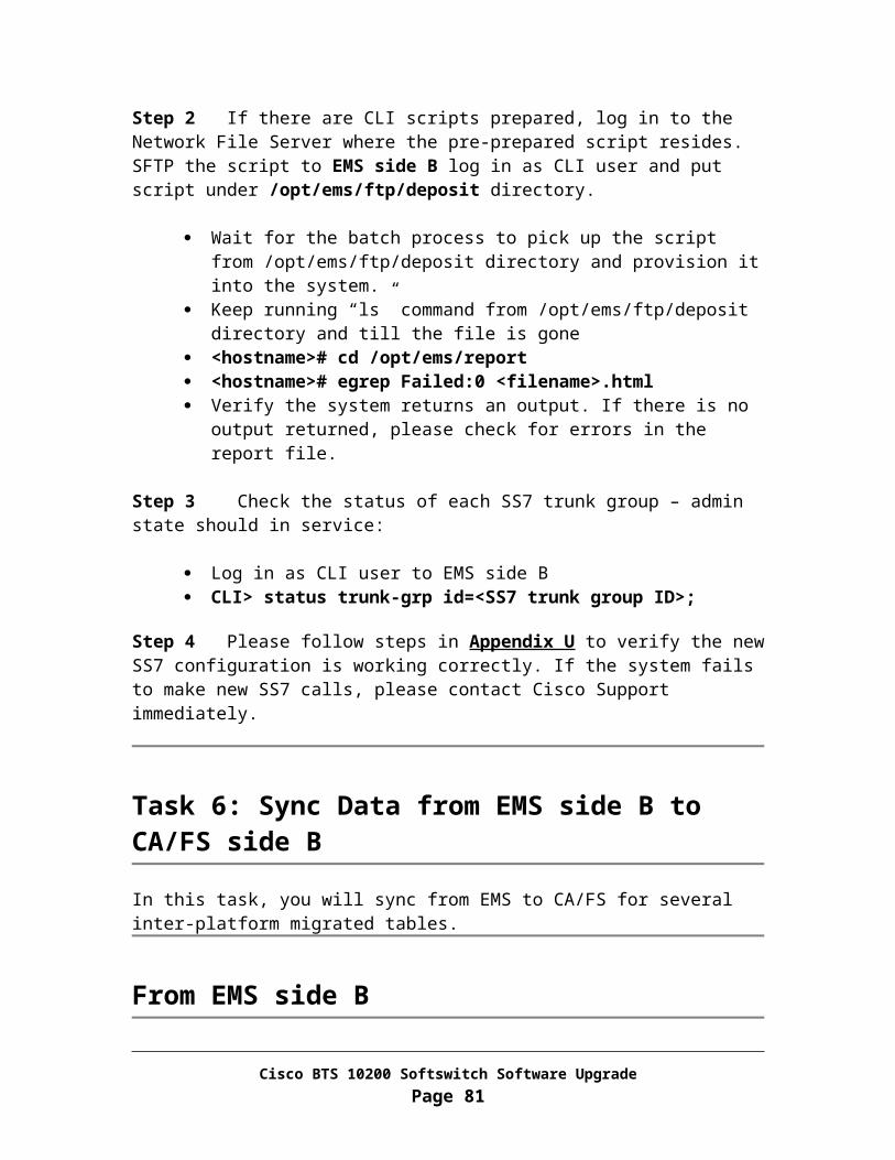
Chapter 10Post Upgrade Tasks
This chapter covers tasks that to be executed only after completing software upgrade successfully from release 3.5.4 to release 4.5.0.
Task 1: Change MGCP Domain IP addresses from Domain Name Servers
From each Domain Name Server that is serving the upgraded BTS 10200, remove the 2 physical IP addresses from primary CA/FS for MGCP domain name from DNS. In other words, change IPs for the MGCP domain name in the DNS database from: 2P + 2L 2L by removing two physical IPs from primary CA/FS.
Please refresh the DNS cache and make sure the new IP addresses are taking affect.
To verify the change has taken affect, please log in to both CA/FS machines and perform “nslookup” of the MGCP domain name.
Task 2: Correct ntp.conf File
From EMS side B
Step 1 sftp ntp.conf file from CA/FS side B:
<hostname># sftp <CA/FS side B hostname>
sftp> get /opt/BTSxntp/etc/ntp.conf /opt/BTSxntp/etc/ntp.confsftp> quit
Cisco BTS 10200 Softswitch Software UpgradePage 81
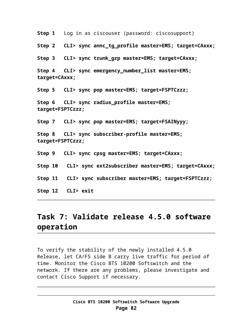
Step 2 Edit and save the ntp.conf file to change the peer information. Each machine should be “peer” to other machines in the system.
For an example:
If the local hostname is secems99, then the ntp.conf should have the following set up:
# peer all other hosts in the same BTSpeer secca99 minpoll 4 maxpoll 8peer prica99 minpoll 4 maxpoll 8peer priems99 minpoll 4 maxpoll 8
Step 3 Restart xntp daemon:
<hostname># /etc/rc2.d/S79xntp stop
<hostname># /etc/rc2.d/S79xntp start
From EMS side A
Step 1 sftp ntp.conf file from CA/FS side B:
<hostname># sftp <CA/FS side B hostname>
sftp> get /opt/BTSxntp/etc/ntp.conf /opt/BTSxntp/etc/ntp.confsftp> quit
Step 2 Edit and save the ntp.conf file to change the peer information. Each machine should be “peer” to other machines in the system.
For an example:
If the local hostname is priems99, then the ntp.conf should have the following set up:
# peer all other hosts in the same BTSpeer secca99 minpoll 4 maxpoll 8peer prica99 minpoll 4 maxpoll 8peer secems99 minpoll 4 maxpoll 8
Step 3 Restart xntp daemon:
<hostname># /etc/rc2.d/S79xntp stop
Cisco BTS 10200 Softswitch Software UpgradePage 82

<hostname># /etc/rc2.d/S79xntp start
Task 3: Remove BTS (3.5.4) linksets
Remove BTS (3.5.4) linksets from the STP-BTS combined linkset.
Task 4: Provisioning new features
From EMS side A
Add new announcements
Step 1 The new announcements should already been prepared in Chapter 3. Please follow steps specified in Appendix J to place the new announcements to appropriate Media Gateways.
Associate announcements
Step 1 If there is NO CLI script prepared, please follow steps specified in Appendix K and skip over Step 2.
Step 2 If there are CLI scripts prepared, log in to the Network File Server where the pre-prepared script resides. SFTP the script to EMS side A log in as CLI user and put script under /opt/ems/ftp/deposit directory.
Wait for the batch process to pick up the script from /opt/ems/ftp/deposit directory and provision it into the system.
Keep running “ls” command from /opt/ems/ftp/deposit directory and till the file is gone
<hostname># cd /opt/ems/report <hostname># egrep Failed:0 <filename>.html
Cisco BTS 10200 Softswitch Software UpgradePage 83

Verify the system returns an output. If there is no output returned, please check for errors in the report file.
Create new features
Step 1 If there is NO CLI script prepared, please follow steps specified in Appendix L and skip over Step 2.
Step 2 If there are CLI scripts prepared, log in to the Network File Server where the pre-prepared script resides. SFTP the script to EMS side A log in as CLI user and put script under /opt/ems/ftp/deposit directory.
Wait for the batch process to pick up the script from /opt/ems/ftp/deposit directory and provision it into the system.
Keep running “ls” command from /opt/ems/ftp/deposit directory and till the file is gone
<hostname># cd /opt/ems/report <hostname># egrep Failed:0 <filename>.html Verify the system returns an output. If there is no output returned, please
check for errors in the report file.
Update existing features
Step 1 If there is NO CLI script prepared, please follow steps specified in Appendix M and skip over Step 2.
Step 2 If there are CLI scripts prepared, log in to the Network File Server where the pre-prepared script resides. SFTP the script to EMS side A log in as CLI user and put script under /opt/ems/ftp/deposit directory.
Wait for the batch process to pick up the script from /opt/ems/ftp/deposit directory and provision it into the system.
Keep running “ls” command from /opt/ems/ftp/deposit directory and till the file is gone
<hostname># cd /opt/ems/report <hostname># egrep Failed:0 <filename>.html Verify the system returns an output. If there is no output returned, please
check for errors in the report file.
Cisco BTS 10200 Softswitch Software UpgradePage 84

Task 5: Restore platform.cfg with logical IPs
From EMS side A
Step 1 log in as root
Step 2 <hostname># cd /opt/Build/btsauto
Step 3 <hostname># restore_platform_cfg.exp
Please enter the password for root when prompted The program will perform the task and should terminate without any error.
Task 6: Enable disk mirroring
Please follow steps in the Appendix X to enable disk mirroring on each machine in the BTS system.
Cisco BTS 10200 Softswitch Software UpgradePage 85

Appendix ACheck System StatusThe purpose of this procedure is to verify the system is running in NORMAL mode, with the side A systems in ACTIVE state and the side B systems in STANDBY state.
Note In the commands below, "xxx", "yyy" or "zzz" is the instance for the process on your system, and DomainName is your system domain name.
From Active EMS side A
Step 1 Log in as CLI user.
Step 2 CLI> status system;
For 3.5.x System response:
Checking Call Agent status ... Checking Feature Server status ... Checking Billing Server status ... Checking Billing MySQL status ... Checking Element Manager status ... Checking EMS MySQL status ... Checking ORACLE status ...
Reply : Success:
CALL AGENT STATUS IS... ->
APPLICATION INSTANCE -> Call Agent [CA146]PRIMARY STATUS -> ACTIVE_NORMALSECONDARY STATUS -> STANDBY_NORMAL
FEATURE SERVER STATUS IS... ->
APPLICATION INSTANCE -> Feature Server [FS235]PRIMARY STATUS -> ACTIVE_NORMAL
Cisco BTS 10200 Softswitch Software UpgradePage 86

SECONDARY STATUS -> STANDBY_NORMAL
FEATURE SERVER STATUS IS... ->
APPLICATION INSTANCE -> Feature Server [FS205]PRIMARY STATUS -> ACTIVE_NORMALSECONDARY STATUS -> STANDBY_NORMAL
BILLING SERVER STATUS IS... ->
APPLICATION INSTANCE -> Bulk Data Management Server [BDMS1]PRIMARY STATUS -> ACTIVE_NORMALSECONDARY STATUS -> STANDBY_NORMAL
BILLING MYSQL STATUS IS... -> Daemon is running!
ELEMENT MANAGER STATUS IS... ->
APPLICATION INSTANCE -> Element Manager [EM1]PRIMARY STATUS -> ACTIVE_NORMALSECONDARY STATUS -> STANDBY_NORMAL
EMS MYSQL STATUS IS ... -> Daemon is running!
ORACLE STATUS IS... -> Daemon is running!
For 4.5.x System response:
Checking Call Agent status ... Checking Feature Server status ... Checking Billing Server status ... Checking Billing Oracle status ... Checking Element Manager status ... Checking EMS MySQL status ... Checking ORACLE status ...
CALL AGENT STATUS IS... ->
APPLICATION INSTANCE -> Call Agent [CA146]PRIMARY STATUS -> ACTIVESECONDARY STATUS -> STANDBY
Cisco BTS 10200 Softswitch Software UpgradePage 87

FEATURE SERVER STATUS IS... ->
APPLICATION INSTANCE -> Feature Server [FSPTC235]PRIMARY STATUS -> ACTIVESECONDARY STATUS -> STANDBY
FEATURE SERVER STATUS IS... ->
APPLICATION INSTANCE -> Feature Server [FSAIN205]PRIMARY STATUS -> ACTIVESECONDARY STATUS -> STANDBY
BILLING SERVER STATUS IS... ->
APPLICATION INSTANCE -> Bulk Data Management Server [BDMS01]PRIMARY STATUS -> ACTIVESECONDARY STATUS -> STANDBY
BILLING ORACLE STATUS IS... -> Daemon is running!
ELEMENT MANAGER STATUS IS... ->
APPLICATION INSTANCE -> Element Manager [EM01]PRIMARY STATUS -> ACTIVESECONDARY STATUS -> STANDBY
EMS MYSQL STATUS IS ... -> Daemon is running!
ORACLE STATUS IS... -> Daemon is running!
Reply : Success:
Cisco BTS 10200 Softswitch Software UpgradePage 88
Appendix BCheck Call ProcessingThis procedure verifies that call processing is functioning without error. The billing record verification is accomplished by making a sample phone call and verify the billing record is collected correctly.
From EMS side A
Step 1 Log in as CLI user.
Step 2 Make a new phone call on the system. Verify that you have two-way voice communication. Then hang up both phones.
Step 3 CLI> report billing-record tail=1;
..CALLTYPE=TOLLSIGSTARTTIME=2004-05-03 17:05:21SIGSTOPTIME=2004-05-03 17:05:35CALLELAPSEDTIME=00:00:00INTERCONNECTELAPSEDTIME=00:00:00ORIGNUMBER=4692551015TERMNUMBER=4692551016CHARGENUMBER=4692551015DIALEDDIGITS=9 4692551016# 5241ACCOUNTCODE=5241CALLTERMINATIONCAUSE=NORMAL_CALL_CLEARINGORIGSIGNALINGTYPE=0TERMSIGNALINGTYPE=0ORIGTRUNKNUMBER=0TERMTRUNKNUMBER=0OUTGOINGTRUNKNUMBER=0ORIGCIRCUITID=0TERMCIRCUITID=0ORIGQOSTIME=2004-05-03 17:05:35ORIGQOSPACKETSSENT=0ORIGQOSPACKETSRECD=7040877
Cisco BTS 10200 Softswitch Software UpgradePage 89

ORIGQOSOCTETSSENT=0ORIGQOSOCTETSRECD=1868853041ORIGQOSPACKETSLOST=805306368ORIGQOSJITTER=0ORIGQOSAVGLATENCY=0TERMQOSTIME=2004-05-03 17:05:35TERMQOSPACKETSSENT=0TERMQOSPACKETSRECD=7040877TERMQOSOCTETSSENT=0TERMQOSOCTETSRECD=1868853041TERMQOSPACKETSLOST=805306368TERMQOSJITTER=0TERMQOSAVGLATENCY=0PACKETIZATIONTIME=0SILENCESUPPRESSION=1ECHOCANCELLATION=0CODECTYPE=PCMUCONNECTIONTYPE=IPOPERATORINVOLVED=0CASUALCALL=0INTERSTATEINDICATOR=0OVERALLCORRELATIONID=CA14633TIMERINDICATOR=0RECORDTYPE=NORMAL RECORDCALLAGENTID=CA146ORIGPOPTIMEZONE=CDTORIGTYPE=ON NETTERMTYPE=ON NETNASERRORCODE=0NASDLCXREASON=0ORIGPOPID=69TERMPOPID=69TERMPOPTIMEZONE=CDTDIALPLANID=cdp1CALLINGPARTYCATEGORY=Ordinary SubscriberCALLEDPARTYINDICATOR=No IndicationCALLEDPARTYPORTEDIN=NoCALLINGPARTYPORTEDIN=NoBILLINGRATEINDICATOR=NoneORIGENDPOINTADDR=c2421-227-142.ipclab.cisco.com
Reply : Success: Entry 1 of 1 returned from host: priems08
Step 4 Verify that the attributes in the CDR match the call just made.
Cisco BTS 10200 Softswitch Software UpgradePage 90

Appendix CCheck Provisioning and Database
From EMS side A
The purpose of this procedure is to verify that provisioning is functioning without error. The following commands will add a "dummy" carrier then delete it.
Step 1 Log in as CLI user.
Step 2 CLI> add carrier id=8080;
Step 3 CLI> show carrier id=8080;
Step 4 CLI> delete carrier id=8080;
Step 5 CLI> show carrier id=8080;
Verify message is: Database is void of entries.
Check transaction queue
In this task, you will verify that the OAMP transaction queue status. The queue should be empty.
Step 1 CLI> show transaction-queue;
Verify there is no entry shown. You should get following reply back:
Reply : Success: Database is void of entries.
If the queue is not empty, wait for the queue to empty. If the problem persists, contact Cisco Support.
Step 2 CLI>exit
Cisco BTS 10200 Softswitch Software UpgradePage 91

Perform database audit
In this task, you will perform a full database audit and correct any errors, if necessary.
Step 1 CLI> audit database type=full;
Step 2 Check the audit report and verify there is no discrepancy or errors. If errors are found, please try to correct them. If you are unable to correct, please contact Cisco Support.
Cisco BTS 10200 Softswitch Software UpgradePage 92

Appendix DCheck Alarm Status The purpose of this procedure is to verify that there are no outstanding major/critical alarms.
From EMS side A
Step 1 Log in as CLI user.
Step 2 CLI> show alarm
The system responds with all current alarms, which must be verified or cleared before proceeding with next step.
Tip Use the following command information for reference material ONLY.
Step 3 To monitor system alarm continuously.
CLI> subscribe alarm-report severity=all; type=all;
Valid severity: MINOR, MAJOR, CRITICAL, ALL Valid types: CALLP, CONFIG, DATABASE, MAINTENANCE, OSS, SECURITY, SIGNALING, STATISTICS, BILLING, ALL, SYSTEM, AUDIT
Step 4 System will display alarms if alarm is reported.
<------------------- START ALARM REPORT -------------------->TIMESTAMP: 20040503174759DESCRIPTION: General MGCP Signaling Error between MGW and CA.TYPE & NUMBER: SIGNALING (79)SEVERITY: MAJORALARM-STATUS: OFFORIGIN: MGA.PRIMARY.CA146
Cisco BTS 10200 Softswitch Software UpgradePage 93

COMPONENT-ID: nullENTITY NAME: S0/DS1-0/[email protected]:5555GENERAL CONTEXT: MGW_TGWSPECIFC CONTEXT: NAFAILURE CONTEXT: NA<------------------- END ALARM REPORT ---------------------->
Step 5 To stop monitoring system alarm.
CLI> unsubscribe alarm-report severity=all; type=all;
Step 6 CLI> exit
Cisco BTS 10200 Softswitch Software UpgradePage 94

Appendix ECheck Oracle Database Replication and Error CorrectionPerform the following steps on the Active EMS side A to check the Oracle database and replication status.
Check Oracle DB replication status
From EMS side A
Step 1 Log in as root.
Step 2 Log in as oracle.
<hostname># su – oracle
Step 3 Enter the command to check replication status and compare contents of tables on the side A and side B EMS databases:
<hostname>$ dbadm –C rep
Step 4 Verify that “Deferror is empty?” is “YES”.
OPTICAL1::Deftrandest is empty? YESOPTICAL1::dba_repcatlog is empty? YESOPTICAL1::Deferror is empty? YES Make sure it is “YES”OPTICAL1::Deftran is empty? YESOPTICAL1::Has no broken job? YESOPTICAL1::JQ Lock is empty? YES
OPTICAL2::Deftrandest is empty? YESOPTICAL2::dba_repcatlog is empty? YESOPTICAL2::Deferror is empty? YES Make sure it is “YES”OPTICAL2::Deftran is empty? YESOPTICAL2::Has no broken job? YESOPTICAL2::JQ Lock is empty? YES
Cisco BTS 10200 Softswitch Software UpgradePage 95

Step 5 If the “Deferror is empty?” is “NO”, please try to correct the error using steps in “Correct replication error” below. If you are unable to clear the error or if any of the individual steps fails, please contact Cisco Support.
Correct replication error
Note You must run the following steps on standby EMS side B first, then on active EMS side A.
From EMS Side B
Step 1 Log in as root
Step 2 <hostname># su – oracle
Step 3 <hostname>$ dbadm –C db
Step 4 For each table that is out of sync, please run the following step:
<hostname>$ dbadm -A copy -o <OWNER> -t <TABEL NAME>
Enter “y” to continue Please contact Cisco Support if the above command fails.
Step 5 <hostname>$ dbadm –A truncate_deferror
Enter “y” to continue
From EMS Side A
Step 1 <hostname>$ dbadm –A truncate_deferror
Enter “y” to continue
Step 2 Re-verify that “Deferror is empty?” is “YES” and none of tables is out of sync.
<hostname>$dbadm –C db
Cisco BTS 10200 Softswitch Software UpgradePage 96

OPTICAL1::Deftrandest is empty? YESOPTICAL1::dba_repcatlog is empty? YESOPTICAL1::Deferror is empty? YES Make sure it is “YES”OPTICAL1::Deftran is empty? YESOPTICAL1::Has no broken job? YESOPTICAL1::JQ Lock is empty? YES
OPTICAL2::Deftrandest is empty? YESOPTICAL2::dba_repcatlog is empty? YESOPTICAL2::Deferror is empty? YES Make sure it is “YES”OPTICAL2::Deftran is empty? YESOPTICAL2::Has no broken job? YESOPTICAL2::JQ Lock is empty? YES
Cisco BTS 10200 Softswitch Software UpgradePage 97

Appendix FFlash Archive Steps
Task 1: Ensure side A systems are ACTIVE
In this task, you will ensure that the EMS side A applications are active.
Step 1 Log in as root to ACTIVE EMS
Step 2 Log in as CLI user
Step 3 CLI> control call-agent id=CAxxx; target-state=active-standby;
Step 4 CLI> control feature-server id=FSPTCzzz; target-state=active-standby;
Step 5 CLI> control feature-server id=FSAINyyy; target-state=active-standby;
Step 6 CLI> control bdms id=BDMS01; target-state=active-standby;
Step 7 CLI> control element-manager id=EM01; target-state=active-standby;
Step 8 CLI> status system;
Verify applications on Side A are in ACTIVE state. Verify applications on Side B are in STANDBY state. Verify Oracle DB is in service
Step 9 CLI>exit
Task 2: Perform a full database audit
In this task, you will go to EMS side A and perform a full database audit and correct errors, if there are any. Contact Cisco Support if errors cannot be fixed.
Cisco BTS 10200 Softswitch Software UpgradePage 98

From EMS Side A
Step 1 Log in as CLI user
Step 2 CLI> audit database type=full;
Step 3 Check the audit report and verify there is no discrepancy or errors found. If errors are found, try to correct the errors. If you are unable to make the correction, contact Cisco Support.
Task 3: Perform shared memory integrity check
In this task, you will perform shared memory integrity check to detect any potential data problems.
From CA/FS side A
Step 1 Log in as root
Step 2 <hostname># cd /opt/OptiCall/CAxxx/bin
Step 3 <hostname># ca_tiat data
Step 4 Press “Enter” to continue
The result should be identical to the following:
All tables are OK.
For detail, see ca_tiat.out
If the result does NOT show “All tables are OK”, contact Cisco Support.
Step 5 <hostname># cd /opt/OptiCall/FSPTCzzz/bin
Step 6 <hostname># potsctx_tiat data
Step 7 Press “Enter” to continue
The result should be identical to the following:
Cisco BTS 10200 Softswitch Software UpgradePage 99
All tables are OK.
For detail, see potsctx_tiat.out
If the result does NOT show “All tables are OK”, contact Cisco Support.
Step 8 <hostname># cd /opt/OptiCall/FSAINyyy/bin
Step 9 <hostname># ain_tiat data
Step 10 Press “Enter” to continue
The result should be identical to the following:
All tables are OK.
For detail, see ain_tiat.out
If the result does NOT show “All tables are OK”, contact Cisco Support.
From CA/FS side B
Step 1 Log in as root
Step 2 <hostname># cd /opt/OptiCall/CAxxx/bin
Step 3 <hostname># ca_tiat data
Step 4 Press “Enter” to continue
The result should be identical to the following:
All tables are OK.
For detail, see ca_tiat.out
If the result does NOT show “All tables are OK”, contact Cisco Support.
Step 5 <hostname># cd /opt/OptiCall/FSPTCzzz/bin
Step 6 <hostname># potsctx_tiat data
Step 7 Press “Enter” to continue
Cisco BTS 10200 Softswitch Software UpgradePage 100

The result should be identical to the following:
All tables are OK.
For detail, see potsctx_tiat.out
If the result does NOT show “All tables are OK”, contact Cisco Support.
Step 8 <hostname># cd /opt/OptiCall/FSAINyyy/bin
Step 9 <hostname># ain_tiat data
Step 10 Press “Enter” to continue
The result should be identical to the following:
All tables are OK.
For detail, see ain_tiat.out
If the result does NOT show “All tables are OK”, contact Cisco Support.
Task 4: Perform flash archive on EMS side B
In this task, you will perform a flash archive on EMS side B to save a copy of OS and applications to a remote server. This process takes about 1 hour.
Note Perform Task 4: Perform Flash Archive on EMS Side B and Task 5: Perform Flash Archive on CA/FS Side B in parallel.
From EMS side B
Step 1 Log in as root
Step 2 <hostname># svcadm disable system/cron
Step 3 <hostname># ps -ef | grep cron
Verify no result is returned, which means cron daemon is no longer running.
Step 4 <hostname># cd /etc/rc3.d
Cisco BTS 10200 Softswitch Software UpgradePage 101

Step 5 <hostname># mv S99platform _S99platform
Step 6 <hostname># platform stop all
Step 7 <hostname># nodestat
Verify applications are out of service.
Step 8 <hostname># \rm –rf /opt/Build
Step 9 <hostname># \rm –rf /opt/8_rec
Step 10 <hostname># \rm –rf /opt/.upgrade
Step 11 Remove all directories and files that are no longer needed such as core files, patch directories.
Step 12 <hostname># mv /bin/date /bin/date.orig
Step 13 <hostname># mv /bin/.date /bin/date
Step 14 <hostname># tar –cvf - /opt/* | gzip –c > /opt/<hostname_release>.tar.gz
Where: hostname_release is the tar file name.
Example: tar –cvf - /opt/* | gzip –c > /opt/secems10_4.5.0V00.tar.gz
Step 15 <hostname># flarcreate -n <archive name> -x /opt -c /opt/<file name>
Where: archive name is the archive identification.
Example: flarcreate -n CCPU-EMS –x /opt -c /opt/secems10_4.5.0V00.archive
Step 16 SFTP the archive to an NFS server to be used later.
<hostname># cd /opt <hostname># sftp <nfs server name>
sftp> bin
sftp> cd <target directory>
sftp> put <archive file name>
sftp> put <opt tar file name>
Cisco BTS 10200 Softswitch Software UpgradePage 102

sftp> bye
Step 17 <hostname># mv /bin/date /bin/.date
Step 18 <hostname># mv /bin/date.orig /bin/date
Step 19 <hostname># svcadm enable system/cron
Step 20 <hostname># ps -ef | grep cron
Verify cron daemon is running.
Step 21 <hostname># cd /etc/rc3.d
Step 22 <hostname># mv _S99platform S99platform
Step 23 <hostname># platform start
Step 24 <hostname># nodestat
Verify EM01 is in STANDBY. Verify BS01 is in STANDBY.
Verify Oracle and Billing DBs are in service.
Task 5: Perform flash archive on CA/FS side B
In this task, you will perform a flash archive on CA/FS side B to save a copy of OS and applications to a remote server. This process takes about 1 hour.
Note Perform this task in parallel with Task 4: Perform Flash Archive on EMS Side B.
From CA/FS side B
Step 1 Log in as root
Step 2 <hostname># svcadm disable system/cron
Step 3 <hostname># ps -ef | grep cron
Verify no result is returned, which means cron daemon is no longer running
Cisco BTS 10200 Softswitch Software UpgradePage 103

Step 4 <hostname># cd /etc/rc3.d
Step 5 <hostname># mv S99platform _S99platform
Step 6 <hostname># platform stop all
Step 7 <hostname># nodestat
Verify applications are out of service.
Step 8 <hostname># \rm –rf /opt/Build
Step 9 <hostname># \rm –rf /opt/8_rec
Step 10 <hostname># \rm –rf /opt/.upgrade
Step 11 Remove all directories and files that are no longer needed such as core files, patch directories.
Step 12 <hostname># mv /bin/date /bin/date.orig
Step 13 <hostname># mv /bin/.date /bin/date
Step 14 <hostname># tar –cvf - /opt/* | gzip –c > /opt/<hostname_release>.tar.gz
Where: hostname_release is the tar file name.
Example: tar –cvf - /opt/* | gzip –c > /opt/secca10_4.5.0V00.tar.gz
Step 15 <hostname># flarcreate -n <archive name> -x /opt -c /opt/<file name>
Where: archive name is the archive identification.
Example: flarcreate -n CCPU-CA –x /opt -c /opt/secca10_4.5.0V00.archive
Step 16 SFTP the archive to an NFS server to be used later.
<hostname># cd /opt <hostname># sftp <nfs server name>
sftp> bin
sftp> cd <target directory>
sftp> put <archive file name>
Cisco BTS 10200 Softswitch Software UpgradePage 104
sftp> put <opt tar file name>
sftp> bye
Step 17 <hostname># mv /bin/date /bin/.date
Step 19 <hostname># mv /bin/date.orig /bin/date
Step 20 <hostname># svcadm enable system/cron
Step 21 <hostname># ps -ef | grep cron
Verify cron daemon is running.
Step 22 <hostname># cd /etc/rc3.d
Step 23 <hostname># mv _S99platform S99platform
Step 24 <hostname># platform start
Step 25 <hostname># nodestat
Verify CAxxx is in STANDBY. Verify FSAINyyy is in STANDBY.
Verify FSPTCzzz is in STANDBY.
Task 6: Switch activity from side A to side B
In this task, you will switch activity from the side A to the side B.
From EMS side A
Step 1 Log in as CLI user
Step 2 CLI> control call-agent id=CAxxx; target-state=standby-active;
Step 3 CLI> control feature-server id=FSPTCzzz; target-state=standby-active;
Step 4 CLI> control feature-server id=FSAINyyy; target-state=standby-active;
Step 5 CLI> control bdms id=BDMS01; target-state=standby-active;
Cisco BTS 10200 Softswitch Software UpgradePage 105
Step 6 CLI> control element-manager id=EM01; target-state=standby-active;
Step 7 CLI session will terminate when EM01 switchover is successful.
Task 7: Perform flash archive on EMS side A
In this task, you will perform a flash archive on EMS side A to save a copy of the OS and applications to a remote server. This process takes about 1 hour.
Note Perform Task 7: Perform Flash Archive on EMS Side A and Task 8: Perform Flash Archive on CA/FS Side A in parallel.
From EMS side A
Step 1 Log in as root
Step 2 <hostname># svcadm disable system/cron
Step 3 <hostname># ps -ef | grep cron
Verify no result is returned, which means cron daemon is no longer running.
Step 4 <hostname># cd /etc/rc3.d
Step 5 <hostname># mv S99platform _S99platform
Step 6 <hostname># platform stop all
Step 7 <hostname># nodestat
Verify applications are out of service.
Step 8 <hostname># \rm –rf /opt/Build
Step 9 <hostname># \rm –rf /opt/8_rec
Step 10 <hostname># \rm –rf /opt/.upgrade
Step 11 Remove all directories and files that are no longer needed such as core files, patch directories.
Step 12 <hostname># mv /bin/date /bin/date.orig
Cisco BTS 10200 Softswitch Software UpgradePage 106

Step 13 <hostname># mv /bin/.date /bin/date
Step 14 <hostname># tar –cvf - /opt/* | gzip –c > /opt/<hostname_release>.tar.gz
Where: hostname_release is the tar file name.
Example: tar –cvf - /opt/* | gzip –c > /opt/priems10_4.5.0V00.tar.gz
Step 15 <hostname># flarcreate -n <archive name> -x /opt -c /opt/<file name>
Where: archive name is the archive identification.
Example: flarcreate -n CCPU-EMS –x /opt -c /opt/priems10_4.5.0V00.archive
Step 16 SFTP the archive to an NFS server to be used later.
<hostname># cd /opt <hostname># sftp <nfs server name>
sftp> bin
sftp> cd <target directory>
sftp> put <archive file name>
sftp> put <opt tar file name>
sftp> bye
Step 17 <hostname># mv /bin/date /bin/.date
Step 18 <hostname># mv /bin/date.orig /bin/date
Step 19 <hostname># svcadm enable system/cron
Step 20 <hostname># ps -ef | grep cron
Verify cron daemon is running.
Step 21 <hostname># cd /etc/rc3.d
Step 22 <hostname># mv _S99platform S99platform
Step 23 <hostname># platform start
Step 24 <hostname># nodestat
Cisco BTS 10200 Softswitch Software UpgradePage 107

Verify EM01 is in STANDBY. Verify BS01 is in STANDBY.
Verify Oracle and Billing DBs are in service.
Task 8: Perform flash archive on CA/FS side A
In this task, you will perform flash archive on CA/FS side A to save a copy of OS and applications to a remote server. This process takes about 1 hour.
Note Perform this task in parallel with Task 7: Perform Flash Archive on EMS Side A.
From CA/FS side A
Step 1 Log in as root
Step 2 <hostname># svcadm disable system/cron
Step 3 <hostname># ps -ef | grep cron
Verify no result is returned, which means cron daemon is no longer running
Step 4 <hostname># cd /etc/rc3.d
Step 5 <hostname># mv S99platform _S99platform
Step 6 <hostname># platform stop all
Step 7 <hostname># nodestat
Verify applications are out of service.
Step 8 <hostname># \rm –rf /opt/Build
Step 9 <hostname># \rm –rf /opt/8_rec
Step 10 <hostname>#\rm –rf /opt/.upgrade
Step 11 Remove all directories and files that are no longer needed such as core files, patch directories.
Step 12 <hostname># mv /bin/date /bin/date.orig
Cisco BTS 10200 Softswitch Software UpgradePage 108

Step 13 <hostname># mv /bin/.date /bin/date
Step 14 <hostname># tar –cvf - /opt/* | gzip –c > /opt/<hostname_release>.tar.gz
Where: hostname_release is the tar file name.
Example: tar –cvf - /opt/* | gzip –c > /opt/prica10_4.5.0V00.tar.gz
Step 15 <hostname># flarcreate -n <archive name> -x /opt -c /opt/<file name>
Where: archive name is the archive identification.
Example: flarcreate -n CCPU-CA –x /opt -c /opt/prica10_4.5.0V00.archive
Step 16 SFTP the archive to an NFS server to be used later.
<hostname># cd /opt <hostname># sftp <nfs server name>
sftp> bin
sftp> cd <target directory>
sftp> put <archive file name>
sftp> put <opt tar file name>
sftp> bye
Step 17 <hostname># mv /bin/date /bin/.date
Step 18 <hostname># mv /bin/date.orig /bin/date
Step 19 <hostname># svcadm enable system/cron
Step 20 <hostname># ps -ef | grep cron
Verify cron daemon is running.
Step 21 <hostname># cd /etc/rc3.d
Step 22 <hostname># mv _S99platform S99platform
Step 23 <hostname># platform start
Step 24 <hostname># nodestat
Cisco BTS 10200 Softswitch Software UpgradePage 109

Verify CAxxx is in STANDBY. Verify FSAINyyy is in STANDBY.
Verify FSPTCzzz is in STANDBY.
Task 9: Restore the system to normal mode
In this task, you will release the forced switch.
From EMS side B
Step 1 Log in as CLI user
Step 2 CLI> control call-agent id=CAxxx; target-state=active-standby;
Step 3 CLI> control feature-server id=FSPTCyyy; target-state=active-standby;
Step 4 CLI> control feature-server id=FSAINzzz; target-state=active-standby;
Step 5 CLI> control bdms id=BDMS01; target-state=active-standby;
Step 6 CLI> control element-manager id=EM01; target-state=active-standby;
Step 7 CLI session will terminate when the EM01 switchover is successful.
This completes the flash archive process.
Cisco BTS 10200 Softswitch Software UpgradePage 110

Appendix GBackout Procedure for Side B Systems
Introduction
This procedure allows you to back out of the upgrade procedure if any verification checks (in "Verify Call/System Status" section) failed. This procedure is intended for the scenario in which the side B systems have been upgraded to the new load, while the side A systems are still at the previous load. The procedure will back out the side B systems to the previous load.
This backout procedure will:
Restore the side A systems to active mode without making any changes to it Revert to the previous application load on the side B systems Restart the side B systems in standby mode Verify that the system is functioning properly with the previous load
Note In addition to performing this backout procedure, you should contact Cisco Support when you are ready to retry the upgrade procedure.
The flow for this procedure is shown in Figure F-1.
Cisco BTS 10200 Softswitch Software UpgradePage 111

Figure F-1 Flow of Backout Procedure— Side B Only
Task 1: Remove SCCP configuration from ITPs
Please remove all SCCP settings from ITPS by executing IOS commands. The IOS command file should already be prepared in Chapter 2, Task 3. If not, please remove the configuration manually.
Task 2: Restore OMNI SS7 link(s) and linkset from ITP
Cisco BTS 10200 Softswitch Software UpgradePage 112
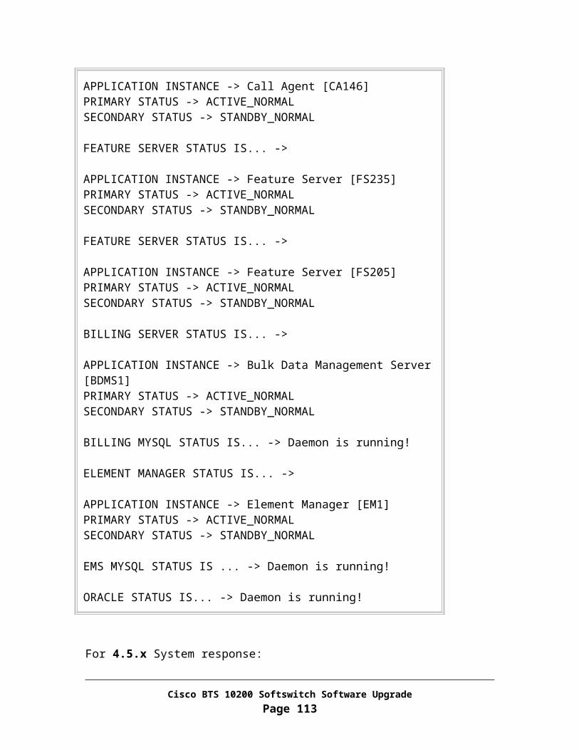
Restore SS7 link(s) and linkset before switching over the application platforms from release 4.5.0 Primary Side A to release 3.5.4 Secondary Side B. Sample IOS command is given below:
cs7 linkset to_bts10200 7.7.7description linkset to bts10200link 0 Serial1/1/5:0link 1 Serial1/1/6:0no shut
Task 3: Control SS7 trunk groups out of service on release 4.5.0
From EMS side B
Step 1 If there is NO CLI script prepared, please follow steps specified in Appendix Q and then continue on Step 3.
Step 2 If there are CLI scripts prepared, log in to the Network File Server where the pre-prepared script resides. SFTP the script to EMS side B log in as CLI user and put script under /opt/ems/ftp/deposit directory.
Wait for the batch process to pick up the script from /opt/ems/ftp/deposit directory and provision it into the system.
Keep running “ls” command from /opt/ems/ftp/deposit directory and till the file is gone
<hostname># cd /opt/ems/report <hostname># egrep Failed:0 <filename>.html Verify the system returns an output. If there is no output returned, please
check for errors in the report file.
Step 3 Check the status of each SS7 trunk group – the admin state should be out of service:
Log in as CLI user to EMS side B CLI> status trunk-grp id=<SS7 trunk group ID>;
Cisco BTS 10200 Softswitch Software UpgradePage 113
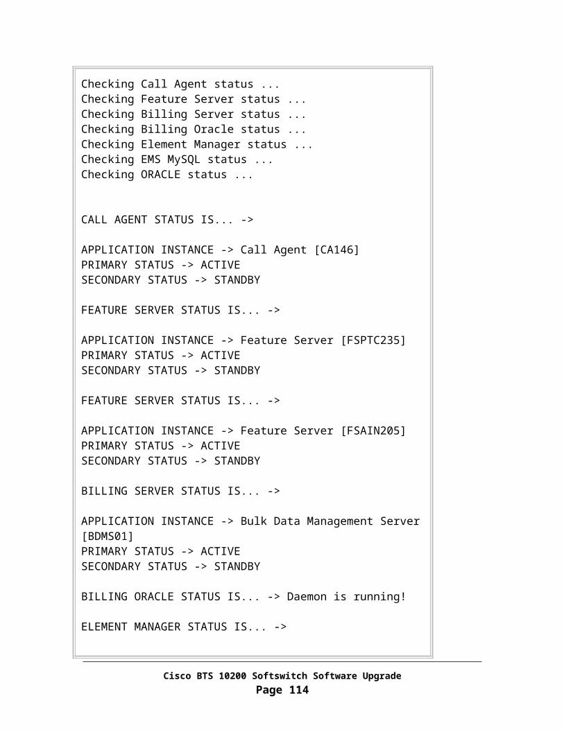
Task 4: Force side A CA/FS to active
This procedure will force the side A systems to forced active state, and the side B systems to forced standby state.
Note In the commands below, "xxx", "yyy" or "zzz" is the instance for the process on your system.
From EMS side B
Step 1 Log in as CLI user.
Step 2 CLI> control call-agent id=CAxxx; target-state=active-standby;
Step 3 CLI> control feature-server id=FSPTCzzz; target-state=active-standby;
Step 4 CLI> control feature-server id=FSAINyyy; target-state=active-standby;
Step 5 CLI> exit
Task 5: SFTP billing records to a mediation device
From EMS side B
Step 1 Log in as root
Step 2 <hostname># platform stop
Answer “y” if prompt for terminating the application platform
Step 3 <hostname># cd /opt/bms/ftp/billing
Step 4 <hostname># ls
Step 5 If there are files listed, then SFTP the files to a mediation device on the network and remove the files from the /opt/bms/ftp/billing directory
Cisco BTS 10200 Softswitch Software UpgradePage 114
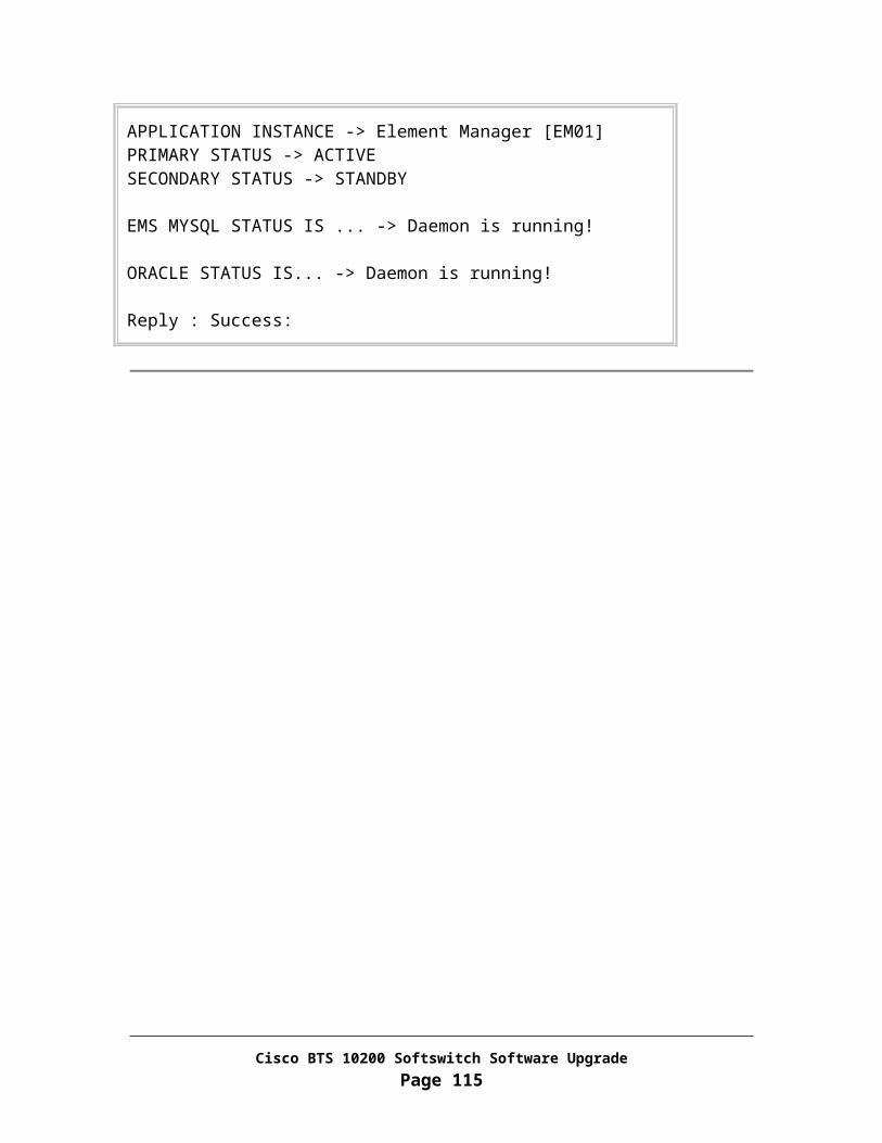
Task 6: Control SS7 links in service
In this task, you will re-activate SS7 links in OMNI to fallback the system back to 3.5.4 release.
From CA/FS side A
Step 1 Log in as root
Step 2 Activate SS7 Links on CA/FS side A.
1. <hostname># termhandler -node a7n1
OMNI [date] #1:actv-slk:slk=< SS7 link on CA/FS side A >; Enter y to continue.
Repeat above two steps for each inactive link
2. OMNI [date] #2:display-slk;
Enter y to continue Verify that the state of each link is ACTIVE.
3. OMNI[date]#3:quit
Task 7: Control SS7 trunk groups in service on release 3.5.4 side
From EMS side A
Step 1 If there is NO CLI script prepared, please follow steps specified in Appendix R and then continue on Step 3.
Step 2 If there are CLI scripts prepared, log in to the Network File Server where the pre-prepared script resides. SFTP the script to EMS side A log in as CLI user and put script under /opt/ems/ftp/deposit directory.
Cisco BTS 10200 Softswitch Software UpgradePage 115

Wait for the batch process to pick up the script from /opt/ems/ftp/deposit directory and provision it into the system.
Keep running “ls” command from /opt/ems/ftp/deposit directory and till the file is gone
<hostname># cd /opt/ems/report <hostname># egrep Failed:0 <filename>.html Verify the system returns an output. If there is no output returned, please
check for errors in the report file.
Step 3 Check the status of each SS7 trunk group – the admin state should be in service:
Log in as CLI user to EMS side B CLI> status trunk-grp id=<SS7 trunk group ID>;
Task 8: Bounce SS7 trunks on release 3.5.4
From EMS side A
Step 1 If there is NO CLI script prepared, please follow steps specified in Appendix Y and then continue on Step 3.
Step 2 If there are CLI scripts prepared, log in to the Network File Server where the pre-prepared script resides. SFTP the script to EMS side A log in as CLI user and put script under /opt/ems/ftp/deposit directory.
Wait for the batch process to pick up the script from /opt/ems/ftp/deposit directory and provision it into the system.
Keep running “ls” command from /opt/ems/ftp/deposit directory and till the file is gone
<hostname># cd /opt/ems/report <hostname># egrep Failed:0 <filename>.html Verify the system returns an output. If there is no output returned, please
check for errors in the report file.
Step 3 Check the status of each SS7 trunk-termination – The OPER state should be in service:
Log in as CLI user to EMS side B CLI> status trunk-termination id=<SS7 trunk group ID>; cic=all;
Cisco BTS 10200 Softswitch Software UpgradePage 116

Task 9: Sync DB usage
From EMS side A
In this task, you will sync db-usage between two releases.
Step 1 Log in as root
Step 2 <hostname># su – oracle
Step 3 <hostname>$ java dba.adm.DBUsage –sync
Verify Number of tables “unable-to-sync” is 0.
Step 4 <hostname>$ exit
Task 10: Stop applications and shutdown side B systems
From EMS side B
Step 1 Log in as root.
Step 2 <hostname># platform stop all
Step 3 <hostname># sync; sync
Step 4 <hostname># shutdown –i5 –g0 –y
From CA/FS side B
Step 1 Log in as root.
Step 2 <hostname># platform stop all
Step 3 <hostname># sync; sync
Cisco BTS 10200 Softswitch Software UpgradePage 117

Step 4 <hostname># shutdown –i5 –g0 –y
Task 11: Restore side B systems to the old release
From CA/FS side B
Step 1 Power off the machine
Step 2 Remove disk0 from slot 0 off the machine
Step 3 Place disk labeled “Release 3.5.4 CA/FS side B disk0” in slot 0
Step 4 Power on the machine
For a Netra 1280 machine, please execute the following command from console:
<lom>poweron
For other type of hardware, please use the power button to turn on the power.
Step 5 <hostname># platform start
Step 6 Activate SS7 Links on CA/FS side B.
1. <hostname># termhandler -node a7n1
OMNI [date] #1:actv-slk:slk=< link on CA/FS side B >; Enter y to continue.
Repeat above two steps for each inactive link
2. OMNI [date] #2:display-slk;
Enter y to continue Verify that the state of each link is ACTIVE.
3. OMNI[date]#3:quit
Step 7 <hostname># mv /etc/rc3.d/_S99platform /etc/rc3.d/S99platform
Cisco BTS 10200 Softswitch Software UpgradePage 118
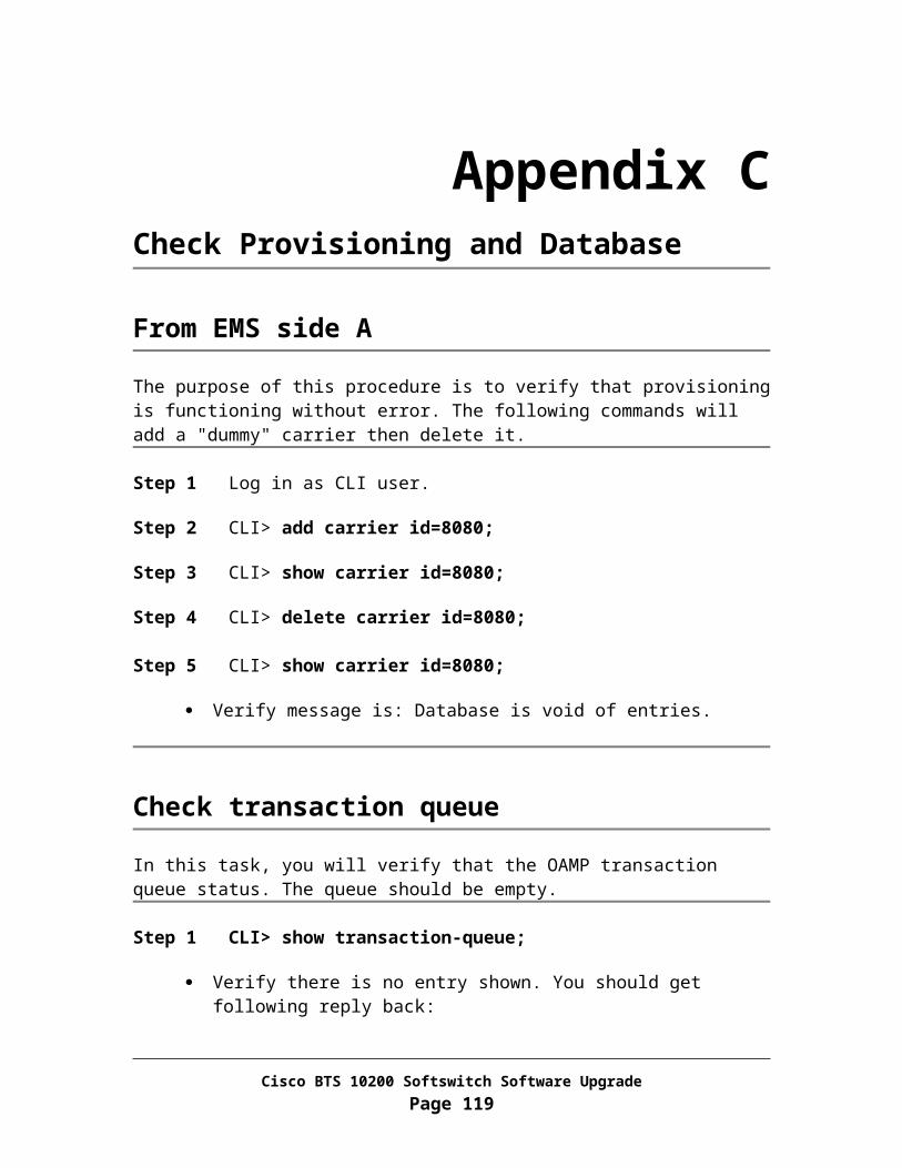
From EMS side B
Step 1 Power off the machine
Step 2 Remove disk0 from slot 0 off the machine
Step 3 Place disk labeled “Release 3.5.4 EMS side B disk0” in slot 0
Step 4 Power on the machine
For a Netra 1280 machine, please execute the following command from console:
<lom>poweron
For other type of hardware, please use the power button to turn on the power.
Step 5 <hostname># platform start
Step 6 <hostname># mv /etc/rc3.d/_S99platform /etc/rc3.d/S99platform
Task 12: Restore EMS mate communication
In this task, you will restore the OMS Hub communication from EMS side A to side B.
From EMS side A
Step 1 Log in as root
Step 2 <hostname># cd /opt/ems/utils
Step 3 <hostname># updMgr.sh –restore_hub
Step 4 <hostname># nodestat
Verify OMS Hub mate port status is established. Verify HUB communication from EMS side A to CA/FS side B is established.
Task 13: Switchover activity to EMS side B
Cisco BTS 10200 Softswitch Software UpgradePage 119
From Active EMS side A
Step 1 Log in as CLI user.
Step 2 CLI> control bdms id=BDMS01; target-state=forced-standby-active;
Step 3 CLI> control element-manager id=EM01; target-state=forced-standby-active;
Step 4 CLI Log in session will be terminated when switchover is completed.
Task 14: Enable Oracle DB replication on EMS side A
From EMS side A
Step 1 Log in as Oracle user:
<hostname># su - oracle
<hostname>$ cd /opt/oracle/admin/utl
Step2 Restore Oracle DB replication:
<hostname>$ rep_toggle –s optical1 –t set_duplex
Answer “y” when promptAnswer “y” again when prompt
Step 3 <hostname>$ exit
Step 4 Terminate applications and all Oracle connections.
<hostname># platform stop all
Step 5 Re-start applications.
<hostname># platform start
Cisco BTS 10200 Softswitch Software UpgradePage 120
Task 15: Synchronize handset provisioning data
From EMS side B
Note In the commands below, "xxx", "yyy" or "zzz" is the instance for the process on your system.
Step 1 Log in as ciscouser (password: ciscosupport)
Step 2 CLI> sync termination master=CAxxx; target=EMS;
Verify the transaction is executed successfully.
Step 3 CLI> sync sc1d master=FSPTCzzz; target=EMS;
Verify the transaction is executed successfully
Step 4 CLI> sync sc2d master=FSPTCzzz; target=EMS;
Verify the transaction is executed successfully
Step 5 CLI> sync sle master=FSPTCzzz; target=EMS;
Verify the transaction is executed successfully
Step 6 CLI> sync subscriber-feature-data master=FSPTCzzz; target=EMS;
Verify the transaction is executed successfully
Step 7 CLI> exit
Task 16: Switchover activity from EMS side B to EMS side A
From EMS side B
Step 1 Log in as CLI user.
Step 2 CLI> control bdms id=BDMS01; target-state=forced-active-standby;
Cisco BTS 10200 Softswitch Software UpgradePage 121

Step 3 CLI> control element-manager id=EM01; target-state=forced-active-standby;
Step 4 CLI Log in session will be terminated when switchover is completed.
Task 17: Restore system to normal mode
From EMS side A
Step 1 Log in as CLI user.
Step 2 CLI> control feature-server id=FSPTCzzz; target-state=normal;
Step 3 CLI> control feature-server id=FSAINyyy; target-state=normal;
Step 4 CLI> control call_agent id=CAxxx; target-state=normal;
Step 5 CLI> control bdms id=BDMS01; target-state=normal;
Step 6 CLI> control element-manager id=EM01; target-state=normal;
Step 7 CLI> exit
Task 18: Verify system status
Verify that the system is operating properly before you leave the site.
Step 1 Verify that the side A systems are in the active state. Use Appendix A for this procedure.
Step 2 Verify that call processing is working without error. Use Appendix B for this procedure.
Step 3 Verify that provisioning is operational from CLI command line, and verify database. Use Appendix C for this procedure.
Step 4 Verify that there are no outstanding major or critical alarms. Use Appendix D for this procedure.
Cisco BTS 10200 Softswitch Software UpgradePage 122

Step 5 Use Appendix E to verify that Oracle database and replication functions are working properly.
Step 6 If you answered NO to any of the above questions (Step 1 through Step 5), Contact Cisco Support for assistance.
Task 19: Change MGCP Domain IP addresses from Domain Name Server
From each Domain Name Server that is serving the BTS 10200, restore the IP addresses for MGCP domain name from 2 physical IPs from primary CA/FS and 2 logical IPs: 2P + 2L back to 2 physical IPs from primary CA/FS and 2 physical IPs from secondary CA/FS: 2P + 2S.
You have completed the side B of Cisco BTS 10200 system fallback process successfully.
Cisco BTS 10200 Softswitch Software UpgradePage 123

Appendix HSystem Backout Procedure
Introduction
This procedure allows you to back out of the upgrade procedure if any verification checks (in "Verify system status" section) failed. This procedure is intended for the scenario in which both the side A and side B systems have been upgraded to the new load. The procedure will back out the entire system to the previous load.
This backout procedure will:
Revert to the previous application load on the side A systems Restart the side A systems and place it in active mode Revert to the previous application load on the side B systems Restart the side B systems and place it in active mode Verify that the system is functioning properly with the previous load
Note In addition to performing this backout procedure, you should contact Cisco Support when you are ready to retry the upgrade procedure.
Task 1: Check MGCP Domain IP addresses from Domain Name Servers
From each Domain Name Server that is serving the upgraded BTS 10200, please make sure the IPs for the MGCP domain name in the DNS database is set to: 2P + 2L.
If not, please make the change accordingly. Then refresh the DNS cache and make sure the new IP addresses are taking affect. To verify the change has taken affect, please log in to both CA/FS machines and perform “nslookup” of the MGCP domain name.
Cisco BTS 10200 Softswitch Software UpgradePage 124

Task 2: Disable Oracle DB replication on EMS side B
From Active EMS
Step 1 Log in as CLI user.
Step 2 CLI> control bdms id=BDMS01; target-state=active-standby;
Step 3 CLI> control element-manager id=EM01; target-state=active-standby;
Step 4 CLI> exit
From EMS side B
Step 1 Log in as Oracle user:
<hostname># su – oracle
<hostname>$ cd /opt/oracle/admin/utl
Step 2 Set Oracle DB to simplex mode:
<hostname>$ rep_toggle –s optical2 –t set_simplex
Answer “y” when promptAnswer “y” again when prompt
Step 3 Exit from Oracle Log in.
<hostname>$ exit
Step 4 Terminate applications.
<hostname># platform stop all
Step 5 Re-start applications to activate DB toggle in simplex mode.
<hostname># platform start
Cisco BTS 10200 Softswitch Software UpgradePage 125
Task 3: Inhibit EMS mate communication
In this task, you will isolate the OMS Hub on EMS side B from talking to CA/FS side A.
From EMS side B
Step 1 Log in as root
Step 2 <hostname># cd /opt/ems/utils
Step 3 <hostname># updMgr.sh –split_hub
Step 4 <hostname># nodestat
Verify there is no HUB communication from EMS side B to CA/FS side A.
Task 4: Force side B systems to active
This procedure will force the side B systems to go active.
Note In the commands below, "xxx", "yyy" or "zzz" is the instance for the process on your system.
From EMS side A
Step 1 Log in as CLI user.
Step 2 CLI> control call-agent id=CAxxx; target-state=standby-active;
Step 3 CLI> control feature-server id=FSPTCzzz; target-state=standby-active;
Step 4 CLI> control feature-server id=FSAINyyy; target-state=standby-active;
Step 5 CLI> control bdms id=BDMS01; target-state=standby-active;
Step 6 CLI> control element-manager id=EM01; target-state=standby-active;
Step 7 CLI session will terminate when the last CLI command completes.
Cisco BTS 10200 Softswitch Software UpgradePage 126

Task 5: SFTP billing records to a mediation device
From EMS side A
Step 1 Log in as root
Step 2 <hostname># cd /opt/bms/ftp/billing
Step 3 <hostname># ls
Step 4 If there are files listed, then SFTP the files to a mediation device on the network and remove the files from the /opt/bms/ftp/billing directory
Task 6: Stop applications
From EMS side A
Step 1 Log in as root.
Step 2 <hostname># platform stop all
Step 3 <hostname># sync; sync
Step 4 <hostname># shutdown –i5 –g0 –y
From CA/FS side A
Step 1 Log in as root.
Step 2 <hostname># platform stop all
Step 3 <hostname># sync; sync
Step 4 <hostname># shutdown –i5 –g0 –y
Cisco BTS 10200 Softswitch Software UpgradePage 127

Task 7: Restore side A systems to the old release
From CA/FS side A
Step 1 Power off the machine
Step 2 Remove disk0 from slot 0 off the machine
Step 3 Place disk labeled “Release 3.5.4 CA/FS side A disk0” in slot 0
Step 4 Power on the machine
For a Netra 1280 machine, please execute the following command from console:
<lom>poweron
For other type of hardware, please use the power button to turn on the power.
Step 5 <hostname># platform start
Step 6 Activate SS7 Links on CA/FS side A.
1. <hostname># termhandler -node a7n1
OMNI [date] #1:actv-slk:slk=< link on CA/FS side A >; Enter y to continue.
Repeat above two steps for each inactive link
2. OMNI [date] #2:display-slk;
Enter y to continue Verify that the state of each link is ACTIVE.
3. OMNI[date]#3:quit
Step 7 <hostname># mv /etc/rc3.d/_S99platform /etc/rc3.d/S99platform
From EMS side A
Cisco BTS 10200 Softswitch Software UpgradePage 128

Step 1 Power off the machine
Step 2 Remove disk0 from slot 0 off the machine
Step 3 Place disk labeled “Release 3.5.5 EMS side A disk0” in slot 0
Step 4 Power on the machine
For a Netra 1280 machine, please execute the following command from console:
<lom>poweron
For other type of hardware, please use the power button to turn on the power.
Step 5 Log in as root.
Step 6 <hostname># /opt/ems/utils/updMgr.sh –split_hub
Step 7 <hostname># /etc/rc2.d/S75cron stop
Step 8 <hostname># platform start –i oracle
Step 9 Log in as Oracle user.
<hostname># su – oracle
<hostname>$ cd /opt/oracle/admin/utl
<hostname>$ rep_toggle –s optical1 –t load_pkg
<hostname>$ rep_toggle –s optical1 –t add_toggle
Step 12 Change Oracle DB to simplex mode:
<hostname>$ rep_toggle –s optical1 –t set_simplex
Answer “y” when prompt Answer “y” again when prompt
Step 13 <hostname>$ exit
Step 14 <hostname># mv /etc/rc3.d/_S99platform /etc/rc3.d/S99platform
Cisco BTS 10200 Softswitch Software UpgradePage 129

Task 8: Stop EMS side B billing application
From EMS side B
Step 1 Log in as root.
Step 2 <hostname># platform stop -i BDMS01
Answer “y” when prompt for confirmation
Task 9: Start EMS side A applications
From EMS side A
Step 1 <hostname># platform start
Step 2 <hostname># /etc/rc2.d/S75cron start
Task 10: To continue fallback process, please follow Appendix G.
You have completed the Cisco BTS 10200 system fallback process successfully
Cisco BTS 10200 Softswitch Software UpgradePage 130

Appendix ICORBA InstallationThis procedure describes how to install the Common Object Request Broker Architecture (CORBA) application on Element Management System (EMS) of the Cisco BTS 10200 Softswitch.
Note This installation process is used for both side A and side B EMS.
Caution This CORBA installation will remove existing CORBA application on EMS machines. Once you have executed this procedure, there is no backout. Do not start this procedure until you have proper authorization. If you have questions, please contact Cisco Support.
Task 1: Open Unix Shell on EMS
Perform these steps to open a Unix shell on EMS.
Step 1 Ensure that your local PC or workstation has connectivity via TCP/IP to communicate with EMS units.
Step 2 Open a Unix shell or a XTerm window.
Note If you are unable to open a Xterm window, please contact you system administrator immediately.
Task 2: Install OpenORB CORBA Application
Remove Installed OpenORB Application
Step 1 Log in as root to EMS
Step 2 Enter the following command to remove the existing OpenORB package:
Cisco BTS 10200 Softswitch Software UpgradePage 131

<hostname># pkgrm BTScis
Respond with a “y” when prompted
<hostname># pkgrm BTSoorb
Respond with a “y” when prompted
Step 3 Enter the following command to verify that the CORBA application is removed:
<hostname># pgrep cis3
The system will respond by displaying no data, or by displaying an error message. This verifies that the CORBA application is removed.
Install OpenORB Packages
The CORBA application files are available for installation once the Cisco BTS 10200 Softswitch is installed.
Step 1 Log in as root to EMS
Step 2 <hostname># cd /opt/Build
Step 3 <hostname># cis-install.sh
You will get the following response, please answer appropriately:
The NameService & CIS modules listen on a specific host interface.
***WARNING*** This host name or IP address MUST resolve on the CORBAclient machine in the OSS. Otherwise, communication failures may occur.
Enter the host name or IP address [ <hostname> ]:
Step 4 If you are running EPOM or you network does not support SSLIOP (secure CORBA protocol), please answer “n”. Otherwise, answer “y” (default).
Should SSLIOP be enabled [ Y ]:
Step 5 The system will give several prompts before and during the installation process. Some prompts are repeated. Respond with a “y” when prompted.
Cisco BTS 10200 Softswitch Software UpgradePage 132

Step 6 It will take about 5-8 minutes for the installation to complete.
Step 7 Verify CORBA Application is running On EMS:
<hostname># pgrep ins3
Note System will respond by displaying the Name Service process ID, which is a number between 2 and 32,000 assigned by the system during CORBA installation. By displaying this ID, the system confirms that the ins3 process was found and is running.
<hostname># pgrep cis3
Note The system will respond by displaying the cis3 process ID, which is a number between 2 and 32,000 assigned by the system during CORBA installation. By displaying this ID, the system confirms that the cis3 process was found and is running.
Step 8 If you do not receive both of the responses described in Step 7, or if you experience any verification problems, do not continue. Contact your system administrator. If necessary, call Cisco Support for additional technical assistance.
Cisco BTS 10200 Softswitch Software UpgradePage 133

Appendix JAdd New AnnouncementsThis procedure describes steps to record new announcements and place each announcement file onto proper media gateways.
Task 1: Record Announcements
Step 1 "Your Anonymous Call Rejection service is now on. All incoming calls will be checked for number privacy before they are allowed to complete to your line". Set filename to "ann_id_540.au"
Step 2 "Your Anonymous Call Rejection service can not be successfully activated in your line. Please check with your service provider and try again.". Set filename to "ann_id_541.au"
Step 3 "Your Anonymous Call Rejection service is now off. Incoming calls will not be checked for number privacy status". Set filename to "ann_id_542.au"
Step 4 "Your Anonymous Call Rejection service can not be successfully deactivated in your line". Set filename to "ann_id_543.au"
Task 2: Place Announcements
From Active EMS
Step 1 Log in as CLI user.
Step 2 Show a list of announcement trunk groups.
CLI> show trunk-grp tg-type=annc;
Cisco BTS 10200 Softswitch Software UpgradePage 134

Step 3 For each trunk group ID shown in step 2, show a list of Media Gateways being used for announcements. These media gateways are where you would place the announcement files.
CLI> show trunk tgn-id=[Trunk Group ID];
Cisco BTS 10200 Softswitch Software UpgradePage 135
Appendix KAssociate AnnouncementsAssociate the announcement files created in Appendix J with announcement IDs.
Task 1: Associate announcement with route-guide
The route-guide to set is the route-guide being used for other announcements on the existing system. Do a “show route-guide” to get the list of route-guides available on the system. There should be one being used by the system.
From Active EMS
Step 1 Log in as CLI user.
Step 2 Show a list of announcement trunk groups.
CLI> show trunk-grp tg-type=annc;
Step 3 For each trunk group ID shown in step 2, show a list of routes.
CLI> show route tgn1-id=[Trunk Group ID];
Step 4 For each route ID shown in step 3, show a list of route guides.
CLI> show route-guide policy-id=[Route ID];
The route-guide IDs listed above now can be used for announcements in the subsequent steps. If CLI commands specified from Step 5 to Step 8 fails to execute, please choose a higher announcement ID that will work.
Step 5 CLI> add annc; id=540; type=SYSTEM; ANNOUNCEMENT_FILE=ann_id_540.au; ROUTE_GUIDE_ID=[Route Guide ID];
Step 6 CLI> add annc; id=541; type=SYSTEM; ANNOUNCEMENT_FILE=ann_id_541.au; ROUTE_GUIDE_ID=[ Route Guide ID];
Cisco BTS 10200 Softswitch Software UpgradePage 136

Step 7 CLI> add annc; id=542; type=SYSTEM; ANNOUNCEMENT_FILE=ann_id_542.au; ROUTE_GUIDE_ID=[Route Guide ID];
Step 8 CLI> add annc; id=543; type=SYSTEM; ANNOUNCEMENT_FILE=ann_id_543.au; ROUTE_GUIDE_ID=[Route Guide ID];
Task 2: Associate announcement with release causes
These release-causes should be provisioned as is and none of them should be changed.
From Active EMS
Step 1 CLI> add release-cause; id=1161; annc_id=540;
If the above CLI command fails, execute following command:
CLI> change release-cause; id=1161; annc_id=540;
Step 2 CLI> add release-cause; id=1162; annc_id=541;
If the above CLI command fails, execute following command:
CLI> change release-cause; id=1162; annc_id=541;
Step 3 CLI> add release-cause; id=1163; annc_id=542;
If the above CLI command fails, execute following command:
CLI> change release-cause; id=1163; annc_id=542;
Step 4 CLI> add release-cause; id=1164; annc_id=543;
If the above CLI command fails, execute following command:
CLI> change release-cause; id=1164; annc_id=543;
Step 5 CLI> exit
Cisco BTS 10200 Softswitch Software UpgradePage 137

Appendix LCreated New FeaturesCreate new features: Call Forwarding Unconditional (CFU), Call Forwarding Busy (CFB), and Call Forward No-Answer (CFNA), Call Forwarding Unconditional Interrogation (CFUI).
From Active EMS
Task 1: Call Forwarding Unconditional (CFU)
Step 1 Log in as CLI user.
Step 2 Add following records thru CLI to the system:
CLI> add nod-restrict-list; fname=CFU; nod=700; CLI> add nod-restrict-list; fname=CFU; nod=900; CLI> add nod-restrict-list; fname=CFU; nod=976; CLI> add nod-restrict-list; fname=CFU; nod=AMBULANCE; CLI> add nod-restrict-list; fname=CFU; nod=BUSINESS; CLI> add nod-restrict-list; fname=CFU; nod=CUT_THRU; CLI> add nod-restrict-list; fname=CFU; nod=DA; CLI> add nod-restrict-list; fname=CFU; nod=DA_TOLL; CLI> add nod-restrict-list; fname=CFU; nod=EMG; CLI> add nod-restrict-list; fname=CFU; nod=FIRE; CLI> add nod-restrict-list; fname=CFU; nod=INFO; CLI> add nod-restrict-list; fname=CFU; nod=INTL_OPR; CLI> add nod-restrict-list; fname=CFU; nod=INTL_WZ1;CLI> add nod-restrict-list; fname=CFU; nod=NAT_OPR;CLI> add nod-restrict-list; fname=CFU; nod=NON_EMG; CLI> add nod-restrict-list; fname=CFU; nod=OPERATOR; CLI> add nod-restrict-list; fname=CFU; nod=POLICE; CLI> add nod-restrict-list; fname=CFU; nod=PREMIUM; CLI> add nod-restrict-list; fname=CFU; nod=RELAY; CLI> add nod-restrict-list; fname=CFU; nod=REPAIR; CLI> add nod-restrict-list; fname=CFU; nod=SUBSCRIBER; CLI> add nod-restrict-list; fname=CFU; nod=TIME; CLI> add nod-restrict-list; fname=CFU; nod=TRAFFIC; CLI> add nod-restrict-list; fname=CFU; nod=TW;
Cisco BTS 10200 Softswitch Software UpgradePage 138

Task 2: Call Forwarding Busy (CFB)
Step 1 Add following records thru CLI to the system:
CLI> add nod-restrict-list; fname=CFB; nod=700; CLI> add nod-restrict-list; fname=CFB; nod=900; CLI> add nod-restrict-list; fname=CFB; nod=976; CLI> add nod-restrict-list; fname=CFB; nod=AMBULANCE; CLI> add nod-restrict-list; fname=CFB; nod=BUSINESS; CLI> add nod-restrict-list; fname=CFB; nod=CUT_THRU; CLI> add nod-restrict-list; fname=CFB; nod=DA; CLI> add nod-restrict-list; fname=CFB; nod=DA_TOLL; CLI> add nod-restrict-list; fname=CFB; nod=EMG; CLI> add nod-restrict-list; fname=CFB; nod=FIRE; CLI> add nod-restrict-list; fname=CFB; nod=INFO; CLI> add nod-restrict-list; fname=CFB; nod=INTL_OPR; CLI> add nod-restrict-list; fname=CFB; nod=INTL_WZ1;CLI> add nod-restrict-list; fname=CFB; nod=NAT_OPR;CLI> add nod-restrict-list; fname=CFB; nod=NON_EMG; CLI> add nod-restrict-list; fname=CFB; nod=OPERATOR; CLI> add nod-restrict-list; fname=CFB; nod=POLICE; CLI> add nod-restrict-list; fname=CFB; nod=PREMIUM; CLI> add nod-restrict-list; fname=CFB; nod=RELAY; CLI> add nod-restrict-list; fname=CFB; nod=REPAIR; CLI> add nod-restrict-list; fname=CFB; nod=SUBSCRIBER; CLI> add nod-restrict-list; fname=CFB; nod=TIME; CLI> add nod-restrict-list; fname=CFB; nod=TRAFFIC; CLI> add nod-restrict-list; fname=CFB; nod=TW;
Task 3: Call Forward No-Answer (CFNA)
Step 1 Add following records thru CLI to the system:
CLI> add nod-restrict-list; fname=CFNA; nod=700; CLI> add nod-restrict-list; fname=CFNA; nod=900; CLI> add nod-restrict-list; fname=CFNA; nod=976; CLI> add nod-restrict-list; fname=CFNA; nod=AMBULANCE; CLI> add nod-restrict-list; fname=CFNA; nod=BUSINESS; CLI> add nod-restrict-list; fname=CFNA; nod=CUT_THRU; CLI> add nod-restrict-list; fname=CFNA; nod=DA; CLI> add nod-restrict-list; fname=CFNA; nod=DA_TOLL;
Cisco BTS 10200 Softswitch Software UpgradePage 139

CLI> add nod-restrict-list; fname=CFNA; nod=EMG; CLI> add nod-restrict-list; fname=CFNA; nod=FIRE; CLI> add nod-restrict-list; fname=CFNA; nod=INFO; CLI> add nod-restrict-list; fname=CFNA; nod=INTL_OPR; CLI> add nod-restrict-list; fname=CFNA; nod=INTL_WZ1;CLI> add nod-restrict-list; fname=CFNA; nod=NAT_OPR;CLI> add nod-restrict-list; fname=CFNA; nod=NON_EMG; CLI> add nod-restrict-list; fname=CFNA; nod=OPERATOR; CLI> add nod-restrict-list; fname=CFNA; nod=POLICE; CLI> add nod-restrict-list; fname=CFNA; nod=PREMIUM; CLI> add nod-restrict-list; fname=CFNA; nod=RELAY; CLI> add nod-restrict-list; fname=CFNA; nod=REPAIR; CLI> add nod-restrict-list; fname=CFNA; nod=SUBSCRIBER; CLI> add nod-restrict-list; fname=CFNA; nod=TIME; CLI> add nod-restrict-list; fname=CFNA; nod=TRAFFIC; CLI> add nod-restrict-list; fname=CFNA; nod=TW;
Task 4: Call Forward Unconditional Interrogation
(CFUI)
Step 1 Add following records thru CLI to the system:
CLI> add feature fname=CFUI; tdp1=COLLECTED_INFORMATION; tid1=VERTICAL_SERVICE_CODE; ttype1=R; feature_server_id=FSPTC[yyy]; description=Call Forwarding Unconditional Interrogation; grp_feature=N;
Where -- yyy is the POTS feature server instance number.
Cisco BTS 10200 Softswitch Software UpgradePage 140

Appendix MUpdating Existing Featuresyou will migrate existing features to the new release.
From EMS side A
Step 1 Log in CLI user
Step 2 CLI> show feature fname=CFUA;
Record the value for INTL flag CLI> add feature FNAME=CFVABBG;
FEATURE_SERVER_ID=[FSPTCzzz]; TYPE1=CC; VALUE1=N; TYPE2=FDT; VALUE2=Y; TYPE3=SDT; VALUE3=Y; TYPE4=INTL; VALUE4=[INTL value recorded]; DESCRIPTION=call forwarding activation for basic business group;
Step 3 CLI> show feature fname=CFU;
Record the value for MCF flag and RR flag CLI> add feature; fname=CFVBBG;
TDP1=TERMINATION_ATTEMPT_AUTHORIZED; TID1=TERMINATION_ATTEMPT_AUTHORIZED; TTYPE1=R; FNAME1=CFVABBG; FNAME2=CFUD; FNAME3=CFUI; FEATURE_SERVER_ID=[FSPTCzzz]; TYPE1=MCF; VALUE1=[MCF value recorded]; TYPE2=RR; VALUE2=[RR value recorded]; DESCRIPTION=call forwarding for basic business group; GRP_FEATURE=N;
Step 4 CLI> show service fname1=CFU;
Record the service IDs For each service ID found, change existing feature CFU to the new feature
CFVBBG to each service record using the sample CLI command below:
CLI>change service; id=[service id]; FNAME1=CFVBBG;
Step 5 CLI>show service fname2=CFU;
Cisco BTS 10200 Softswitch Software UpgradePage 141

Record the service IDs For each service ID found, change existing feature CFU to the new feature
CFVBBG to each service record using the sample CLI command below:
CLI>change service; id=[service id]; FNAME2=CFVBBG;
Step 6 CLI>show service fname3=CFU;
Record the service IDs For each service ID found, change existing feature CFU to the new feature
CFVBBG to each service record using the sample CLI command below:
CLI>change service; id=[service id]; FNAME3=CFVBBG;
Step 7 CLI>show service fname4=CFU;
Record the service IDs For each service ID found, change existing feature CFU to the new feature
CFVBBG to each service record using the sample CLI command below:
CLI>change service; id=[service id]; FNAME4=CFVBBG;
Step 8 CLI>show service fname5=CFU;
Record the service IDs For each service ID found, change existing feature CFU to the new feature
CFVBBG to each service record using the sample CLI command below:
CLI>change service; id=[service id]; FNAME5=CFVBBG;
Step 9 CLI>show service fname6=CFU;
Record the service IDs For each service ID found, change existing feature CFU to the new feature
CFVBBG to each service record using the sample CLI command below:
CLI>change service; id=[service id]; FNAME6=CFVBBG;
Step 10 CLI>show service fname7=CFU;
Record the service IDs For each service ID found, change existing feature CFU to the new feature
CFVBBG to each service record using the sample CLI command below:
CLI>change service; id=[service id]; FNAME7=CFVBBG;
Cisco BTS 10200 Softswitch Software UpgradePage 142
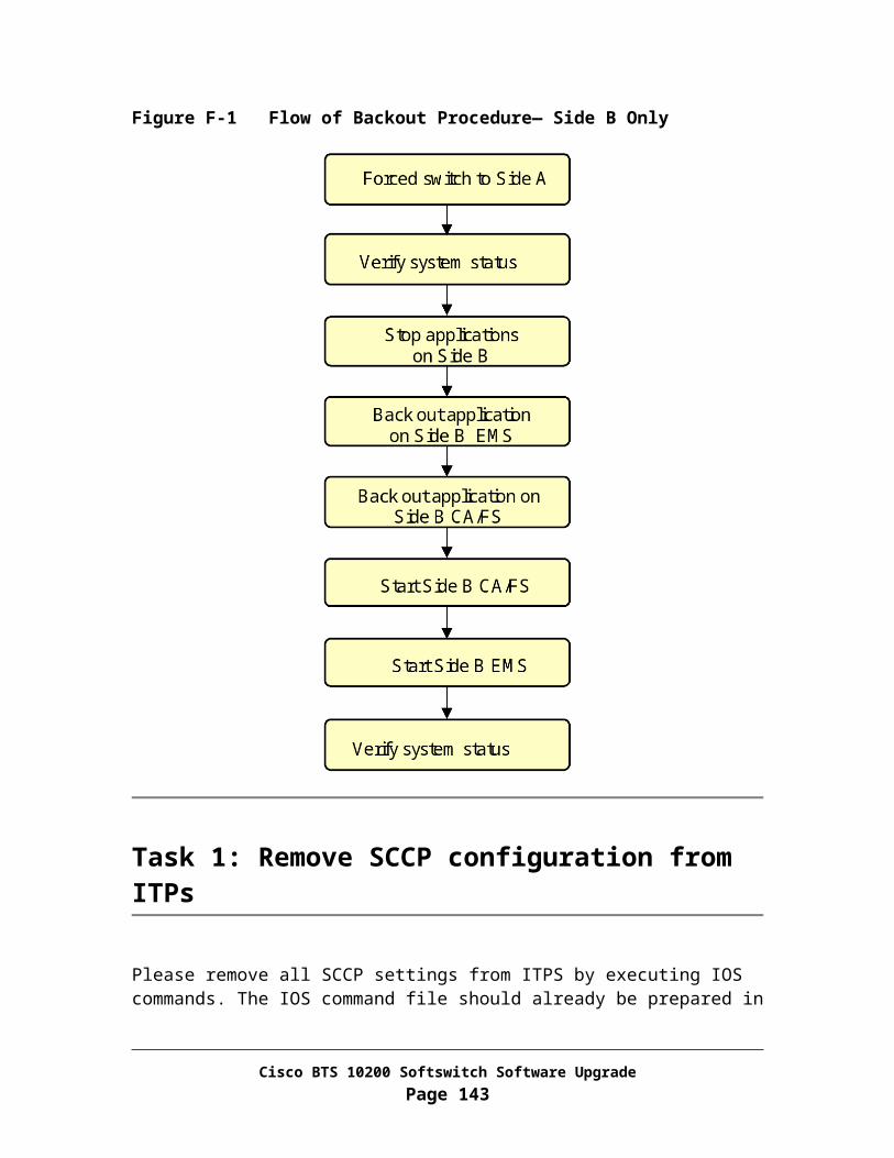
Step 11 CLI>show service fname8=CFU;
Record the service IDs For each service ID found, change existing feature CFU to the new feature
CFVBBG to each service record using the sample CLI command below:
CLI>change service; id=[service id]; FNAME8=CFVBBG;
Step 12 CLI>show service fname9=CFU;
Record the service IDs For each service ID found, change existing feature CFU to the new feature
CFVBBG to each service record using the sample CLI command below:
CLI>change service; id=[service id]; FNAME9=CFVBBG;
Step 13 CLI>show service fname10=CFU;
Record the service IDs For each service ID found, change existing feature CFU to the new feature
CFVBBG to each service record using the sample CLI command below:
CLI>change service; id=[service id]; FNAME10=CFVBBG;
Step 14 CLI>show service fname1=CFUA;
Record the service IDs For each service ID found, change existing feature CFU to the new feature
CFVABBG to each service record using the sample CLI command below:
CLI>change service; id=[service id]; FNAME1=CFVABBG;
Step 15 CLI>show service fname2=CFUA;
Record the service IDs For each service ID found, change existing feature CFU to the new feature
CFVABBG to each service record using the sample CLI command below:
CLI>change service; id=[service id]; FNAME2=CFVABBG;
Step 16 CLI>show service fname3=CFUA;
Record the service IDs For each service ID found, change existing feature CFU to the new feature
CFVABBG to each service record using the sample CLI command below:
Cisco BTS 10200 Softswitch Software UpgradePage 143
CLI>change service; id=[service id]; FNAME3=CFVABBG;
Step 17 CLI>show service fname4=CFUA;
Record the service IDs For each service ID found, change existing feature CFU to the new feature
CFVABBG to each service record using the sample CLI command below:
CLI>change service; id=[service id]; FNAME4=CFVABBG;
Step 18 CLI>show service fname5=CFUA;
Record the service IDs For each service ID found, change existing feature CFU to the new feature
CFVABBG to each service record using the sample CLI command below:
CLI>change service; id=[service id]; FNAME5=CFVABBG;
Step 19 CLI>show service fname6=CFUA;
Record the service IDs For each service ID found, change existing feature CFU to the new feature
CFVABBG to each service record using the sample CLI command below:
CLI>change service; id=[service id]; FNAME6=CFVABBG;
Step 20 CLI>show service fname7=CFUA;
Record the service IDs For each service ID found, change existing feature CFU to the new feature
CFVABBG to each service record using the sample CLI command below:
CLI>change service; id=[service id]; FNAME7=CFVABBG;
Step 21 CLI>show service fname8=CFUA;
Record the service IDs For each service ID found, change existing feature CFU to the new feature
CFVABBG to each service record using the sample CLI command below:
CLI>change service; id=[service id]; FNAME8=CFVABBG;
Step 22 CLI>show service fname9=CFUA;
Record the service IDs
Cisco BTS 10200 Softswitch Software UpgradePage 144

For each service ID found, change existing feature CFU to the new feature CFVABBG to each service record using the sample CLI command below:
CLI>change service; id=[service id]; FNAME9=CFVABBG;
Step 23 CLI>show service fname10=CFUA;
Record the service IDs For each service ID found, change existing feature CFU to the new feature
CFVABBG to each service record using the sample CLI command below:
CLI>change service; id=[service id]; FNAME10=CFVABBG;
Step 24 CLI>show cdp fname=CFUA;
Record all cdp IDs and respective DIGIT_STRING for the cdp record shown For each cdp ID found, change the record using the sample CLI command
below:
CLI>change cdp id=[cdp id]; DIGIT_STRING=[DIGIT_STRING value recorded]; FNAME=CFVABBG
Step 25 CLI>exit
Cisco BTS 10200 Softswitch Software UpgradePage 145
Appendix NSetting up MTP and M3UA Configuration on the Signaling GatewayThis section describes the steps a user must complete to setup the MTP and M3UA configuration on an ITP signaling gateway. This must be completed a week before upgrading from release 3.5.4 to release 4.5.0.
Requirements and Prerequisites
One or two Cisco ITP signaling gateways
Preparation
You must perform the following list of tasks in preparation for setting up the MTP and M3UA configuration:
Obtain the SS7 configuration from the Omni stack. Obtain the IP addresses of the ITP(s). Obtain the point code of the ITP(s). Decide whether to use A-link or D-link configuration. Refer to Appendix V for
details about these configurations. Obtain the IP addresses of the primary and secondary Cisco BTS 10200 call agent
boxes. Physical link connection(s) should be made between the STP and the ITP. A
linkset (and all associated links) should be added to the STP. A route should be added to the STP towards the Cisco BTS 10200 via the ITP. Note that details concerning the method to configure the STP are specific to the STP manufacturer.
Note: 1. All commands to be executed on the ITP are marked in Italics.2. As with all IOS commands, a question mark ‘?’ can be typed at any part of the
command sequence to get a listing of the possible user inputs.3. For details related to the ITP please refer to ITP Configuration Guide
http://www.cisco.com/en/US/products/sw/iosswrel/ps5012/products_feature_guide_book09186a00801752aa.html.
Cisco BTS 10200 Softswitch Software UpgradePage 146

Task 1: Define MTP Variant
In this task, you will define an MTP variant to be used by the ITP.
Step 1 Log in as root to ITP
Step 2 cs7 variant ANSI
The format is as follows: cs7 variant <MTP variant>
Task 2: Define Point Code
In this task, you will define the point code of the ITP. In the A-link setup, ITPs will have the same point code as the Cisco BTS 10200. In the D-link setup, each ITP will have its own point code.
Step 1 cs7 point-code 7.7.7
The format is as follows: cs7 point-code <local point code>
Task 3: Define Ethernet Configuration
Step 1 interface Ethernet0/0 ip address 10.89.232.9 255.255.255.0 ip directed-broadcast no ip mroute-cache full-duplex! interface Ethernet0/1 ip address 10.89.233.41 255.255.255.0 ip directed-broadcast no ip mroute-cache full-duplex!
The format is as follows:>interface Ethernet <interface# / interface#> {see back of ITP for labeling 0/0 or 0/1}>ip address <local ip address> <net mask>
Cisco BTS 10200 Softswitch Software UpgradePage 147

Task 4: Define SGMP (When SG Mated Pair is used)
In this task, you will define the SGMP which provides redundancy for the SG mated pair.
Step 1 cs7 sgmp 9101 local-ip 10.89.232.9
local-ip 10.89.233.41!
The format is as follows:cs7sgmp <Sigtran Adaption Layer> <local port #>local-ip <local ip address 1>local-ip <local ip address 2>
Step 2 cs7 mated-sg ITP2 9101 remote-ip 10.89.232.10
remote-ip 10.89.233.42
The format is as follows:cs7mated-sg <name of mated signaling gateway> <remote port #>remote-ip <remote ip address 1>remote-ip <remote ip address 2>
Task 5: Define M3UA Port Number
In this task, you will define the local port number used by the M3UA layer.
Step 1 cs7 m3ua 2905 local-ip 10.89.232.9
local-ip 10.89.233.41!
The format is as follows:cs7 <Sigtran Adaption Layer> <port #>local-ip <local ip address 1>local-ip <local ip address 2>
Task 6: Define Application Server Process (ASP)
In this task, you will define the ASPs. Two ASPs are defined for each Cisco BTS 10200 call agent, one for the primary and one for secondary.
Step 1 cs7 asp caAspPri 11146 2905 m3ua
Cisco BTS 10200 Softswitch Software UpgradePage 148

remote-ip 10.89.225.209 remote-ip 10.89.226.209!
This command defines the ASP for the primary call agent. The format is as follows:cs7 asp <aspName> <remote IP port> <local IP port> <Sigtran Adaption layer>remote-ip <remote IP address 1>remote-ip <remote IP address 2>
Step 2 cs7 asp caAspSec 11146 2905 m3ua remote-ip 10.89.225.210 remote-ip 10.89.226.210!
This command defines the ASP for the secondary call agent
Task 7: Define SS7 Links
In this task, you will define SS7 links. The syntax of the commands is different for a 2651 and 7505. The equivalent Omni commands are given below.
CRTE-SLK: LSET=LNK0, LSET=LSET0, SLC=0, SPEED=56K, PORT=0, CHANNEL=1;
CRTE-SLK: LSET=LNK1, LSET=LSET1, SLC=0, SPEED=56K, PORT=48, CHANNEL=1;
For 2651:
Step 1 interface Serial0/0:0 no ip address encapsulation mtp2 bandwidth 56 no ip route-cache no ip mroute-cache
The format is as follows:Interface Serial Slot/Portencapsulation <layer 2 protocol>bandwidth <bandwith counted by Kb>{note that all ip related parameters are disabled by adding the ‘no’ prefix.}
Cisco BTS 10200 Softswitch Software UpgradePage 149

Step 2 interface Serial0/1:0 no ip address encapsulation mtp2bandwidth 56 no ip route-cache no ip mroute-cache!
For 7507:
Step 1 interface Serial0/0/0 no ip address encapsulation mtp2bandwidth 56 no ip route-cache no ip mroute-cache
The format is as follows:Interface Serial Slot/Bay/Portencapsulation <layer 2 protocol>{note that all ip related parameters are disabled by adding the ‘no’ prefix.}
Step 2 interface Serial0/0/1 no ip address encapsulation mtp2bandwidth 56 no ip route-cache no ip mroute-cache!
Task 8: Define Linkset
In this task you will define linksets. The equivalent Omni commands are given below.
CRTE-LSET:LSET=LSET0,PC=20-20-20,TYPE=A;
CRTE-LSET:LSET=LSET1,PC=50-50-50,TYPE=A;
20-20-20 and 50-50-50 are the STP point codes.
Step 1 cs7 linkset lset1 20.20.20
Cisco BTS 10200 Softswitch Software UpgradePage 150

link 0 Serial0/0!
Step 2 cs7 linkset lset2 50.50.50 link 0 Serial0/1
The format is as follows:cs7linkset <lset name> <adjacent point code>
link <slc number> <serial interface>
Task 9: Define SS7 Route Sets
In this task you will define SS7 route sets to the DPCs.
Step 1 Configure adjacent routes.
cs7 route-table system update route 20.20.20 255.255.255 linkset lset1 priority 1 update route 50.50.50 255.255.255 linkset lset2 priority 1 update route 20.20.20 255.255.255 linkset lset2 priority 2 update route 50.50.50 255.255.255 linkset lset1 priority 2
The format is as follows:update route <PSTN DPC> <point code mask value> <linkset to APC> <route priority>
These commands define adjacent routes. Note that the direct routes to the adjacent point codes are given a priority of 1 while the indirect routes are given a priority of 2.
The equivalent Omni commands are given below:
CRTE-RSET:RSET=RSET0,PC=20-20-20,RTES=CLSET0;ALW-RSET:RSET=RSET0;CRTE-RSET:RSET=RSET1,PC=50-50-50,RTES=CLSET0;ALW-RSET:RSET=RSET1;
Step 2 Configure routes for DPCs behind the STP (APC)
cs7 route-table system update route 1.1.2 255.255.255 linkset lset1 priority 1 update route 1.1.2 255.255.255 linkset lset2 priority 1 update route 1.1.3 255.255.255 linkset lset1 priority 1 update route 1.1.3 255.255.255 linkset lset2 priority 1 !
Cisco BTS 10200 Softswitch Software UpgradePage 151

The format is as follows:update route <PSTN DPC> <point code mask value> <linkset to APC> <route priority>
These commands defines two routes of equal priority to each DPC with point codes 1.1.2, and 1.1.3 through linksets lset1 and lset2. The equivalent Omni commands are given below.
CRTE-RSET:RSET=RSET2,PC=1-1-2,RTES=CLSET0;ALW-RSET:RSET=RSET2;CRTE-RSET:RSET=RSET3,PC=1-1-3,RTES=CLSET0;ALW-RSET:RSET=RSET3;
Step 3 Check the status of the links to STP (APC) and DPC
show cs7 route
This command displays the status of the links to STPs and DPCs. All links in the system routing table should have the status of “avail”.
Step4 Save the routes
cs7 save route-table flash:routedata.txt
This command saves the routes configured in steps 1 and 2 in the file named routedata.txt. The saved information can be used to configure another ITP.
Task 10: Define Routing Key
In this task, you will create a routing key used by M3UA layer.
Step 1 cs7 as btsAs m3ua routing-key 100 7.7.7
asp caAspPrimary asp caAspSecondary !
The format is as follows:cs7 as <AS Name> <Sigtran Adaption layer>routing-key <routing context value> <Cisco BTS 10200 point code>asp <ASP name for primary Cisco BTS 10200>asp <ASP name for secondary Cisco BTS 10200>
100 is the routing context. This value must match the value defined later (Appendix S, Task 5, Step 1) on in the Cisco BTS 10200 call agent.
Additional routing key values can be added to the routing-key command to further filter the routing from the ITP to the Cisco BTS 10200. For details concerning
Cisco BTS 10200 Softswitch Software UpgradePage 152

adding additional keys please see ITP Configuration Guide http://www.cisco.com/en/US/products/sw/iosswrel/ps5012/products_feature_guide_book09186a00801752aa.html
Cisco BTS 10200 Softswitch Software UpgradePage 153
Appendix OSetting up SCCP configuration on the Signaling GatewayThis section describes the tasks you must perform to setup the SCCP configuration on the ITP signaling gateway. This must be completed a week before upgrading from release 3.5.4 to release 4.5.0.
Note: All commands to be executed on the ITP are marked in Italics.
Task 1: Define SUA Port Number
In this task, you will define the local port number used by the SUA layer.
Step 1 Log in as root to ITP
Step 2 cs7 sua 14001 local-ip 10.89.232.9 local-ip 10.82.233.41!
Task 2: Define ASP
In this task, you will define the ASPs. Two ASPs are defined for each Cisco BTS 10200 AIN and POTS feature servers, one for the primary and one for secondary.
Step 1 cs7 asp fsAinAspPri 12205 14001 m3ua remote-ip 10.89.225.209 remote-ip 10.89.226.209!
This command defines the ASP for the primary AIN feature server 14001 is the local port 12205 is the remote port 10.89.225.209 and 10.89.226.209 are the IP addresses of the primary Cisco BTS
10200
Step 2 cs7 asp fsAinAspSec 12205 14001 m3ua
Cisco BTS 10200 Softswitch Software UpgradePage 154

remote-ip 10.89.225.210 remote-ip 10.89.226.210!
This command defines the ASP for the secondary AIN feature server. 14001 is the local port 12205 is the remote port 10.89.225.210 and 10.89.226.210 are the IP addresses of the secondary Cisco
BTS 10200
Step 3 cs7 asp fsPotsAspPri 12235 14001 m3ua remote-ip 10.89.225.209 remote-ip 10.89.226.209!
This command defines the ASP for the secondary POTS feature server. 14001 is the local port 12235 is the remote port 10.89.225.209 and 10.89.226.209 are the IP addresses of the primary Cisco BTS
10200
Step 4 cs7 asp fsPotsAspSec 12235 14001 m3ua remote-ip 10.89.225.210 remote-ip 10.89.226.210!
This command defines the ASP for the secondary POTS feature server. 14001 is the local port 12235 is the remote port 10.89.225.210 and 10.89.226.210 are the IP addresses of the secondary Cisco
BTS 10200
Task 3: Define Routing Keys for Various Services
In this task, you will define routing keys for CNAM, LNP, IN1 toll free, AIN toll free, and AC and AR services. All the routing context values associated with each routing key must match the routing context values defined later on in the Cisco BTS 10200 AIN and POTS feature servers.
Step 1 cs7 as cnamAs sua routing-key 103 2-42-10 asp fsPtcAspPri
asp fsPtcAspSec !
This command defines the routing key used for CNAM service 103 is the routing context value
Step 2 cs7 as lnpAs sua
Cisco BTS 10200 Softswitch Software UpgradePage 155

routing-key 101 2-42-10 asp fsAinAspPri asp fsAinAspSec !
This command defines the routing key used for LNP service 101 is the routing context value
Step 3 cs7 as in1TfAs sua routing-key 102 2-42-10 asp fsAinAspPri asp fsAinAspSec !
This command defines the routing key used for IN1 toll free service 102 is the routing context value
Step 4 cs7 as in1TfAs sua routing-key 104 2-42-10 asp fsAinAspPri asp fsAinAspSec !
This command defines the routing key used for AIN toll free service 104 is the routing context value
Step 5 cs7 as acarAs sua routing-key 105 2-42-10 asp fsPtcAspPri asp fsPtcAspSec !
This command defines the routing key used for AC and AR services 105 is the routing context value
Task 4: Define GTT Configuration
In this task, you will define the GTT configuration for AC and AR service. The equivalent Omni commands are given below. All the commands have a subsystem number of 251.
CREATE-GT:TT=251,NP=ISDN-TEL,DIG="972",PC=238-14-250,SSN=251,RI=DEF;CREATE-GT:TT=251,NP=ISDN-TEL,DIG="469",PC=238-14-251,SSN=251,RI=DEF;CREATE-GT:TT=251,NP=ISDN-TEL,DIG="214",PC=238-14-252,SSN=251,RI=DEF;CREATE-REMSSN: PC=238-14-250,SSN=251;CREATE-REMSSN: PC=238-14-251,SSN=251;CREATE-REMSSN: PC=238-14-252,SSN=251;
Cisco BTS 10200 Softswitch Software UpgradePage 156
Step 1 conf tcs7 gtt selector acar_sel tt 251gta 972 pcssn 238.14.250 pcssn ssn 251gta 469 pcssn 238.14.251 pcssn ssn 251gta 214 pcssn 238.14.252 pcssn ssn 251!
Step 2 Save the GTT configuration
cs7 save gtt-table flash:gttdata.txt
This command saves the GTT configuration in the file named gttdata.txt. This information can be used to load the GTT configuration during every reload.
Step 3 Load GTT configuration from a file
cs7gtt load gtt-table flash:gttdata.txt
This command loads the GTT configuration from the gttdata.txt file during every reload.
Task 5: Saving the Configuration
In this task, you will save all the ITP configuration changes made so far.
Step 1 wr
Cisco BTS 10200 Softswitch Software UpgradePage 157

Appendix PPreparing for the SS7 UpgradeThis section describes the procedure for preparing for the upgrade. The tasks in this section must be performed right before the starting the upgrade procedure.
Requirements and Prerequisites
Primary and secondary Cisco BTS 10200 EMS and call agent boxes must be up and running with primary being the active and secondary being the standby.
Preparation
You must perform the following list of tasks in preparation for the upgrade: Obtain the point code of the Cisco BTS 10200.
Task 1: Define OPC and NET-AP in SS7-CIC Table
In this task, you will define the OPC and NET-AP values in the SS7-CIC table.
From CA/FS side A
Step 1 Log in as root
Step 2 Find out the OPCs for the system.
1. <hostname># termhandler -node a7n1
2. OMNI [date] #1:display-ospc;
Enter y to continue
Record the OPC
Cisco BTS 10200 Softswitch Software UpgradePage 158

From Active EMS
Step 1 Log in as CLI user
Step 2 CLI> change ss7-cic opc=<OPC for the Cisco BTS 10200 system>; net-ap=0;
Step 3 CLI> show ss7-cic
Verify each record with proper OPC and NET-AP value
Step 4 CLI> exit
Cisco BTS 10200 Softswitch Software UpgradePage 159

Appendix QControlling SS7 Trunk Groups Out of ServiceThis section describes the steps for preparing a script to control all SS7 trunk groups defined in a Cisco BTS 10200 system out of service. The trunk list must be prioritized in an order that the critical ones are controlled out of service last to reduce the SS7 outage time.
This task will accomplish: Identify all the SS7 trunk groups Prepare a CLI provisioning script to control all SS7 trunk groups out of
service
Task 1: Control SS7 Trunk Groups Out of Service
In this task, you will put all SS7 trunk groups out of service (oos).
From Active EMS
Step 1 Log in as CLI user
Step 2 Identify SS7 trunk groups.
CLI> show trunk-grp tg_type=SS7;
Step 3 Following commands must be repeated for all SS7 trunk groups to control each SS7 trunk out of service:
CLI> control trunk-grp id=<Trunk Group ID>; mode=forced; target-state=oos;
Cisco BTS 10200 Softswitch Software UpgradePage 160

Appendix RControlling SS7 Trunk Groups in serviceThis section describes the steps for preparing a script to control all SS7 trunk groups defined in a Cisco BTS 10200 system in service. The trunk list must be prioritized in an order that the critical ones are controlled in service first. This way it will reduce the SS7 outage time.
This task will accomplish: Identify all the SS7 trunk groups Prepare a CLI provisioning script to control all SS7 trunk groups in service
Task 1: Control SS7 Trunk Groups in Service
In this task, you will put all SS7 trunk groups in service (ins).
From Active EMS
Step 1 Log in as CLI user
Step 2 Identify all the SS7 trunk groups.
CLI> show trunk-grp tg_type=SS7;
Step 3 Following commands must be repeated for all SS7 trunk groups to control each SS7 trunk into service:
CLI> control trunk-grp tgn-id=<Trunk Group ID>; mode=forced; target-state=ins;
Cisco BTS 10200 Softswitch Software UpgradePage 161

Appendix SProvisioning Release 4.5.0 Specific Configuration on the Cisco BTS 10200 Call AgentThis chapter describes the procedure for setting up ISUP configuration on the Cisco BTS 10200 call agent.
Requirements and Prerequisites
Secondary Cisco BTS 10200 EMS and call agent boxes must be up and running as active on release 4.5.0.
Primary Cisco BTS 10200 EMS and call agent boxes must be up and running as standby on release 3.5.4.
Preparation
You must perform the following list of tasks in preparation for setting up ISUP configuration:
Obtain the IP addresses of the ITP(s).
Task 1: Define Signaling Gateway Components
In this task, you will define signaling gateway components, which include signaling gateway, signaling gateway process, and signaling gateway group. These components are common to call agent and feature servers and need not be defined multiple times for each platform.
From Active EMS
Step 1 Log in as CLI user
Cisco BTS 10200 Softswitch Software UpgradePage 162
Step 2 Add signaling gateway to the Cisco BTS 10200 system.
CLI> add sg id=sg-1; description=Signaling Gateway 1;
CLI> add sg id=sg-2; description=Signaling Gateway 2;
Step 3 Add signaling gateway process to the Cisco BTS 10200 system.
CLI> add sgp id=sgp-1; sg-id=sg-1; description=Signaling Gateway Process ITP 1;
CLI> add sgp id=sgp-2; sg-id=sg-2; description=Signaling Gateway Process ITP 2;
Step 4 Add signaling gateway group to the Cisco BTS 10200 system.
CLI> add sg-grp id=sg-grp-1; sg1-id=sg-1; sg2-id=sg-2; description=Signaling Gateway Group consisting of both sg-1 and sg-2 for redundancy;
Task 2: Define SCTP Association
In this task, you will define SCTP association profile and SCTP association to each of the signaling gateway processes.
Step 1 CLI> add sctp-assoc-profile id=sctp-prof;
Step 2 CLI> add sctp-assoc id=ca-sctp-assoc1; sgp-id=sgp-1; sctp-assoc-profile-id=sctp-prof; platform-id=CAxxx; remote-tsap-addr1=<ITP 1 First IP Address>; remote-port=2905; dscp=AF11; ip-tos-precedence=ROUTINE; remote-tsap-addr2=<ITP 1 Second IP Address>;
CLI> add sctp-assoc id=ca-sctp-assoc2; sgp-id=sgp-2; sctp-assoc-profile-id=sctp-prof; platform-id=CAxxx; remote-tsap-addr1=<ITP 2 First IP Address>; remote-port=2905; dscp=AF11; ip-tos-precedence=ROUTINE; remote-tsap-addr2=<ITP 2 Second IP Address>;
Remote TSAP addresses 1 and 2 are the ITP’s redundant IP addresses.
Task 3: Define ISUP Variant
Cisco BTS 10200 Softswitch Software UpgradePage 163

In this task, you will define the ISUP variant. In release 3.5.4 only ANSI variant was supported.
Step 1 CLI> add user-part-variant id=ANSISS7_GR317;
Task 4: Define OPC
In this task, you will define the OPC of Cisco BTS 10200. The equivalent Omni command is given below.
CRTE-OSPC:PC=7-7-7, NI=NAT0;
Step 1 CLI> add opc id=opc; point-code=7-7-7;
Point code 7-7-7 is an example.
Task 5: Define Routing Key
In this task, you will define a routing key used by the Cisco BTS 10200 call agent.
Step 1 CLI> add routing-key id=rk1; opc-id=opc; sg-grp-id=sg-grp-1; si=ISUP; rc=100; platform-id=CAxxx;
The routing context defined by the value of the parameter “rc” must be same as the value defined in the ITP (Appendix N, Task 10, Step 1).
Step 2 Bring the SCTP associations in service.
CLI> control sctp-assoc id=ca-sctp-assoc1; target-state=ins; mode=forced;
CLI> control sctp-assoc id=ca-sctp-assoc2; target-state=ins; mode=forced;
Task 6: Define DPC
In this task, you will define DPC. The equivalent Omni commands are given below.
CRTE-RSET:RSET=RSET2, PC=1-1-2, RTES=CLSET0;ALW-RSET:RSET=RSET2;
Cisco BTS 10200 Softswitch Software UpgradePage 164

CRTE-RSET:RSET=RSET3, PC=1-1-3, RTES=CLSET0;ALW-RSET:RSET=RSET3;
Step 1 CLI> add dpc id=dpc1; point-code=1-1-2; description=DPC 1;
CLI> add dpc id=dpc2; point-code=1-1-3; description=DPC 2;
Point code 1-1-2 and 1-1-3 are examples.
Task 7: Define Call Control Routes
In this task, you will define call control routes to the DPCs defined in the previous task.
Step 1 CLI> add call-ctrl-route id=route-dpc1; dpc-id=dpc1; routing-key-id=rk1; si=ISUP; user-part-variant-id=ANSISS7_GR317;
CLI> add call-ctrl-route id=route-dpc2; dpc-id=dpc2; routing-key-id=rk1; si=ISUP; user-part-variant-id=ANSISS7_GR317;
Cisco BTS 10200 Softswitch Software UpgradePage 165
Appendix TProvisioning Release 4.5.0 Specific Configuration on the Cisco BTS 10200 Feature ServerThis chapter describes the procedure for setting up SCCP configuration on the BTS feature server.
Requirements and Prerequisites
Secondary EMS and feature server boxes must be up and running as active on release 4.5.0.
Primary EMS and feature server boxes must be up and running as standby on release 3.5.4.
Task 1: Define SCTP Association
In this task, you will define the one SCTP association to each of the signaling gateway processes for AIN and POTS feature servers. The SCTP association profile is already defined as part of the call agent configuration.
From Active EMS
Step 1 Log in as CLI user
Step 2 CLI> add sctp-assoc id=ain-sctp-assoc1; sgp-id=sgp-1; sctp-assoc-profile-id=sctp-prof; platform-id=FSAINyyy; remote-tsap-addr1=<IP Address>; remote-port=14001; dscp=AF11; ip-tos-precedence=ROUTINE; remote-tsap-addr2=<IP Address>;
CLI> add sctp-assoc id=ain-sctp-assoc2; sgp-id=sgp-2; sctp-assoc-profile-id=sctp-prof; platform-id=FSAINyyy; remote-tsap-addr1=<IP Address>; remote-port=14001; dscp=AF11; ip-tos-precedence=ROUTINE; remote-tsap-addr2=<IP Address>;
These commands add SCTP associations for the AIN feature server.
Cisco BTS 10200 Softswitch Software UpgradePage 166
Step 3 CLI> add sctp-assoc id=pots-sctp-assoc1; sgp-id=sgp-1; sctp-assoc-profile-id=sctp_prof; platform-id=FSPTCzzz; remote-tsap-addr1=<IP Address>; remote-port=14001; dscp=AF11; ip-tos-precedence=ROUTINE; remote-tsap-addr2=<IP Address>;
CLI> add sctp-assoc id=pots-sctp-assoc2; sgp-id=sgp-2; sctp-assoc-profile-id=sctp_prof; platform-id=FSPTCzzz; remote-tsap-addr1=<IP Address>; remote-port=14001; dscp=AF11; ip-tos-precedence=ROUTINE; remote-tsap-addr2=<IP Address>;
These commands add SCTP associations for the POTS feature server.
Step 4 CLI> control sctp-assoc id=ain-sctp-assoc1; target-state=ins; mode=forced;
CLI> control sctp-assoc id=ain-sctp-assoc2; target-state=ins; mode=forced;
CLI> control sctp-assoc id=pots-sctp-assoc1; target-state=ins; mode=forced;
CLI> control sctp-assoc id=pots-sctp-assoc2; target-state=ins; mode=forced;
These commands bring the SCTP associations in service.
Task 2: Add SCCP Network
In this task, you will define a SCCP network.
Step 1 CLI> add sccp-nw id=1; net-ind=NATIONAL; sub-svc=NATIONAL; hop-count=15;
Task 3: Add OPC in POP table
In this task, you will change the old pop table to include the opc-id. If opc-id is not added in the pop table for Rel4.x, the related features (AC, AR, Toll-Free, CNAM, LNP) will not work.
Step 1 CLI> change pop id=1; opc-id=opc;
Task 4: Define CNAM Service
Cisco BTS 10200 Softswitch Software UpgradePage 167

In this task, you will define a CNAM service. The equivalent Omni commands are given below. All of them have a subsystem number of 232.
CREATE-GT:TT=5,NP=ISDN-TEL,DIG="201",PC=238-3-0,SSN=232,RI=DEF;CREATE-GT:TT=5,NP=ISDN-TEL,DIG="202",PC=238-3-0,SSN=232,RI=DEF;CREATE-GT:TT=5,NP=ISDN-TEL,DIG="203",PC=238-3-0,SSN=232,RI=DEF;CREATE-GT:TT=5,NP=ISDN-TEL,DIG="205",PC=238-3-0,SSN=232,RI=DEF;
Step 1 CLI> add dpc id=stp1; point-code=238-3-0; description=STP for CNAM service;
Step 2 CLI> add subsystem-grp id=ss_cnam; tcap-version=ANS92;platform-id=FSPTCzzz; description=CNAM Subsystem;
Step 3 CLI> add subsystem id=ss_cnam; opc_id=opc; local-ssn=232; remote-ssn=232; sccp-nw-id=1; sccp-version=ANS92; application-version=IN1;
Step 4 CLI> add routing-key id=rk_cnam; opc-id=opc; subsystem-grp-id=ss_cnam; sg-grp-id=sg-grp-1; si=SCCP; rc=103; platform-id=FSPTCzzz;
The routing context defined by the value of the parameter “rc” must be same as the value defined in the ITP (Appendix O, Task 3, Step 1).
Step 5 CLI> add sccp-route opc-id=opc; dpc-id=stp1; subsystem-grp-id=ss_cnam; rk-id=rk_cnam;
Step 6 CLI> add slhr-profile id=slhr_cnam; description=Service Logic Host Routing Table for IN1 CNAM service;
Step 7 CLI> add slhr id=slhr_cnam; opc-id=opc; dpc-id=stp1; subsystem-grp-id=ss_cnam; gtt-req=Y; tt=5; gtt_addr_type=CDPN;
Step 8 CLI> add ca-config type=DEFAULT-LIDB-SLHR-ID; datatype=string; value=slhr_cnam;
Step 9 CLI> control subsystem-grp id=ss_cnam; mode=forced; target-state=uis;
This command puts the subsystem in service.
Task 5: Define LNP Service
Cisco BTS 10200 Softswitch Software UpgradePage 168

In this task, you will define a LNP service. The equivalent Omni commands are given below. All of them have a subsystem number of 247.
CREATE-GT:TT=11,NP=ISDN-TEL,DIG="334",PC=238-153-0,SSN=247,RI=DEF;CREATE-GT:TT=11,NP=ISDN-TEL,DIG="678",PC=238-153-0,SSN=247,RI=DEF;CREATE-GT:TT=11,NP=ISDN-TEL,DIG="404",PC=238-153-0,SSN=247,RI=DEF;CREATE-GT:TT=11,NP=ISDN-TEL,DIG="706",PC=238-153-0,SSN=247,RI=DEF;CREATE-GT:TT=11,NP=ISDN-TEL,DIG="770",PC=238-153-0,SSN=247,RI=DEF;
Step 1 CLI> add dpc id=stp2; point-code=238-153-0; description=STP for LNP service;
Step 2 CLI> add subsystem-grp id=ss_lnp; tcap-version=ANS92; platform-id=FSAINyyy; description=LNP Subsystem;
Step 3 CLI> add subsystem id=ss_lnp; opc_id=opc; local-ssn=247; remote-ssn=247; sccp-nw-id=1; sccp-version=ANS92; application-version=AIN01;
Step 4 CLI> add routing-key id=rk_lnp; opc-id=opc; subsystem-grp-id=ss_lnp; sg-grp-id=sg-grp; si=SCCP; rc=101; platform-id=FSAINyyy;
The routing context defined by the value of the parameter “rc” must be same as the value defined in the ITP (Appendix O, Task 3, Step 2).
Step 5 CLI> add sccp-route opc-id=opc; dpc-id=stp2; subsystem-grp-id=ss_lnp; rk-id=rk_lnp;
Step 6 CLI> add slhr-profile id=slhr_lnp; description=Service Logic Host Routing Table for AIN LNP service;
Step 7 CLI> add slhr id=slhr_lnp; opc-id=opc; dpc-id=stp2; subsystem-grp-id=ss_lnp; gtt-req=Y; tt=11;
Step 8 CLI> add ca-config type=DEFAULT-LNP-SLHR-ID; datatype=string; value=slhr_lnp;
Step 9 CLI> control subsystem-grp id=ss_lnp; mode=forced; target-state=uis;
This command puts the subsystem in service.
Task 6: Define IN1 Toll Free Service
Cisco BTS 10200 Softswitch Software UpgradePage 169
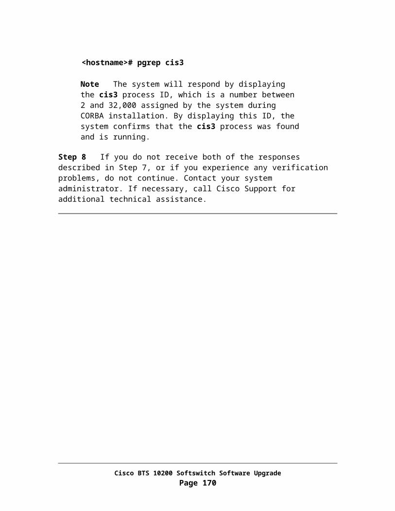
In this task, you will define IN1 toll free service. The equivalent Omni commands are given below. All of them have a subsystem number of 254.
CREATE-GT:TT=254,NP=ISDN-TEL,DIG="800",PC=238-14-254,SSN=254,RI=DEF;CREATE-GT:TT=254,NP=ISDN-TEL,DIG="866",PC=238-14-254,SSN=254,RI=DEF;CREATE-GT:TT=254,NP=ISDN-TEL,DIG="888",PC=238-14-254,SSN=254,RI=DEF;CREATE-GT:TT=254,NP=ISDN-TEL,DIG="877",PC=238-14-254,SSN=254,RI=DEF;
Step 1 CLI> add dpc id=stp3; point-code=238-14-254; description=STP for Toll Free service;
Step 2 CLI> add subsystem-grp id=ss_tf; tcap-version=ANS92; platform-id=FSAINyyy; description=Toll Free Subsystem;
Step 3 CLI> add subsystem id=ss_tf; opc_id=opc; local-ssn=254; remote-ssn=254; sccp-nw-id=1; sccp-version=ANS92; application-version=IN1;
Step 4 CLI> add routing-key id=rk_tf; opc-id=opc; subsystem-grp-id=ss_tf; sg-grp-id=sg-grp; si=SCCP; rc=102; platform-id=FSAINyyy;
The routing context defined by the value of the parameter “rc” must be same as the value defined in the ITP (Appendix O, Task 3, Step 3).
Step 5 CLI> add sccp-route opc-id=opc; dpc-id=stp3; subsystem-grp-id=ss_tf; rk-id=rk_tf;
Step 6 CLI> add slhr-profile id=slhr_tf; description=Service Logic Host Routing Table for IN1 Toll Free service;
Step 7 CLI> add slhr id=slhr_tf; opc-id=opc; dpc-id=stp3; subsystem-grp-id=ss_tf; gtt-req=Y; tt=254;
Step 8 CLI> add ca-config type=DEFAULT-TOLL-FREE-SLHR-ID; datatype=string; value=slhr_tf;
Step 9 CLI> control subsystem-grp id=ss_tf; mode=forced; target-state=uis;
This command puts the subsystem in service.
Task 7: Define AIN Toll Free Service
Cisco BTS 10200 Softswitch Software UpgradePage 170
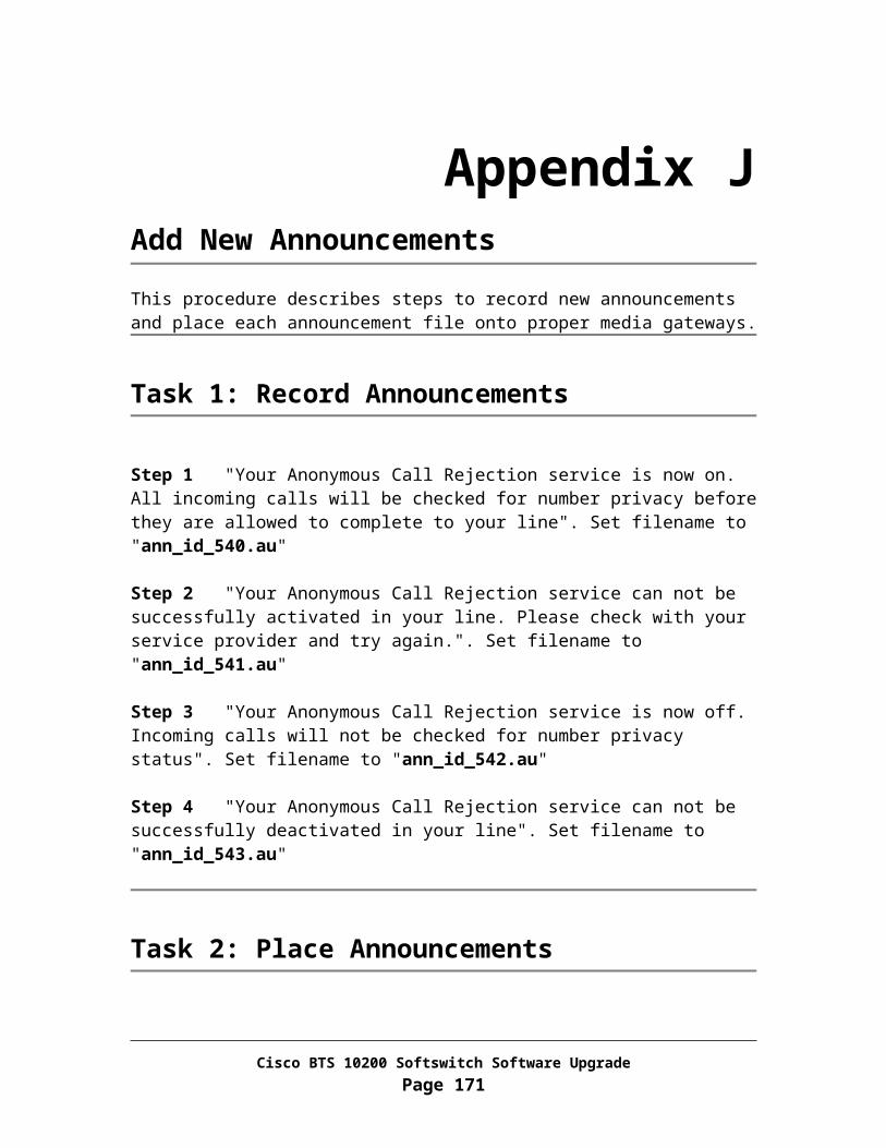
In this task, you will define an AIN toll free service. The equivalent Omni commands are given below. All of them have a subsystem number of 248.
CREATE-GT:TT=8,NP=ISDN-TEL,DIG="800",PC=238-14-253,SSN=248,RI=DEF;CREATE-GT:TT=8,NP=ISDN-TEL,DIG="866",PC=238-14-253,SSN=248,RI=DEF;CREATE-GT:TT=8,NP=ISDN-TEL,DIG="888",PC=238-14-253,SSN=248,RI=DEF;CREATE-GT:TT=8,NP=ISDN-TEL,DIG="877",PC=238-14-253,SSN=248,RI=DEF;
Step 1 CLI> add dpc id=stp4; point-code=238-14-253; description=STP for Toll Free service;
Step 2 CLI> add subsystem-grp id=ss_aintf; tcap-version=ANS92; platform-id=FSAINyyy; description=Toll Free Subsystem;
Step 3 CLI> add subsystem id=ss_aintf; opc_id=opc; local-ssn=248; remote-ssn=248; sccp-nw-id=1; sccp-version=ANS92; application-version=IN1;
Step 4 CLI> add routing-key id=rk_aintf; opc-id=opc; subsystem-grp-id=ss_ aintf; sg-grp-id=sg-grp; si=SCCP; rc=104; platform-id=FSAINyyy;
The routing context defined by the value of the parameter “rc” must be same as the value defined in the ITP (Appendix O, Task 3, Step 4).
Step 5 CLI> add sccp-route opc-id=opc; dpc-id=stp4; subsystem-grp-id=ss_aintf; rk-id=rk_aintf;
Step 6 CLI> add slhr-profile id=slhr_aintf; description=Service Logic Host Routing Table for IN1 Toll Free service;
Step 7 CLI> add slhr id=slhr_aintf; opc-id=opc; dpc-id=stp4; subsystem-grp-id=ss_aintf; gtt-req=Y; tt=8;
Step 8 CLI> add ca-config type=DEFAULT-TOLL-FREE-SLHR-ID; datatype=string; value=slhr_aintf;
Step 9 CLI> control subsystem-grp id=ss_aintf; mode=forced; target-state=uis;
This command puts the subsystem in service.
Task 8: Define AC and AR Services
Cisco BTS 10200 Softswitch Software UpgradePage 171

In this task, you will define AC and AR services. The equivalent Omni commands are defined below. All of them have a subsystem number of 251.
CREATE-GT:TT=251,NP=ISDN-TEL,DIG="972",PC=238-14-250,SSN=251,RI=DEF;CREATE-GT:TT=251,NP=ISDN-TEL,DIG="469",PC=238-14-251,SSN=251,RI=DEF;CREATE-GT:TT=251,NP=ISDN-TEL,DIG="214",PC=238-14-252,SSN=251,RI=DEF;……CREATE-GT:TT=251,NP=ISDN-TEL,DIG="919",PC=238-10-201,SSN=251,RI=DEF;……CREATE-REMSSN: PC=238-14-250,SSN=251;CREATE-REMSSN: PC=238-14-251,SSN=251;CREATE-REMSSN: PC=238-14-252,SSN=251;……CREATE-REMSSN: PC=238-10-201,SSN=251;……CREATE-GT:TT=251,NP=ISDN-TEL,DIG="512",PC=2-42-10,SSN=251,RI=DEF;
Step 1 CLI> add dpc id=itp1; point-code=7-7-7; description=ITP for AC and AR services;
Step 2 CLI> add subsystem-grp id=ss_acar; tcap-version=ANS92; platform-id=FSPTCzzz; description=AC AR Subsystem;
Step 3 CLI> add subsystem id=ss_acar; opc_id=opc; local-ssn=251; remote-ssn=251; sccp-nw-id=1; sccp-version=ANS92; application-version=IN1;
Step 4 CLI> add routing-key id=rk_acar; opc-id=opc; subsystem-grp-id=ss_acar; sg-grp-id=sg-grp; si=SCCP; rc=105; platform-id=FSPTCzzz;
The routing context defined by the value of the parameter “rc” must be same as the value defined in the ITP (Appendix O, Task 3, Step 5).
Step 5 CLI> add sccp-route opc-id=opc; dpc-id=itp1; subsystem-grp-id=ss_acar; rk-id=rk_acar;
Step 6 CLI> add slhr-profile id=slhr_acar; description=Service Logic Host Routing Table for IN1 Toll Free service;
Step 7 CLI> add slhr id=slhr_acar; opc-id=opc; dpc-id=itp1; subsystem-grp-id=ss_acar; gtt-req=Y; tt=251;
Step 8 CLI> add ca-config type=ACAR -SLHR-ID; datatype=string; value=slhr_acar;
Step 9 CLI> add dpc id=sw_mask1; point-code=238-14-0; description=ITP for AC and AR services;
Cisco BTS 10200 Softswitch Software UpgradePage 172

Step 10 CLI> add dpc id=sw1; point-code=238-10-201; description=ITP for AC and AR services;
Step 11 CLI> add sccp-route opc-id=opc; dpc-id=sw_mask; subsystem-grp-id=ss_acar; rk-id=rk_acar;
Step 12 CLI> add sccp-route opc-id=opc; dpc-id=sw1; subsystem-grp-id=ss_acar; rk-id=rk_acar;
Step 13 CLI> control subsystem-grp id=ss_acar; mode=forced; target-state=uis;
This command puts the subsystem in service.
Cisco BTS 10200 Softswitch Software UpgradePage 173

Appendix UTesting the SS7 UpgradeThis chapter describes the procedure for testing to check if the SS7 part of the upgrade from release 3.5.4 to release 4.5.0 was successful.
Requirements and Prerequisites
Secondary EMS and feature server boxes must be up and running as active on release 4.5.0.
Primary EMS and feature server boxes must be up and running as standby on release 3.5.4.
Release 4.5.0 specific configuration should be provisioned on the Cisco BTS 10200 call agent and feature servers.
Task 1: Check the Status of SCTP Associations
In this task, you will check the status of SCTP associations.
From Active EMS
Step 1 Log in as CLI user
Step 2 CLI> status sctp-assoc id=ca-sctp-assoc1; CLI> status sctp-assoc id=ca-sctp-assoc2; CLI> status sctp-assoc id=ain-sctp-assoc1; CLI> status sctp-assoc id=ain-sctp-assoc2; CLI> status sctp-assoc id=pots-sctp-assoc1; CLI> status sctp-assoc id=pots-sctp-assoc2;
The admin state of all SCTP associations should be ADMIN_INS and operational state should be “SCTP-ASSOC in service”.
Cisco BTS 10200 Softswitch Software UpgradePage 174

Task 2: Check the Status of the Signaling Gateway Processes
In this task, you will check the status of signaling gateway processes.
Step 1 CLI> status sgp id=sgp-1; CLI> status sgp id=sgp-2;
The operational state returned by the call agent and feature server platforms should be “SGP in service”.
Task 3: Check the Status of DPCs
In this task, you will check the status of DPCs associated with the call agent and AIN feature server.
Step 1 CLI> status dpc id=dpc1; platform-id=CAxxx; CLI> status dpc id=dpc2; platform-id=CAxxx; CLI> status dpc id=stp1; platform-id=FSAINyyy; CLI> status dpc id=stp2; platform-id=FSAINyyy; CLI> status dpc id=stp3; platform-id=FSAINyyy; CLI> status dpc id=stp4; platform-id=FSAINyyy; CLI> status dpc id=itp1; platform-id=FSAINyyy;
The operational state of all the DPCs should be “DPC available”.
Task 4: Check the Status of Trunk Terminations
In this task, you will check the status of all the SS7 trunk terminations.
Step 1 CLI> status tt tgn-id=1; cic=all;
All trunks should have an admin state of ADMIN_INS (3rd column) and operation state of NON_FAULTY (7th column).
This command should be repeated for all SS7 trunk groups.
Task 5: Check the Status of Subsystems
In this task, you will check the status of various subsystems.
Cisco BTS 10200 Softswitch Software UpgradePage 175

Step 1 CLI> status subsystem id=ss_cnam; opc-id=opc; CLI> status subsystem id=ss_lnp; opc-id=opc; CLI> status subsystem id=ss_tf; opc-id=opc; CLI> status subsystem id=ss_aintf; opc-id=opc; CLI> status subsystem id=ss_acar; opc-id=opc;
The operational state of all subsystems should be “Subsystem allowed”.
Task 6: Make a SS7 Call
In this task, you will make a subscriber to SS7 call to verify the SS7 upgrade.
Step 1 From a subscriber line, dial a number, which is handled by one of the DPCs and verify if the call completes successfully.
Cisco BTS 10200 Softswitch Software UpgradePage 176

Appendix VD-Link Configuration
The following diagram illustrates a ‘D’ link configuration when an ITP is utilized
Figure 1: Cisco BTS 10200 release 4.5.0 D link configuration
The D link configuration has advantages and disadvantages compared to the A link configuration. The advantages are:
The Signaling Gateways can be geographically separated (even after distributed MTP3 is implemented, the ‘A’ link configuration will not allow two SGPs to be geographically separated - in separate cities for example).
Multiple small (2651) SGs can currently be utilized for hardware redundancy.
The disadvantage of the ‘D’ link configuration is that each SG has to have its own point code.
Cisco BTS 10200 Softswitch Software UpgradePage 177
DPC1
DPC2D link
D link
SG1 (STP1)
SG2 (STP2)
SG-Group
PC 5.5.5
STPSTP
STPSTPPC 4.4.4
BTS10200
PC 7.7.7
SSP
Location A
Location B
20.20.20
50.50.50
1.1.2
1.1.3

Cisco BTS 10200 Softswitch Software UpgradePage 178

Appendix WPreparing Disks for Upgrade
This software upgrade will need 8 disks: 2 for each machine. Each set of 2 disks must have the same model number in order for disk mirroring to work.
The NIDS information required for disk preparation must be different from that used on the system to be upgraded.
Task 1: Locate and label the disks
Label disks for EMS Side A
Locate two new disk drives identical to the machine to be upgraded and label the first disk drive as “Release 4.5.0 EMS side A disk0, 1” and the second disk drive as “Release 4.5.0 EMS side A disk0, 2”. Please follow the steps below to prepare the two disk drives. The second disk drive will be used as the backup in case the first disk drive goes bad.
Label disks for EMS Side B
Locate two new disk drives identical to the machine to be upgraded and label the first disk drive as “Release 4.5.0 EMS side B disk0, 1” and the second disk drive as “Release 4.5.0 EMS side B disk0, 2”. Please follow the steps below to prepare the two disk drives. The second disk drive will be used as the backup in case the first disk drive goes bad.
Label disks for CA/FS Side A
Locate two new disk drives identical to the machine to be upgraded and label the first disk drive as “Release 4.5.0 CA/FS side A disk0, 1” and the second disk drive as
Cisco BTS 10200 Softswitch Software UpgradePage 179

“Release 4.5.0 CA/FS side A disk0, 2”. Please follow the steps below to prepare the two disk drives. The second disk drive will be used as the backup in case the first disk drive goes bad.
Label disks for CA/FS Side B
Locate two new disk drives identical to the machine to be upgraded and label the first disk drive as “Release 4.5.0 CA/FS side B disk0, 1” and the second disk drive as “Release 4.5.0 CA/FS side B disk0, 2”. Please follow the steps below to prepare the two disk drives. The second disk drive will be used as the backup in case the first disk drive goes bad.
Task 2: Disk slot lay out
Netra 240 disk slot lay out:
Disk 0 Disk 1
DVD-ROM SunFire V240 disk slot lay out:
Disk 2 Disk 3
Disk 0 Disk 1 DVD-ROM SunFire V440 disk slot lay out:
Disk 3 DVD-ROM
Disk 2
Disk 1
Disk 0 Netra 1280 disk slot lay out:
DVD-ROM
Cisco BTS 10200 Softswitch Software UpgradePage 180

Disk 1
Disk 0 Netra 20 disk slot lay out:
DISK
0
DISK
1
DVDROM
Continuous Hardware disk slot lay out:
CD-ROM Disk 0 Disk 2
Disk 1 Disk 3
Task 3: Construct opticall.cfg
Step 1 Get a copy of Cisco BTS 10200 Software Release 4.5.0 Network Information Data Sheets (NIDS)
Step 2 Fill in NIDS information for the BTS system used for disk preparation. The NIDS information must be different from that used on the system to be upgraded.
Step 3 Get a copy of Cisco BTS 10200 Software Release 4.5.0 opticall.cfg
Step 4 Fill in parameters in opticall.cfg from NIDS and placed it on a server which will be accessible from the BTS system used for disk preparation.
Task 4: Disk preparation
Repeat the steps in Task 4 to prepare the second disk.
Note: Please perform disk preparation for each machine in parallel.
Cisco BTS 10200 Softswitch Software UpgradePage 181
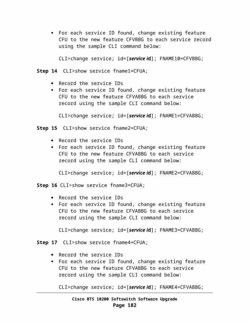
For both EMS side A and B
Step 1 Locate a system with the identical hardware as the machine to be upgraded
Step 2 Put disk to disk slot 0
Step 3 Jumpstart the machine with Solaris 10 OS
Step 4 Configured the machine with 4/2 network configuration
Step 5 Stage Cisco BTS 10200 Software Release 4.5.0 to the /opt/Build directory.
Step 6 ftp opticall.cfg from the server (where the file was placed in Task 3) and place it under /etc directory.
<hostname># /opt/Build/checkCFG
o To verify the information entered are free of errors.
Note: The EMS side A and side B installation must be started in parallel.
Step 7 Install Cisco BTS 10200 Software Release 4.5.0 application software.
<hostname># /opt/Build/install.sh
o Answer “y” when prompt. This installation process could take up to 1hour and 30 minutes.
o Answer "y” when prompt for “reboot”
o Wait for the system to boot up. Then Log in as root
Step 8 <hostname># mv /etc/rc3.d/S99platform /etc/rc3.d/_S99platform
Step 9 Remove all network interface configuration information from the machine:
<hostname># \rm /etc/hostname.*
Step 10 Shutdown the system
Cisco BTS 10200 Softswitch Software UpgradePage 182
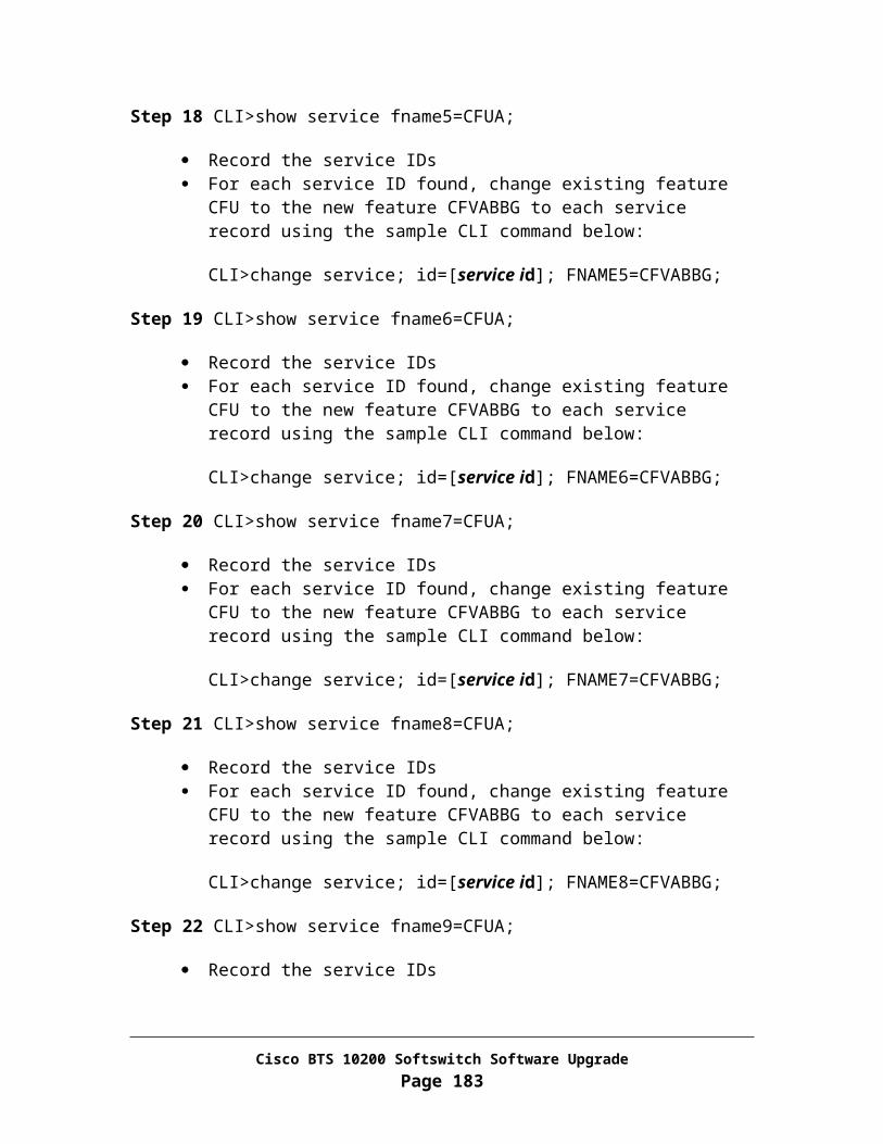
<hostname># platform stop all<hostname># sync;sync<hostname># shutdown –i5 –g0 -y
Step 11 Power off the machine and remove the disks to be used for upgrade.
For both CA/FS side A and B
Step 1 Locate a system with the identical hardware as the machine to be upgraded
Step 2 Put disk to disk slot 0
Step 3 Jumpstart the machine with Solaris 10 OS
Step 4 Configured the machine with 4/2 network configuration
Step 5 Stage Cisco BTS 10200 Software Release 4.5.0 to the /opt/Build directory.
Step 6 ftp opticall.cfg from the server (where the file was placed in Task 3) and place it under /etc directory.
Step 7 Install BTSbase, BTSinst, BTSossh and BTShard packages:
<hostname># cd /opt/Build <hostname># pkgadd –d . BTSbase Answer “y” when prompt <hostname># pkgadd –d . BTSinst Answer “y” when prompt <hostname># pkgadd –d . BTSossh Answer “y” when prompt <hostname># pkgadd –d . BTShard Answer “y” when prompt <hostname># cd /etc/rc3.d <hostname># mv S99platform _S99platform <hostname># shutdown –i6 –g0 -y Wait for system to boot up and login as root.
Step 8 Remove all network interface configuration information from the machine:
<hostname># \rm /etc/hostname.*
Step 9 Update version information:
Cisco BTS 10200 Softswitch Software UpgradePage 183

<hostname># cd /opt/ems/utils
<hostname># echo “900-04.04.00.V00” > Version
Step 10 Shutdown the system
<hostname># shutdown –i5 –g0 -y
Step 11 Power off the machine and remove the disks to be used for upgrade.
Cisco BTS 10200 Softswitch Software UpgradePage 184

Appendix XDisk Mirroring after Upgrade
It takes about two to two and half hours to complete the disk mirroring process on each machine. Please schedule the task accordingly. Cisco recommends a separate maintenance window to complete the upgrade process.
The disk mirroring process assumes the Applications on Primary side A are in Active state and Secondary Side B are in standby state.
Task 1: Configuring the Secondary EMS Side B
Step 1 Login as root.
Step 2 <hostname># /opt/setup/setup_mirror_ems
Step 3 <hostname># reboot -- -r
Step 4 Wait for the system to boot, then log in to EMS Side B as root.
Step 5 <hostname># /opt/setup/sync_mirror
Note Wait for the disks to synchronize before continuing. The synchronization can be verified by running the Resync_status command from the /opt/utils directory. The display will show the resyncing in progress and reports resync completion.
Step 6 Exit EMS Side B
Task 2: Configuring the Secondary CA/FS Side B
Step 1 Login as root.
Step 2 <hostname># /opt/setup/setup_mirror_ca
Cisco BTS 10200 Softswitch Software UpgradePage 185

Step 3 <hostname># reboot -- -r
Step 4 Wait for the system to boot, then log in to CA/FS Side B as root.
Step 5 <hostname># /opt/setup/sync_mirror
Note Wait for the disks to synchronize before continuing. The synchronization can be verified by running the Resync_status command from the /opt/utils directory. The display will show the resyncing in progress and reports resync completion.
Step 6 Exit CA/FS Side B
Task 3: Switchover Applications to the Secondary Side
From Active EMS Side A
Step 1 Log in as CLI user
Step 2 CLI> control call-agent id=CAxxx; target-state=standby-active;
Step 3 CLI> control feature-server id=FSPTCyyy; target-state=standby-active;
Step 4 CLI> control feature-server id=FSAINzzz; target-state=standby-active;
Step 5 CLI> control bdms id=BDMS01; target-state=standby-active;
Step 6 CLI> control element-manager id=EM01; target-state=standby-active;
Step 7 CLI> exit
Task 4: Configuring the Primary EMS Side A
Step 1 Login as root.
Step 2 <hostname># /opt/setup/setup_mirror_ems
Step 3 <hostname># reboot -- -r
Cisco BTS 10200 Softswitch Software UpgradePage 186

Step 4 Wait for the system to boot, then log in to EMS Side A as root.
Step 5 <hostname># /opt/setup/sync_mirror
Note Wait for the disks to synchronize before continuing. The synchronization can be verified by running the Resync_status command from the /opt/utils directory. The display will show the resyncing in progress and reports resync completion.
Step 6 Exit EMS Side A
Task 5: Configuring the Primary CA/FS Side A
Step 1 Login as root.
Step 2 <hostname># /opt/setup/setup_mirror_ca
Step 3 <hostname># reboot -- -r
Step 4 Wait for the system to boot, then log in to CA/FS Side A as root.
Step 5 <hostname># /opt/setup/sync_mirror
Note Wait for the disks to synchronize before continuing. The synchronization can be verified by running the Resync_status command from the /opt/utils directory. The display will show the resyncing in progress and reports resync completion.
Step 6 Exit CA/FS Side A
Task 6: Restore the System to Normal Mode
From Active EMS Side A
Step 1 Log in as CLI user
Cisco BTS 10200 Softswitch Software UpgradePage 187

Step 2 CLI> control call-agent id=CAxxx; target-state=active-standby;
Step 3 CLI> control feature-server id=FSPTCyyy; target-state=active-standby;
Step 4 CLI> control feature-server id=FSAINzzz; target-state=active-standby;
Step 5 CLI> control bdms id=BDMS01; target-state=active-standby;
Step 6 CLI> control element-manager id=EM01; target-state=active-standby;
Step 7 CLI> exit
This completes the disk mirroring process
Cisco BTS 10200 Softswitch Software UpgradePage 188

Appendix YBounce SS7 TrunksThis section describes the steps for preparing a script to bounce SS7 trunks. The trunk list must be prioritized in an order that the critical ones are controlled out of service last and controlled in service first. This way it will reduce the SS7 outage time.
This task will accomplish: Identify all the SS7 trunks Prepare a CLI provisioning script to bounce SS7 trunks
Task 1: Bounce SS7 Trunks
You’ll identify SS7 trunks, control each trunk out of service, unequip, equip, in service.
From Active EMS
Step 1 Log in as CLI user
Step 2 Identify all the SS7 trunk groups.
CLI> show trunk-grp tg_type=SS7;
Step 3 Following commands must be repeated for all SS7 trunk groups:
CLI> control trunk-termination tgn-id=<Trunk Group ID>; cic=all; mode=forced; target-state=oos;
CLI> unequip trunk-termination tgn-id=<Trunk Group ID>; cic=all;
CLI> equip trunk-termination tgn-id=<Trunk Group ID>; cic=all;
CLI> control trunk-termination tgn-id=<Trunk Group ID>; cic=all; mode=forced; target-state=ins;
Cisco BTS 10200 Softswitch Software UpgradePage 189