chapter 1 introduction to charge pump …shodhganga.inflibnet.ac.in/bitstream/10603/24464/6/06...4...
TRANSCRIPT

1
CHAPTER 1
INTRODUCTION TO CHARGE PUMP BASED PLL
1.1 INTRODUCTION
Phase Locked Loop (PLL) is a simple feedback system (Dan
Wolaver, 1991) that compares the output phase with the input phase and
produces the output frequency which is proportional to the input phase
difference. It is widely used in wireless frequency synthesis, clock data
recovery and clock generation. In all the PLL applications, it is required to
generate low noise and low spur signals, while achieving fast settling time.
In a PLL, the phase difference between the reference signal (often
from a crystal oscillator) and the output signal is translated into two signals
known as UP signal from pMOS and DOWN (DN) signal from nMOS often
called as control signals. These two control signals are used to steer current
into or out of a capacitor causing the voltage across the capacitor to increase
or decrease. In each cycle, the time during which the switch is turned ON is
proportional to the phase difference. Hence, the charge delivered is dependent
on the phase difference also. The voltage on the capacitor is used to tune a
Voltage Controlled Oscillator (VCO), generating the desired output signal
frequency. The use of a Charge Pump (CP) naturally adds a pole at the origin
in the loop transfer function of the PLL, since the CP current (ICP) is driven
into a capacitor to generate a voltage V, (V=ICP/(sC)). The additional pole at
the origin is desirable, when considering the closed-loop transfer function of
the PLL. This pole (S) at the origin integrates the error signal and causes the

2
system to track the input with one more order. The CP in a PLL design is
constructed in an Integrated-Circuit (IC) technology, consisting of pull-up,
pull-down transistors and on-chip capacitors. A resistor is also added to
stabilize the closed-loop PLL. The detailed study of simple PLL architecture
is discussed in section 1.12.
1.2 BASIC CHARGE PUMP PLL
The Charge Pump PLL (CPPLL) is an extension of the basic PLL
which requires the addition of a CP between the phase detector and loop-filter.
The CP converts the voltage fluctuation in the Phase detector to
corresponding current signal thereby reduces the static error. Figure 1.1
shows the usage of CP between Phase Detector and Loop Filter (LF).
Figure 1.1 Charge Pump Based PLL
The CP shown in Figure 1.2 consists of a set of current sources
with magnitudes of IP1 and IP2 amps respectively. In most cases, the current
sources are symmetrical. Thus IP1 = IP2 = IP.

3
Figure 1.2 Charge Pump
In the above circuit, one source (IP) is connected to the positive
supply rail while the other (-IP ) is connected to the negative supply rail. The
sources are separated by two switches S1 and S2. The output of the phase
detector provides the gating signals U (UP) and D (DN) which turn
on S1 and S2 respectively. The Phase Detector is designed such that, the
switches are never ON simultaneously. When U is high and D is low
then, S1 is ON and S2 is OFF. This causes current to flow out of the pump and
into the loop-filter. When U is low and D is high then Q1 is OFF and Q2 is ON
which causes current to flow out of loop-filter and into the pump.
A representative Complementary Metal Oxide Semiconductor
(CMOS) CP circuit is shown in Figure 1.3. The VPBIAS and VNBIAS voltages
set the positive and negative CP currents respectively. An equal UP/DN
current over entire control voltage range reduces the static phase error. Care
should be taken that the minimal coupling to the control voltage during
switching and leakage. It is very insensitive to power-supply noise and
process variations and the loop stability.

4
Figure 1.3 Charge pump biasing
1.3 THEORY OF CHARGE PUMP PLL
The theory of basic CPPLL is discussed here. Figure 1.4 shows the
construction of CPPLL
Figure 1.4 Simple CPPLL
The reference input is applied to the one of the PFD and VCO
output is given to another input. This implementation senses the transition at
5
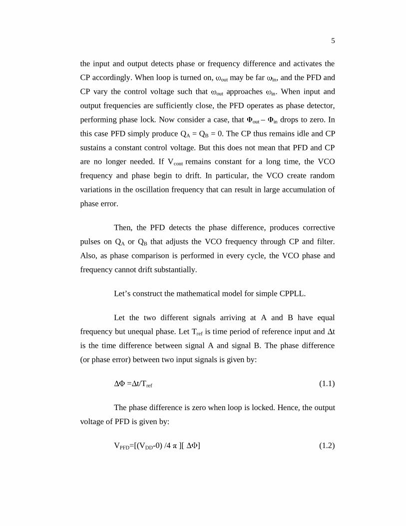
the input and output detects phase or frequency difference and activates the
CP accordingly. When loop is turned on, out may be far in, and the PFD and
CP vary the control voltage such that out approaches in. When input and
output frequencies are sufficiently close, the PFD operates as phase detector,
performing phase lock. Now consider a case, that out – in drops to zero. In
this case PFD simply produce QA = QB = 0. The CP thus remains idle and CP
sustains a constant control voltage. But this does not mean that PFD and CP
are no longer needed. If Vcont remains constant for a long time, the VCO
frequency and phase begin to drift. In particular, the VCO create random
variations in the oscillation frequency that can result in large accumulation of
phase error.
Then, the PFD detects the phase difference, produces corrective
pulses on QA or QB that adjusts the VCO frequency through CP and filter.
Also, as phase comparison is performed in every cycle, the VCO phase and
frequency cannot drift substantially.
Let’s construct the mathematical model for simple CPPLL.
Let the two different signals arriving at A and B have equal
frequency but unequal phase. Let Tref is time period of reference input and t
is the time difference between signal A and signal B. The phase difference
(or phase error) between two input signals is given by:
= t/Tref (1.1)
The phase difference is zero when loop is locked. Hence, the output
voltage of PFD is given by:
VPFD=[(VDD-0) /4 ][ ] (1.2)

6
Hence, the gain of PFD is given by:
KPFD= VDD /4 [volts/rad] (1.3)
The output of the PFD is then given to the CP, then the
characteristic of IP (CP current, Up or Down) is of Signum function is Ip=Ip=
sgn( ) That is, Ip is +Ip if is positive and Ip is -Ip if this phase error is
negative. Now in locked condition of PLL, the ON time of UP or DOWN
switch is given by:
tp = [ /2 fin] s (1.4)
Then the current delivered to the filter Cp for the time tp on each
cycle is given by:
Id=[Ip-(Ip)/ 4 ][ ] (1.5)
KPFD= IP/2 (1.6)
Thus the control voltage generated across the CP is given by:
Vc(s) =Id (s)/ Zc(s) =[IP/2 ] [Zc(s)] ]=PPFD CK (1.7)
PPFD CK =IP/2 Cp[Volts/rad] (1.8)
in a locked condition, suddenly = o u(t) phase difference is introduced.
QA will produce the pulses which are t = T/2 sec, which leads to output
to rise by (IP/CP) (T/2 ) ) in every period. Approximating this to a
ramp voltage we can write:

7
Vc(t)=[IP/2 Cp][ t u(t)] (1.9)
This leads to impulse response:
Hence, the transfer function of PFD-CP-Filter combination is given
by:
h(t)= [IP/2 Cp] u(t)] (1.10)
Vcont/ (S)=(IP/2 Cp) (1/S) (1.11)
This output of PFD-CP-Filter combination is then given to the
VCO with transfer function as (KVCO/S). Then the open loop transfer function
of simple CPPLL as:
out/ in) (S)|open =(IP/2 Cp) (KVCO/S2) (1.12)
Since the open loop gain has two poles at origin, this topology is
called as “type II” PLL. The closed loop transfer function is given by:
P VCO
P
2 P VCO
P
I K2 CH(S) I Ks
2 C
(1.13)
This result is alarming, because closed loop system contains two
imaginary poles and therefore unstable. In order to stabilize the system, a zero
is added in the loop gain by adding a resistor Rp in series with the loop filter
capacitor.

8
The PFD-CP-Filter now has the transfer function:
cont PP
P
V I 1(s) R2 C s
(1.14)
Thus, the closed loop transfer function of this system becomes:
P VCOp p
P
2 P PVCO p VCO
p
I K R C s 12 CH(S) I IS K R s K
2 2 C
(1.15)
The closed loop system contains a zero at sz = -1/(RpCp). The
natural frequency and the damping ratio are given as:
P VCOn
p
I K2 C
(1.16)
p P p VCOR I C K2 2
(1.17)
As expected, if Rp=0, then =0. With complex poles, the decay
time constant is given by1/( n) = 4 /(RpIPKVCO).
As seen from the Equation (1.15), if the value of IP KVCO decreases,
the gain crossover frequency decreases (or shifts toward the origin),
degrading the phase margin.
1.4 NON IDEAL EFFECTS IN CHARGE PUMP
1. As shown in Figure 1.4, switches are constructed using PMOS
and NMOS. The inherent mismatches between these two
switches result in mismatch in charging and discharging

9
current in addition to timing mismatch. Though there is a
variation in control voltage at the output and the W/L ratios
are adjusted so as to have equal UP and DOWN currents.
Even though about 0.6% of mismatching is observed between
these currents in simulation, means that the two current
sources are mismatched and the control voltage experiences the random changes in it.
2. There is also a Charge Sharing problem at the output node of
CP (in fact between filter capacitor) and the parasitic
capacitances between Drain and Source of switch transistors.
This causes a sudden change in control voltage which may disturb the VCO.
3. Another effect found in CP is Clock Feed Through. The high
frequency signal provided at the gate of switch transistor
passes to the output node via gate to drain parasitic capacitor
Cgd. This also results in jumps in control voltage. Since the
VCO sensitivity is high, even a small jump in control voltage
results a large jump in output frequency.
4. One more effect is limited output voltage swing. If the higher
output voltage is needed the current source value must be
increased. This is not possible in every condition, because it
increases power consumption.
Apart from these, a reference spur in PLL is also one of the major problems which arise due to current mismatches in CP.
By considering all the non ideal effects, many researchers are trying
to remove it from CP by using various architectures which is discussed in
Chapter 2 in detail.

10
1.5 LIMITATION AND SCOPE FOR IMPROVEMENT
PLL plays an indispensable place in the electronics and wireless/
Radio Frequency (RF) based communication network design. There is always
a huge demand for a PLL design with high lock range, low current mismatch
in the CP, PLL with high stability and gain. The idea of error amplifier based
CP design is proposed Xuan Xiangguang et al (2008), which claims that there
is scope for improvement in the following aspects
To increase the stability and reduce the jitter problem in the
higher order frequency.
To explore the methods for reducing the current mismatch in
the CP due to transistor Channel Length Modulation (CLM)
and the process variation.
To derive a circuit which could provide high output voltage,
high driving capability, high power efficiency, and/or small
silicon area occupation.
To find a method to arrest the process and temperature
variation in the PLL.
1.6 STATE OF ART
After making a thorough study of the literature mentioned in
Chapter 2, it is found that, many researchers have been done for developing a
CPPLL which could withstand the process and temperature compensation.
Some researchers have concentrated on the VCO design for gain
compensation and increasing the stability of the PLL. Few works have been
reported for the development of gain boosting structure and current matching
characteristics. The previous works have reported a mismatch reduction of

11
0.6%. Gobbi et al (2006) tried to develop a four phase Dickson CP where the
output impedance is independent of output current. Even if the Charge
Sharing problem could be reduced but still there is a big challenge for the
mismatch reduction in the CP design.
Some researchers have concentrated on the development of Low
noise based VCO, to have higher PLL locking range in their design.
1.7 MOTIVATION BEHIND THIS RESEARCH
PLL is the heart of the many modern electronics as well as
communication system. Recently plenty of the researches have conducted on
the design of PLL circuit and still research is going on this topic. Most of the
researches have conducted to realize a higher lock range PLL with lesser lock
time and have tolerable phase noise. The most versatile application of the
PLL is for clock generation and clock recovery in microprocessor, networking,
communication systems, and frequency synthesizers. Phase Locked-Loops
(PLLs) are commonly used to generate well-timed on-chip clocks in
high-performance digital systems. Modern wireless communication systems
employ PLL mainly for synchronization, clock synthesis, skew and jitter
reduction. It finds wide application in various advanced communication and
instrumentation systems.
Recent advances in integrated circuit design techniques have led to
the development of high performance PLL which has become more
economical and reliable. Now a whole PLL circuit can be integrated as a part
of a larger circuit on a single chip. There are mainly five blocks in a PLL.
These are Phase Frequency Detector (PFD), CP, Loop Filter (LF), Voltage
Controlled Oscillator (VCO) and Frequency Divider (FD). Presently almost
all communication and electronics devices operate at a higher frequency; a
12
faster locking PLL is needed. Hence there are lot of challenges in designing a
CP with reduced mismatch in the CP current and thereby providing an
appropriate control voltage for the VCO and thereby it tracks the incoming
frequency.
This work mainly concentrates on the development of low
mismatch in the CP current and increases the lock range of the PLL.
This research focuses on the design and development of CP based
PLL with the objective of boosting the gain, reducing the current mismatch
of the CP, increasing the output impedance, reducing the CLM effect and
Charge Sharing problem. It also aimed for reduction of glitches at higher
frequency.
1.8 OBJECTIVE OF THIS RESEARCH
The main objectives of this research is
To achieve less than 1% difference of the Up/Down current
and to reduce the process variation like pressure, temperatures
and operating voltage variations which could be achieved
during manufacturing.
To increase the output resistance without adding more cascode
devices.
To design a circuit to avoid the CLM effect and Charge
sharing problem.
To design a circuit in order to minimize the high speed
glitches.

13
1.9 METHODOLOGY FOLLOWED
The methodology followed for this research work is as follows:
The complete design including the transmission gate and inclusion
of charge removal have been made in the Cadence Design Environment and
the simulation (both dc and ac) is done using Spectre and the model file used
from the foundry TSMC with 180nm technology file. The locking range of
the design is verified by setting up a hardware environment with PLL design
network, Cathode Ray Oscilloscope (CRO) and Function Generator (FG).
Since the Spectre supports the foundry file simulation, it is being used for all
our design work. The complete design methodology and the techniques
applied for our design is shown in the Figure 5.3.
The design of CP based PLL with the objective of improving the
output impedance and hence the gain, reducing the current mismatch of the
CP, reducing the CLM effect and charge sharing problem.
The technique is to be applied for the sake of reducing the current
mismatch by the use of cascode and self biasing. The output impedance of the
design is to be improved by the concept of cascade structure and the CLM can
be reduced by the technique of increasing the length of the transistor.
The technique of Charge Sharing is applied by using the charge
removal transistor. Transmission gates are applied for the removal of glitches
in this design. The detailed discussion of different techniques are used for the
development of CPPLL is shown in Figure 1.5.

14
Figure 1.5 Approach Flow Diagram of the Proposed Research Work
15
1.10 TOOLS AND TECHNOLOGY FILE USED
The architecture design is being done in the Transistor level and it
involves the manual calculation and the Tool which supports Transistor level
design. The Cadence Virtuoso 5.1 is used for the transistor level design and
its simulation design is done using Spectre Tool. The working procedure with
Cadence ADE has been attached in the Appendix 1 and the data sheet of
TL082 is attached in the Appendix 2. the TL082 is a general purpose Junction
Field Effect Transistor (JFET) operational amplifier (opamp), which is
consider to be an error amplifier for this work in order to get good current
matching characteristics. There are few tools which support the design
simulation like HSpice, Spectre and PSpice. It is preferred to use Spectre for
simulation for its accuracy and technology support. Also a foundry support is
from Taiwan Semiconductor Manufacturing Corporation (TSMC) (i.e)
technology model files 180nm from TSMC for simulation. Since this is
foundry dependent, it is also preferred to use this for simulation and in case
backend layout design is required we could take this work and the tool could
be taken for finishing the design.
1.11 EXPECTED OUTCOMES OF THIS RESEARCH
This research is expected to provide the following advantages over
the existing PLL system design. The expected outcomes of this research are:
To reduce the current matching characteristics in the CPPLL
which is less than 0.6 % by using an opamp with reference
current source.
To obtain high output impedance of the CP with the help of
cascode structure and hence high gain is to be achieved,

16
Low voltage cascode current mirror and charge removal
transistors are being used to eliminate CLM effect and Charge
Sharing problem respectively.
The high speed glitches are to be eliminated with the help of
matched transmission gates.
1.12 OVERVIEW OF PLL
Since its invention in1932, the basic PLL has remained nearly the
same but its implementation in different technologies and for different
applications continues to challenge designers. This topic deals with basics of
PLL. Figure 1.6 shows the block diagram of PLL.
Figure 1.6 Basic Block Diagram of PLL
A phase detector is a circuit whose average output voltage is
proportional to the phase difference , between two inputs. In an ideal case,
the relation between the average output voltage and the input phase difference
being linear, it crosses the origin for =0 as shown in Figure 1.7.

17
Figure 1.7 Phase Detector Characteristics
Called the gain of PD is the slope of line, KPD, which is expressed
in V/rad.
The output of PD is then passed through a low pass filter, so as to
remove the high frequency content in PD output voltage. This is required
because the control voltage of oscillator must remain quiet in steady state.
Filter also provides a memory for the loop in case lock is momentarily lost
due to large interference transient.
This filtered control voltage is then applied to the input of Voltage
Controlled Oscillator. Control voltage forces the VCO to change the
frequency in the direction that reduces the difference between input frequency
and output frequency. If two frequencies are sufficiently close, the PLL
feedback mechanism forces the two PD input frequency frequencies to be
equal and the VCO is locked with incoming frequency. This is called as
locked state of PLL.

18
Figure 1.8 depicts the basic operation of PLL.
Figure 1.8 Basic Operation of PLL
Once the loop is in locked state, there will be small phase
difference between the two PD input phase signals. This phase difference
results in a dc voltage at the phase detector output which is required to shift
the VCO from its free running frequency to input frequency and keeps the
loop in locked state.
1.12.1 Dynamics of Simple PLL
A linear model of PLL can be constructed mathematically by
considering Figure 1.9 which shows the linear model of type I PLL. Low pass
filter is assumed to be of first order for simplicity.

19
Figure 1.9 Linear Model of Type I PLL
The PD output contains a dc component equal to KPD ( out - in) as
well as high frequency components which are filtered by the LPF. PD is
simply modeled as a subtractor whose output is amplified by KPD. The overall
PLL model consists of the phase subtractor, the LPF transfer function 1/(1+
s/ LPF) , where LPF is the 3 dB bandwidth and the VCO transfer function
KVCO/S. Here, in and out are the excess phases of input and output
waveforms, respectively.
The open loop transfer function is given by
outopen open
in
VCOPD
LPF
H(s) | (S) |
K1K s s1
(1.18)
where, KPD is the gain of Phase detector, KVCO is the gain of VCO and LPF is
the 3 dB bandwidth of Low Pass Filter.

20
From Equation (1.18) closed loop transfer function can be obtained
as:
PD VCOclosed 2
PD VCOLPF
K KH(s) |s s K K
(1.19)
Here H(s)|closed is simply denoted by out/ in. Further, since the
frequency and phase are related by a linear operator, the transfer function of
Equation (1.19) can be expressed as:
out PD VCO2
inPD VCO
LPF
K K(S)s s K K
(1.20)
This is second order transfer function of type I PLL. Using the
control theory approach the “natural frequency” and “damping ratio” are
given by:
n LPF PD VCOK K (1.21)
LPF
PD VCO
12 K K
(1.22)
The step response is given by:
nt 2out n2
1(t) 1 e sin 1 t u(t)1
(1.23)
where out denotes the change in output frequency and 1 2sin 1 .
Thus, as per control theory approach, the step response will contain a

21
sinusoidal component with frequency 2n 1 that will decay with time
constant ( n)-1.
Referring to above discussion it can be concluded that:
1. Settling speed of PLL is of great concern in most applications.
Equation (1.23) thus, shows that the exponential decay
determines how fast the output approaches its final value,
provided that n is maximized. Equations (1.21) and (1.22),
yield,
n LPF12
(1.24)
This result shows the critical tradeoff between settling speed and
ripple on the VCO control line. If the cutoff frequency of filter is reduce the,
greater high frequency components are suppressed but at the same time pull in
time increases.
2. In addition to the product of n and the value of is also
important. If is less than typically 0.5, step response exhibits
high amplitude oscillations before settling. Hence in order to
avoid this ringing, the value of damping ratio is normally kept
0.707 or even greater than or equal to 1.
3. Equation (1.22) shows that both phase error and are
inversely proportional to KPD and KVCO. Hence lowering the
phase error makes the system less stable. Thus in summary the
simple PLL (type I) has a drawback of trade off between the
pull in time, the ripple on the control voltage, the phase error
and the stability.

22
1.12.2 Types of PLL
Several types of PLL (Floyd Gardner 1999) architectures are
available in market. The architectures broadly range according to the
application. These different architectures of PLL can be considered as
different types of PLL. Following types of PLL are classified according to
their application.
1. Programmable PLL: This type of PLL can be programmed
for wide range of signals.
2. Single and multi-phase PLL: These can control a single or
many phases. They are used in digital clock networks.
3. Digital Phase Locked Loop: They are used digital input
signals for application like Manchester coding.
4. PLL with lock detector: It uses a lock on one of the pins and
is used in frequency modulation.
5. PLL frequency synthesizer: These are used to synthesize the
frequency of different range and band.
6. PLL FM/AM demodulator: The FM/AM radio frequencies
are modulated and demodulated using this type of PLL.
7. Single RF/ Multi RF PLL: It is used for controlling single or
multiple radio frequencies.
8. Super PLL: It is used for frequency synthesizing of radios,
networks of GSM, cordless phones, etc.
PLLs are also classified according to the type of loop filter used in
architecture. The order of loop filter is the type of PLL. For example, if first

23
order loop filter is used, then it is called as type I PLL. If second order filter is
used, it is called as type II PLL and so on.
If PLL uses simple “Phase detector” in its architecture, it is called
as simple PLL. But if PLL uses “Phase Frequency Detector” accompanied
with “CP”, it is called as “CPPLL”.
1.13 NON IDEAL EFFECTS IN PLL
So many imperfections always remain in practical PLL circuit.
These lead to high ripple on the control voltage even when the loop is locked.
These ripples modulate the VCO frequency, which results in non periodic
waveform. This section considers these non ideal effects in PLL (Dan
Wolaver 1991, Jakob Baker et al 2003, Behzad Razavi 2002).
1.13.1 Jitter in PLL
A jitter is the short term-term variations of a signal with respect to
its ideal position in time. This problem negatively impacts the data
transmission quality. Deviation from the ideal position can occur on either
leading edge or trailing edge of signal. Jitter may be induced and coupled onto
a clock signal from several different sources and is not uniform over all
frequencies. Excessive jitter can increase Bit Error Rate (BER) of
communication signal. In digital system Jitter leads to violation in time
margins, causing circuits to behave improperly. Common sources of jitter
include:
Internal circuitry of PLL
Random Thermal noise from crystal
Other resonation devices
Random mechanical noise from crystal vibration

24
Signal transmitters
Traces and cables
Connectors
Receivers
The response of PLL to jitter is very important in most applications.
Figure 1.10 explains the jitter in PLL.
As shown in Figure 1.10, a strictly periodic waveform, x1(t),
contains zero crossings that are evenly spaced in time. Now consider nearly
periodic signal x2(t), whose period experiences a small changes, deviating the
zero crossing from their ideal points. Hence we can say that x2(t) suffers from
jitter. If the instantaneous frequency of signal varies slowly from one period
to next period, then it is called as “slow jitter”, and if the variation is fast, it is
called as fast jitter.
Figure 1.10 Ideal and Jittery Waveforms
25
In PLL two types of phenomena are considered. a) The input
exhibits jitter and b) The VCO produces jitter.
In first case, the transfer function derived for type I and type II
PLLs have a low-pass characteristics, indicating that if in(t) varies rapidly,
then out(t) does not fully track the variations. That means, slow jitter at the
input propagates to the output unattenuated but fast jitter does not. That is,
PLL low pass filters in(t).
If PLL is modelled for transfer function of out VCO for type II, the
transfer function depicts the high pass characteristics. That is, slow jitter
components generated by VCO are suppressed but fast jitter components are
not. If VCO changes slowly, then the comparison with perfectly periodic
input waveform generates slowly varying error that propagates through LPF
and adjusts the VCO frequency, thereby counteracting the change in VCO.
On other hand if VCO varies rapidly, then error produced by the phase
detector is heavily attenuated by the poles in loop, failing to correct the
change.
1.13.2 Phase Noise
Phase noise is random variation of phase of the signal. It is the
frequency domain representation of rapid, short term fluctuations in the phase
of the wave, caused by time domain instabilities (“jitter”). Generally the
phase noise and jitter are closely related. Or more specifically, radio engineer
call it as phase noise, but digital system engineer call it as jitter of the clock.
Phase noise is of very much concern in PLL, since it directly affects the entire
performance of the system. Following are the common sources of phase noise
in PLL.

26
i) Oscillator noise: There are two oscillators that contribute to
the phase noise of the PLL. One is the reference oscillator and
other is the VCO. Although both oscillators can be modelled
similarly, their effects on the output noise are distinct just due
to their position in the loop. If a noise less VCO is added with
AWGN with DSPSD of No/2, then the output power spectrum
is given by KVCO2(No/2 2). Though it is very simplified
equation, it clearly gives the idea of output noise of PLL in the
presence of VCO noise. The reference oscillator is also
assumed to have sufficient behavior with different constant of
proportionality.
ii) Frequency Divider noise: The excess noise of a digital
divider can be modelled as additive noise source at its output.
In a PLL, this noise directly appears at the input of phase
detector and experiences the same transfer function as the
noise on the input terminal.
iii) Phase detector noise: Usually phase detectors are not major
sources of noise in PLLs. As the work of PD is to detect the
phase difference, any random variation in the phase of input
signal makes the phase detector to produce wrong output,
which is get transferred through filter and tunes the VCO
wrongly.
1.13.3 Reference Spur
Reference spurs are spurious emissions that occur from the carrier
frequency at an offset equal to the channel spacing. These are usually caused
by leakage and mismatch in CP of PLL. Though they occur outside the band

27
of interest, they can enter the mixers and be translated back onto band of
interest.
Reference spur mainly occurs in CPPLL. Though there is no phase
difference between reference and feedback signal, in the locked state, the
phase detector (or phase frequency detector) produces very narrow pulse
width error voltage which drives the CP. Although these pulses have a very
narrow width, the fact that they exist means that the dc voltage driving the
VCO is modulated by a signal of frequency equal to input reference frequency.
This produces reference spurs in the RF output occurring at offset frequencies
that are integer multiples of input reference frequency. A spectrum analyzer
can be used to detect reference spurs. Simply increasing the span to greater
than twice the reference frequency reduces the spur.
Let Icp is CP current, Ileak is leakage current in CP then the phase
offset is given by:
leak
cp
I2 radI
(1.25)
Now if fREF is the input reference frequency, fBW is loop bandwidth,
fpl is the frequency of pole in loop filter and N is the division value then the
amount of reference spur in 3rd order PLL is given by:
dBcfflog20N
ff
21log20P
PL
REF
REF
BWr (1.26)
If reference spur is not enough to meet the requirement, the loop
bandwidth should be further narrowed or CP current should be increased. It is
also helpful to reduce the division value to relax the CP design.

28
1.14 APPLICATIONS OF PLL
Since its invention, PLL continues to find new applications in
electronics, communication and instrumentation. Examples include memories,
microprocessors, hard disk drive electronics, RF and wireless transceivers,
clock recovery circuits on microcontroller boards and optical fibre receivers.
Some of the applications are as follows (Dan Wolaver 2003).
1.14.1 Frequency Multiplication and Synthesis
A PLL can be modified such that it multiplies its input frequency
by factor of M. Figure 1.11 shows the basic frequency multiplication concept.
Figure 1.11 Frequency Multiplication
Just like a voltage divider is used in feedback in voltage amplifier,
as shown in Figure 1.11, output frequency of PLL is divided by M and
applied to the phase detector, we get, fout=M fin. Also, since fin and fD must be
equal, PLL multiplies fin by M.
Some systems require a periodic waveform whose frequency (a)
must be very accurate and (b) can be varied in very fine stapes. Hence,to
synthesize a required frequency, a channel control word (digital) is applied to

29
divider block in feedback that varies the value of M. Since fout= M fREF, the
relative accuracy of fout is equal to that of fREF. It is also notable that fout varies
in stapes equal to fREF if M changes by one each time.
1.14.2 Skew Reduction
This is one of the very popular and earliest uses of PLL. Suppose
synchronous pair of data and clock lines enter a large digital chip. Since clock
typically drives a large number of transistors and logic interconnects, it is first
applied to large buffer. Thus, the clock distributed on chip may suffer from
substantial skew (delay due to buffer insertion) with respect to data. This is an
undesirable effect which reduces the timing budget for on-chip operations.
Now consider the circuit as shown in Figure 1.12. Here input clock
CKin is applied to on chip PLL and buffer is placed inside the loop. Since PLL
guarantees a nominally zero phase difference between CKin and CKB, the
skew is eliminated. That is, the constant phase shift introduced by the buffer
is divided by infinite loop gain of the feedback system. Alignment of VVCO
with CKin is not important since VVCO is not used.
Figure 1.12 Use of PLL to Eliminate Skew

30
1.15 ORGANISATION OF THE THESIS
The thesis is organized as follows:
Chapter 1 gave a brief introduction about the PLL and CP based
PLL design and its application in the domain of wireless communication
network and clock synthesis network. It also discusses the motivation behind
this research, previous work on this topic and their result analysis,
shortcoming in the previous work and the scope for improvement. The
methodology followed for the research, Tools and model file usage from the
foundry and the expected outcome of this research has been discussed. The
conventional PLL design and its components have been discussed.
Chapter 2 discusses the previous works done in the area of design
a PLL with more stability, gain, low power design, increasing the lock range
and its analysis. The interpretations made by different researchers have been
analyzed and the way it helps our understanding of our research and
improvement has been dealt in detail.
Chapter 3 deals with the design of gain boosting CP, which could
increase the output impedance with the help of cascode structure. A
mathematical derivation which could justify the mismatch reduction and
improving Rout has been discussed in detail with appropriate illustration.
Discussion is also made, to get high stability and its simulation using spectre
tool has also been shown. The Locking of the reference signal with the
incoming signal for the conventional and proposed design is shown in this
chapter.
Chapter 4 deals with the design of high performance CP which
could reduce the current mismatch in the CP from 0.6% in existence to 0.08%.

31
It also deals with the appropriate selection of aspect ratio in the design of CP
based PLL which could reduce the CLM and Charge Sharing problem.
The recorded values of the mismatch between the UP and DOWN
signal from the CP and their simulation results have been shown. It also
shows the drawback of jitter existence in this design.
Chapter 5 deals with technique proposed for the removal of jitter
while operating with higher frequency range. A detailed discussion has been
made for the modified CP design and its simulated output has also been
shown.
Chapter 6 discussed about the analysis, interpretation of the
simulated results and the results obtained from the hardware setup. Also, the
future scope for the improvement of this research work has been discussed in
detail.