chapter 1b1morris/cpe100/fa17/slides/ddca_ch1_cpe100_morris_v1.pdfchapter 1 background • digital...
TRANSCRIPT

Chapter 1 <1>
Professor Brendan Morris, SEB 3216, [email protected] http://www.ee.unlv.edu/~b1morris/cpe100/
Chapter 1
CPE100: Digital Logic Design I
Section 1004: Dr. Morris
From Zero to One
Chapter 1 <2>
Background: Digital Logic Design
• How have digital devices changed the world?
• How have digital devices changed your life?

Chapter 1 <3>
Background
• Digital Devices have revolutionized our world • Internet, cell phones, rapid advances in medicine, etc.
• The semiconductor industry has grown from $21 billion in 1985 to over $300 billion in 2015
Chapter 1 <4>
The Game Plan
• Purpose of course:
• Learn the principles of digital design
• Learn to systematically debug increasingly complex designs

Chapter 1 <5>
Chapter 1: Topics
• The Art of Managing Complexity
• The Digital Abstraction
• Number Systems
• Addition
• Binary Codes
• Signed Numbers
• Logic Gates
• Logic Levels
• CMOS Transistors
• Power Consumption
Chapter 1 <6>
The Art of Managing Complexity
• Abstraction
• Discipline
• The Three –y’s
• Hierarchy
• Modularity
• Regularity

Chapter 1 <7>
Abstraction
• What is abstraction?
• Hiding details when they are not important
• Electronic computer abstraction
• Different levels with different building blocks
focu
s o
f th
is c
ou
rse
programs
device drivers
instructions
registers
datapaths
controllers
adders
memories
AND gates
NOT gates
amplifiers
filters
transistors
diodes
electrons

Chapter 1 <8>
Discipline
• Intentionally restrict design choices
• Example: Digital discipline
– Discrete voltages (0 V, 5 V) instead of continuous
(0V – 5V)
– Simpler to design than analog circuits – can build
more sophisticated systems
– Digital systems replacing analog predecessors:
• i.e., digital cameras, digital television, cell phones,
CDs

Chapter 1 <9>
The Three –y’s
• Hierarchy
• A system divided into modules and submodules
• Modularity
• Having well-defined functions and interfaces
• Regularity
• Encouraging uniformity, so modules can be easily
reused

Chapter 1 <10>
Example: Flintlock Rifle
• Hierarchy
• Three main modules: Lock, stock, and barrel
• Submodules of lock: Hammer, flint, frizzen, etc.

Chapter 1 <11>
Example Flintlock Rifle
• Modularity
• Function of stock: mount barrel and lock
• Interface of stock: length and location of mounting pins
• Regularity
• Interchangeable parts

Chapter 1 <12>
The Art of Managing Complexity
• Abstraction
• Discipline
• The Three –y’s
• Hierarchy
• Modularity
• Regularity

Chapter 1 <13>
The Digital Abstraction
• Most physical variables are continuous
• Voltage on a wire (1.33 V, 9 V, 12.2 V)
• Frequency of an oscillation (60 Hz, 33.3 Hz, 44.1 kHz)
• Position of mass (0.25 m, 3.2 m)
• Digital abstraction considers discrete subset of values
• 0 V, 5 V
• “0”, “1”

Chapter 1 <14>
The Analytical Engine
• Designed by Charles Babbage from 1834 – 1871
• Considered to be the first digital computer
• Built from mechanical gears, where each gear represented a discrete value (0-9)
• Babbage died before it was finished

Chapter 1 <15>
Digital Discipline: Binary Values
• Two discrete values
• 1 and 0
• 1 = TRUE = HIGH = ON
• 0 = FALSE = LOW = OFF
• How to represent 1 and 0
• Voltage levels, rotating gears, fluid levels, etc.
• Digital circuits use voltage levels to represent 1 and 0
• Bit = binary digit
• Represents the status of a digital signal (2 values)

Chapter 1 <16>
Why Digital Systems?
• Easier to design
• Fast
• Can overcome noise
• Error detection/correction

Chapter 1 <17>
George Boole, 1815-1864
• Born to working class parents
• Taught himself mathematics and joined the faculty of Queen’s College in Ireland
• Wrote An Investigation of the Laws of Thought (1854)
• Introduced binary variables
• Introduced the three fundamental logic operations: AND, OR, and NOT

Chapter 1 <18>
Number Systems
• Decimal
• Base 10
• Binary
• Base 2
• Hexadecimal
• Base 16
Chapter 1 <19>
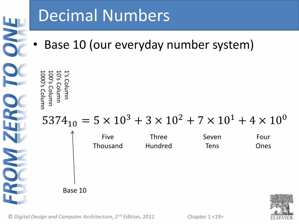
Decimal Numbers
• Base 10 (our everyday number system)
537410 = 5 × 10³ + 3 × 10² + 7 × 101 + 4 × 100
1’s C
olu
mn
1
0’s C
olu
mn
1
00
’s Co
lum
n
10
00
’s Co
lum
n
Five Thousand
Three Hundred
Seven Tens
Four Ones
Base 10

Chapter 1 <20>
Binary Numbers
• Base 2 (computer number system)
11012 = 1 × 23 + 1 × 22 + 0 × 21 + 1 × 20
1’s C
olu
mn
2
’s Co
lum
n
4’s C
olu
mn
8
’s Co
lum
n
One Eight
One Four
Zero Two
One One
Base 2

Chapter 1 <21>
Powers of Two
• 20 =
• 21 =
• 22 =
• 23 =
• 24 =
• 25 =
• 26 =
• 27 =
• 28 =
• 29 =
• 210 =
• 211 =
• 212 =
• 213 =
• 214 =
• 215 =

Chapter 1 <22>
Powers of Two
• 20 = 1
• 21 = 2
• 22 = 4
• 23 = 8
• 24 = 16
• 25 = 32
• 26 = 64
• 27 = 128
• Handy to memorize up to 210
• 28 = 256
• 29 = 512
• 210 = 1024
• 211 = 2048
• 212 = 4096
• 213 = 8192
• 214 = 16384
• 215 = 32768
Chapter 1 <23>
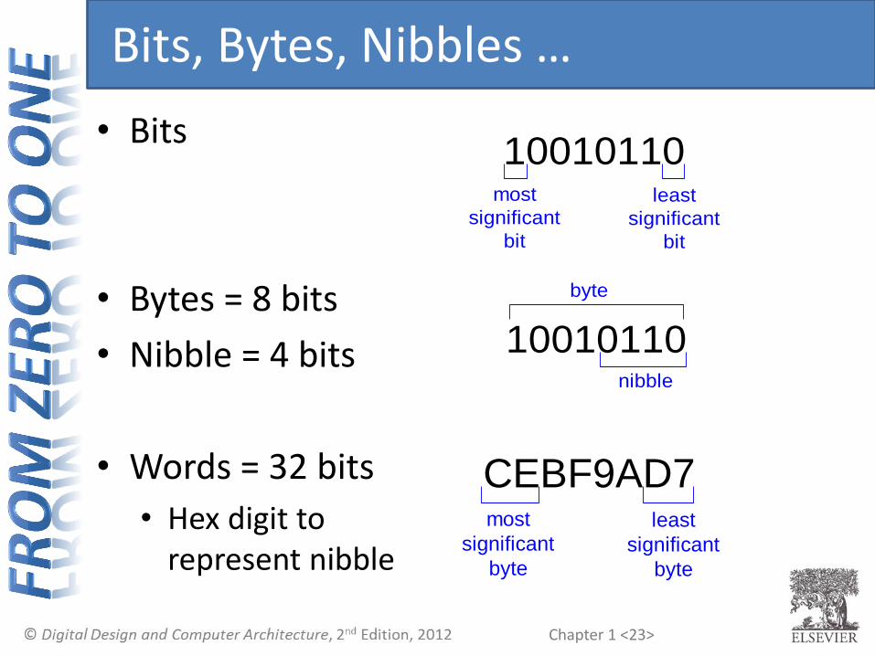
Bits, Bytes, Nibbles …
• Bits
• Bytes = 8 bits
• Nibble = 4 bits
• Words = 32 bits
• Hex digit to represent nibble
10010110least
significant
bit
most
significant
bit
10010110nibble
byte
CEBF9AD7least
significant
byte
most
significant
byte

Chapter 1 <24>
Decimal to Binary Conversion
• Two Methods:
• Method 1: Find largest power of 2 that fits, subtract and repeat
• Method 2: Repeatedly divide by 2, remainder goes in next most significant bit

Chapter 1 <25>
D2B: Method 1
• Find largest power of 2 that fits, subtract, repeat
5310

Chapter 1 <26>
D2B: Method 1
• Find largest power of 2 that fits, subtract, repeat
5310 5310 32×1
53-32 = 21 16×1
21-16 = 5 4×1
5-4 = 1 1×1
5310 32×1
53-32 = 21
5310 32×1
53-32 = 21 16×1
21-16 = 5
5310 32×1
53-32 = 21 16×1
21-16 = 5 4×1
5-4 = 1
= 1101012

Chapter 1 <27>
D2B: Method 2
• Repeatedly divide by 2, remainder goes in next most significant bit
5310 =

Chapter 1 <28>
D2B: Method 2
• Repeatedly divide by 2, remainder goes in next most significant bit
5310 = 5310 = 53/2 = 26 R1
5310 = 53/2 = 26 R1
26/2 = 13 R0
5310 = 53/2 = 26 R1
26/2 = 13 R0
13/2 = 6 R1
5310 = 53/2 = 26 R1
26/2 = 13 R0
13/2 = 6 R1
6/2 = 3 R0
5310 = 53/2 = 26 R1
26/2 = 13 R0
13/2 = 6 R1
6/2 = 3 R0
3/2 = 1 R1
5310 = 53/2 = 26 R1
26/2 = 13 R0
13/2 = 6 R1
6/2 = 3 R0
3/2 = 1 R1
1/2 = 0 R1
= 1101012
LSB
MSB

Chapter 1 <29>
Number Conversion
• Binary to decimal conversion
• Convert 100112 to decimal
• Decimal to binary conversion
• Convert 4710 to binary
32 × 1 + 16 × 0 + 8 × 1 + 4 × 1 + 2 × 1 + 1 × 1 = 1011112
16 × 1 + 8 × 0 + 4 × 0 + 2 × 1 + 1 × 1 = 1910

Chapter 1 <30>
D2B Example
• Convert 7510 to binary

Chapter 1 <31>
D2B Example
• Convert 7510 to binary
• Or
7510= 64 + 8 + 2 + 1 = 10010112
75/2 = 37 R1
37/2 = 18 R1
18/2 = 9 R0
9/2 = 4 R1
4/2 = 2 R0
2/2 = 1 R0
1/2 = 0 R1

Chapter 1 <32>
Binary Values and Range
• N-digit decimal number
• How many values?
• Range?
• Example: 3-digit decimal number
• Possible values
• Range

Chapter 1 <33>
Binary Values and Range
• N-digit decimal number
• How many values? • 10𝑁
• Range? • [0, 10𝑁 − 1]
• Example: 3-digit decimal number
• Possible values • 103 = 1000
• Range • [0, 999]

Chapter 1 <34>
Binary Values and Range
• N-bit binary number
• How many values?
• Range?
• Example: 3-bit binary number
• Possible values
• Range
Chapter 1 <35>
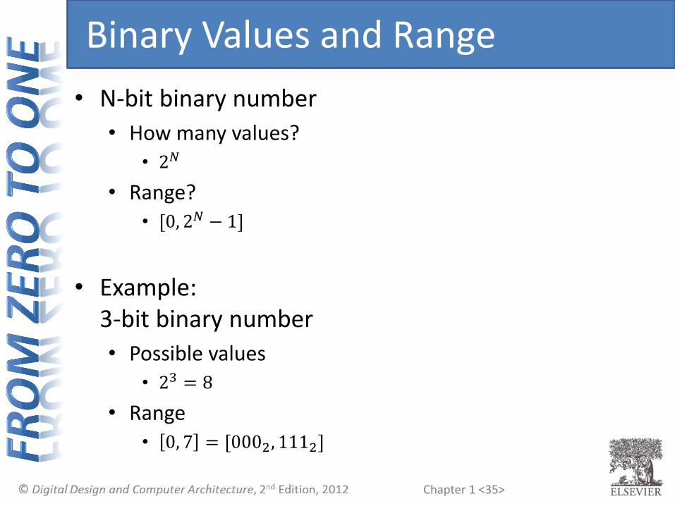
Binary Values and Range
• N-bit binary number
• How many values? • 2𝑁
• Range? • [0, 2𝑁 − 1]
• Example: 3-bit binary number
• Possible values • 23 = 8
• Range • 0, 7 = [0002, 1112]
Chapter 1 <36>
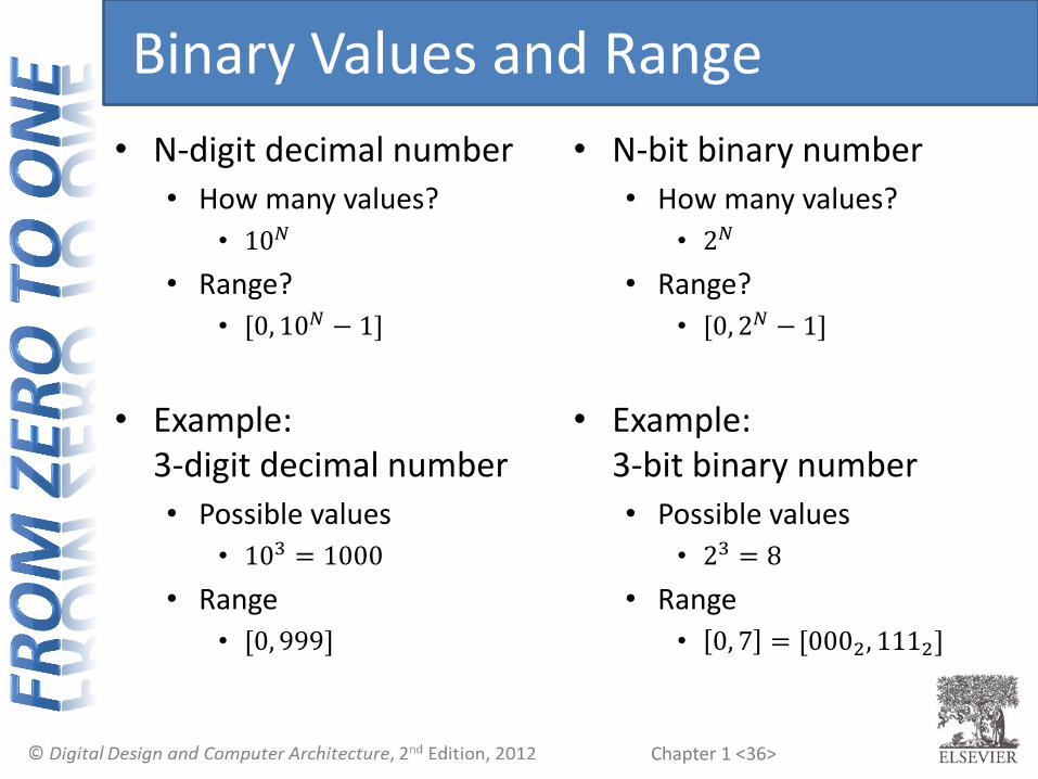
Binary Values and Range
• N-digit decimal number
• How many values?
• 10𝑁
• Range?
• [0, 10𝑁 − 1]
• Example: 3-digit decimal number
• Possible values
• 103 = 1000
• Range
• [0, 999]
• N-bit binary number
• How many values?
• 2𝑁
• Range?
• [0, 2𝑁 − 1]
• Example: 3-bit binary number
• Possible values
• 23 = 8
• Range
• 0, 7 = [0002, 1112]

Chapter 1 <37>
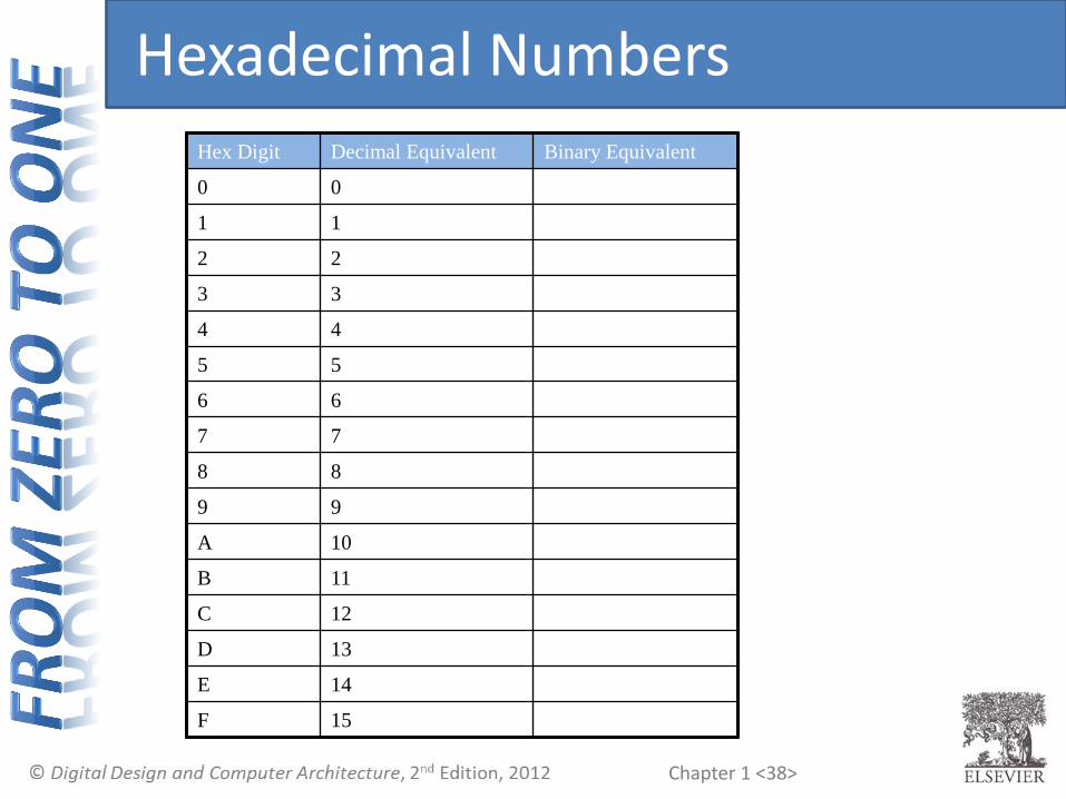
Hexadecimal Numbers
• Base 16 number system
• Shorthand for binary
• Four binary digits (4-bit binary number) is a single hex digit
Chapter 1 <38>
Hexadecimal Numbers
Hex Digit Decimal Equivalent Binary Equivalent
0 0
1 1
2 2
3 3
4 4
5 5
6 6
7 7
8 8
9 9
A 10
B 11
C 12
D 13
E 14
F 15

Chapter 1 <39>
Hexadecimal Numbers
Hex Digit Decimal Equivalent Binary Equivalent
0 0 0000
1 1 0001
2 2 0010
3 3 0011
4 4 0100
5 5 0101
6 6 0110
7 7 0111
8 8 1000
9 9 1001
A 10 1010
B 11 1011
C 12 1100
D 13 1101
E 14 1110
F 15 1111

Chapter 1 <40>
Hexadecimal to Binary Conversion
• Hexadecimal to binary conversion:
• Convert 4AF16 (also written 0x4AF) to binary
• Hexadecimal to decimal conversion:
• Convert 0x4AF to decimal

Chapter 1 <41>
Hexadecimal to Binary Conversion
• Hexadecimal to binary conversion:
• Convert 4AF16 (also written 0x4AF) to binary
• 0x4AF = 0100 1010 11112
• Hexadecimal to decimal conversion:
• Convert 0x4AF to decimal
• 4 × 162 + 10 × 161 + 15 × 160 = 119910

Chapter 1 <42>
Number Systems
• Popular
• Decima l Base 10
• Binary Base 2
• Hexadecimal Base 16
• Others
• Octal Base 8
• Any other base

Chapter 1 <43>
Octal Numbers
• Same as hex with one less binary digit
Octal Digit Decimal Equivalent Binary Equivalent
0 0 000
1 1 001
2 2 010
3 3 011
4 4 100
5 5 101
6 6 110
7 7 111

Chapter 1 <44>
Number Systems
• In general, an N-digit number {𝑎𝑁−1𝑎𝑁−2 … 𝑎1𝑎0} of base 𝑅 in decimal equals
• 𝑎𝑁−1𝑅𝑁−1 + 𝑎𝑁−2𝑅𝑁−2 + ⋯ + 𝑎1𝑅1 + 𝑎0𝑅0
• Example: 4-digit {5173} of base 8 (octal)

Chapter 1 <45>
Number Systems
• In general, an N-digit number {𝑎𝑁−1𝑎𝑁−2 … 𝑎1𝑎0} of base 𝑅 in decimal equals
• 𝑎𝑁−1𝑅𝑁−1 + 𝑎𝑁−2𝑅𝑁−2 + ⋯ + 𝑎1𝑅1 + 𝑎0𝑅0
• Example: 4-digit {5173} of base 8 (octal)
• 5 × 83 + 1 × 82 + 7 × 81 + 3 × 80 = 268310

Chapter 1 <46>
Decimal to Octal Conversion
• Remember two methods for D2B conversion
• 1: remove largest multiple; 2: repeated divide
• Convert 2910 to octal
Chapter 1 <47>
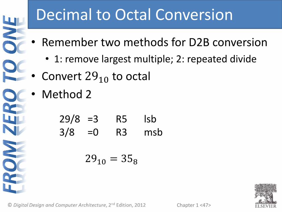
Decimal to Octal Conversion
• Remember two methods for D2B conversion
• 1: remove largest multiple; 2: repeated divide
• Convert 2910 to octal
• Method 2
29/8 =3 R5 lsb 3/8 =0 R3 msb
2910 = 358

Chapter 1 <48>
Decimal to Octal Conversion
• Remember two methods for D2B conversion
• 1: remove largest multiple; 2: repeated divide
• Convert 2910 to octal
• Method 1
• Or (better scalability)
29 8×3=24 29-24=5 2910 = 24 + 5 = 3 × 81 + 5 × 80 = 358
2910 = 16 + 8 + 4 + 1 = 111012 = 358

Chapter 1 <49>
Octal to Decimal Conversion
• Convert 1638 to decimal
Chapter 1 <50>
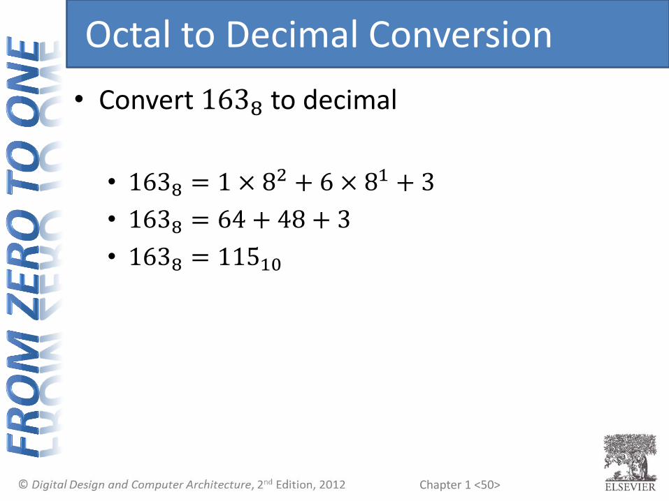
Octal to Decimal Conversion
• Convert 1638 to decimal
• 1638 = 1 × 82 + 6 × 81 + 3
• 1638 = 64 + 48 + 3
• 1638 = 11510

Chapter 1 <51>
Recap: Binary and Hex Numbers
• Example 1: Convert 8310 to hex
• Example 2: Convert 011010112 to hex and decimal
• Example 3: Convert 0xCA3 to binary and decimal
Chapter 1 <52>
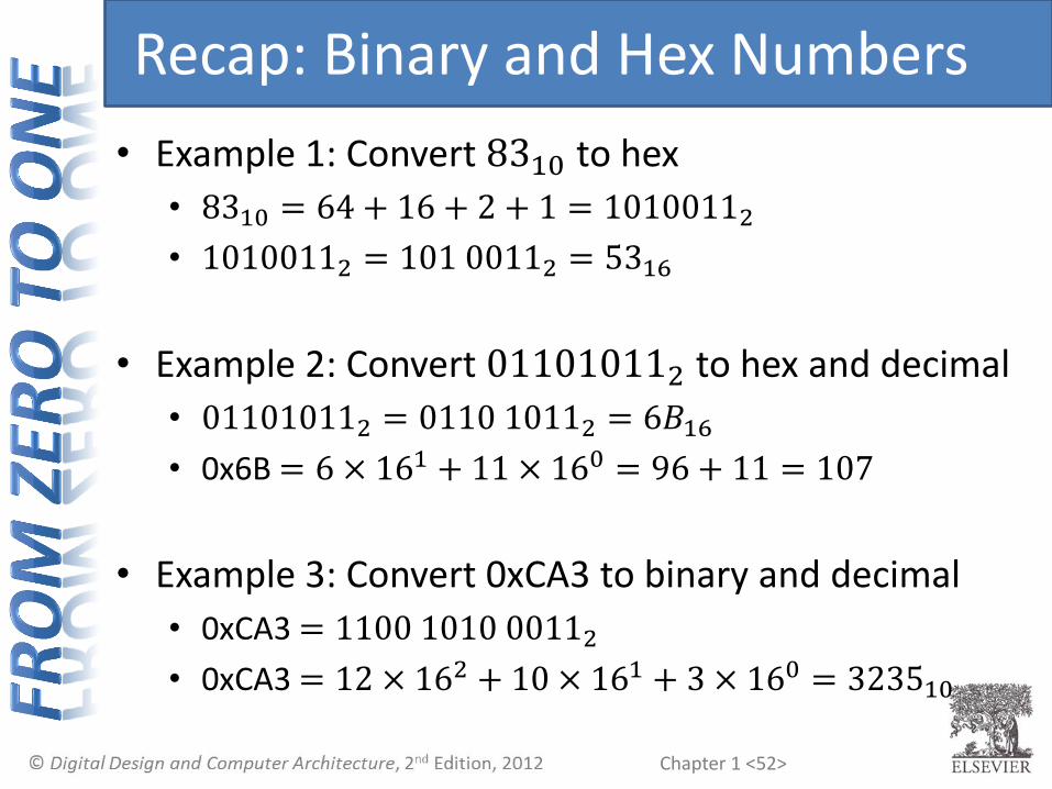
Recap: Binary and Hex Numbers
• Example 1: Convert 8310 to hex
• 8310 = 64 + 16 + 2 + 1 = 10100112
• 10100112 = 101 00112 = 5316
• Example 2: Convert 011010112 to hex and decimal
• 011010112 = 0110 10112 = 6𝐵16
• 0x6B = 6 × 161 + 11 × 160 = 96 + 11 = 107
• Example 3: Convert 0xCA3 to binary and decimal
• 0xCA3 = 1100 1010 00112
• 0xCA3 = 12 × 162 + 10 × 161 + 3 × 160 = 323510

Chapter 1 <53>
Large Powers of Two
• 210 = 1 kilo ≈ 1000 (1024)
• 220 = 1 mega ≈ 1 million (1,048,576)
• 230 = 1 giga ≈ 1 billion (1,073,741,824)
• 240 = 1 tera ≈ 1 trillion (1,099,511,627,776)

Chapter 1 <54>
Large Powers of Two: Abbreviations
• 210 = 1 kilo ≈ 1000 (1024)
for example: 1 kB = 1024 Bytes
1 kb = 1024 bits
• 220 = 1 mega ≈ 1 million (1,048,576)
for example: 1 MiB, 1 Mib (1 megabit)
• 230 = 1 giga ≈ 1 billion (1,073,741,824)
for example: 1 GiB, 1 Gib
Chapter 1 <55>
Estimating Powers of Two
• What is the value of 224?
• How many values can a 32-bit variable represent?

Chapter 1 <56>
Estimating Powers of Two
• What is the value of 224?
• 24 × 220 ≈ 16 million
• How many values can a 32-bit variable represent?
• 22 × 230 ≈ 4 billion
Chapter 1 <57>
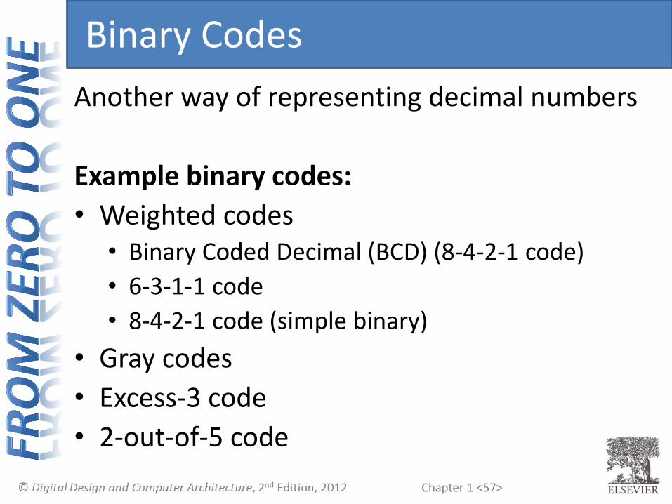
Binary Codes
Another way of representing decimal numbers
Example binary codes:
• Weighted codes • Binary Coded Decimal (BCD) (8-4-2-1 code)
• 6-3-1-1 code
• 8-4-2-1 code (simple binary)
• Gray codes
• Excess-3 code
• 2-out-of-5 code

Chapter 1 <58>
Binary Codes
Decimal # 8-4-2-1 (BCD)
6-3-1-1 Excess-3 2-out-of-5 Gray
0 0000 0000 0011 00011 0000
1 0001 0001 0100 00101 0001
2 0010 0011 0101 00110 0011
3 0011 0100 0110 01001 0010
4 0100 0101 0111 01010 0110
5 0101 0111 1000 01100 1110
6 0110 1000 1001 10001 1010
7 0111 1001 1010 10010 1011
8 1000 1011 1011 10100 1001
9 1001 1100 1100 11000 1000
Each code combination represents a single decimal digit.

Chapter 1 <59>
Weighted Codes
• Weighted codes: each bit position has a given weight
• Binary Coded Decimal (BCD) (8-4-2-1 code)
• Example: 72610 = 0111 0010 0110BCD
• 6-3-1-1 code
• Example: 1001 (6-3-1-1 code) = 1×6 + 0×3 + 0×1 + 1×1
• Example: 72610 = 1001 0011 10006311
• BCD numbers are used to represent fractional numbers exactly (vs. floating point numbers – which can’t - see Chapter 5)

Chapter 1 <60>
Weighted Codes
• BCD Example:
72610 = 0111 0010 0110BCD
• 6-3-1-1 code Example:
72610 = 1001 0011 10006311
Decimal # 8-4-2-1 (BCD)
6-3-1-1
0 0000 0000
1 0001 0001
2 0010 0011
3 0011 0100
4 0100 0101
5 0101 0111
6 0110 1000
7 0111 1001
8 1000 1011
9 1001 1100
Chapter 1 <61>
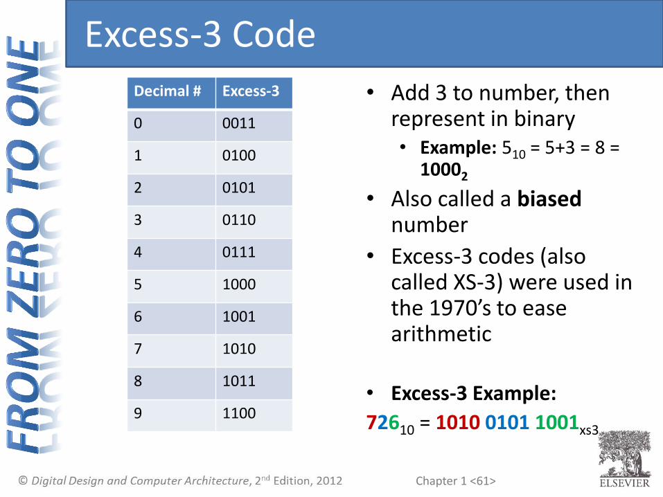
Excess-3 Code
• Add 3 to number, then represent in binary • Example: 510 = 5+3 = 8 =
10002
• Also called a biased number
• Excess-3 codes (also called XS-3) were used in the 1970’s to ease arithmetic
• Excess-3 Example:
72610 = 1010 0101 1001xs3
Decimal # Excess-3
0 0011
1 0100
2 0101
3 0110
4 0111
5 1000
6 1001
7 1010
8 1011
9 1100

Chapter 1 <62>
2-out-of-5 Code
• 2 out of the 5 bits are 1
• Used for error detection:
• If more or less than 2 of 5 bits are 1, error
Decimal # 2-out-of-5
0 00011
1 00101
2 00110
3 01001
4 01010
5 01100
6 10001
7 10010
8 10100
9 11000

Chapter 1 <63>
Gray Codes
• Next number differs in only one bit position
• Example: 000, 001, 011, 010, 110, 111, 101, 100
• Example use: Analog-to-Digital (A/D) converters. Changing 2 bits at a time (i.e., 011 →100) could cause large inaccuracies.
Decimal # Gray
0 0000
1 0001
2 0011
3 0010
4 0110
5 1110
6 1010
7 1011
8 1001
9 1000

Chapter 1 <64>
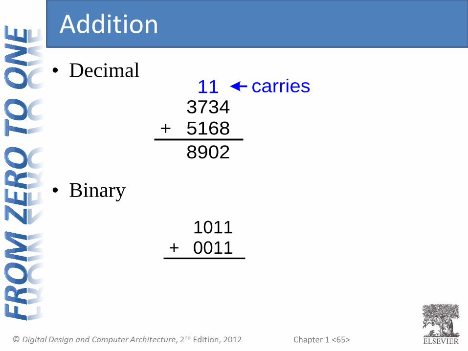
Addition
• Decimal
• Binary
37345168+
10110011+
Chapter 1 <65>
• Decimal
• Binary
37345168+
8902
carries 11
10110011+
Addition

Chapter 1 <66>
• Decimal
• Binary
37345168+
8902
carries 11
10110011+
1110
11 carries
Addition

Chapter 1 <67>
Binary Addition Examples
• Add the following 4-bit
binary numbers
• Add the following 4-bit
binary numbers
10010101+
10110110+

Chapter 1 <68>
Binary Addition Examples
• Add the following 4-bit
binary numbers
• Add the following 4-bit
binary numbers
10010101+
1110
1
10110110+

Chapter 1 <69>
Binary Addition Examples
• Add the following 4-bit
binary numbers
• Add the following 4-bit
binary numbers
10010101+
1110
1
10110110+
10001
111
Overflow!

Chapter 1 <70>
Overflow
• Digital systems operate on a fixed number of
bits
• Overflow: when result is too big to fit in the
available number of bits
• See previous example of 11 + 6

Chapter 1 <71>
Signed Binary Numbers
• Sign/Magnitude Numbers
• Two’s Complement Numbers
Chapter 1 <72>
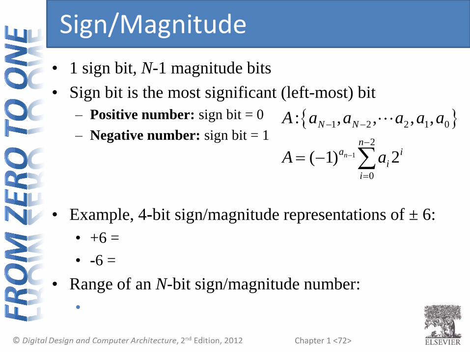
Sign/Magnitude
• 1 sign bit, N-1 magnitude bits
• Sign bit is the most significant (left-most) bit
– Positive number: sign bit = 0
– Negative number: sign bit = 1
• Example, 4-bit sign/magnitude representations of ± 6:
• +6 =
• -6 =
• Range of an N-bit sign/magnitude number:
•
1
1 2 2 1 0
2
0
: , , , ,
( 1) 2n
N N
na i
i
i
A a a a a a
A a

Chapter 1 <73>
Sign/Magnitude
• 1 sign bit, N-1 magnitude bits
• Sign bit is the most significant (left-most) bit
– Positive number: sign bit = 0
– Negative number: sign bit = 1
• Example, 4-bit sign/magnitude representations of ± 6:
• +6 = 0110
• -6 = 1110
• Range of an N-bit sign/magnitude number:
• [-(2N-1-1), 2N-1-1]
1
1 2 2 1 0
2
0
: , , , ,
( 1) 2n
N N
na i
i
i
A a a a a a
A a

Chapter 1 <74>
Sign/Magnitude Numbers
• Problems:
• Addition doesn’t work, for example -6 + 6:
1110
+ 0110
• Two representations of 0 (± 0):
• +0 =
• −0 =

Chapter 1 <75>
Sign/Magnitude Numbers
• Problems:
• Addition doesn’t work, for example -6 + 6:
1110
+ 0110
10100 (wrong!)
• Two representations of 0 (± 0):
• +0 = 0000
• −0 = 1000
Chapter 1 <76>
Two’s Complement Numbers
• Don’t have same problems as sign/magnitude numbers:
• Addition works
• Single representation for 0
• Range of representable numbers not symmetric
• One extra negative number
Chapter 1 <77>
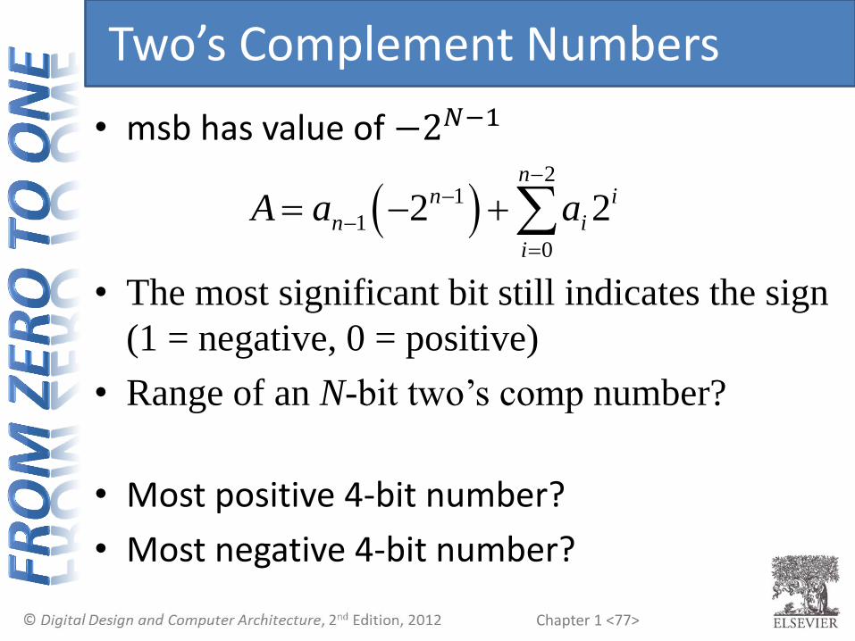
Two’s Complement Numbers
• msb has value of −2𝑁−1
• The most significant bit still indicates the sign
(1 = negative, 0 = positive)
• Range of an N-bit two’s comp number?
• Most positive 4-bit number?
• Most negative 4-bit number?
2
1
1
0
2 2n
n i
n i
i
A a a

Chapter 1 <78>
Two’s Complement Numbers
• msb has value of −2𝑁−1
• The most significant bit still indicates the sign
(1 = negative, 0 = positive)
• Range of an N-bit two’s comp number?
• [− 2𝑁−1 , 2N−1 − 1]
• Most positive 4-bit number?
• Most negative 4-bit number?
2
1
1
0
2 2n
n i
n i
i
A a a
0111
1000

Chapter 1 <79>
“Taking the Two’s Complement”
• Flips the sign of a two’s complement
number
• Method: 1. Invert the bits
2. Add 1
• Example: Flip the sign of 310 = 00112

Chapter 1 <80>
“Taking the Two’s Complement”
• Flips the sign of a two’s complement
number
• Method: 1. Invert the bits
2. Add 1
• Example: Flip the sign of 310 = 00112
1. 1100
2. + 1
1101 = -310
Chapter 1 <81>
Two’s Complement Examples
• Take the two’s complement of 610 = 01102
• What is the decimal value of the two’s
complement number 10012?
Chapter 1 <82>
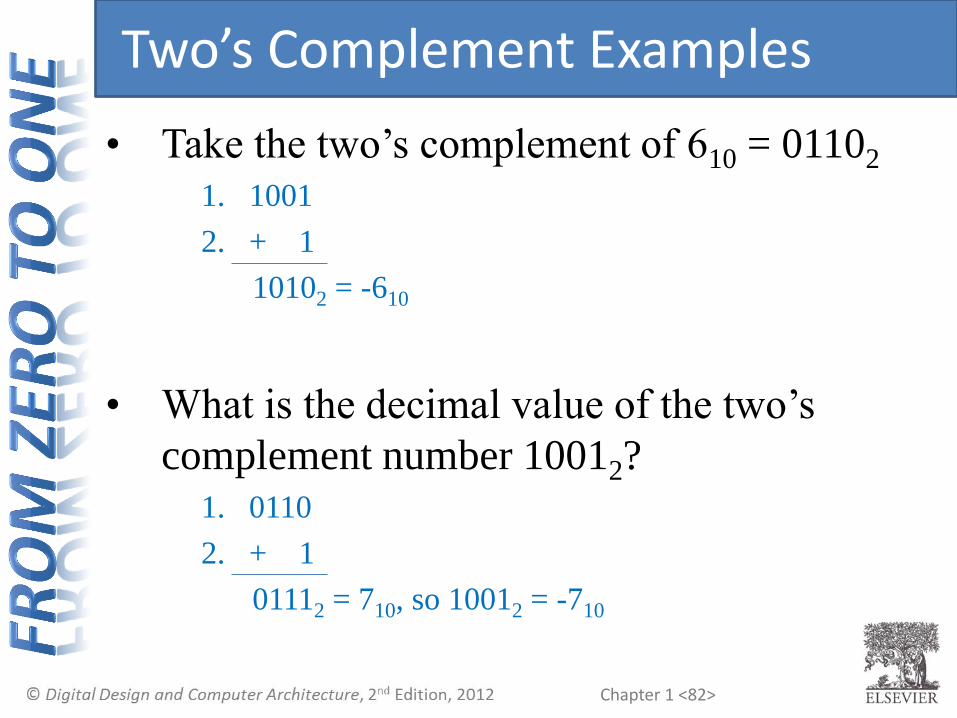
Two’s Complement Examples
• Take the two’s complement of 610 = 01102
1. 1001
2. + 1
10102 = -610
• What is the decimal value of the two’s
complement number 10012? 1. 0110
2. + 1
01112 = 710, so 10012 = -710

Chapter 1 <83>
Two’s Complement Addition
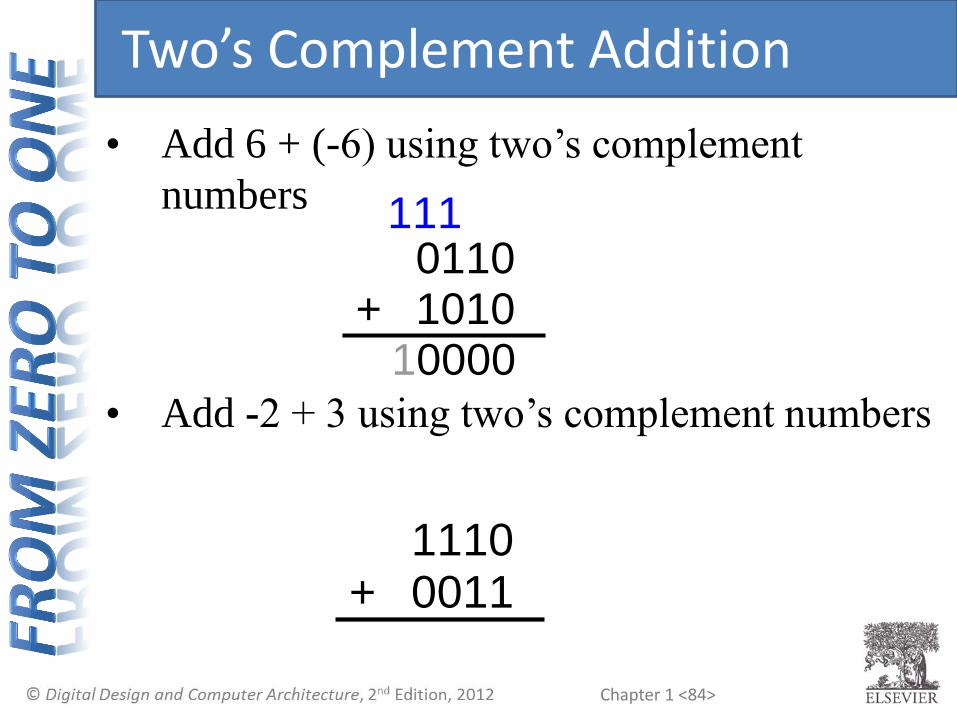
• Add 6 + (-6) using two’s complement
numbers
• Add -2 + 3 using two’s complement numbers
+11100011
+01101010
Chapter 1 <84>
Two’s Complement Addition
• Add 6 + (-6) using two’s complement
numbers
• Add -2 + 3 using two’s complement numbers
+01101010
10000
111
+11100011

Chapter 1 <85>
Two’s Complement Addition
• Add 6 + (-6) using two’s complement
numbers
• Add -2 + 3 using two’s complement numbers
+11100011
10001
111
+01101010
10000
111

Chapter 1 <86>
Increasing Bit Width
• Extend number from N to M bits (M > N) :
• Sign-extension
• Zero-extension

Chapter 1 <87>
Sign-Extension
• Sign bit copied to msb’s
• Number value is same
• Example 1
• 4-bit representation of 3 = 0011
• 8-bit sign-extended value:
• Example 2
• 4-bit representation of -7 = 1001
• 8-bit sign-extended value:

Chapter 1 <88>
Sign-Extension
• Sign bit copied to msb’s
• Number value is same
• Example 1
• 4-bit representation of 3 = 0011
• 8-bit sign-extended value: 00000011
• Example 2
• 4-bit representation of -7 = 1001
• 8-bit sign-extended value: 11111001
Chapter 1 <89>
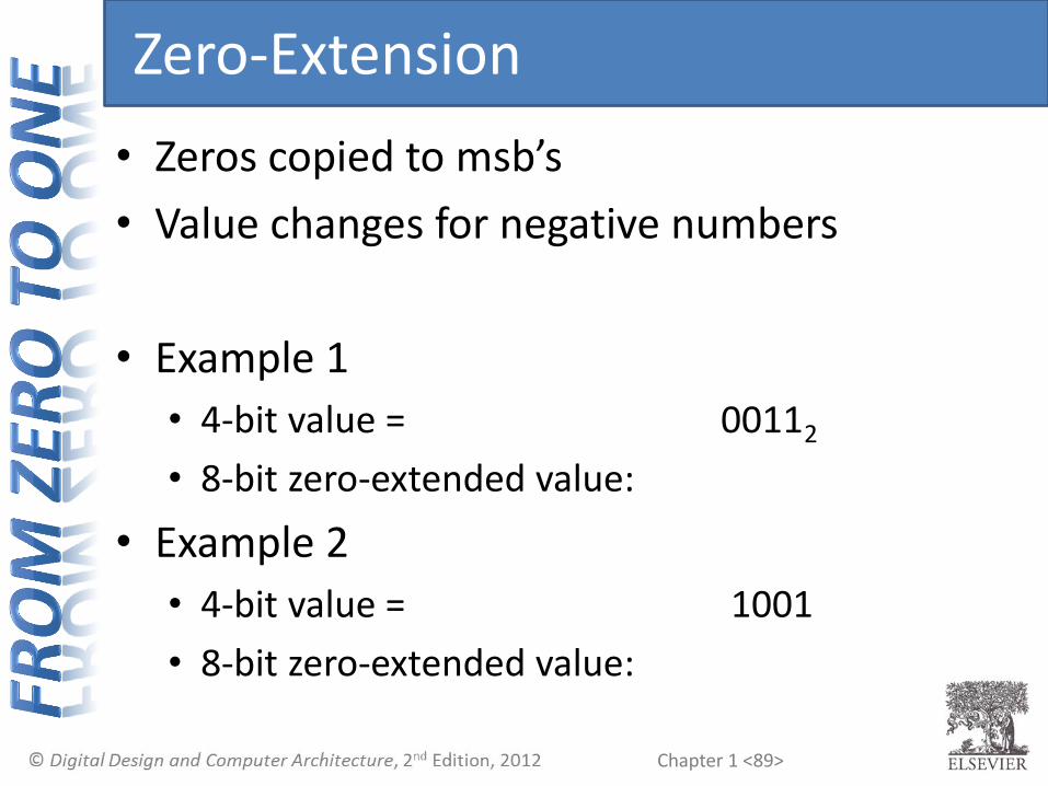
Zero-Extension
• Zeros copied to msb’s
• Value changes for negative numbers
• Example 1
• 4-bit value = 00112 • 8-bit zero-extended value:
• Example 2
• 4-bit value = 1001 • 8-bit zero-extended value:
Chapter 1 <90>
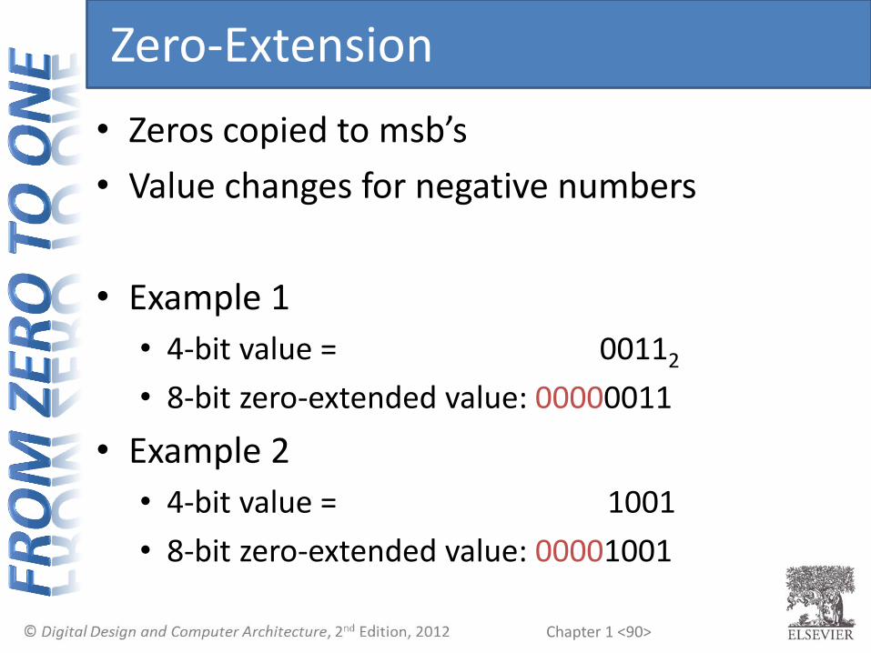
Zero-Extension
• Zeros copied to msb’s
• Value changes for negative numbers
• Example 1
• 4-bit value = 00112 • 8-bit zero-extended value: 00000011
• Example 2
• 4-bit value = 1001 • 8-bit zero-extended value: 00001001

Chapter 1 <91>
Zero-Extension
• Zeros copied to msb’s
• Value changes for negative numbers
• Example 1
• 4-bit value = 00112 = 310
• 8-bit zero-extended value: 00000011 = 310
• Example 2
• 4-bit value = 1001 = -710
• 8-bit zero-extended value: 00001001 = 910

Chapter 1 <92>
Number System Comparison
-8
1000 1001
-7 -6 -5 -4 -3 -2 -1 0 1 2 3 4 5 6 7 8 9 10 11 12 13 14 15
1010 1011 1100 1101 1110 1111 0000 0001 0010 0011 0100 0101 0110 0111 Two's Complement
10001001101010111100110111101111
00000001 0010 0011 0100 0101 0110 0111
1000 1001 1010 1011 1100 1101 1110 11110000 0001 0010 0011 0100 0101 0110 0111
Sign/Magnitude
Unsigned
Number System Range
Unsigned [0, 2N-1]
Sign/Magnitude [-(2N-1-1), 2N-1-1]
Two’s Complement [-2N-1, 2N-1-1]
For example, 4-bit representation:
Chapter 1 <93>
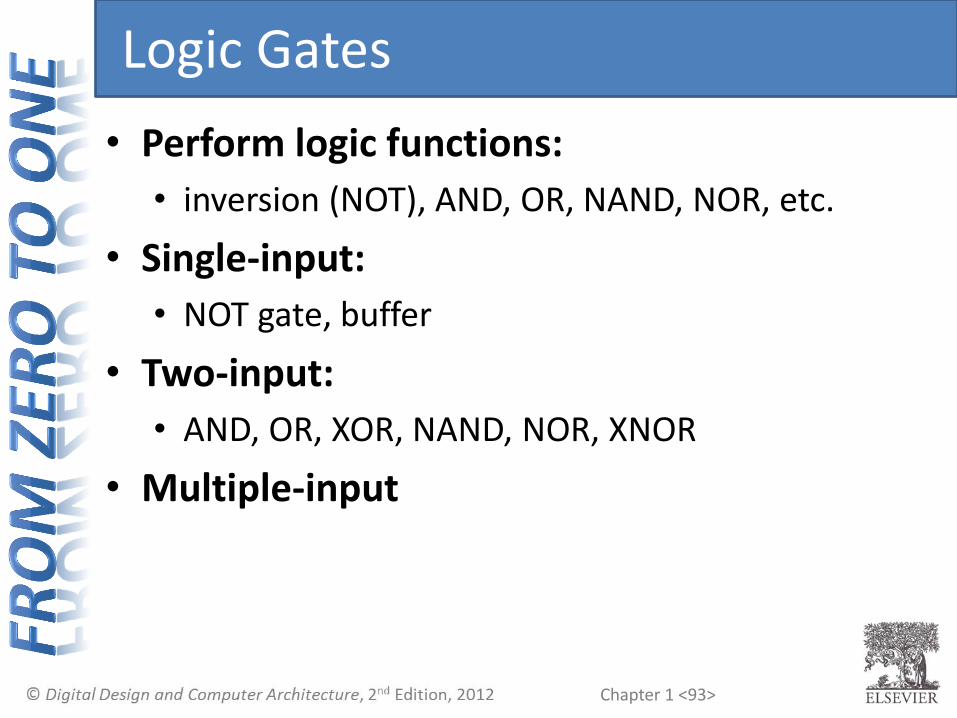
Logic Gates
• Perform logic functions:
• inversion (NOT), AND, OR, NAND, NOR, etc.
• Single-input:
• NOT gate, buffer
• Two-input:
• AND, OR, XOR, NAND, NOR, XNOR
• Multiple-input

Chapter 1 <94>
Single-Input Logic Gates
NOT
Y = A
A Y0
1
A Y
BUF
Y = A
A Y0
1
A Y
Chapter 1 <95>
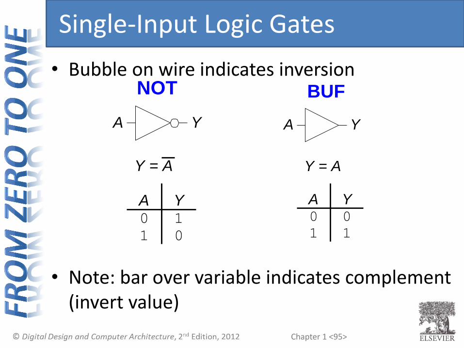
Single-Input Logic Gates
• Bubble on wire indicates inversion
• Note: bar over variable indicates complement (invert value)
NOT
Y = A
A Y0 1
1 0
A Y
BUF
Y = A
A Y0 0
1 1
A Y

Chapter 1 <96>
Two-Input Logic Gates
AND
Y = AB
A B Y0 0
0 1
1 0
1 1
AB
Y
OR
Y = A + B
A B Y0 0
0 1
1 0
1 1
AB
Y

Chapter 1 <97>
Two-Input Logic Gates
AND
Y = AB
A B Y0 0 0
0 1 0
1 0 0
1 1 1
AB
Y
OR
Y = A + B
A B Y0 0 0
0 1 1
1 0 1
1 1 1
AB
Y
Chapter 1 <98>
More Two-Input Logic Gates
XNOR
Y = A + B
A B Y0 0
0 1
1 0
1 1
AB
Y
XOR NAND NOR
Y = A + B Y = AB Y = A + B
A B Y0 0
0 1
1 0
1 1
A B Y0 0
0 1
1 0
1 1
A B Y0 0
0 1
1 0
1 1
AB
YAB
YAB
Y

Chapter 1 <99>
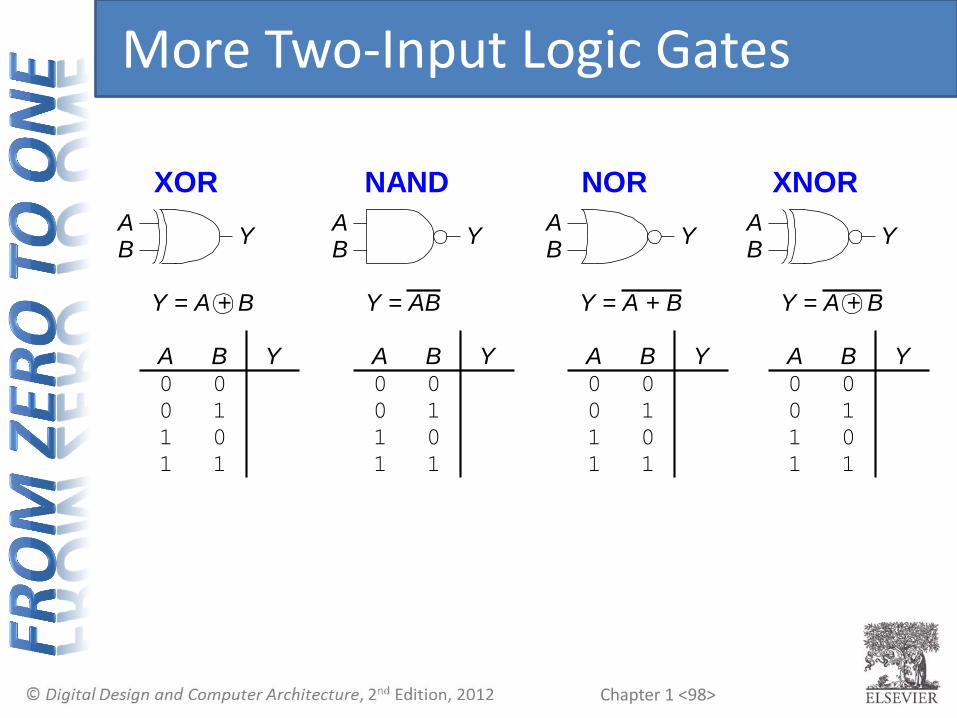
More Two-Input Logic Gates
XNOR
Y = A + B
A B Y0 0
0 1
1 0
1 1
AB
Y
XOR NAND NOR
Y = A + B Y = AB Y = A + B
A B Y0 0 0
0 1 1
1 0 1
1 1 0
A B Y0 0 1
0 1 1
1 0 1
1 1 0
A B Y0 0 1
0 1 0
1 0 0
1 1 0
AB
YAB
YAB
Y
1
0
0
1

Chapter 1 <100>
Multiple-Input Logic Gates
NOR3
Y = A+B+C
B C Y0 0
0 1
1 0
1 1
AB YC
A0
0
0
0
0 0
0 1
1 0
1 1
1
1
1
1
AND3
Y = ABC
AB YC
B C Y0 0
0 1
1 0
1 1
A0
0
0
0
0 0
0 1
1 0
1 1
1
1
1
1

Chapter 1 <101>
Multiple-Input Logic Gates
• Multi-input XOR = Odd parity (one for odd input=1)
AND3
Y = ABC
AB YC
B C Y0 0
0 1
1 0
1 1
A0
0
0
0
0 0
0 1
1 0
1 1
1
1
1
1
0
0
0
0
0
0
0
1
NOR3
Y = A+B+C
B C Y0 0
0 1
1 0
1 1
AB YC
A0
0
0
0
0 0
0 1
1 0
1 1
1
1
1
1
1
0
0
0
0
0
0
0

Chapter 1 <102>
Logic Levels
• Discrete voltages represent 1 and 0
• For example:
• 0 = ground (GND) or 0 volts
• 1 = VDD or 5 volts
• What about 4.99 volts? Is that a 0 or a 1?
• What about 3.2 volts?

Chapter 1 <103>
Logic Levels
• Must have range of voltages for 1 and 0
• Different ranges for inputs and outputs to allow for noise

Chapter 1 <104>
What is Noise?
• Anything that degrades the signal
• E.g., resistance, power supply noise, coupling to neighboring wires, etc.
• Example: a gate (driver) outputs 5 V but, because of resistance in a long wire, receiver gets 4.5 V
Driver ReceiverNoise
5 V 4.5 V

Chapter 1 <105>
The Static Discipline
• With logically valid inputs, every circuit element must produce logically valid outputs
• Use limited ranges of voltages to represent discrete values

Chapter 1 <106>
Real Logic Levels
• Want driver to output “clean” high/low and receiver to handle noisy high/low
Driver Receiver

Chapter 1 <107>
Real Logic Levels
• Want driver to output “clean” high/low and receiver to handle noisy high/low
Driver Receiver
Forbidden
Zone
NML
NMH
Input CharacteristicsOutput Characteristics
VO H
VDD
VO L
GND
VIH
VIL
Logic High
Input Range
Logic Low
Input Range
Logic High
Output Range
Logic Low
Output Range

Chapter 1 <108>
Real Logic Levels
Forbidden
Zone
NML
NMH
Input CharacteristicsOutput Characteristics
VO H
VDD
VO L
GND
VIH
VIL
Logic High
Input Range
Logic Low
Input Range
Logic High
Output Range
Logic Low
Output Range
Driver Receiver
NMH = VOH – VIH
NML = VIL – VOL

Chapter 1 <109>
VDD Scaling
• In 1970’s and 1980’s, VDD = 5 V
• VDD has dropped • 3.3 V, 2.5 V, 1.8 V, 1.5 V, 1.2 V, 1.0 V, …
• Avoid frying tiny transistors
• Save power
• Be careful connecting chips with different supply voltages • Easy to fry if not careful

Chapter 1 <110>
Logic Family Examples
Logic Family VDD VIL VIH VOL VOH
TTL 5 (4.75 - 5.25) 0.8 2.0 0.4 2.4
CMOS 5 (4.5 - 6) 1.35 3.15 0.33 3.84
LVTTL 3.3 (3 - 3.6) 0.8 2.0 0.4 2.4
LVCMOS 3.3 (3 - 3.6) 0.9 1.8 0.36 2.7

Chapter 1 <111>
Transistors
• Logic gates built from transistors
• Simple model: 3-ported voltage-controlled switch
• 2 ports connected depending on voltage of 3rd
• d and s are connected (ON) when g is 1
g
s
d
g = 0
s
d
g = 1
s
d
OFF ON
Chapter 1 <112>
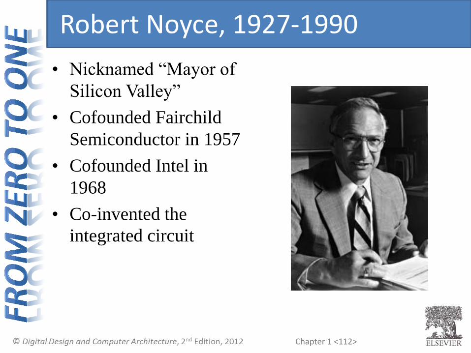
Robert Noyce, 1927-1990
• Nicknamed “Mayor of
Silicon Valley”
• Cofounded Fairchild
Semiconductor in 1957
• Cofounded Intel in
1968
• Co-invented the
integrated circuit

Chapter 1 <113>
Silicon
• Transistors built from silicon, a semiconductor
• Pure silicon is a poor conductor (no free charges)
• Doped silicon is a good conductor (free charges) • n-type (free negative charges, electrons)
• p-type (free positive charges, holes)
Silicon Lattice
Si SiSi
Si SiSi
Si SiSi
As SiSi
Si SiSi
Si SiSi
B SiSi
Si SiSi
Si SiSi
-
+
+
-
Free electron Free hole
n-Type p-Type
Chapter 1 <114>
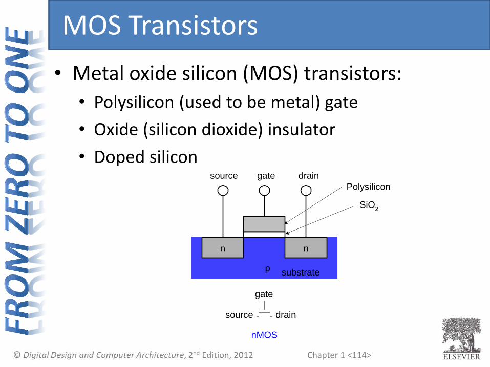
MOS Transistors
• Metal oxide silicon (MOS) transistors:
• Polysilicon (used to be metal) gate
• Oxide (silicon dioxide) insulator
• Doped silicon
n
p
gatesource drain
substrate
SiO2
nMOS
Polysilicon
n
gate
source drain

Chapter 1 <115>
nMOS Transistors
• Gate = 0
• OFF (no connection between source and drain)
• Gate = 1
• ON (channel between source and drain)
n
p
gate
source drain
substrate
n n
p
gatesource drain
substrate
n
GND
GND
VDD
GND
+++++++
- - - - - - -
channel
Diode connection from p to n doped area current cannot travel from np
Chapter 1 <116>
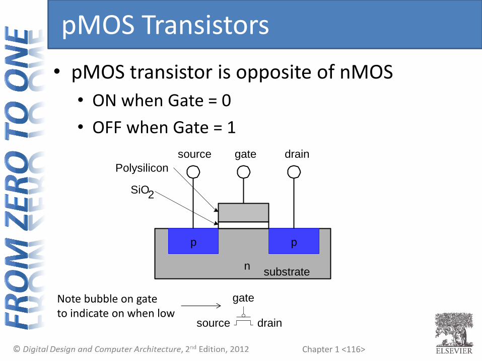
pMOS Transistors
• pMOS transistor is opposite of nMOS
• ON when Gate = 0
• OFF when Gate = 1
SiO2
n
gatesource drain
Polysilicon
p p
gate
source drain
substrate
Note bubble on gate to indicate on when low

Chapter 1 <117>
Transistor Function
• Voltage controlled switch
g
s
d
g = 0
s
d
g = 1
s
d
g
d
s
d
s
d
s
nMOS
pMOS
OFFON
ONOFF

Chapter 1 <118>
Transistor Composition
• nMOS: pass good 0’s
• Connect source to GND
• “Pull down” transistor
• pMOS: pass good 1’s
• Connect source to VDD
• “Pull up” transistor
• Build logic gates from composition
• CMOS = complementary MOS
pMOS
pull-up
network
output
inputs
nMOS
pull-down
network

Chapter 1 <119>
CMOS Gate Structure
• Pull-up pMOS network connects to 𝑉𝐷𝐷
• Pull-down nMOS network connects to 𝐺𝑁𝐷
• Use series and parallel connections to implement gate logic
pMOS
pull-up
network
output
inputs
nMOS
pull-down
network

Chapter 1 <120>
CMOS Gates: NOT Gate
V
DD
A Y
GND
N1
P1
NOT
Y = A
A Y0 1
1 0
A Y
A P1 N1 Y
0
1
Chapter 1 <121>
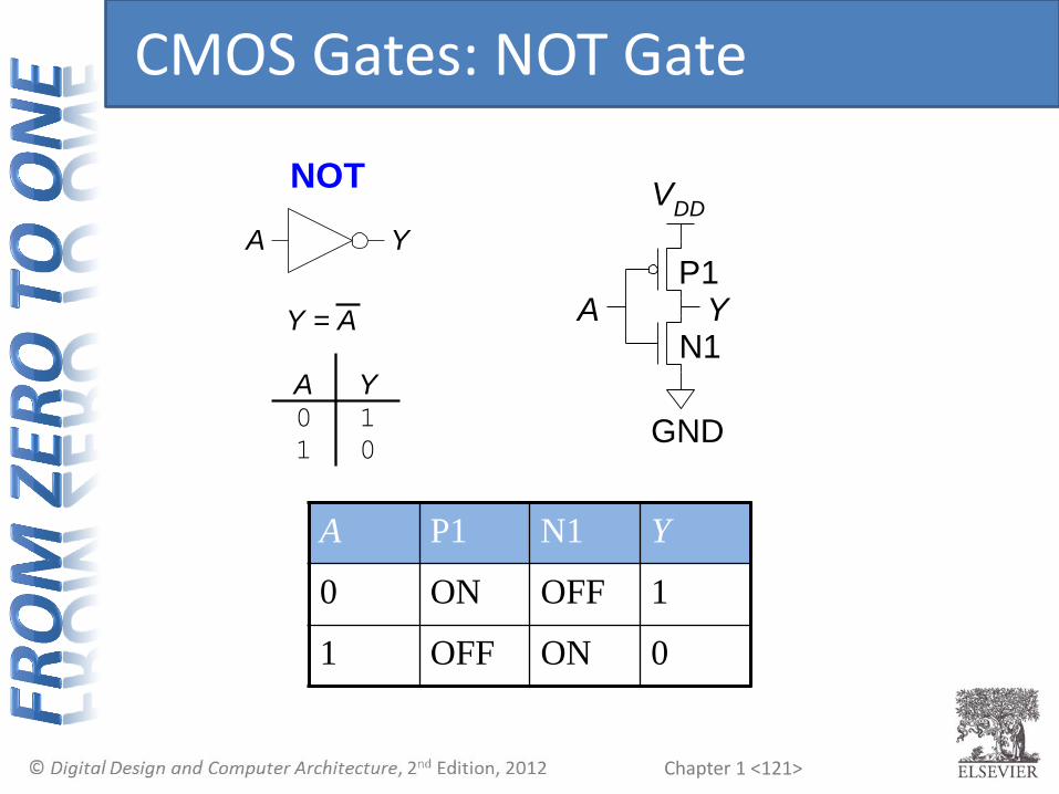
CMOS Gates: NOT Gate
V
DD
A Y
GND
N1
P1
NOT
Y = A
A Y0 1
1 0
A Y
A P1 N1 Y
0 ON OFF 1
1 OFF ON 0

Chapter 1 <122>
CMOS Gates: NAND Gate
A
B
Y
N2
N1
P2 P1
NAND
Y = AB
A B Y0 0 1
0 1 1
1 0 1
1 1 0
AB
Y
A B P1 P2 N1 N2 Y
0 0
0 1
1 0
1 1

Chapter 1 <123>
CMOS Gates: NAND Gate
A
B
Y
N2
N1
P2 P1
NAND
Y = AB
A B Y0 0 1
0 1 1
1 0 1
1 1 0
AB
Y
A B P1 P2 N1 N2 Y
0 0 ON ON OFF OFF 1
0 1 ON OFF OFF ON 1
1 0 OFF ON ON OFF 1
1 1 OFF OFF ON ON 0

Chapter 1 <124>
CMOS Gates: NOR Gate
• How can you build three input 𝐴, 𝐵, 𝐶 NOR gate?

Chapter 1 <125>
CMOS Gates: NOR Gate
• How can you build three input 𝐴, 𝐵, 𝐶 NOR gate?
B
CY
A Only high output when all three pMOS in series are “on” and create a path from output to 𝑉𝐷𝐷

Chapter 1 <126>
CMOS Gates: AND Gate
• How can you build 2 input AND gate?

Chapter 1 <127>
CMOS Gates: AND Gate
• How can you build 2 input AND gate?
AB
Y
Chapter 1 <128>
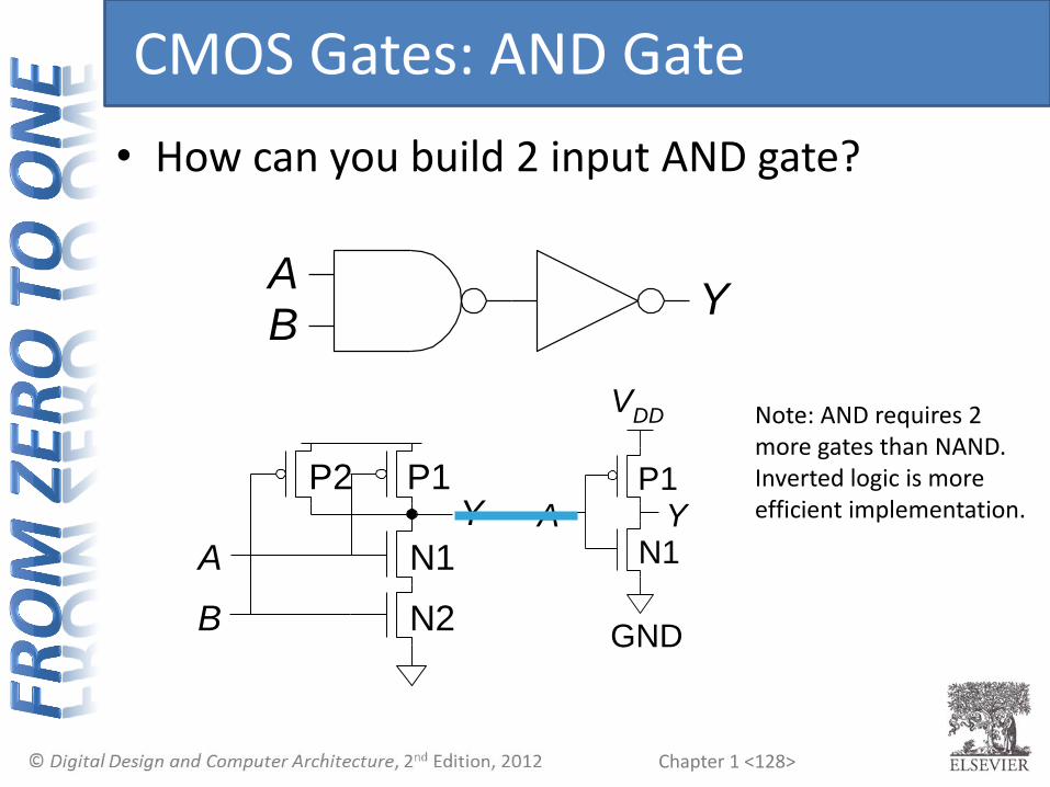
CMOS Gates: AND Gate
• How can you build 2 input AND gate?
AB
Y
A
B
Y
N2
N1
P2 P1
VDD
A Y
GND
N1
P1
Note: AND requires 2 more gates than NAND. Inverted logic is more efficient implementation.

Chapter 1 <129>
Transmission Gates
• nMOS pass 1’s poorly, pMOS pass 0’s poorly
• Transmission gate is for passing signal
• Pass both 0 and 1 well
• When EN = 1, the switch is ON:
• 𝐸𝑁 = 0 and A is connected to B
• When EN = 0, the switch is OFF:
• A is not connected to B
A B
EN
EN
Chapter 1 <130>
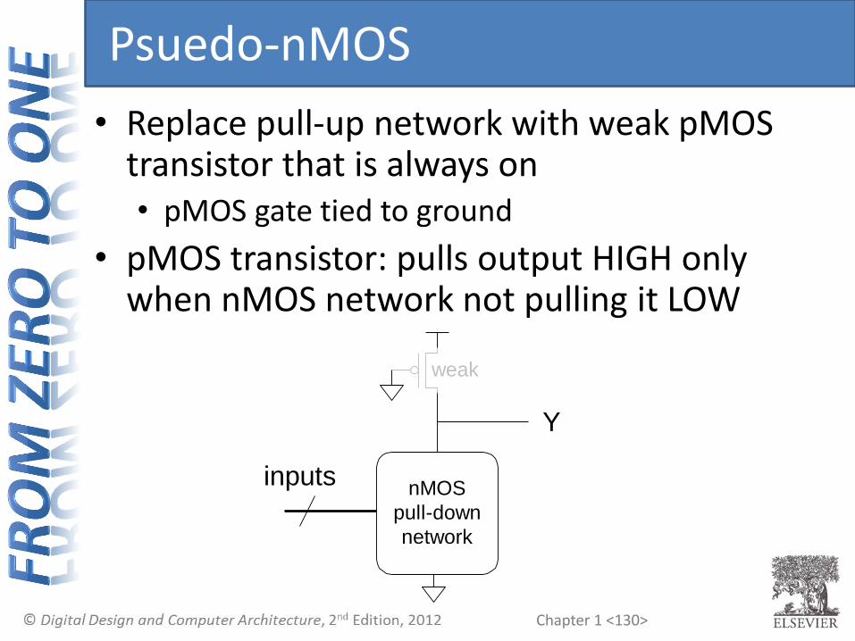
Psuedo-nMOS
• Replace pull-up network with weak pMOS transistor that is always on • pMOS gate tied to ground
• pMOS transistor: pulls output HIGH only when nMOS network not pulling it LOW
Y
inputsnMOS
pull-down
network
weak

Chapter 1 <131>
Psuedo-nMOS Example: NOR4
• How many transistors needed?

Chapter 1 <132>
Psuedo-nMOS Example: NOR4
• How many transistors needed?
• Only 5 since a single pMOS is used
A B
Y
weak
C D
Chapter 1 <133>
Gordon Moore, 1929-
• Cofounded Intel in 1968 with Robert Noyce.
• Moore’s Law: number of transistors on a computer chip doubles every year (observed in 1965)
• Since 1975, transistor counts have doubled every two years.
Chapter 1 <134>
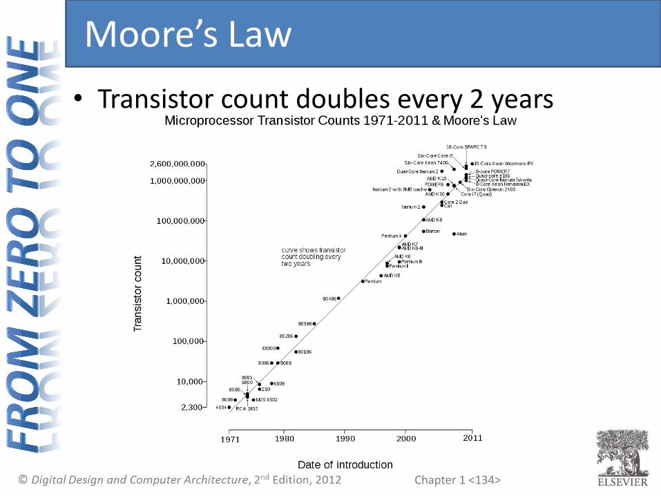
Moore’s Law
• Transistor count doubles every 2 years

Chapter 1 <135>
Moore’s Law Trends
GPUs
• “If the automobile had followed the same development cycle as the computer, a Rolls-Royce would today cost $100, get one million miles to the gallon, and explode once a year . . .”
– Robert Cringley

Chapter 1 <136>
Power Consumption
• Power = Energy consumed per unit time
• Two types of power
• Dynamic power consumption
• Static power consumption
Chapter 1 <137>
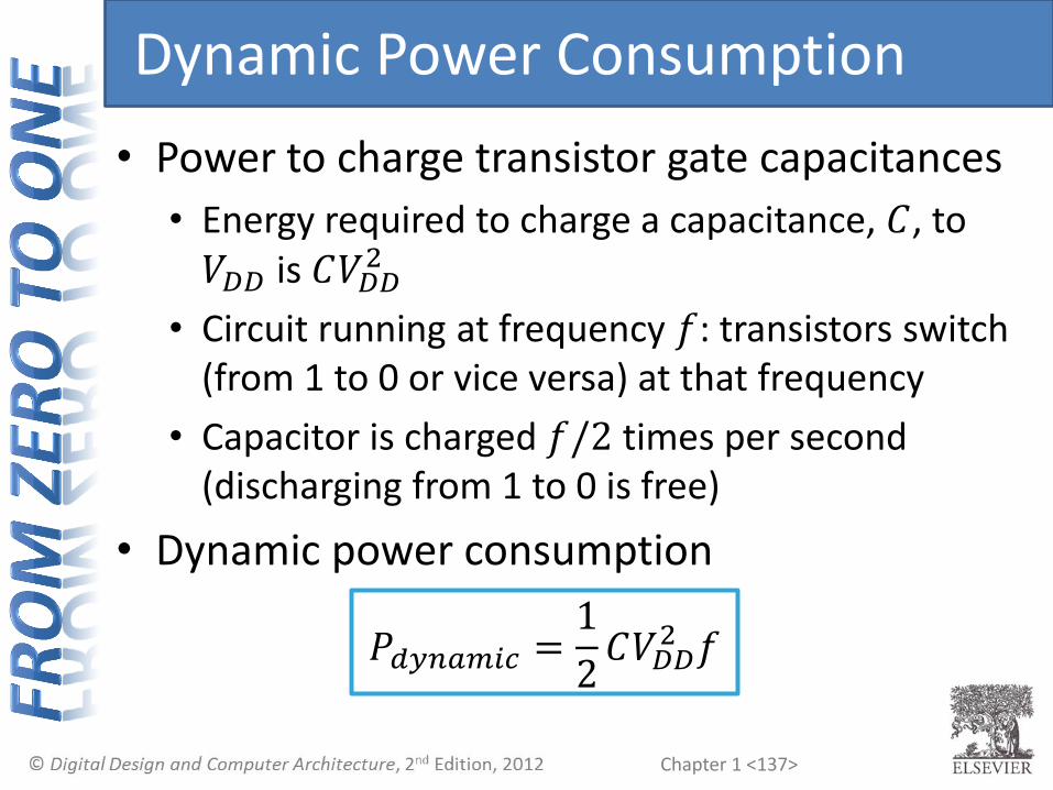
Dynamic Power Consumption
• Power to charge transistor gate capacitances
• Energy required to charge a capacitance, 𝐶, to 𝑉𝐷𝐷 is 𝐶𝑉𝐷𝐷
2
• Circuit running at frequency 𝑓: transistors switch (from 1 to 0 or vice versa) at that frequency
• Capacitor is charged 𝑓/2 times per second (discharging from 1 to 0 is free)
• Dynamic power consumption
𝑃𝑑𝑦𝑛𝑎𝑚𝑖𝑐 =
1
2𝐶𝑉𝐷𝐷
2 𝑓
Chapter 1 <138>
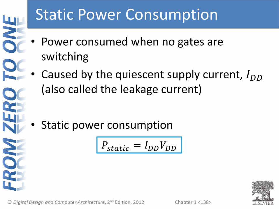
Static Power Consumption
• Power consumed when no gates are switching
• Caused by the quiescent supply current, 𝐼𝐷𝐷 (also called the leakage current)
• Static power consumption
𝑃𝑠𝑡𝑎𝑡𝑖𝑐 = 𝐼𝐷𝐷𝑉𝐷𝐷
Chapter 1 <139>
Power Consumption Example
• Estimate the power consumption of a wireless handheld computer
• 𝑉_𝐷𝐷 = 1.2 V
• 𝐶 = 20 nF
• 𝑓 = 1 GHz
• 𝐼𝐷𝐷 = 20 mA
• Total power is sum of dynamic and static

Chapter 1 <140>
Power Consumption Example
• Estimate the power consumption of a wireless handheld computer
• 𝑉_𝐷𝐷 = 1.2 V
• 𝐶 = 20 nF
• 𝑓 = 1 GHz
• 𝐼𝐷𝐷 = 20 mA
• Total power is sum of dynamic and static
𝑃 =1
2𝐶𝑉𝐷𝐷
2 𝑓 + 𝐼𝐷𝐷𝑉𝐷𝐷
=1
220 n 1.2 2 1 G
+ 20 m 1.2 = 14.4 + 0.024 W = 14.4 W