changed as described in section i, below
TRANSCRIPT
*. :) , - - - __
-f*
7 ,
%)
h
CONSUMERS PC'4ER COMPANY
Docket 50-155
Request for Change to the Technical Specifications
License DPR-6
For the reasons hereinafter set forth, it is requested that the Technical Speci-
fications centained in Provisional Operating License DPR 6, Docket 50-155, be
changed as described in Section I, below.
*
I. ' Changes
t A. Add or replace the followingi1. Table 5.1 (Page 3ha).
2. Page klb.
3 Table 1 (Page h3).
h. Table 2 (Page h3a).*
( 5 Table 8.2 (Page 91).
.
.
.
.
1
F/o//AbIT ~
- . . . .
i-
. .
!*
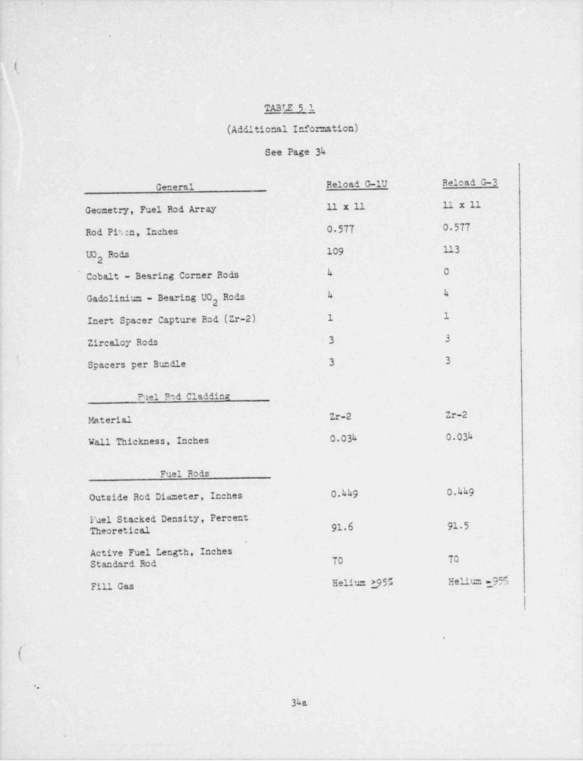
TABLE 51
(Additional Infoz=ation)
See Page 34
General Reload G-1U Relead G-3
11 x 11 11 x 11Geometry, Fuel Rod Array
Rod Pit,:n, Inches 0 577 0 577
UO Rods 109 1132
Cobalt - Bearing Corner Rods 4 0
Gadoliniu= - Bearing UO Rods k k2
Inert Spacer Capture Rod (Zr-2) 1 1
Zircaloy Rods 3 3
.,
Spacers per Bundle 3 3
Ptel Rod Cladding
Material- Zr-2 Zr-2
Wall Thickness, Inches 0.03h 0.03h
Fuel Rods
Outside Rod Diaseter, Inches 0.hh9 0.hh9
Fuel Stacked Density, PercentTheoretical 91.6 91.5
,
Active Fuel Length, Inches
Standard Rod 70 70
Fill Gas Heliu 2955 Helium 955'
l:
f.
(,
..
3ha
.
_. .

.
.
k,
FUEL BUNELE SCHEM.ATIC
G-3 RELOAD FUEL
(TO BE SUPPLIED)
.
&
9
(
,h1b
'
.
r 6- A s
,
t
.
' ',
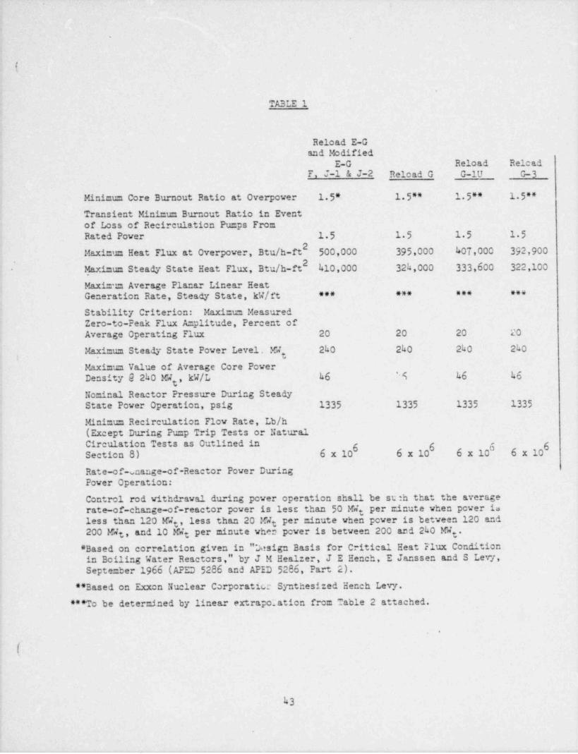
TABLE 1
Reload E-Gand Modified
E-G Reload RelcadF, J-l & J-2 Reload G G-1U G-3
Minimum Core Burnout Ratio at Overpower 1 5* 1 5** 1 5** 1 5**Transient Minimum Burnout Ratio in Eventof Loss of Recirculation Pumps FromRated Power 15 15 15 1.5
Maximum Heat Flux at Overpower, Btu /h-ft 500,000 395,000 407,000 392,900
- ' Maximum Steady State Heat Flux, Btu /h-ft 410,000 324,000 333,600 322,100
Maxim:m Average Planar Linear HeatGeneration Rate, Steady State, kW/ft - *** *** *** ***
Stability Criterion: Maximum MeasuredZero-to-Peak Flux A=plitude, Percent ofAverage Operating Flux 20 20 20 20
Mayimum Steady State Power Level. My 2h0 240 240 2h0
Maximum Value of Average Core PowerDensity 9 240 MR , kW/L h6 4 h6 h6
g
Nominal Reactor Pressure During SteadyState Power Operation, psig 1335 1335 1335 1335
Minimum Recirculation Flow Rate, Lb/h-(Except During Pump Trip Tests or NaturalCirculation Tests as Outlined inSection 8) 6 x 10' 6 x 10' 6 x 10 6 x 10'
-
D
Rate-of unange-of-Reactor Power DuringPower Operation:
Control rod withdrawal during power operation shall be stah that the averagerate-of-change-of-reactor power is less than 50 M4t per r.inute when power isless than 120 MW , less than 20 Wt per minute when power is between 120 ande200'MW , and 10 MW per minute when power is between 200 and 2h0 MW . |
t g
* Based on correlation given in "*Jesign Basis for Critical Heat Flux Conditionin Boiling Water Reactors," by J M Healzer, J E Hench, E Janssen and S Levy,September 1966 (APED 5286 and APED 5286, Part 2).
** Based on Exxon Nuclear Corporatice Synthesized Hench Levy.
***To be determined by linear extrapo:ation from Table 2 attached.1
- (L,
I
h3
4
e
.
* . -. . _. . . . , - 7 _ ,, , --- -- - - , - - , -- -.,, , ---, . ~ . - .
|.-
1
I
*\
k !
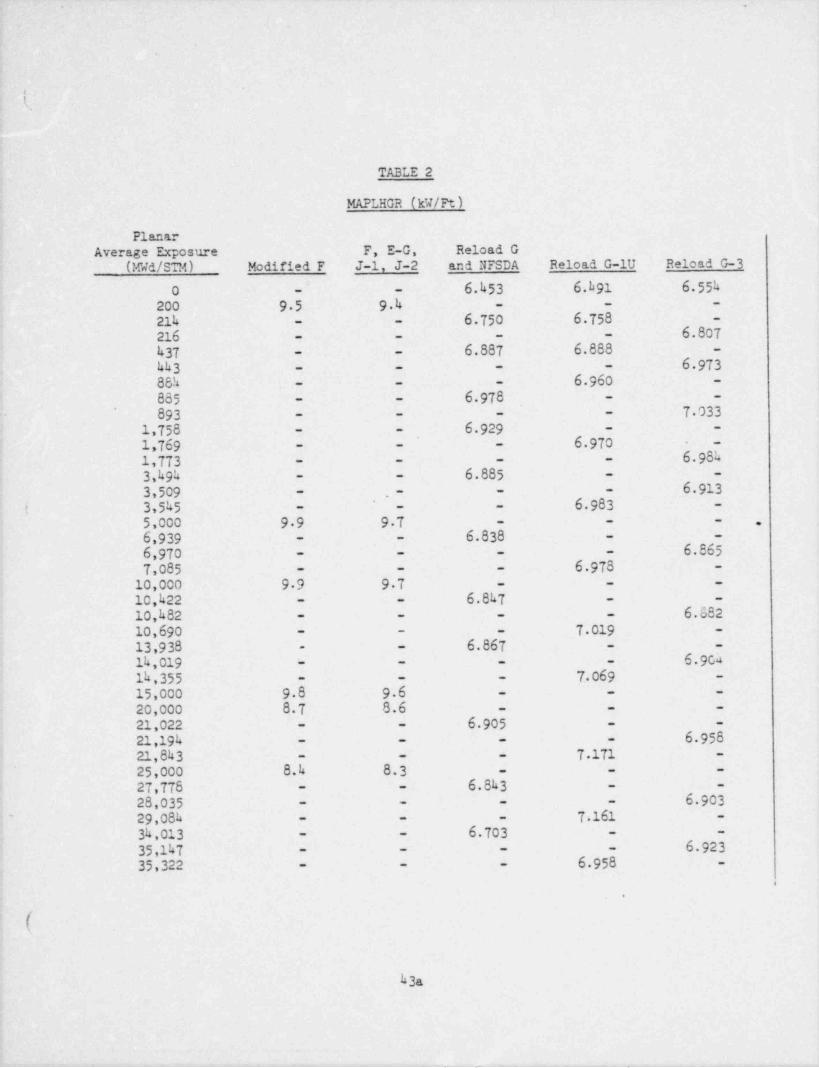
TABLE 2
MAPLHGR (kW/Ft)
PlanarAverage Exposure F, E-G, Reload G
UGd/STM) Modified F J-1, J-2 and NFSDA Reload G-1U Reload G-3
6.h53 6.h91 6.55h0 - -
200 95 9.4 - - -
21h 6.750 6.758 -- -
6.807216 - - - -
437 6.887 6.888 -- -
6 973hh3 - - - -
- - - 6.96088h -
6.978~
885 - -- -
7 033893 - - - -
6.9291,758 - -- -
- -- - 6 9701,769 -
6.9841,773- - - - -4
6.8853,494 - -- -
6.9133,509 - -.--
6.983( 3,5k5 -- - -
5,000 99 97 - - - . ,
6.8386,939 - -- -
6.8656,970 - - - -
6 9787,085 -- - -
10,000 99 97 - - -
6.8k710,422 - -- -
6.88210,h82 - - - -
10,690 - - - 7 019 -
6.86713,938 - -- -
6 9ch14,019 - - - -
- - - 7.069 -1k,35515,000 9.8 96 - - -
20,000 8.7 8.6 - - -
6.90521,022 - -- -
6 95821,194 - - - -
7 17121,843 -- - -
25,000 8.4 8.3 - - -
6.8k3 - -27,778 - -
6.90328,035 - - - -
7 161- 29,08k -- - -
- - 6.70334,013 - -
6.92335,147 - - - -
6.95835,322 -- - -
. ,
!.
|
( I
h3a
|
||
_ _ -._ _ _
_
,'
.
.
i
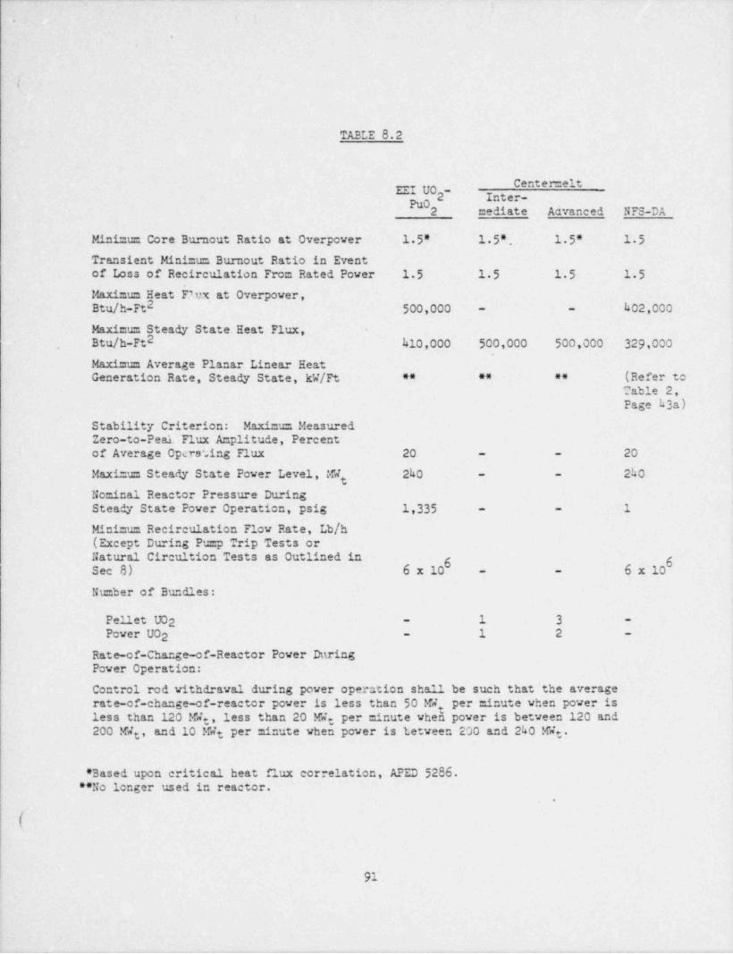
TABLE 8.2
en emeltEEI UO -" *#~
Pu02 mediate Advanced NFS-DA
Minimum Core Burnout Ratio at Overpower - 1 5"' l.5*. 1 5" 15Transient Minimus Burnout Ratio in Eventof Loss of Recirculation From Rated Power 15 15 15 15Maximum Heat F.'.ux at Overpower,Btu /h-Ft2 h02,000500,000 - -
Maximus Steady State Heat Flux,
, Btu /h-Ft2 h10,000 500,000 500,000 329,000
Maimum Average Planar Linear Heat(Refer toGeneration Rate, Steady State, W/Ft ** ** **
Table 2,Page h3a)
Stability Criterion: Maximus MeasuredZero-to-Peal. Flux Amplitude, Percent
- - 20of Average Opcrating Flux 20
t- 2h0Maximum Steady State Power Level, W 2h0 -
Nominal Reactor Pressure DuringSteady State Power Operation, psig 1,335 1- -
Minimum Recirculation Flow Rate, Lb/h(Except During Pump Trip Tests orNatural Circultion Tests as Outlined in
6 6Sec 8) 6 x 10 6 x 10- -
Number of Bundles:
1 3Pellet U02 --
Power UO2 - 1 2 -
Rate-of-Change-of-Reactor Power DttringPower Operation:
Control rod withdrawal during power operntion shall be such that the averagerate-of-change-of-reactor power is less than 50 W. per minute when power is !
less than 120 We, less than 20 W: per minute when power is between 120 and200 W , and 10 Wt per minute when power is tetween 200 and 240 W .e t
|
* Based upon critical heat flux correlation, APED 5286. !|**No longer used in reactor.
-
91
.
.
\
kS
,
1
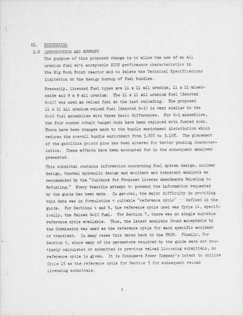
II. DISCUSSION
1.0 INTRODUCTION AND SUldARY
The purpose of this proposed change is to anov the use of an alluranium fuel with acceptable ECCS performance characteristics inthe Big Rock Point reactor and to delete the Technical Specificationsli=itation on the design burnup of fuel bundles.
Presently, licensed fuel types are 11 x 11 all uranium,11 x 11 mixed-oxide and 9 x 9 an uranium. The n x n all uranium fuel (denoted
]G-lU) was used as reload fuel at the last reloading. The proposed11 x 11 all-uranium reload fuel (denoted G-3) is very similar to theG-lU fuel assemblies with three basic differences. For G-3 assemblies,the four corner cobalt target rods have been replaced with fueled rods.
'
There have been changes made to the bundle enrich =ent distribution whichreduces the overan bundle enrichment from 3.885 to 314%. The placement
of the gadolinia poison pins has been altered for better peaking character-istics. These effects have been accounted for in the subsequent analyses
(
presented.'
This submittal contains information concerning fuel system design, nucleardesign, ther=al hydraulic design and accident and transient analysis asreco== ended by the " Guidance for Proposed License Amendments Relating to
Refueling." Every feasible attempt to present the infor=ation requestedby the guide has been made. In geraral, the major difficulty in providingthis data was in for=ulating a suitable " reference cycle" -- defined in theguide. For Sections k and 6, the reference cycle used was Cycle ik, specif-
,
ically, the Reload G-1U' fuel. For Section T, there was no single suitablereference cycle available. Thus, the latest analysis found acceptable bythe Co==ission was used as the reference cycle for each specific accidentor transient. In many cases this dated back to the FHSR. Finan y, forSection 5, since many of the parameters required by the guide were not rou-~
tinely calculated or submitted in previous reload licensing sub=ittals, noreference cycle is given. It is Consumers Power Company's intent to utilizeCycle 15 as the reference cycle for Section 5 for subsequent, reloadlicensing sub=ittals.
2 ,
i
I
.
%
g v- ,wy
!
t_
I
( .
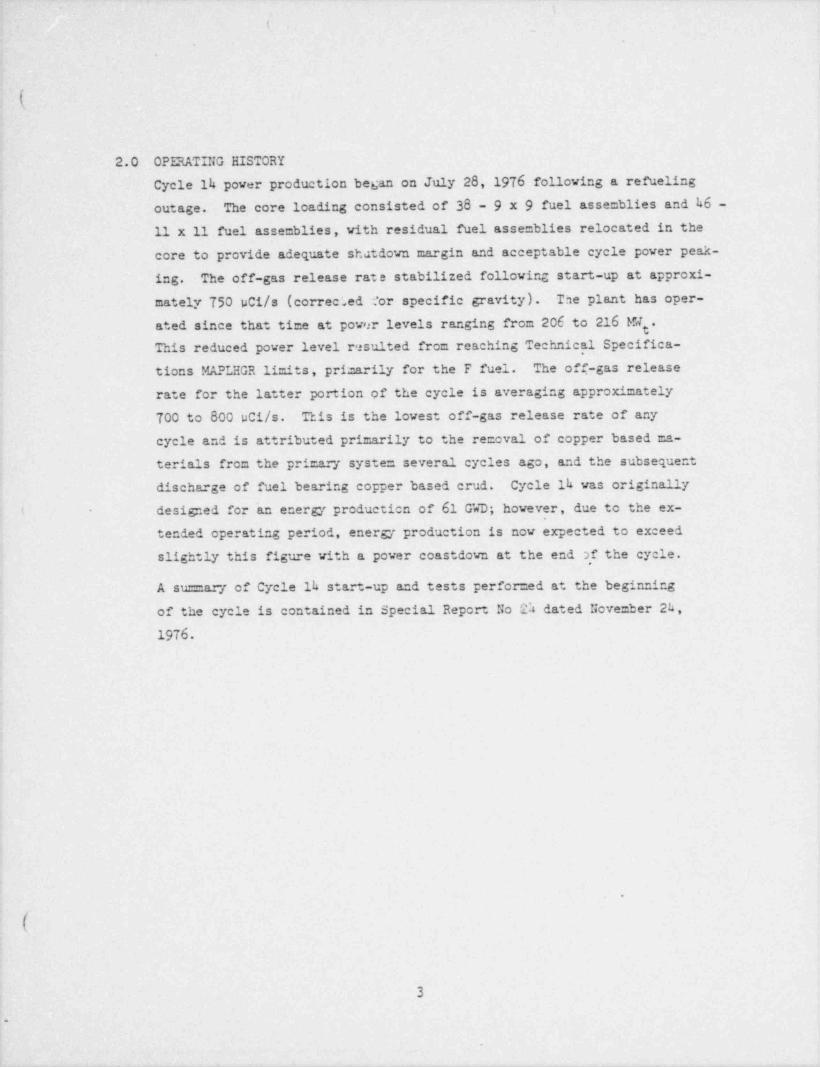
2.0 ' OPERATING HISTORY
Cycle 14 power production began on July 28, 1976 following a refuelingoutage. The core loading consisted of 38 - 9 x 9 fuel assemblies and 46 -11 x 11 fuel assemblies, with residual fuel assemblies relocated in thecore to provide adequate shatdown margin and acceptable cycle power peak-ing. The off-gas release rate stabilized following start-up at approxi-mately 750 uCi/s (corree;ed : tor specific gravity). Tae plant has oper-ated since that time at power levels ranging from 206 to 216 l& .This reduced power level resulted from reaching Technical Specifica-tions MAPLHGR li=its, pri=arily for the F fuel. The off-gas releaserate for the latter portion of the cycle is averaging approximately700 to 800 uCi/s. This is the lowest off-gas release rate of any
cycle and is attributed primarily to the re= oval of copper based ma-terials from the pr %7 system several cycles ago, and the subsequentdischarge of fuel bearing copper based crud. Cycle lh was originally
. designed for 'an energy production of 61 G'4D; however, due to the ex-1-
tended operating period, energy production is now expected to exceedslightly this figure with a power coastdown at the end af the cycle.
A su==ary of Cycle lh start-up and tests performed at the beginningof the cycle is contained in Special Report No D dated Nove=ber 24,
1976.
.
3
.
>
-- -c.
4
i . |
ll
(
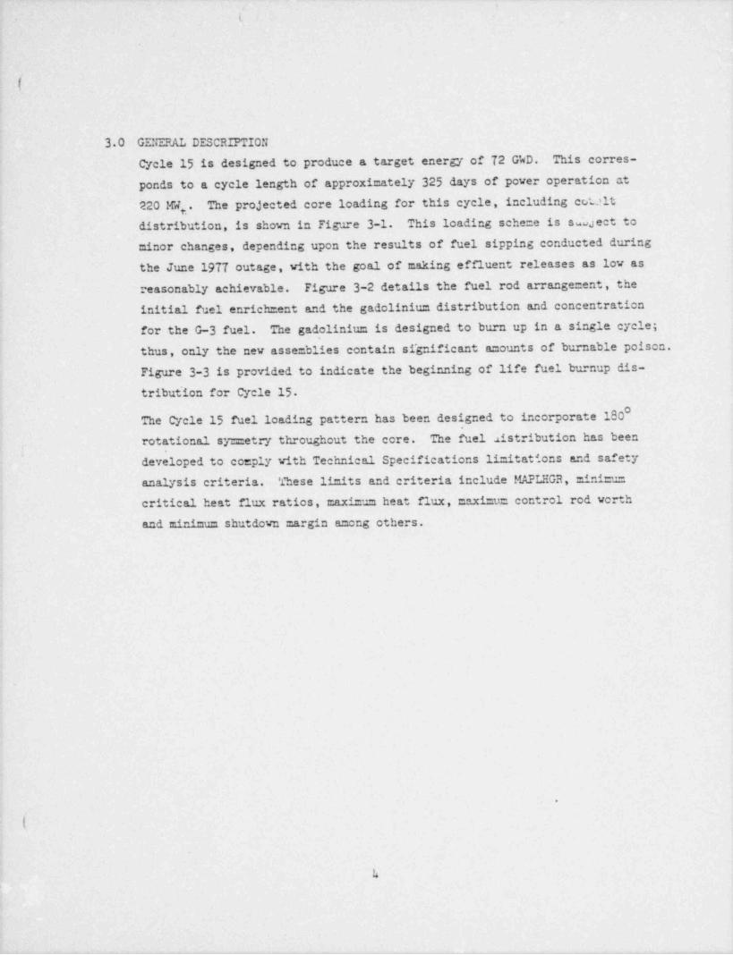
30 GENERAL DESCRIPTION
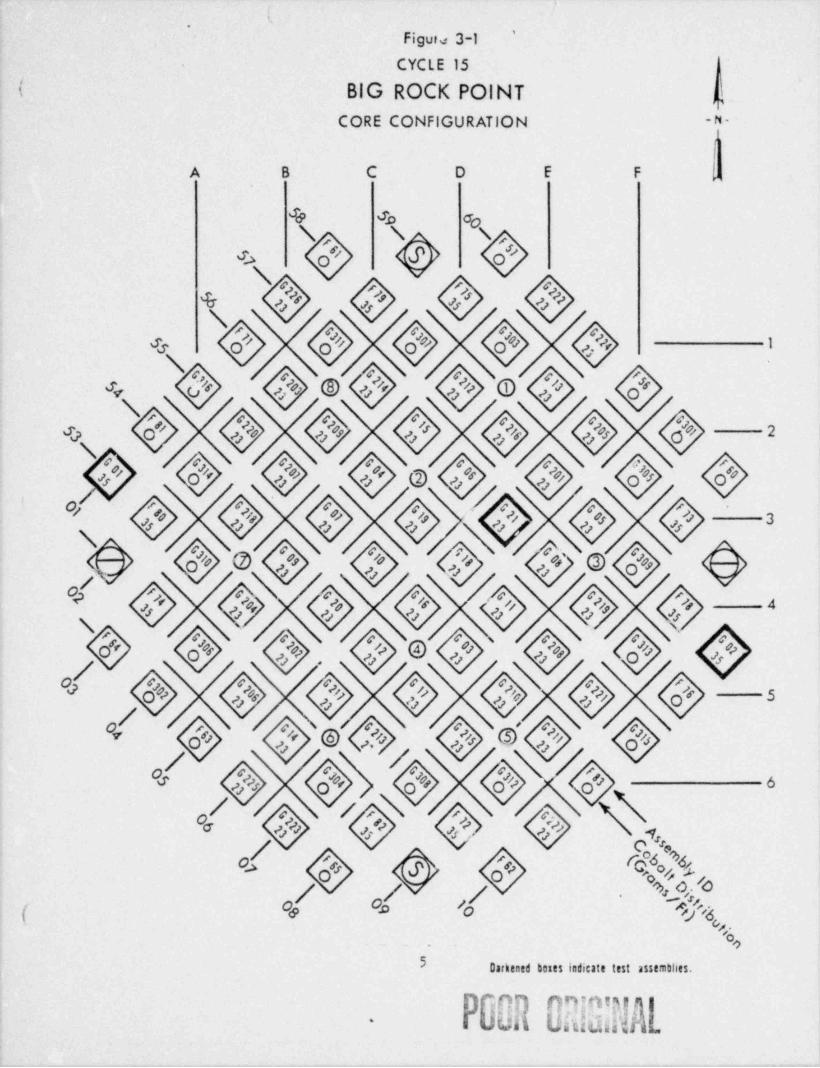
Cycle 15 is designed to produce a target energy of 72 G'dD. This corres-
ponds to a cycle length of approximately 325 days of power operation at
220 !G ,. The pro,1ected core loading for this cycle, including cotaltdistribution, is shown in Figure 3-1. This loading sche =e is aduject to
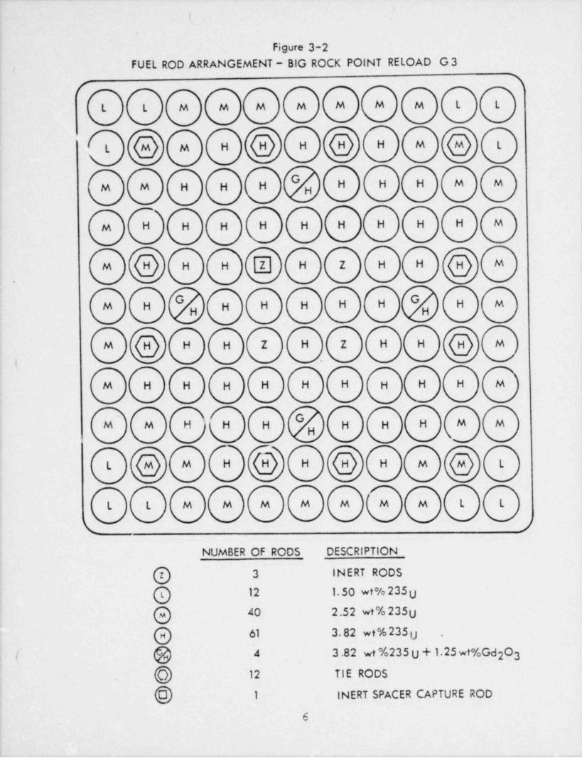
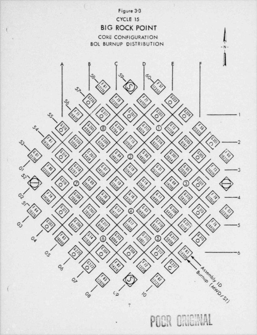
minor changes, depending upon the results of fuel sipping conducted duringthe June 1977 outage, with the goal of making effluent releases as lov asreasonably achievable. Figure 3-2 details the fuel rod arrange =ent, theinitial fuel enrichment and the gadolinium distribution and concentrationfor the G-3 fuel. The gadolinium is designed to burn up in a single cycle;thus, only the new assemblies contain si'gnificant amounts of burnable poisen.Figure 3-3 is provided to indicate the beginning of life fuel burnup dis-tribut' ion for Cycle 15
The Cycle 15 fuel loading pattern has been designed to incorporate 180rotational sy=cetry throughout the core. The fuel 21stribution has been
,
developed to comply with Technical Specifications limitations and safetyanalysis criteria. These limits and criteria include MAPLHGR, =ini==critical heat flux ratios, maxi =um heat flux, maximu= control rod worthand mir Mus shutdown margin among others.
.
(e
.
ii
1
_ _
_ _ _ _ _ _ _
''
Figure 3-1
CYCLE 15 (( BIG ROCK POINT d
CORE CONFIGURATION - -
A B C D E F ,
4 Jo do
#>
s'4 4 4 4+%#%4% ''
s 4 4e4 40% 4s*e% %
%@%(44 4444444
#%%'
4 + 4 4 > 4 +'% o #n # o'
>
*D'e %% e %#e <
'
4 4.Oe4'O 4 4z
+'e 4 4 4&s+ + e
>
ses,se
's*4 0 4+X+Nses%
-
+
#.O,
< , . + .
.
5 Dukened buts indicate test assemthes.
P00R BRIB R.
-
a
. .
1
:
'
Figure 3-2
FUEL ROD ARRANGEMENT- BIG ROCK POINT RELOAD G 3,,
(L L M M M M M M M L L
hH hH hLhM MHL
GM M H H H " " "
H
M H H H H H H H H H M
hH H [ H Z H H MM
G GM H H H H H H H MH H
hH H Z H Z H H MM.
i .
M H H H H H H H H H M
M M H H H H H H M MH
hH hHhM H M LL
L L M M M M M M M L L
t >NUMBER OF RODS DESCRIPTION
@ 3 INERT RODS
@ 12 1.50 wt% 235U40 2.52 wt% 235U@61 3.82 wt%235g@ .
( @ 4 3.82 wt %235 U + 1.25 wt%Gd O32
h 12 TIE RODS.
h 1 INERT SPACER CAPTURE ROD
6
. . _ . . _. .- .. .
('
,
Figure 3-3,
CYCLE 15
| BIG ROCK POINT(CORE CONFIGURATION.
|BOL BURNUP DISTRIBUTION _g,
'
.
A B C D li :-
'
& 30 0
4 's e'
'
t4444 |+44444 |'s
s 4 4*4 See 4s o 4 4 4 4 4 4.4 4 4 See 4 4 @,
(''4+4e4 4 4See O444444>/4444440 4
/4&#e'4e44'4 44 4 e4
A>4 4 -44.
44:
/ 4 4e./ 4 4 4 4 e\ -
/ 4444./ q /q /q %.
./ \< c ,
&J
P90RBRiBIE-
-- -_.
_ _ .
'
( 1
|'
.
I{.
4.0 FUEL SYSTEM DESIGN
The G-3 reload fuel design for Cycle 15 has mechanical, thermal hydraulicand neutronic perfor=ance characteristics similar to the G-1U reload fueldesign for Cycle ik, the reference cycle. Both G-1U and G-3 fuels employ ,
an 11 x 11 red matrix with four inert rods; however, G-1U fuel design incor-porated four corner. cobalt rods necessitating a slightly higher enrichmentthan G-3 fuel. A complete description of the mechanical, thermal hydraulicand neutronic characteristics of the G-1U fuel was presented in our letterdated Octobar 13, 1975
~ - ~ ~ ~
f k.1 Fuel Design
As discussed previously, the major fuel design change for Reload G-3fuel when compared to Reload G-1U fuel is the elimination of the four
35cobalt target rods and the reduction of the overall U er:richment.
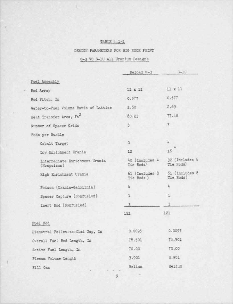
Table k.1-3 lists the design para =eters for both the G-3 proposed
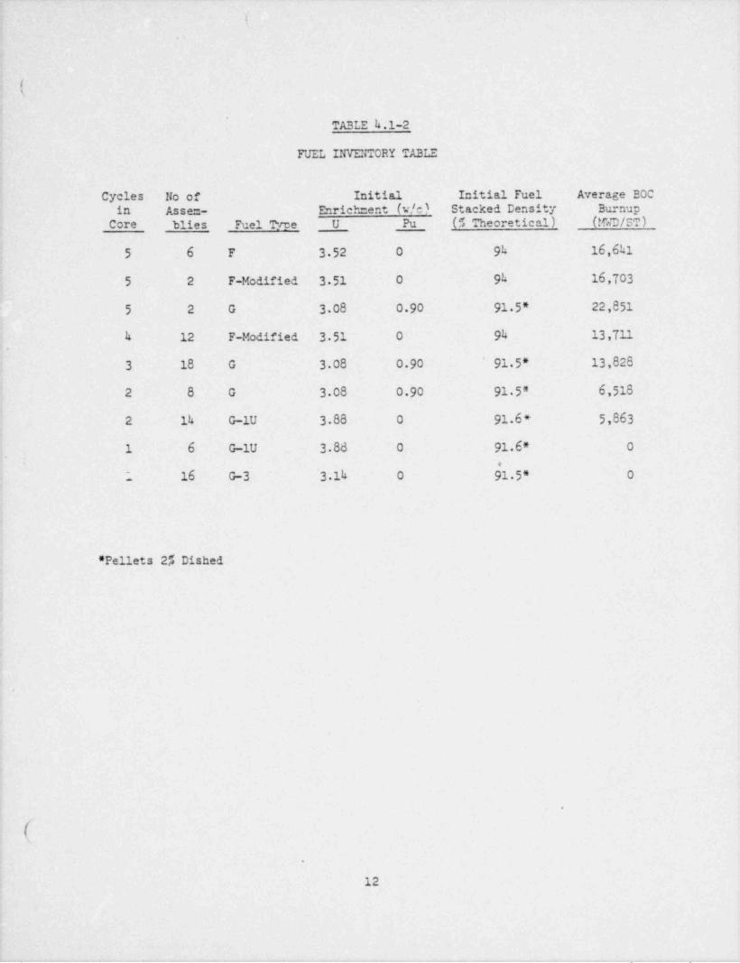
fuel and the G-1U reference fuel. Table k.1-2 delineates the fuel'
in'ientory at BOC for Cycle 15 It consists of the fuel type, nu=ber
of assemblies, number of cycles in core, and initial BOC enrichment,density and average burnup. The G-3 fuel is desigued to be free-standing throughout its life in core, which is consistent with previousI
G reload fuels and, like other G fuels, G-3 was initially filled atnominal atmospheric pressure.
4
:
!
l
.
9
(
8
.
e - a w a - -- , , ,,,
Ii,.
(,
*
TABLE h.1-1
DESIGN PARAMETERS FOR BIG ROCK POINT
G-3 VS G-1U All Uraniun Designs
Reload G-3 G-1U
Fuel Asse=bly
Rod Array 11 x 11 11 x 11*
Rod Pitch, In 0 577 0.577
Water-to-Fuel Volume Ratio of Lattice 2.60 2.69.
2Hest Transfer Area' Ft 80.23 77.48,
Nu=ber of Spacer Grids 3 3'
Rods per Buadle
Cobalt Target 0 h.
Lov Enrichment Urania 12 16
Inte mediate Enrichment Urania h0 (Includes h 32 (Includes k(Nonpoison) Tie Rods) Tie Rods)'
High Enrichment Urania 61 (Includes 8 61 (Includes 8Tie Rods) Tie Rods)
Poison (Urania-Gadolinia) h h
Spacer Capture-(Nonfueled) 1 1
Inert Rod (Nonfueled) 3 3
121 121
Fuel Rod
Dia=etral Pellet-to-Clad Gap, In 0.0095 0.0095
Overall Fuel Rod Length, In 78.501 -78.501
,
Active Fuel Length, In 70.00 70.00
.
Plenum volu=e Length 3.901 3 9dl
Fill Gas Helium Helium^
'
1<
- . .
9-
|
(
-(
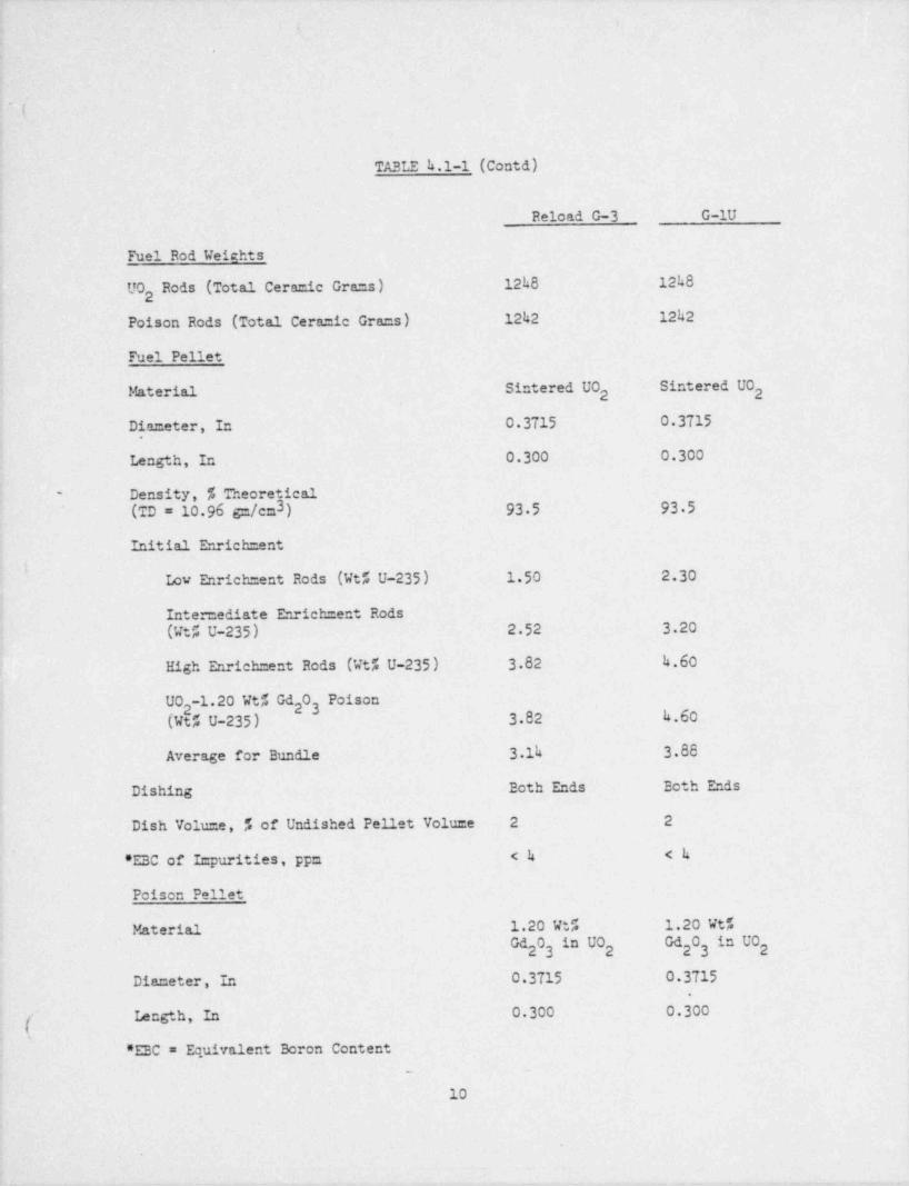
TABLE k.1-1 (Contd)J
Reload G-3 G-lU
Fuel Rod Weights
UO Rods (Total Ceramic Gra=s) 12k8 12h82
Poison Rods (Total Ceramic Gra=s) 1242 12h2
Fuel Pellet
Material Sintered UO Sintered UO2 2
Diameter, In 0 3715 0.3715
Length, In 0.300 0.300
Density, % Theoretical'
(TD = 10.96 sn/c=3) 93.5 93.5
Initial Enrich =ent
- iLow Enrich =ent Rods (Wt% U-235) 1.50 2.30
Intermediate Enrich =ent Rods(Wt% U-235) 2 52 3 20
High Enrich =ent Rods (Wt% U-235) 3.82 4.60'
UO -1.20 Wt% Gd 0 18 "2 23
(Wt5 U-235) 3.82 h.60
Average for Bundle 3.1h 3.88
Dishing Both Ends Ecth Ends
Dish Volume, 5 of Undished Pellet Volu=e 2 2
*EBC of I= purities, pp= <h <h
Poison Pellet
Material 1.20 Wt% 1.20 Vt%Gd 0 " 0 d0 n 023 2 23 2
Diameter, In 0.3715 0 3715.
~
Length, In 0.300 0.300
*EEC = Equivalent Boron Content-
10
i
- ._
. _ . , |
( I
~ (
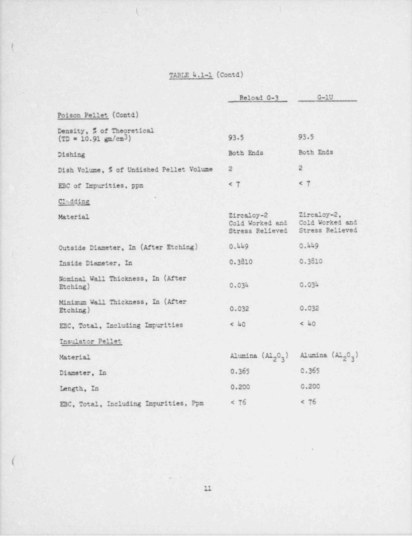
TABLE h.1-1 (Contd)
.
Reload G-3 G-lU
Poison Pellet (Contd)
Density, % of Theoretical(TD = 10 91 gm/cm3) 93.5 93 5
Dishing Both Ends Both Ends
Dish Volume, % of Undished Pellet Volume 2 2
EBC of Impurities, pp= <T <T*
Cisdd h
Material Zircaloy-2 Zircaloy-2,
Cold Worked and Cold Worked andStress Relieved Stress Relieved
- Outside Diameter, In (After Etching) 0.hh9 0.kh9t
Inside Diameter, In 0 3810 0.3810
Nominal Wall Thickness, In (AfterEtching) 0.03h 0.03h
Minimm Wall Thickness, In (AfterEtching) 0.032 0.032
EBC, Total, Including Impurities < 40 < h0
Insulator Pellet
Material Alumina (A1 0 "" 023 23-
Diameter, In 0.365 0.365
Iength, In 0.200 0.200
EBC, Total, Including Impurities, Ppm < 76 < 76.
H
$
.
.
.
-.
\
t\
TABLE h.1-2
FUEL INVENTORY TABLE
Cycles No of Initial Initial Fuel Average BOC'in Assem- Enrichment (w/c) Stacked Density Burnup
~ Core blies Fuel Tyre U Pu ( #, Theoretical) (!GD/ST)
5 6 F 3.52 0 94 16,641
5 2 F-Modified 3 51 0 9h 16,703
~
5 2 G 3 08 0 90 91.5" 22,851
h 12 F-Modified 3.51 0 94 13,711.
3 18 G 3.08 0.90 91 5* 13,828
2 8 G 3 08 0.90 91 5* '6,518
2 14 G-1U 3.88 0 91.6 * 5,863i
1 6 G-1U 3.88 0 91.6* 0, .
~. 16 G-3 '3 1h 0 91.5* 0
' Pellets 2" Dished,
i
s
e
6
..
(.
12
. . _ . , _ _ _ . u ._. - . _

- .
t is
- k'
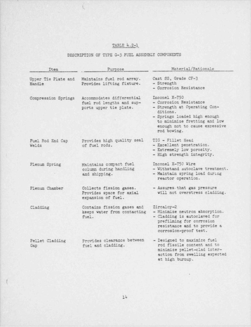
h.2 Mechanical Design
The mechanical design of the Reload G-3 fuel is consistent with thereference G-lU fuel with the exception of the upper tie plate. Thisplate was modified slightly in the Reload G-3 design to provide stan-dard fuel rod location holes in each corner of the plate replacingthe locking slots utilized by the cobalt target rods. By lettersdated June 16, 1972 and October 13, 1975, mechanical design analysesfor Reload G and Reload G-1U fuels were submitted; these analyses
are applicable for Reload G-3 fuel. Table h.2-1 describes the G-3fuel assembly components, their purpose and cosposition.
,
.
S
O
e
a
9
9
4
5
(
''
13.
4
,- -, - -. . - . . -
e.
'
1
1
TABLE k.2-1
DESCRIPTION OF TYPE G-3 FUEL ASSEMBLY COMPONEFIS
Item Purpose Material / Rationale,
Upper Tie Plate and Maintains fuel rod array. Cast SS, Grade CF-3Handle Provides lifting fixture. - Strength
- Corrosion Resistance
Compression Springs Accommodates differential Inconel X-750fuel rod lengths and sup- - Corrosion Resistanceports upper tie plate. - Strength at Operating Con-
ditions.
'
- Springs loaded high enoughto minimize fretting and lovenough not to cause excessiverod bowing.
Fuel Rod End Cap Provides high quality seal TIG - Fillet HeadWelds of fuel rods. - Excellent penetration.
- Extremely low porosity'.
i - High strength integrity.
Plenum Spring Maintains co= pact fuel Inconel X-750 Wirecolu=n during handling - Withstand autoclave treatment.
* and shipping. - Maintain spring load duringreactor operation.
Plenus Chamber Collects fission gases. - Assures.that gas pressureProvides space for axial vill not overstress cladding.
expansion of fuel.
Cladding Contains fission gases and Zircaloy-2keeps water from contacting - Minimize neutron absorption.
fuel. - Cladding is autoclaved forprefilming for corrosionresistance and to provide acorrosion-proof test.
Pellet Cladding Provides clearance between - Designed to maxinite fuel
Gap- fuel and cladding. rod fissile content and tominimize pellet-clad inter--action from swelling expectedat high burnup.
.
lh

%f'(
.
.
(.
TABLE h.2-1 (Contd)
Item Purpose Material / Rationale
Insulator Pellet Reduces pellet-nonpellet Al 023interface temperature. - Maintains te=perature below
those causing excessive stresslevels and below those of con-cern with metal-fuel reaction.
- Controls hydride preceiptation.
Atmosphere Heat transfer medium be- Heliumtween pellet and clad. - Good heat transfer character-
istics.- Provides an easy and reliable-
leak detection monitoringmeans.
Spacers Maintains correct rod-to- Zircaloy-b Fra=e, Inconel 718rod spacing. Springs
- - Corrosion minimized.- Mechanical stability,
i - Spring loads on cladding =ustbe sufficient to minimizelateral and rotational move-ment of fuel rod but cust notcause excessive cladding orspring stress.
- Spacer must not cause exces-sive coolant flow resistance.
Inert Rods Displaces the highest peak Zircalcy-2 Cladding End Caps ..clad temperature rods under FillerLOCA conditions and provide - Corrosion resistance,
a radiation sink. - Lov absorption crosssection.
Botton Tie Plate Paintains fuel rod array Cast SS, Grade CF-3and distributes coolant - Strength.to fuel rods. - Corrosion resistance.
Spacer Capture Rod Maintains correct longi- - Continuous clad andtudinal position of formed Zircaloy sheetspacers, stock connectors.
Tie Rod Provides structural skeleton Zr-2 clad fuel rods with endof assembly by securing the fittings for attach =ent to |
upper and lover tie plates. tie plates. '
,
,
k
15
.

. . .. . -
i(. .
I\,
'
k.3 Thermal Design
The design basis for the thermal performanc? of Reload G-3 fuel is identi-cal to that described in our submittals dated June 16, 1972 and October 13,1975 for Reload G and G-1U, respectively.
~
,
h.4 Chenical Design
The adequacy of materials selected for the chemical fuel design has beendemonstrated through the excellent performance of Exxon Nuclear Fuels todate. Past irradiation tests for assemblies similar to G-3 have producedno fuel failures or degradation due to incompatibility with the reactor
,
water chemistry. Results of the post-irrt.diation examinations of fuelassemblies, including those of the G design, are contained in Special*
.
Report No 2k dated November 2k, 1976.
"
:
i
9
--
5
16
.
,-,=w- , , - .--w-,, s ,, s,m- . . .-c-. - y
i.t
.
.
1
.{ 1
.
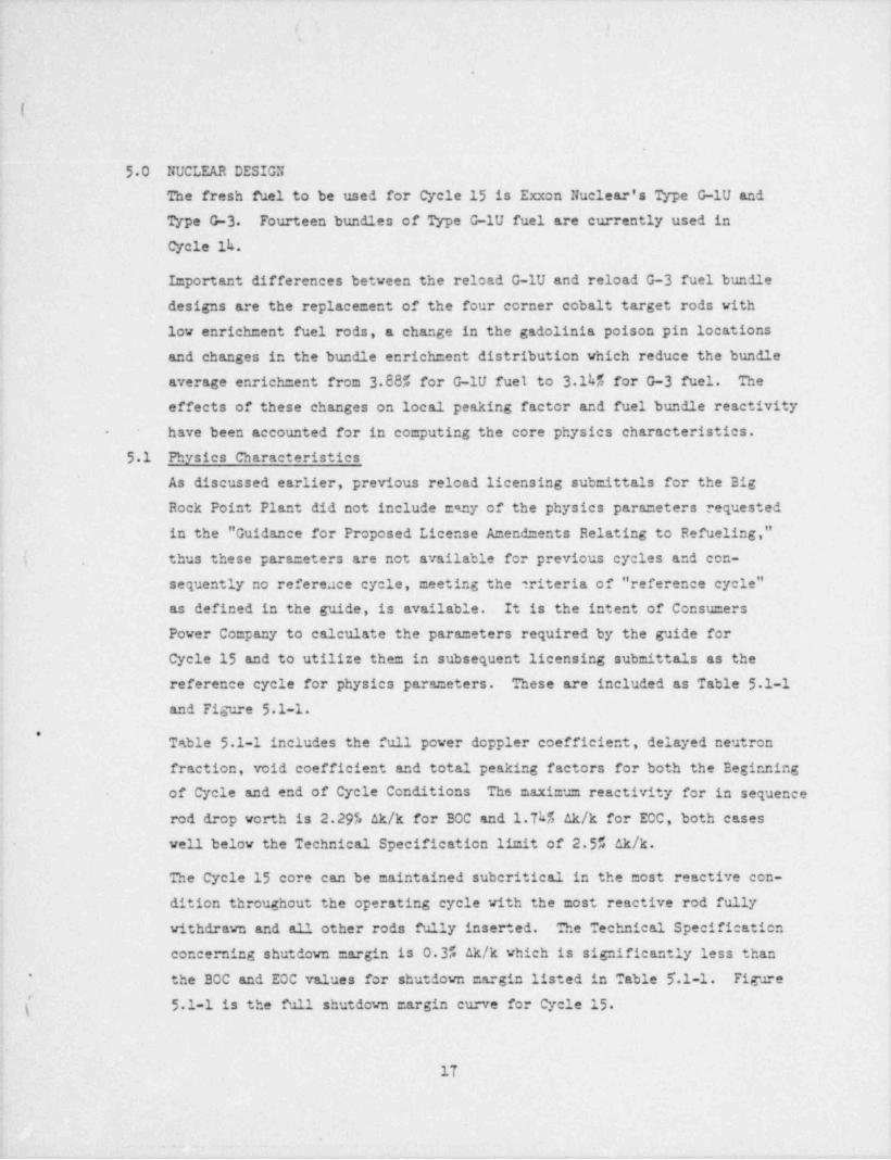
50 NUCLEAR DESIGNThe fresh fuel to be used for Cycle 15 is Exxon Nuclear's Type G-1U and
Type G-3 Fourteen bundles of Type G-1U fuel are currently used in
Cycle 1k.
Important differences between the reload G-1U and reload G-3 fuel bundledesigns are the replacement of the four corner cobalt target rods with
lov enrichment fuel rods, a change in the gadolinia poison pin locationsand changes' in the bundle enrich =ent distribution which reduce the bundleaverage enrich =ent from 3.88% for G-1U fuel to 3.1h% for G-3 fuel. Theeffects of these changes on local peaking factor and fuel bundle reactivity
have been accounted for in ce=puting the core physics characteristics.-
5.1 Physics Characteristics
As discussed earlier, previous reload licensing submittals for the Big
Rock Point Plant did not include esny of the physics para =eters requested
in the " Guidance for Proposed License Amendments Relating to Refueling,"
( thus these para =eters are not available for previous cycles and con-,
sequently no refereace cycle, meeting the triteria of " reference cycle"as defined in the guide, is available. It is the intent of Consumers
Power Co=pany to calculate the para =eters required by the guide for
Cycle 15 and to utilize them-in subsequent licensing submittals as the
reference cycle for physics parameters. These are included as Table 5 1-1
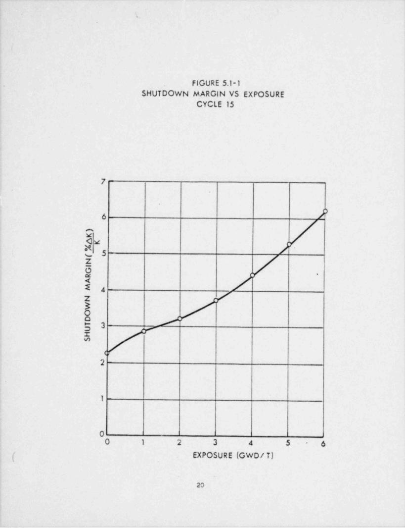
and Figure 5.1-1.
*Table 5.1-1 includes the full power doppler coefficient, delayed neutron
fraction, void coefficient and total peaking factors for both the Beginning
of Cycle and end of Cycle Conditions The maximum reactivity for in sequencerod drop vorth is 2.295 ak/k for BOC and 1.Th% Ak/k for ECC, both caseswell below the Technical Specification limit of 2.55 ak/k.
The Cycle 15 core can be maintained suberitical in the most reactive con-
dition throughout the operating cycle with the most reactive rod fully
withdrawn and all other rods fully inserted. The Technical Specificatica
concerning shutdown =argin is 0.3% Ak/k which is significantly less thanthe BOC and EOC values for shutdown cargin listed in Table 5.1-1. Figure'
( 5 1-1 is the full shutdown =argin curve for Cycle 15.
17
is
.
I
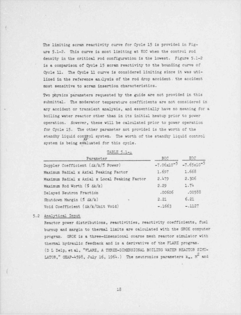
The limiting scram reactivity curve for Cycle 15 is provided in Fig-
ure 5.1-2. This curve is most limiting at EOC vhen the control rod
density in the critical rod configuration is the lowest. Figure 5 1-2
is a comparison of cycle 15 scram reactivity to the bounding curve of*
Cycle 11. The Cycle 11 curve is considered limiting since it was uti-lized in the reference analysis of the rod drop accident . the accidentmost sensitive to scram insertion characteristics.
bTwo I ysics'pa'rameters requested by the guide are not provided in thissubmittal. The moderator temperature coefficients are not considered in
acy accident or transient analysis, and essentially have no meaning for a-
boiling water reactor other than in its initial heatup prior to power
operation. However, these vill be calculated prior to power operation
for Cycle 15 The other parameter not provided is the worth of the
standby liquid control system. The worth of the standby liquid controlfr
system is being evaluated for this cycle.
' '
TABLE 5.1-1Parameter BOC EOC
Doppler Coefficient (Ak/k/% Pover) -7 06x10-5 -7.65x10⁻⁵Maximu= Radial x Axial Peaking Factor 1.697 1.668
Maximum Radial x Axial x Local Peaking Factor 2.hT9 2 306
Maximum Rod Worth (5 Ak/k) 2.29 1.Th
Delayed Neutron Fractio'n .00606 .00588
2.21 6.21Shutdown Margin (% ak/h) -
Void Coefficient (ak/k/ Unit Void) .1663 .1127
52 Analytical Intut
Reactor power distributions, reactivities, reactivity coefficients, fuelburnup and margin to ther=al limits are calculated with the GROK computerprogram. GROK is a three-dimensional-coarse mesh reactor si=ulator withther=al hydraulic feedback and is a derivative of the FLARE program.(D L Delp, et al, " FLARE, A TERIE-DIMENSIONAL BOILING WATER REACTOR SIMU-
LATOR," GEAP h598, July 16, 196h.) The neutronics parameters k.,, M and*
4
:
|18
.
- - _ .,
. . . . . . . . . .. - __ . - - - . - . - - ,
i-,
e
.1
$
.I., s.
t
local peaking factor, as a function of local operating state as computedby the fuel designer, are the major inputs. Algorithms have been in-
P cluded which calculate peak heat flux, MCHFR, MAPLEGR and theoretical 1
I.
flux vire traces for comparisen with reactor measurements. i;
53 Changes in Nuclear Design,
.
There are no changes in core design features, calculational methods, dataor information relevant to determining importact nuclear design parameters,
other than those mentioned above, for Cycle 15
.
d
t e
4
4
!
$
,
f
*.
e
i i;
i,
'
! l
3
!
i
e
4
I
19 |
|
4
+w,,. , - - - + - 9 v-on ._ .em. - - e v ,r ~-r, - r ,-y , - - + , , -,
.
i
.FIGURE 5,1-1
SHUTDOWN MARGIN VS EXPOSURECYCLE 15
7
.
2-d M
YM.
Zsa, j -a:
Zk8ga - J5
<
g __
1
02 3 4 5 6-
( EXPOSURE (GWD/ 7)
.
20
___

.
t.
' '
.
I
Figure 5.1-2 1
( !
BIG ROC 4 POINT PLANT
SCRAM CURVE
--- REFERENCE CYCLE (CYCLE 11)
END OF CYCLE 15
.
o 1.0
g 0.9 - rr
E '
0.8
f,tE 0.7 -
s
0.6 "
$ 0.5- /
"
-
M 0.4 /
||a
6 0'3 - '
9 /<,/0.2 =u.
O //2 0.1 L '
_/v 0% 0.5 1.0 1.5 2.0 2.5 3.0m
TIME (SECONDS)*
.
. .
.
|_ _ _ _ _ _ - . _ _ _ _ - _ _ _ - - - _ _ _ - - _ _ _ - -

... . .
\[ ;.
. ;
.
Y
c
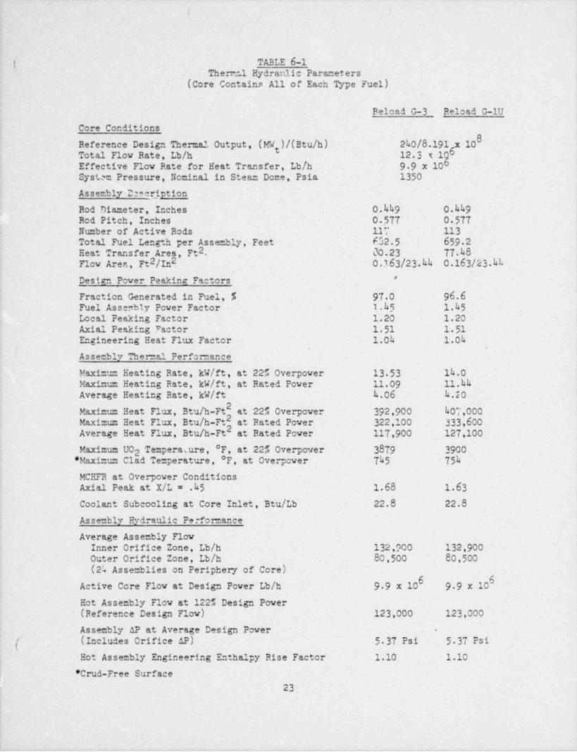
- 6.0 THERMAL HYDRAULIC DESIGN .
The hydraulic design of the reload G-3 asse=blies is identical to thatof the reload G-lU assemblies. The thermal performance of reload G-3
fuel differs slightly from reload G-lU in that the average rod power
has changed since the four cobalt corner rods have been replaced withlov enrichment UO fuel rods. This has led to a decrease in average rod
2power, consequently'it has also led to a decrease in maximum overpowerclad and fuel te=peratures and an increase in the overpower minimum
i -itical heat flux ratio. A comparison of the thermal hydraulic pa-
rameters for complete cores of reload G-3 and reload G-lU fuel assem-blies is contained in Table 6-1.
*, .,
Although Cycle 15 vill be predominantly 11 x 11 reload G-type fuel as-| semblies, approximately 25% of the core vill be 9 x 9 reload F fuel
assemblies. However, the maximum radial peaking factor for the reload F
fuel for Cycle 15 is expected to be 0.8h. This vill result in a 122%rated power minimum critical heat flux ratio of greater than 2.0 for
!+
s=all and large orifice channel loct.tions. Therefore, mini =um critical
heat flux ratio units for reload F fuels will not limit core power op-
erations for Cycle 15
,
,
)-
I |l.
22|1
i
.
. __ .m , _ ._y, y _ ,,_y, ,
, . . ~. _
.
'4
'( TABLE 6-1Therer.1 Hydraulic Parameters'
(Core Contains All of Each Type Fuel) i
Reload G-3 Reload G-lU
Core Conditions !
Reference Design Themal Output,- (MW )/(Btu /h) 2h0/8.191t 6Total Flow Rate, Lb/h 12.3xigEffective Flow Rate for Heat Transfer, Lb/h. 9 9 x 10
. System Pressure, Nominal in Steam Dome, Psia 1350
Assembly 22*er_iption-Rod Diameter, Inches 0.kh9 0.hh9
[ Rod Pitch, Inches 0 577 0 577-Number of Active Rods 117 113.
Total Fuel Length per Assembly, Feet. 652.5 659.22Heat Transfer Area, Ft . 00.23 77.h8
2 2 0.163/23.hh 0.163/23.hkFlow Arer., Ft /In*Design Power Peaking Factors
Fraction Generated in Fuel, % 97 0 96.6Fuel Asserbly Power Factor 1.h3 1.h5Local Peaking Factor 1.20 1.20Axial Peaking Factor 1 51 1 51Engineering Heat Flux Factor 1.0h 1.0h
y . .
1 Assembly Thermal Performance
Maximum Heating Rate, kW/ft, at 22% Overpower 13 53 1h.0Maximum Heating Rate, kW/ft, at Rated Power - 11.09 11.hkAverage Heating Rate, kW/ft h.06 h.20
Maximum Heat Flux, Btu /h-Ft at 22% Overpower 392,900 h07,000Maximum Heat Flux, Btu /h-Ft at Rated Power 322,100 333,600
2Average Heat Flux, Btu /h-Ft at Rated Power 117,900 127,100
Maximum UO2 Temperasure, *F, at 22% Overpower 3879 3900' Maximum Clad Temperature, *F, at Overpower Th5 75h
; MCHFR at Overpower ConditionsAxial Peak at X/L = .h5 1.68 1.63Coolant Subcooling at Core Inlet, Btu /Lb 22.8 22.8Assembly Hydraulic Perfomance
Average Assembly FlowInner Orifice Zone, Lb/h 132,900 132,900
80,500 80,500Outer Orifice Zone, Lb/h -
(2k Assemblies on Periphery of. Core)6 6Active Core Flow at Design Power Lb/h 9 9 x 10 9 9 x 10
Hot Assembly Flow at 122% Design Power(Reference Design Flow) 123,000 123,000
Assembly AP at Average Design Power -
[ (Includes Orifice AP) 5 37 Psi 5 37 Psi
j Hot Assembly Engineering Enthalpy Rise Factor 1.10 1.10
' Crud-Free Surface[,
L 23 li. 1
.
,. -. ,. - , . . -
!'
I
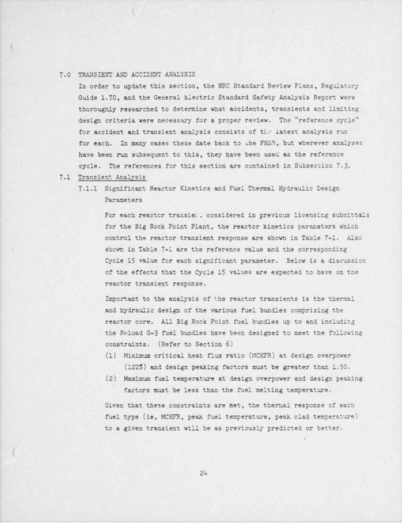
70 TRANSIENT AND ACCIDENT ANALYSIS
In order to update this section, the NRC Standard Review Plans, RegulatoryGuide 170, and the General Electric Standard Safety Analysis Report were
thoroughly researched to determine what accidents, transients and liniting
design criteria were necessary for a proper review. The " reference cycle"for accident and transient analysis consists of th' latest analysis run
for each. In many cases these date back to the FHSR, but wherever analyses
have been run subsequent to this, they have been used as the reference
cycle. The references for this section are contained in Subsection 7 3
71 Transient Analysis
T.1.1 Significant Reactor Kinetics and Fuel Thermal Hydraulic Design
Para =eters
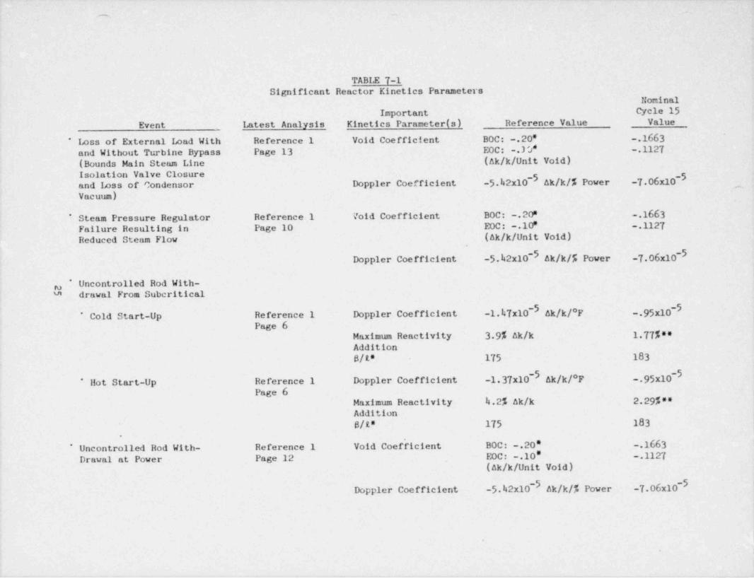
For each reactor transiet considered in previous licensing submittals
for the Big Rock Point Plant, the reactor kinetics parameters which
control the reactor transient response are shown in Table 7-1. Also,
! shown in Table 7-1 are the reference value and the corresponding
Cycle 15 value for each significant parameter. Below is a discussion
of the effects that the Cycle 15 values are expected to have on the
reactor transient response.
Important to the analysis of the reactor transients is the the. 21
and hydraulic design of the various fuel bundles comprising the
reactor core. All Big Rock Point fuel bundles up to and including
the Reload G-3 fuel bundles have been designed to =eet the following
constraints. (Refer to Section 6)(1) Minimum critical heat flux ratio (MCHFR) at design overpower
(122%) and design peaking factors must be greater than 1.50.(2) Maximum fuel temperature at design overpower and design peaking
,
factors must be less than the fuel melting temperature.
Given that these constraints are met, the thermal response of each
fuel type (ie, MCHFR, peak fuel temperature, peak clad temperature)to a given transient vill be as previously predicted or better.
.
(.
2h
-.
-
., ..-
TABLE 7-1Significant Reactor Kinetics Parameters
NominalImportant Cycle 15
Event Latest Analysis Kinetics Parameter (s) Reference Value Value
Loss of External Load With Reference 1 Void Coefficient BOC: .20' .1663*
and Without Turbine Bypass Page 13 EOC: . 3 0* .112T
(Bounds Main Steam Line (ak/k/ Unit Void)Isolation Valve Closure -5and Loss of Condensor Doppler Coefficient -5.h2x10- Ak/k/% Power. -7 06x10 ,
Vacuum) .
Steam Pressure Regulator Reference 1 Void Coefficient BOC: . 20" .1663*
Failure Resulting in Page 10 EOC: .10F . .1127Reduced Steam Flow (ak/k/ Unit Void)
-5Doppler Coefficient -5.42x10⁻⁵ ak/k/5 Power -7 06x10
* Uncontrolled Rod With-g'a drawal From Suberitical
-5 -5* Cold Start-Up Reference 1 Doppler Coefficient -1.47x10 ak/k/*F .95x10
Page 6Maximum Reactivity 3.9% ak/k 1 77%**Addition
S/t* 175 183
-5 -5* Ilot Start-Up Reference 1 Doppler Coefficient -1.37x10 Ak/k/*F .95x10
Page 6Maximum Reactivity 4.2% ak/k 2.29%**Addition
S/t* 175 183
Uncontrolled Rod With- Reference 1 Void Coef'icient- BOC: .20' .1663f*
Drawal at Power Page 12 EOC: .10' .1127(ak/k/ Unit Void)
-5Doppler Coefficient -5.42x10- ak/k/% Power -7 06x10
I.
.
_ _ _ _ . _ _ _ _ - _ _ _
. _ _. _ _.
' ,ah
,
TABLE 7-1 (Contd) ''
<
Nominal-Important Cycle 15
. Event Latest Analysis Kinetics Parameter (s) Reference Value Value.
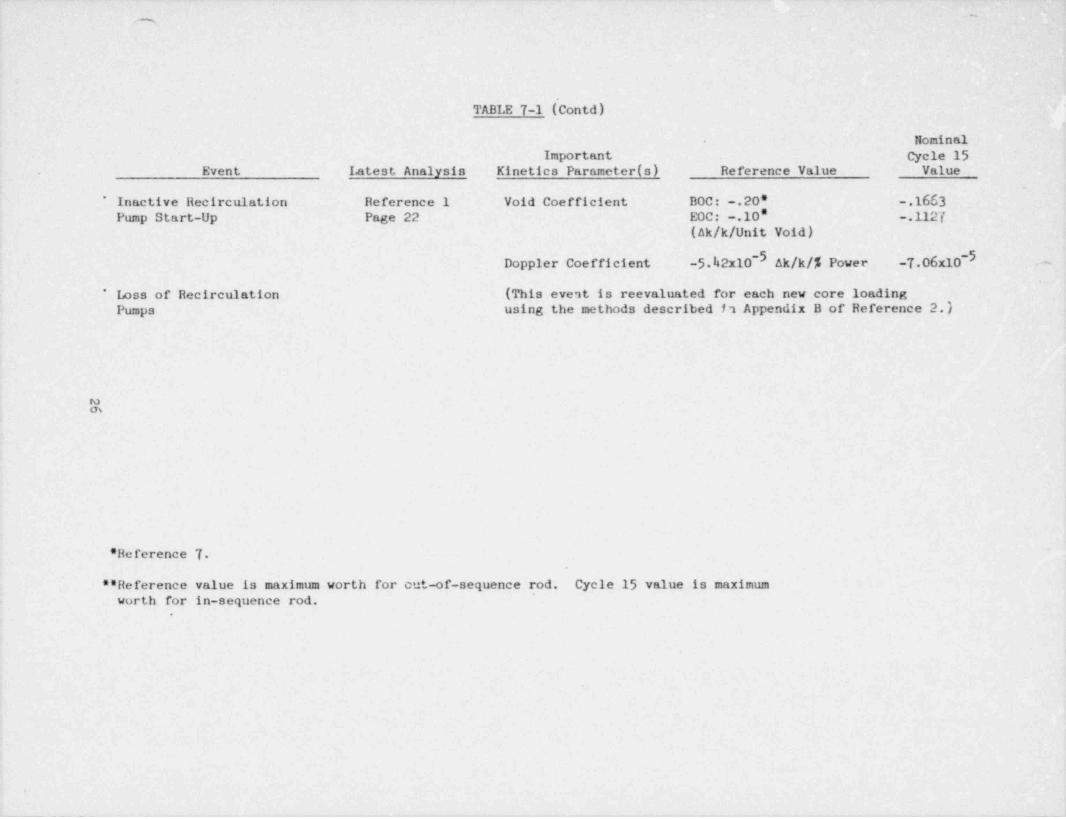
* Inactive Recirculation Reference 1 Void. Coefficient BOC: .20' .1663Pump Start-Up Page 22 EOC: .10' .1127
(Ak/k/ Unit Void)
-5.12x10 ak/k/5 Power -T.06x10 '-5 ~
Doppler Coefficient 6 e
* Loss'of Recirculation (This event is reevaluated for each new core loading
Pumps using the methods described h Appendix B of Reference 2.)
S
' Reference T.~
'' Reference value is maximum worth for cut-of-sequence rod. Cycle 15 value is maximumworth for in-sequence rod.
.
_ _ _ _ _ _ _ _ _ _ _- - - -
_____
k
l
,
!
i
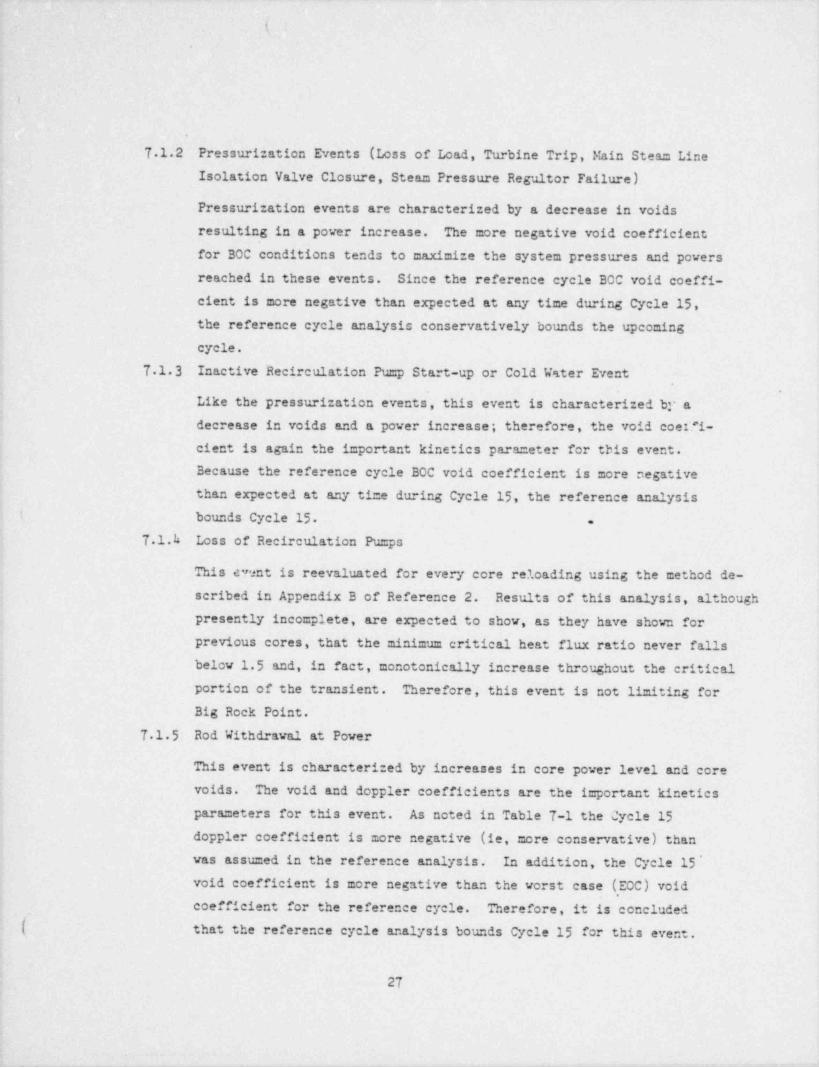
7 1.2 Pressurization Events (Loss of Load, Turbine Trip, Fain Steam LineIsolation Valve Closure, Steam Pressure Reguitor Failure)
Pressurization events are characterized by a decrease in voidsresulting in a power increase. The more negative void coefficientfor BOC conditions tends to maximize the system pressures and powersreached in these events. Since the reference cycle BOC void coeffi-cient is more negative than expected at any time during Cycle 15,the reference cycle analysis conservativel'y bounds the upcomingcycle.
7.1.3 Inactive Recirculation Pump Start-up or Cold Wster Event*
.
Like the pressurization events, this event is characterized br adecrease in voids and a power increase; therefore, the void coeffi-
cient is again the i=portant kinetics parameter for tbis event.
Because the reference cycle BOC void coefficient is more negativethan expected at any time during Cycle 15, the reference analysis
i. bounds Cycle 15 -
7 1.h Loss of Recirculation Pu=ps
This c?ent is reevaluated for every core reloading using the method de-scribed in Appendix B of Reference 2. Results of this analysis, althou6h
presently incomplete, are expected to show, as they have shown forprevious cores, that the minimum critical heat flux ratio never fallsbelow 15 and, in fact, monotonically increase throughout the criticalportion of the transient. Therefore, this event is not limiting forBig Rock Point.
7 1.5 Rod Withdrawal at Power
This event is characteri:ed by increases in core power level and corevoids. The void and doppler coefficients are the important kineticsparameters for this event. As noted in Table 7-1 the Cycle 15doppler coefficient is more negative (ie, more conservative) thanwas assu=ed in the reference analysis. In addition, the Cycle 15 'void coefficient is more negative than the worst case (EOC) void
,
coefficient for the reference cycle. Therefore, it is concluded(. that the reference cycle analysis bounds Cycle 15 for this event.
27

,
i$_
,
,
.
.
7 1.6 Start-Up Event
The start-up event (or the uncontrolled rod withdrawal fro = sub-critical) was maaly:ed in Reference 1 for both the cold and hotstandby initial conditions. The start-up event is characterizedby an extre=ely rapid increase in nuclear power (to approxicately100 times rated pover) followed by an equally rapid power reductiondue to doppler feedback. The important kinetics para =eters forthis event are the doppler coefficient, the ratio of BETA /t*,and the =aximum reactivity addition due to the withdrawal of acontrol rod while suberitical. As noted in Table T-1 only theCore 15 doppler coefficient is significantly nonconservative asco= pared to the values assu=ed in the reference analysis. Thema dmu= reactivity addition is =uch less than assu=ed for thereference analysis, and the BETA /t* ratio is nearly the same asassumed in the reference analysis. If, however, the event were
I reanaly:ed assu=ing the Cycle.15 value for the doppler coefficientand assu=ing the sa=e rod worths and BETA /i* ratios as in the ref-erence analysis, the consequences of this accident would still notbe severe. Assuming a linear relatiouship between doppler coeffi-cient and fuel effective temperature rise, the reduced Core 15 dopp-1er coefficient would result in full effective te=perature rises of900*F and 850 F (as co= pared to 580*F and 590*F in the referenceanalysis) for the cold and hot start-up events, respectively.
Thus, assu=ing a hot spot peaking factor of 3 0, the peak fuelte=peratures of 2800 F and 3100 F for the cold and hot start-upevents, respectively, vould still be significantly less than thefuel =elting te=perature. This is still extre=ely conservative sincea hot spot peaking factor of 3 0 is significantly greater than villbe allowed during Cycle 15 based on Eccs li=itations.
72 Accident Analysis
T . 'i .1 Loss of Coolant Accident (LOCA)
The Big Rock Point Loss of Coolant Accident analysis 'for Exxen Nuclear
( Co=pe.ny (ENC) fue) was perfor=ed with E'iC calculational =edels which
28 .
|!
4
--. - . . _ . ,
_. _
'
t ,
.
I5
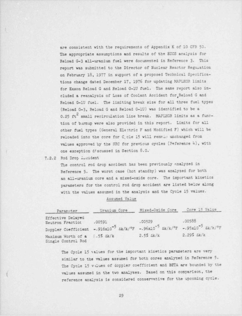
are consistent with the requirements of Appendix K of 10 CFR 50.
The appropriate assumptions and results of the ECCS analysis for
Reload G-3 all-uranium fuel vere documented in Reference 3 This
report was submitted to the Director of Nuclear Reactor Regulation~
on February 18, 1977 in support of a proposed Technical Specifica-tions change dated Dece=ber 17, 1976 for updating MAPLHGR limits
' for Exxon Reload G and Reload G-1U fuel. The same report also in-
cluded a reanalysis of Loss of Coolant Accident for, Reload G andReload G-lU fuel. The limiting break size for all three fuel types
(Reload G-3, Reload G and Reload G-1U) was identified to be a20.25 ft small recirculation line break.' MAPLEGR limits as a fune .-
tion of barnup were also provided in this report. Limits for allother fuel types (General Ele:tric F and Modified F) which will bereloaded into the core for Cfele 15 vill remr.in unchanged fromvalues approved by the NRC for previous cycles (Reference k), with'
{one exception discussed in Section 8.0.'
7.2.2 Rod Drop AscidentThe control rod drop accident has been previously nnalyzed in
Reference 5 The worst case (hot standby) was analyzed for both4 an all-uranium core and a mixed-oxide core. The important kinetics
parameters for the control rod drop accident are listed below alongwith the values assumed in the analysis and the Cycle 15 values.
Assumed Value
Parareter Uranium Core Mixed-Oxide Core Core 15 Value
Effective Delayed
Neutron.Fractiot .00591 .00529 .00588~I
-Doppler Coefficient .916x10"' ak/k/*F .96x10'' ak/k/*F .95x10 ak/k/*F
Maximum Worth of a it.5% ak/k 2.5% ak/k 2.29% ak/k'
Single Control Rod
The Cycle.15 s alues for the important kinetics parameters are very'
similar to the values assuned for both cores analyzed in Reference 5The Cycle 15 v tlues of doppler coefficient and BETA are bounded by the
( values assumed in the two analyses. -Based on this comparison, thereference analysis is considered conservative for the upec=ing cycle.
~
;
i
29
I_ _ - - _. .
_ . . . . , ... __
(,
t
.
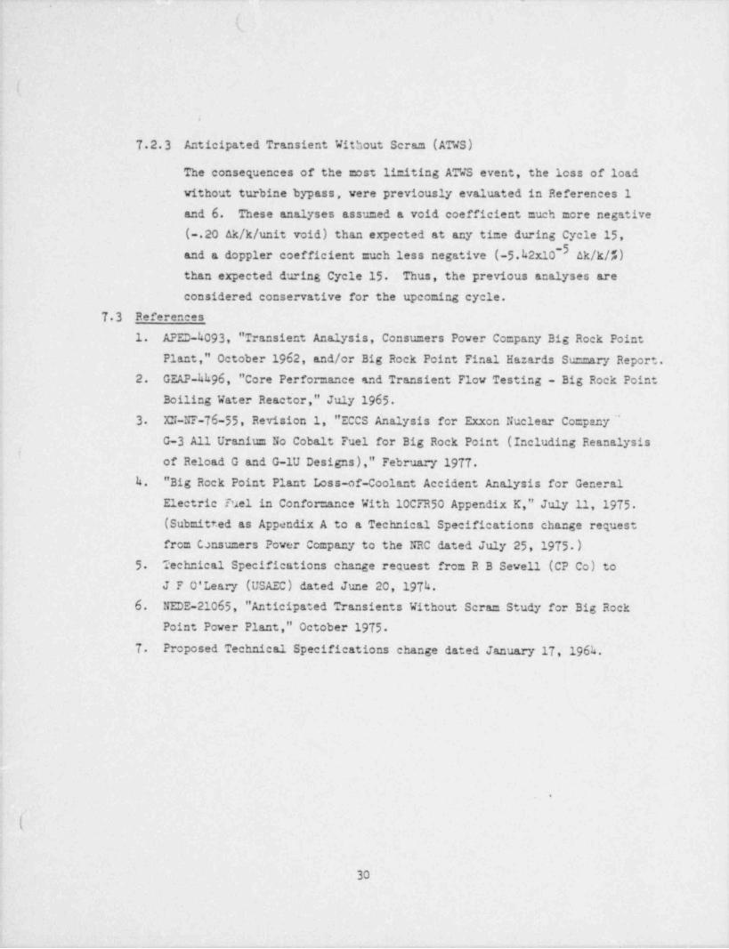
7.2.3 Anticipated Transient Without Scram (ATWS)
The consequences of the most limiting ATWS event, the loss of load
without turbine bypass, were previously evaluated in References 1
and 6. These analyses assu=ed a void coefficient much more negative( .20 Ak/k/ unit void) than expected at any ti=e during Cycle 15,
-3and a doppler coefficient much less negative (-5.k2x10 ak/k/7.)than expected during Cycle 15 Thus, the previous analyses are
considered conservative for the upcoming cycle.
73 References1. APED-h093, " Transient Analysis, Consumers Power Company Big Rock Point
Plant," October 1962, and/or Big Rock Point Final Ha::ards Su==ary Report.2. GEAP kh96, " Core Performance snd Transient Flow Testing - Big Rock Point
Boiling Water React'or," July 1965
3 XN-NF-76-55, Revision 1, "ECCS Analysis for Exxon Nuclear Co=pany "G-3 All Uranium No Cobalt Fuel for Big Rock Point (Including Reanalysisof Reload G and G-1U Designs)," February 1977
h. " Big Rock Point Plant Loss-of-Coolant Accident Analysis for GeneralElectric Tuel in Confor=ance With 10CFR50 Appendix K," July 11, 1975(Submitted as Appendix A to a Technical Specifications change requestfrom Consumers Power Company to the NRC dated July 25,1975.)
5 Technical Specifications change request from R B Sewell (CP Co) toJ F O' Leary (USAEC) dated June 20, 197h.
6. NEDE-21065, " Anticipated Transients Without Scram Study for Big RockPoint Power Plant," October 1975
7 Proposed Technical Specifications change dated January 17, 196h.
.
(
30

- -
. ..
( '
.
l .
!
8.0 PROPOSED MODIFICATIOUS TO TECICIICAL SPECIFICATIONS
The proposed Technical Specifications are contained under Section I ofthis submittal. In general, the changes consist of proposing specificparameters and drawings for the Reload G-3 fuel for the Bic Rock PointTechnical Specifications with justification presented in Sections 1through 7 The MAPLHGR limits, as proposed, are consistent with the pro-
posed MAPLHGR limits contained in the Technical Specifications changeI
request dated December 17, 1976. Justification for these limits is con- |
tained in Exxon Report XN-NF-76-55, Revision 1, forwarded to the Commissionon February 18, 1977 There is also a minor correction to the MAPLEGR formodified F fuel '.t a burnup of 25,000. By letter dated July 25, 1975, weproposed a MAP'.HGR limit of 8.14. In Amend =ent 10, dated June k, 1976, this
value was incorrectly transposed to 8.7 We propose to correct this back
to 8.*.
One proposed change to the Technical Specifications has not been addressedup to this point. That change is the deletion, from Section 5 2.l(b) and'
Table 8.2, of the limitation for the " Maxi =um !&d/T of Contained Uraniu= foran Individual Bundle." This limitation first appeared in Consu=ers Power
proposed Technical Specifications for the Big Rock Point Plant dated June 1,1962. It was contained in Section 5 2.2, " Principal Calculated Nuclear Char-acteristics of the Core." This section contained specific para =eters relevant
to Cycle 1 for the Big Rock Point reactor (eg, moderator and void coefficients,topplers, reactivity balance, average igd / Ton of contained uranium, etc). Itis apparent that although the other design parameters associated with theoriginal core composition vere updated or deleted as necessary to accountfor the different reload fuels, the limitation on maximum fuel burnout was
maintained intact for each subsequent reload licensing submittal.
By letter dated January 20, 1577, Consumers Power Company responded to aletter from Mr D L Zie= ann concerning fission gas release from fuel pellets
with high burnup. In our response, we calculated the relevant parameters
for all G series reload fuels for burnups ranging from 30,620 to 38,935!Gd/MT. This is well above the design burnup of the fuels.. The results
( of this analysis indicated that the fission gas release modQ burnup had
31 4
. .
- - - - - - - - - . _ - - - - _ - . . - _ _
(' _
(
very little effect on the peak clad te=perature prediction (less than 1%reduction in MAPLHGR limits at end of life) and consequently insignificanteffect on the Big Rock Point LOCA analysis and, therefore, was of no safetyconcern. We further indicated that these results vould be consistent forthe 9 x 9 fuels.
Attached as Appendix 1 to this report is an analysis of the fission productinventory change with increased burnup for the Big Rock Point core. Thisanalysis was conducted assuming a core average burnup of 30,000 WD/STU, whichis also higher than the design average burnup of the Reload G fuel. The resultsof this analysis indicated that the radiation dose increases due to in-
creased fission product inventory were insignificant and would remain in-significant (less than 1% of total dose) until tr e fuel burnups reached
6approximately 15 x 10 Wd/T.
~ Further justification for deletion of the maximum burnup limitation existsin the Standard Review Plans. Section h.2 states in part, "The claddingdesign should be such as to acco=rodate the fission gas evolved in opera-
! tion, so that the fuel can reach design burnup without exceeding thecladding structural design criteria." By virtue of the preceding dis-cussion and analyses, Consu=ers Power Company concludes that it adequatelymeets the Standard Review Plan criteria and therefore no arbitrary bumupli=itation is necessary. Also, the General Electric Standard TechnicalSpecifications for Boiling Water Reactors makes no mention of the maximu=fuel burnup allovable. Since Big Rock Point is in the process of conver-,
sion to the standard for=at, we feel that consistency would also dictatedeleting this arbitrary limitation.
Thus, based on safety analyses performed concerning fuel burnup and onguidance developed from the Nuclear Regulatory Cc==ission in the fom ofthe Standard Reviev Plans and Standard Technical Specifications, Consu=ers
Pcver Cc=pany concludes that the li=itation on maximu= fuel burnup is un-necessary and should be deleted from the Big Rock Point Technical Epeci-fications.
.
32
. i'
.
(
9.0 START-UP PROGRAM
The testing and start-up program planned for the next refueling outageand subsequent start-up vill include:
(1) Control rod drive testing, as required by the Technical Specifica-tions, including scram times.
(2) Core shutdown margin verification with the most reactive rod with-drawn.
(3) Critical control rod pattern.(k) Measure =ent of flux shapes during power escalation and co=parison
to ce=puter predictions.
A brief explanation of these tests is contained below..
Shutdown Margin Verification:
Core shutdown margin is verified at the beginning of each cycle and dur-
ing the first cold shutdown after 35,000 MWde generation. The TechnicalSpecifications require su'ocriticality to be demonstrated with the mostreactive rod withdrawn from the core as well as an im=ediately adjacent
rod known to contribute .003 k,ff or more. Ar analytical determination
of the highest worth rod is made, as well a.= the number of notches of anic=ediately adjacent rod required to contribute .6% ak/k. 35 ak/k isadded to account for a reactivity increase at temperatures higher thanthe ambient te=perature at which the test is performed (nor= ally 10d to204). Plant procedures call for the individual vithdrawal of each controlrod in the core, tius at least the nu=ber of r.otches specified in the
p'hysics analysis on an sijacent rod to verif t the analytical determination.Core monitoring is provided by gas-filled B sron 10 lined proportionalcounters and may be supple =ented by portalle fission chambers positionedabove the core when available count rate is lov. .
Rod Drive Scrsm Time Testing:
Technical Specifications requirements state the maximu= control rod drive
scram time from the fully withdrawn position to 90% of insertion shall
not exceed 2.5 seconds. This require =ent is verified at the beginning ofeach cycle by attaching leads from a strip chart recorder traveling at a
predetermined rate to the position indication for the drive to be tested
[ and to the 26 volt d-c signal from the high reactor pressure input on one
33
,
|-
\
!
__
\ I
.
k
of the two safety channels. The control rod is fully withdrawn and ahidt reactor pressure trip is simulated by removing power from the reac-tor pressure input to the safety system logie circuMry. Scram ti=e isme asured on the strip chart from the time of safety channel trip to fullAnsertion. The test is repeated for all control rods using both safetychannels.
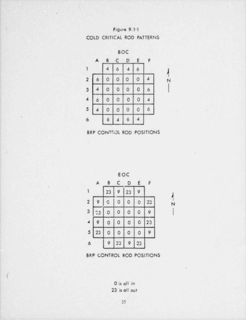
Critical Rod Pattern:
Control. rod withdraval sequences and initial critical rod patterns areanalytically determined at the beginning of each cycle. La completionof core reconstitution and shutdown margin verification, an initial
criticality at ambient conditions is performed. Integrated control rodworth curves and shutdown margin are adjusted based on the conditionsof actual critical rod pattern. On attaining steady state equilibrium
conditions at rated power, a reactivity balance is performed and the ac-tual critical rod pattern is verified to be within 15 ak/k of expected.
,
Figure 91-1 shovs the cold critical control rod pattern at BOC and EOC.,
Power Eistribution Measurement:Flux aistribution measurements are me.de during the escalation to rated
power after the beginning of a new cycle by inserting of copper-titaniu=alloy wires into the core and counting the copper activation. Predictionsof this flux vire activation are made with GROK, a three-dimensional one
group diffusion theory code, using actual operating conditions as input.
(See Section 5.2.)Power distribution calculations are then adjusted based on the flux vire,
GROK calculation comparison. In-core instrumentation is calibrated toconform with flux vire measurements. Ther=al hydraulic analysis based
on the flux vire corrected power distribution calculations are comparedto MAPLHGR, MCHFR and heat flux limits to insure confor:.uce with the
Technical Specifications.
.
k
(
3k
.
,
t'
.
.
I Figure 9.11,
COLD CRITICAL ROD PATTERNS
BOC
A B C D E F
1 4 6 4 6J
2 6 0 0 0 0 4 N
3 4 0 0 0 0 6
4 6 0 0 0 0 4
5 4 0 0 0 0 6'
6 6 4 6 4
BRP CONTP0L ROD POSITIONS
*
;
EOC
A B C D E F.
I 23 9 23 9)
2 9 0 0 0 0 23 N
3 23 0 0 0 0 9
4 9 0 0 0 0 23
5 23 0 0 0 0 9'
6 9 23 9 23
BRP CONTROL ROD POSITIONS
|*
( ||
|~
0 is all in| 23 is all out
35

. _ - .. ..
. ( *
*
.
'
(
III. CONCLUSIONS*
Based on the foregoing, Big Rock Point Plant Review Co:::mittee has con-cluded that this change does not involve an unreviewed safety question.
CONSUMERS POWER COMPANY
ByC R Bilby, Vice Pr @ entPr;**tetion & Transmitsion
Sworn and subscribed to before me this 15th day of April 1977
L.J)< % 0/r'1) 'k k??/[4 )-
Linda R Thayer, Notary PublicJackson County, Michigan
My com.ission expires July 9, 1979
. .
g'
1
I
',
.
36
., ._ ._ _ _ _
__ _
''
.
.
Appendix 1
(
FISSION PRODUCT INVENTORY CHANGEWITH INCREASED BURNUP - BIG ROCK POINT
PACKGROUND
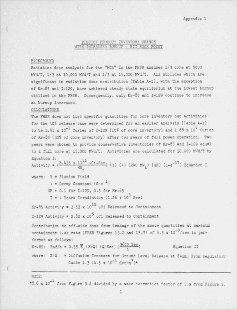
Radiation dose analysis for the "MCA" in the FHSR assumes 1/3 core at 5000Wd/T,1/3 at 10,000 Wd/T and 1/3 at 15,000 Wd/T. All nuclides which aresignificant in radiation dose contribution (Table A-1), with the exceptionof Kr-85 and I-129, have achieved steady state equilibrium at the lowest burnuputilized in the FHSR. Consequently, only Kr-85 and I-129 continue to increaseas burnup increases.CALCULATIONS
'
The FHSR does not list specific quantities for core inventory but activitiesfor the 10% release case were determined for an earlier analysis (Table A-1)
to be 1.kl x 10 Curies of I-129 (10% of core inventon) and 1.88 x 10 Curies-
of Kr-85 (30f, of core inventory) after two years of full power operation. Twoyears were chosen to provide conservative inventories of Kr-85 and I-129 equalto a full core at 15,000 Wa/T. Activities are calculated for 30,000 Wd/T byEquation I: .g
Activity = (8.h35 x ) (Y) ( A) (2ho W ) (GR) (1-e ) Equation I0 uci-set
t
where: Y = Fission Yield
A = Decay Constant (Sr.c )
GR = 0.1 for I-129, 0 3 for Kr-85
T = k Years Irradiation (1.26 x 10 Sec)10Kr-85 Activity = 3 53 x 10 pCi Released to Containment
I-129 Activicy = 2.82 x 10' uCi Released to Containment
Contributier to off-site dose from leakage of the above quantities at maxiem
containment 1sak rate (FHSR Figures 13.2 and 13.3) of h.3 x 10-9/see is per- |
formed as follows: |
Rad /h = 0 35 % (X/Q) (Q/See) (3600) Equation IIKr-85: h
where: X/Q = Diffusion Censtant for Ground Level Release at 8h2m, From Regulatory3 '-
Guide 1.3 (4.5 x 10 Sec/m )*
NOTE:
*8.6 x 10 ' froc Figure 3.A divided by a wake correction factor of 19 fre: Figure 2. |
1
.-. . ,. .
i I*l
|*
|
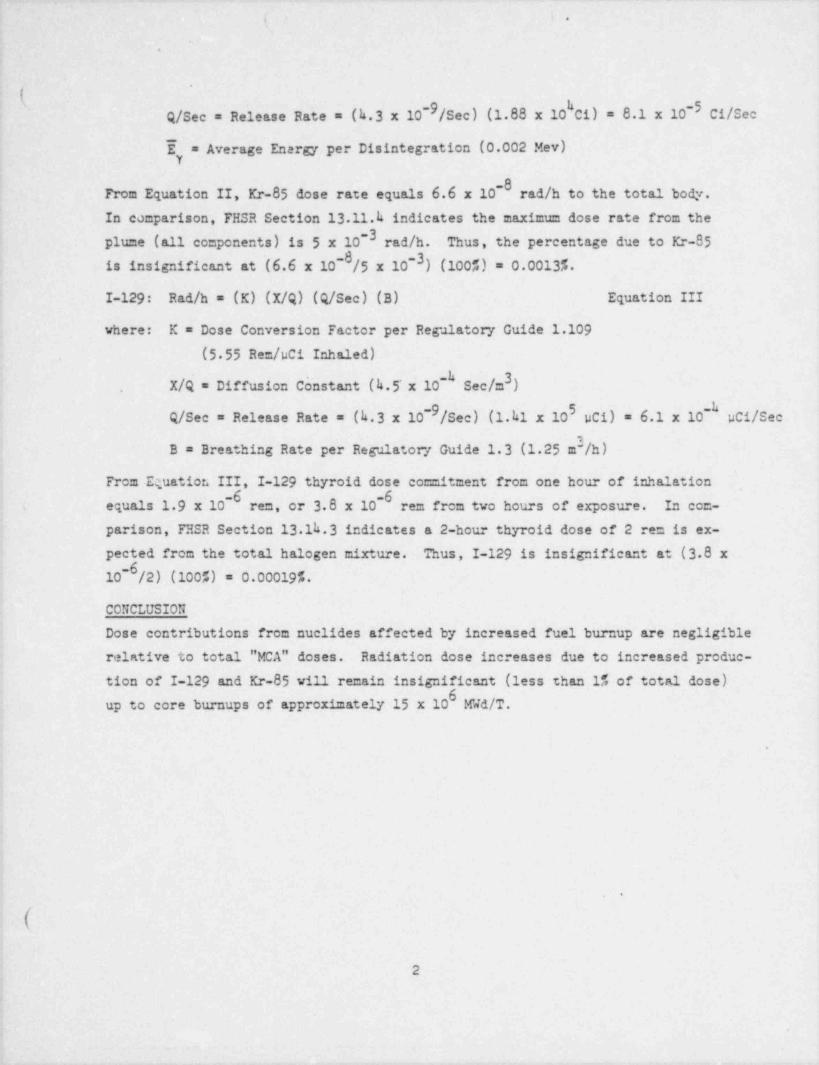
~ -9/Sec) (1.88 x 10 Ci) = 8.1 x 10⁻⁵ cifs,cQ/Sec = Release Rate = (k.3 x 10
E = Average Energy per Disintegration (0.002 Mev)Y
-0From Equation II, Kr-85 dose rate equals 6.6'x 10 rad /h to the total body.In comparison, FHSR Section 13.11.h indicates the maximum dose rate from theplume (all conponents) is 5 x 10⁻³ rad /h. Thus, the percentage due to Kr-85is insignificant at (6.6 x 10 /5 x 10-3) (100%) = 0.00135.
I-129: Rad /h = (K) (X/Q) (Q/Sec) (B) Equation III
where: K = Dose Conversion Factor per Regulatory Guide 1.109
(5 55 Rem /uci Inhaled)3X/Q = Diffusion Constant (h.5'x 10- Sec/m ),
-9 5 -Q/See = Release Rate = (h.3 x 10 /See) (1.h1 x 10 pC1) = 6.1 x lo pCi/See
1B = Breathing Rate per Regulatory Guide 1.3 (1.25 m-/h)
From Equatier. III, I-129 thyroid dose commitment from one hour of inhalation-6 6-
i equals 1 9 x 10 rem, or 3.8 x 10 re= from two hours of exposure. In com-
parison, FHSR Section 13.1h.3 indicates a 2-hour thyroid dose of 2 ren is ex-pected from the total halogen mixture. Thus, I-129 is insignificant at (3.8 x10 /2) (1005) = 0.00019%.
CONCLUSION
Dose contributions from nuclides affected by increased fuel burnup are negligible
relative to total "MCA" doses. Radiation dose increases due to increased produc-tion of I-129 and Kr-85 vill remain insignificant (less than 1% of total dose)
0up to core burnups of approximately 15 x 10 mwd /T.
.
a @
2
a
.
4
. . _ _ _ _ _ _ .. . . . _ _ _ .._. -- .. _ . __ . _ _ _. ._
,
{ t
,.
'.
'
(,
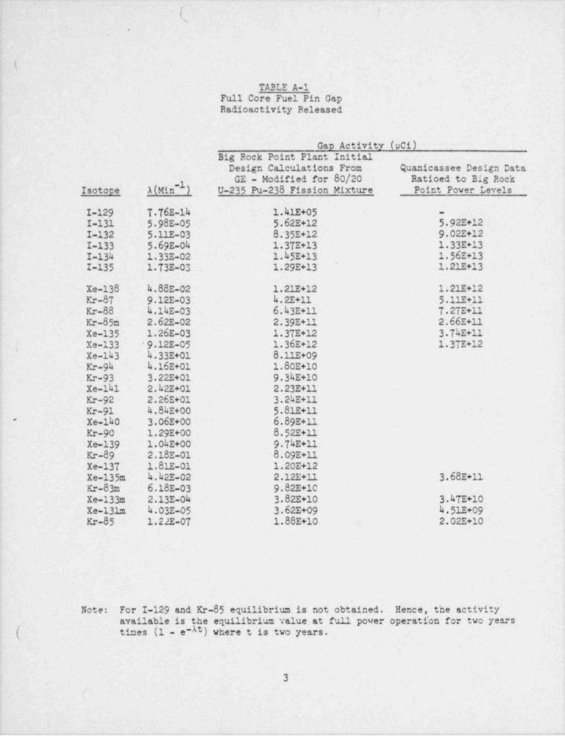
-TABLE A-1'
Full Core Fuel Pin Gap i
( Radioactivity Released
Gap Activity (pCi)
Big Rock Point Plant InitialDesign Calculations From Quanicassee Design DataGE - Modified for 80/20 Ratioed to Big Rock
' Isotope- 1(Min 1) U-235 Pu-238 Fission Mixture Point Power Levels--
I-129 T.T6E-14 1.41E+05 -
I-131 5 98E-05 5.62E+12 5 92E+12I-132 5 11E-03 8.35E+12 9 02E+12I-133 5 69E-Oh 1.37E+13 1.33E+13I-134 1.33E-02 1.k5E+13 1.56E+13
'
.I-135 '1 73E-03 1.29E+13 1.21E+13
.Xe-138 4.88E-02 1.21E+12 1.21E+12Kr-87 9 12E-03 k.2E+11 5.11E+114
Kr-88 k.1kE-03 6.k3E+11 T.2TE+11Kr-85m 2.62E-02 2.39E+11 2.66E+11
I Xe-135 1.26E-03 1.37E+12 3.TkE+11|. Xe-133 '9 12E-05 1.36E+12 1.3TE+12
Xe-143 k.33E+01 8.11E+09'
Kr-9h k.16E+01 1.80E+10Kr-93 3.22E+01 9 3kE+10Xe-141 2.k2E+01 2.23E+11Kr-92 2.26E+01 3.2kE+11Kr-91 k.8kr+00 5.81E+11Xe-1k0 3.06E+00 6.89E+11'
Kr-90 1.29E+00 8.52E+11Xe-139 1.04E+00 9.TkE+11Kr-89 2.18E-01 8.09E+11Xe-137 ~1.81E-01 1.20E+12Xe-135m k.k2E-02 2.12E+11 3.68E+11Kr-83m 6.18E-03 9.82E+10Xe-133m 2.13E-04 3.82E+10 3.kTE+10.Xe-131a 4.03E-05 3.62E+09 k.51E+09
j Kr-85 1.22E-07 1.88E+10 2.02E+10
Note: For I-129 and Kr-85 equilibrium is not-obtained. Hence, the activityavailable is.the equilibrium value at full power operati'on for two years
( times (1 - e-At) where t is two years.'
3
ri'
.
r - , -. 4 - ,w--. .%. -. # _ .y-- .w-s-,-e- --, -.- y- 3- . m
.. m , _ ..,' " " " " "
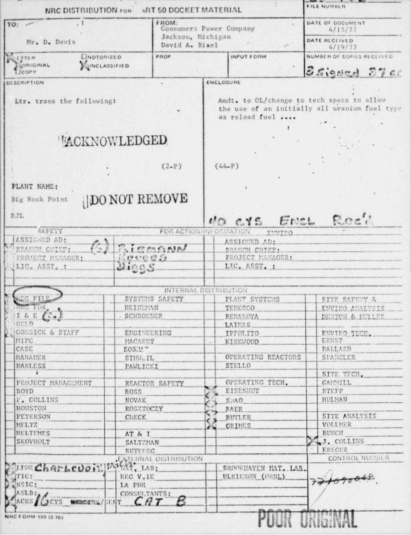
NRC DISTRIBUTION ron (RT 50 DOCKET M ATERI Al.
T'''. , , - ,i FROM: DATE or DOCUMENT-
.
Consumers Power Company 4/15/77'
Jackson, Michigan '
Mr. D. Davis oAtt ntcovc o*David A. Bixel .* 4/19/77
TTEn CNOTonl2ED PnoP |NPUT FOnM NUMDEn or CoPfLS RECLIVE D
(onIGIN A L JNCLASSIFl[o . g *y ,,; g p y y Q *j c f9JCOPY
ENCLoSUHLDLSCnlPTioN .
,Ltr. trans the following: Amdt. to OL/ change to tech specs to allowthe use of an initially all uranium fuel type.
"
as reload fuel ...... .
! -'
,
: !%CKNOWLEDGED. ".. . .-
.
.
'
..
.
j (2-P) (44-P)'
'
.
''
. .
PLANT NAME: i,
'' p0 NOT REMOVEig Rock Pointt
h NY bJ F .O .
RAFETY FOR ACTION /INi-ORM ATION p yLt;O'
ASSIGNED AD: # ASSIGl:ED_AD *bERAUClLCHIEI': l 'y,._
_
U-h.l._Cfaft "3 M
_ nRI.UCIL. CHIEF: --
'
'IPRO,1ECT M'.NACt;R: eX-QC 73 PROJECT 1'A??ACER:'
d)_[of.s $LIC, ASST. :Ay LIC ,_ A S ST., :
w
i INTERNAL DISTRIBUTIONY, iQFIIT SYSTEMS SAFETY PLANT SYSTEMS SITE SAFF.TY_AY.l! M IM llE.IIIEl'4!! TEDESCO EWIn0_/J!ALYSIS_,I ilI & E hy_t . SCllR0EDER EENAROYA DU;IIQ'LEda'LLEP
. ', ! OELD LAINAS --
{COSSICK& STAFF E!!GI;;EERING IPTOLIT.0 ENV T E O._.TECE.
KIRIX00D _ERNSTIIIPC MACARRY -
CASE E03'.V." 11ALLARDllANAUER SI1nh,IL OPERATING REACTORS SPANCLERllARI.ESS PAWI,IC.!;I STELLO
I SITE TEC11
_ PPfLTECT MANAGEMENT REACTOR S/fET_y OPERATING TECll. _ _ __CArplILL
._k EISENilUT STEPP{'80YD ROSS
_
110USTON__
_S;iAQ llDLMANP _ COL.LI]iS NOVAKROS7. TOC 7.Y m _J3 AEg
'' SITE ANALYSISPETEllSON CliECKh_~Elfrl,ERggig1;S V01.1.MERMELTZ
BUNCillil:1.TEMES AT & I_ ([. COLLINSEKOVil01.T SA1.TZMAN
__
'/Ri!TP.ERC KREGER*
.I YllitN AL DISllllflUTION CONI HOL NU.'. HIE R
.hION b18ElsC.Nf5[ ik _ _UR00KilAVEM. IIAT._ LAB.. 7,e
TIC: REC V.lE ULRIKSON (OltNL) y/., aR
k<mNSIC[ 1.A Pnn~ ~ '
h 7"/""~
*I
|A SI.B : CONSiti.TANTS :ACRS CYji tett.cu;/ :I[t if" ( 8 7~ [$ ~
|,
'
3g g{'
~nc r onM m im,,