chai, j., mcneilan, t.w. geotechnical considerations ...freeit.free.fr/bridge engineering...
TRANSCRIPT

Chai, J., McNeilan, T.W. "Geotechnical Considerations." Bridge Engineering Handbook. Ed. Wai-Fah Chen and Lian Duan Boca Raton: CRC Press, 2000

30Geotechnical
Considerations
30.1 Introduction
30.2 Field Exploration TechniquesBorings and Drilling Methods • Soil-Sampling Methods • Rock Coring • In Situ Testing • Downhole Geophysical Logging • Test Pits and Trenches • Geophysical Survey Techniques • Groundwater Measurement
30.3 Defining Site Investigation RequirementsChoice of Exploration Methods and Consideration of Local Practice • Exploration Depths • Numbers of Explorations • The Risk of Inadequate Site Characterization
30.4 Development of Laboratory Testing ProgramPurpose of Testing Program • Types and Uses of Tests
30.5 Data Presentation and Site CharacterizationSite Characterization Report • Factual Data Presentation • Description of Subsurface Conditions and Stratigraphy • Definition of Soil Properties • Geotechnical Recommendations • Application of Computerized Databases
30.1 Introduction
A complete geotechnical study of a site will (1) determine the subsurface stratigraphy and strati-graphic relationships (and their variability), (2) define the physical properties of the earth materials,and (3) evaluate the data generated and formulate solutions to the project-specific and site-specificgeotechnical issues. Geotechnical issues that can affect a project can be broadly grouped as follows:
• Foundation Issues — Including the determination of the strength, stability, and deformationsof the subsurface materials under the loads imposed by the structure foundations, in andbeneath slopes and cuts, or surrounding the subsurface elements of the structure.
• Earth Pressure Issues — Including the loads and pressures imposed by the earth materials onfoundations and against supporting structures, or loads and pressures created by seismic (orother) external forces.
Thomas W. McNeilanFugro West, Inc.
James ChaiCalifornia Department
of Transportation
© 2000 by CRC Press LLC

• Construction and Constructibility Considerations — Including the extent and characteristicsof materials to be excavated, and the conditions that affect deep foundation installation orground improvement.
• Groundwater Issues — Including occurrence, hydrostatic pressures, seepage and flow, anderosion.
Site and subsurface characteristics directly affect the choice of foundation type, capacity of thefoundation, foundation construction methods, and bridge cost. Subsurface and foundation condi-tions also frequently directly or indirectly affect the route alignment, bridge type selection, and/orfoundation span lengths. Therefore, an appropriately scoped and executed foundation investigationand site characterization should:
1. Provide the required data for the design of safe, reliable, and economic foundations;2. Provide data for contractors to use to develop appropriate construction cost estimates;3. Reduce the potential for a “changed condition” claim during construction.
In addition, the site investigation objectives frequently may be to
1. Provide data for route selection and bridge type evaluation during planning and preliminaryphase studies;
2. Provide data for as-built evaluation of foundation capacity, ground improvement, or othersimilar requirements.
For many projects, it is appropriate to conduct the geotechnical investigation in phases. For thefirst preliminary (or reconnaissance) phase, either a desktop study using only historical informationor a desktop study and a limited field exploration program may be adequate. The results of thefirst-phase study can then be used to develop a preliminary geologic model of the site, which isused to determine the key foundation design issues and plan the design-phase site investigation.
Bridge projects may require site investigations to be conducted on land, over water, and/or onmarginal land at the water’s edge. Similarly, site investigations for bridge projects can range fromconventional, limited-scope investigations for simple overpasses and grade separations to majorstate-of-the-practice investigations for large bridges over major bodies of water.
This chapter includes discussions of
• Field exploration techniques;
• Definition of the requirements for and extent of the site investigation program;
• Evaluation of the site investigation results and development/scoping of the laboratory testingprogram;
• Data presentation and site characterization.
The use of the site characterization results for foundation design is included in subsequent chapters.
30.2 Field Exploration Techniques
For the purpose of the following discussion, we have divided field exploration techniques into thefollowing groupings:
• Borings (including drilling, soil sampling, and rock-coring techniques)
• Downhole geophysical logging
• In situ testing — including cone penetration testing (CPT) and vane shear, pressure meterand dilatometer testing)
• Test pits and trenches
• Geophysical survey techniques
© 2000 by CRC Press LLC

30.2.1 Borings and Drilling Methods
Drilled soil (or rock) borings are the most commonly used subsurface exploration technique. Thedrilled hole provides the opportunity to collect samples of the subsurface through the use of avariety of techniques and samplers. In addition to sample collection, drilling observations duringthe advancement of the borehole provide an important insight to the subsurface conditions. Drillingmethods can be used for land, over water, and marginal land sites (Figure 30.1). It should be notedthat the complexity introduced when working over water or on marginal land may require more-sophisticated and more-specialized equipment and techniques, and will significantly increase costs.
30.2.1.1 Wet (Mud) Rotary BoringsWet rotary drilling is the most commonly used drilling method for the exploration of soil and rock,and also is used extensively for oil exploration and water well installation. It is generally the preferredmethod for (1) over water borings; (2) where groundwater is shallow; and (3) where the subsurfaceincludes soft, squeezing, or flowing soils.
With this technique, the borehole is advanced by rapid rotation of the drill bit that cuts, chips,and grinds the material at the bottom of the borehole. The cuttings are removed from the boreholeby circulating water or drilling fluid down through the drill string to flush the cuttings up throughthe annular space of the drill hole. The fluids then flow into a settling pit or solids separator. Drillingfluid is typically bentonite (a highly refined clay) and water, or one of a number of synthetic products.The drilling fluids are used to flush the cuttings from the hole, compensate the fluid pressure, andstabilize borehole sidewalls. In broken or fractured rock, coarse gravel and cobbles, or other for-mations with voids, it may be necessary to case the borehole to prevent loss of circulation. Wetrotary drilling is conducive to downhole geophysical testing, although the borehole must be thor-oughly flushed before conducting some types of logging.
FIGURE 30.1 Drilling methods. (a) On land; (b) over water; (c); on marginal land.
© 2000 by CRC Press LLC

30.2.1.2 Air Rotary BoringsThe air rotary drilling technology is similar to wet rotary except that the cuttings are removed withthe circulation of high-pressure air rather than a fluid. Air rotary drilling techniques are typicallyused in hard bedrock or other conditions where drill hole stability is not an overriding issue. Invery hard bedrock, a percussion hammer is often substituted for the bit. Air rotary drilling isconducive to downhole geophysical testing methods.
30.2.1.3 Bucket-Auger BoringsThe rotary bucket is similar to a large- (typically 18- to 24-in.)-diameter posthole digger with ahinged bottom. The hole is advanced by rotating the bucket at the end of a kelly bar while pressingit into the soil. The bucket is removed from the hole to be emptied. Rotary-bucket-auger boringsare used in alluvial soils and soft bedrock. This method is not always suitable in cobbly or rockysoils, but penetration of hard layers is sometimes possible with special coring buckets. Bucket-augerborings also may be unsuitable below the water table, although drilling fluids can be used to stabilizethe borehole.
The rotary-bucket-auger drilling method allows an opportunity for continuous inspection andlogging of the stratigraphic column of materials, by lowering the engineer or geologist on a platformattached to a drill rig winch. It is common in slope stability and fault hazards studies to downholelog 24-in.-diameter, rotary-bucket-auger boreholes advanced with this method.
30.2.1.4 Hollow-Stem-Auger BoringsThe hollow-stem-auger drilling technique is frequently used for borings less than 20 to 30 m deep.The proliferation of the hollow-stem-auger technology in recent years occurred as the result of itsuse for contaminated soils and groundwater studies. The hollow-stem-auger consists of sections ofsteel pipe with welded helical flanges. The shoe end of the pipe has a hollow bit assembly that isplugged while rotating and advancing the auger. That plug is removed for advancement of thesampling device ahead of the bit.
Hollow-stem-auger borings are used in alluvial soils and soft bedrock. This method is not alwayssuitable where groundwater is shallow or in cobbly and rocky soils. When attempting to sampleloose, saturated sands, the sands may flow into the hollow auger and produce misleading data. Thehollow-stem-auger drill hole is not conducive to downhole geophysical testing methods.
30.2.1.5 Continuous-Flight-Auger BoringsContinuous-flight-auger borings are similar to the hollow-stem-auger drilling method except thatthe auger must be removed for sampling. With the auger removed, the borehole is unconfined andhole instability often results. Continuous-flight-auger drill holes are used for shallow explorationabove the groundwater level.
30.2.2 Soil-Sampling Methods
There are several widely used methods for recovering samples for visual classification and laboratorytesting.
30.2.2.1 Driven SamplingDriven sampling using standard penetration test (SPT) or other size samplers is the most widelyused sampling method. Although this sampling method recovers a disturbed sample, the “blowcount” measured with this type of procedure provides a useful index of soil density or strength.The most commonly used blow count is the SPT blow count (also referred to as the N-value).Although the N-value is an approximate and imprecise measurement (its value is affected by manyoperating factors that are part of the sampling process, as well as the presence of gravel or cemen-tation), various empirical relationships have been developed to relate N-value to engineering andperformance properties of the soils.
© 2000 by CRC Press LLC

30.2.2.2 Pushed SamplesA thin-wall tube (or in some cases, other types of samplers) can be pushed into the soil usinghydraulic pressure from the drill rig, the weight of the drill rod, or a fixed piston. Pushed samplinggenerally recovers samples that are less disturbed than those recovered using driven-samplingtechniques. Thus, laboratory tests to determine strength and volume change characteristics shouldpreferably be conducted on pushed samples rather than driven samples. Pushed sampling is thepreferred sampling method in clay soils. Thin-wall samples recovered using push-sampling tech-niques can either be extruded in the field or sealed in the tubes.
30.2.2.3 Drilled or Cored SamplersDrilled-in samplers also have application in some types of subsurface conditions, such as hard soiland soft rock. With these types of samplers (e.g., Denison barrel and pitcher barrel), the samplebarrel is either cored into the sediment or rock or is advanced inside the drill rod while the rod isadvanced.
30.2.3 Rock Coring
The two rock-coring systems most commonly used for engineering applications are the conventionalcore barrel and wireline (retrievable) system. At shallow depths above the water table, coring alsosometimes can be performed with an air or a mist system.
Conventional core barrels consist of an inner and outer barrel with a bit assembly. To obtain acore at a discrete interval; (1) the borehole is advanced to the top of the desired interval, (2) thedrill pipe is removed, (3) the core barrel/bit is placed on the bottom of the pipe, and (4) the assemblyis run back to the desired depth. The selected interval is cored and the core barrel is removed toretrieve the core. Conventional systems typically are most effective at shallow depths or in caseswhere only discrete samples are required.
In contrast, wireline coring systems allow for continuous core retrieval without removal of thedrill pipe/bit assembly. The wireline system has a retrievable inner core barrel that can be pulled tothe surface on a wireline after each core run.
Variables in the coring process include the core bit type, fluid system, and drilling parameters.There are numerous bit types and compositions that are applicable to specific types of rock; however,commercial diamond or diamond-impregnated bits are usually the preferred bit from a core recoveryand quality standpoint. Tungsten carbide core bits can sometimes be used in weak rock or in high-clay-content rocks. A thin bentonite mud is the typical drilling fluid used for coring. Thick mudcan clog the small bit ports and is typically avoided. Drilling parameters include the revolutionsper minute (RPM) and weight on bit (WOB). Typically, low RPM and WOB are used to start thecore run and then both values are increased.
Rock engineering parameters include percent recovery, rock quality designation (RQD), coringrate, and rock strength. Percent recovery is a measure of the core recovery vs. the cored length,whereas RQD is a measure of the intact core pieces longer than 4 in. vs. the cored length. Bothvalues typically increase as the rock mass becomes less weathered/fractured with depth; however,both values are highly dependent on the type of rock, amount of fracturing, etc. Rock strength(which is typically measured using unconfined triaxial compression test per ASTM guidelines) isused to evaluate bearing capacity, excavatability, etc.
30.2.4 In Situ Testing
There are a variety of techniques that use instrumented probes or testing devices to measure soilproperties and conditions in the ground, the more widely used of which are described below. Incontrast to sampling that removes a sample from its in situ stress conditions, in situ testing is usedto measure soil and rock properties in the ground at their existing state of stress. The various in
© 2000 by CRC Press LLC

situ tests can either be conducted in a borehole or as a continuous sounding from the groundsurface. Except as noted, those techniques are not applicable to rock.
30.2.4.1 Cone Penetration Test SoundingsCPT sounding is one of the most versatile and widely used in situ test. The standard CPT coneconsists of a 1.4-in.-diameter cone with an apex angle of 60°, although other cone sizes are availablefor special applications (Figure 30.2). The cone tip resistance beneath the 10-cm2 cone tip and thefriction along the 150 cm2 friction sleeve are measured with strain gauges and recorded electronicallyat 1- or 2-cm intervals as the cone is advanced into the ground at a rate of about 2 cm/s. In additionto the tip and sleeve resistances, many cones also are instrumented to record pore water pressureor other parameters as the cone is advanced.
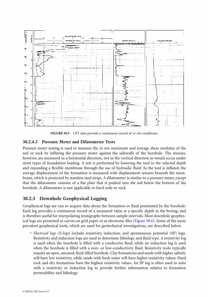
Because the CPT soundings provide continuous records of tip and sleeve resistances (and fre-quently pore pressure) vs. depth (Figure 30.3), they provide a continuous indicator of soil andsubsurface conditions that are useful in defining soil stratification. Numerous correlations betweenthe CPT measurements have been developed to define soil type and soil classification. In addition,empirical correlations have been published to relate the cone tip and sleeve friction resistances toengineering behavior, including undrained shear strength of clay soils and relative density andfriction of granular soils.
Most land CPTs are performed as continuous soundings using large 20-ton cone trucks(Figure 30.4a), although smaller, more portable track-mounted equipment is also available. CPTsoundings are commonly extended down to more than 20 to 50 m. CPT soundings also can beperformed over water from a vessel using specialized equipment (Figure 30.4b) deployed by a craneor from a stern A-frame. In addition, downhole systems have been developed to conduct CPTs inboreholes during offshore site investigations. With a downhole system, CPT tests are interspersedwith soil sampling to obtain CPT data to more than 100 m in depth.
30.2.4.2 In Situ Vane Shear TestsThe undrained shear strength of clay soils can be measured in situ using a vane shear test. This testis conducted by measuring the torque required to rotate a vane of known dimensions. The test canbe conducted from the ground surface by attaching a vane blade onto a rod or downhole below thebottom of a borehole with a drop-in remote vane (Figure 30.5). The downhole vane is preferable,since the torque required to rotate the active rotating vane is not affected by the torque of the rod.The downhole vane is used both for land borings and over-water borings.
FIGURE 30.2 CPT cones.
© 2000 by CRC Press LLC
30.2.4.3 Pressure Meter and Dilatometer TestsPressure meter testing is used to measure the in situ maximum and average shear modulus of thesoil or rock by inflating the pressure meter against the sidewalls of the borehole. The stresses,however, are measured in a horizontal direction, not in the vertical direction as would occur undermost types of foundation loading. A test is performed by lowering the tool to the selected depthand expanding a flexible membrane through the use of hydraulic fluid. As the tool is inflated, theaverage displacement of the formation is measured with displacement sensors beneath the mem-brane, which is protected by stainless steel strips. A dilatometer is similar to a pressure meter, exceptthat the dilatometer consists of a flat plate that is pushed into the soil below the bottom of theborehole. A dilatometer is not applicable to hard soils or rock.
30.2.5 Downhole Geophysical Logging
Geophysical logs are run to acquire data about the formation or fluid penetrated by the borehole.Each log provides a continuous record of a measured value at a specific depth in the boring, andis therefore useful for interpolating stratigraphy between sample intervals. Most downhole geophys-ical logs are presented as curves on grid paper or as electronic files (Figure 30.6). Some of the moreprevalent geophysical tools, which are used for geotechnical investigations, are described below.
• Electrical logs (E-logs) include resistivity, induction, and spontaneous potential (SP) logs.Resistivity and induction logs are used to determine lithology and fluid type. A resistivity logis used when the borehole is filled with a conductive fluid, while an induction log is usedwhen the borehole is filled with a non- or low-conductivity fluid. Resistivity tools typicallyrequire an open, uncased, fluid-filled borehole. Clay formations and sands with higher salinitywill have low resistivity, while sands with fresh water will have higher resistivity values. Hardrock and dry formations have the highest resistivity values. An SP log is often used in suitewith a resistivity or induction log to provide further information relative to formationpermeability and lithology.
FIGURE 30.3 CPT data provide a continuous record of in situ conditions.
© 2000 by CRC Press LLC

(a) On land; (b) over water.
© 2000 by CRC Press LLC
FIGURE 30.4 CPT sounding methods.

• Suspension (velocity) logs are used to measure the average primary, compression wave, andshear wave velocities of a 1-m-high segment of the soil and rock column surrounding theborehole. Those velocities are determined by measuring the elapsed time between arrivals ofa wave propagating upward through the soil/rock column. The suspension probe includesboth a shear wave source and a compression wave source, and two biaxial receivers that detectthe source waves. This technique requires an open, fluid-filled hole.
• Natural gamma logs measure the natural radioactive decay occurring in the formation to infersoil or rock lithology. In general, clay soils will exhibit higher gamma counts than granularsoils, although decomposed granitic sands are an exception to that generality. Gamma logscan be run in any salinity fluid as well as air, and also can be run in cased boreholes.
• Caliper logs are used to measure the diameter of a borehole to provide insight relative tocaving and swelling. An accurate determination of borehole diameter also is important forthe interpretation of other downhole logs.
• Acoustic televiewer and digital borehole logs are conducted in rock to image the rock surfacewithin the borehole (Figure 30.7). These logs use sound in an uncased borehole to create anoriented image of the borehole surface. These logs are useful for determining rock layering,bedding, and fracture identification and orientation.
• Crosshole, downhole, and uphole shear wave velocity measurements are used to determine theprimary and shear wave velocities either to determine the elastic soil properties of soil androck or to calibrate seismic survey measurements. With the crosshole technique, the traveltime is measured between a source in one borehole and a receiver in a second borehole. Thistechnique can be used to measure directly the velocities of various strata. For downhole anduphole logs, the travel time is measured between the ground surface and a downhole sourceor receiver. Tests are conducted with the downhole source or receiver at different depths.These measurements should preferably be conducted in cased boreholes.
FIGURE 30.5 In situ vane shear device.
© 2000 by CRC Press LLC

30.2.6 Test Pits and Trenches
Where near-surface conditions are variable or problematic, the results of borings and in situ testingcan be supplemented by backhoe-excavated or hand-excavated test pits or trenches. These tech-niques are particularly suitable for such purposes as: (1) collecting hand-cut, block samples ofsensitive soils; (2) evaluating the variability of heterogeneous soils; (3) evaluating the extent of fillor rubble, (4) determining depth to groundwater, and (5) the investigation of faulting.
30.2.7 Geophysical Survey Techniques
Noninvasive (compared with drilling methods) geophysical survey techniques are available forremote sensing of the subsurface. In contrast to drilling and in situ testing methods, the geophysicalsurvey methods explore large areas rapidly and economically. When integrated with boring data,these methods often are useful for extrapolating conditions between borings (Figure 30.8). Tech-niques are applicable either on land or below water. Some of the land techniques also are applicablefor marginal land or in the shallow marine transition zone. Geophysical survey techniques can beused individually or as a group.
FIGURE 30.6 Example of downhole geophysical log.
© 2000 by CRC Press LLC

FIGURE 30.7 Example of digital borehole image in rock.
FIGURE 30.8 Example integration of seismic reflection and boring data.
© 2000 by CRC Press LLC
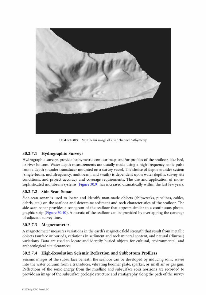
30.2.7.1 Hydrographic SurveysHydrographic surveys provide bathymetric contour maps and/or profiles of the seafloor, lake bed,or river bottom. Water depth measurements are usually made using a high-frequency sonic pulsefrom a depth sounder transducer mounted on a survey vessel. The choice of depth sounder system(single-beam, multifrequency, multibeam, and swath) is dependent upon water depths, survey siteconditions, and project accuracy and coverage requirements. The use and application of more-sophisticated multibeam systems (Figure 30.9) has increased dramatically within the last few years.
30.2.7.2 Side-Scan SonarSide-scan sonar is used to locate and identify man-made objects (shipwrecks, pipelines, cables,debris, etc.) on the seafloor and determine sediment and rock characteristics of the seafloor. Theside-scan sonar provides a sonogram of the seafloor that appears similar to a continuous photo-graphic strip (Figure 30.10). A mosaic of the seafloor can be provided by overlapping the coverageof adjacent survey lines.
30.2.7.3 MagnetometerA magnetometer measures variations in the earth’s magnetic field strength that result from metallicobjects (surface or buried), variations in sediment and rock mineral content, and natural (diurnal)variations. Data are used to locate and identify buried objects for cultural, environmental, andarchaeological site clearances.
30.2.7.4 High-Resolution Seismic Reflection and Subbottom ProfilersSeismic images of the subsurface beneath the seafloor can be developed by inducing sonic wavesinto the water column from a transducer, vibrating boomer plate, sparker, or small air or gas gun.Reflections of the sonic energy from the mudline and subsurface soils horizons are recorded toprovide an image of the subsurface geologic structure and stratigraphy along the path of the survey
FIGURE 30.9 Multibeam image of river channel bathymetry.
© 2000 by CRC Press LLC

vessel. The effective depth of a system and resolution of subsurface horizons depend on a numberof variables, including the system energy, output frequency spectrum, the nature of the seafloor,and the subsea sediments and rocks. Seismic reflection data are commonly used to determine thegeologic structure (stratigraphy, depth to bedrock, folds, faults, subsea landslides, gas in sediments,seafloor seeps, etc.) and evaluate the horizon continuity between borings (Figure 30.11).
30.2.7.5 Seismic RefractionSeismic refraction measurements are commonly used on land to estimate depth to bedrock andgroundwater and to detect bedrock faulting. Measured velocities are also used for estimates ofrippability and excavation characteristics. In the refraction technique, sonic energy is induced intothe ground and energy refracted from subsurface soil and rock horizons is identified at a series ofreceivers laid out on the ground. The time–distance curves from a series of profiles are inverted todetermine depths to various subsurface layers and the velocity of the layers. The data interpretationcan be compromised where soft layers underlie hard layers and where the horizons are too thin tobe detected by refraction arrivals at the surface. The technique also can be used in shallow water(surf zones, lakes, ponds, and river crossings) using bottom (bay) cables.
FIGURE 30.10 Side-scan sonar image of river bottom.
© 2000 by CRC Press LLC

30.2.7.6 Ground Penetrating Radar SystemsGround Penetrating Radar (GPR) systems measure the electromagnetic properties of the subsurfaceto locate buried utilities or rebar, estimate pavement thickness, interpret shallow subsurface stratig-raphy, locate voids, and delineate bedrock and landslide surfaces. GPR also can be used in arcticconditions to estimate ice thickness and locate permafrost. Depths of investigation are usuallylimited to 50 ft or less. Where the surface soils are highly conductive, the effective depth of inves-tigation may be limited to a few feet.
30.2.7.7 Resistivity SurveysResistivity surveys induce currents into the ground to locate buried objects and to investigate shallowgroundwater. As electrodes are moved in specific patterns of separation, the resistivity is measured
FIGURE 30.11 Interpreted stratigraphic relationships from seismic reflection data.
© 2000 by CRC Press LLC

and inverted to produce depth sections and contour maps of subsurface resistivity values. Thismethod is used to identify and map subsurface fluids, including groundwater, surface and buriedchemical plumes, and to predict corrosion potential.
30.2.8 Groundwater Measurement
Groundwater conditions have a profound effect on foundation design, construction, and perfor-mance. Thus, the measurement of groundwater depth (or depth of water when drilling over water)is one of the most fundamentally important elements of the site investigation. In addition to themeasurement of the water level, the site investigation should consider and define the potential forartesian or perched groundwater. It is also important to recognize that groundwater levels maychange with season, rainfall, or other temporal reasons. All groundwater and water depth measure-ments should document the time of measurement and, where practical, should determine variationsin depth over some period of elapsed time. To determine the long-term changes in water level, itis necessary to install and monitor piezometers or monitoring wells.
30.3 Defining Site Investigation Requirements
Many factors should be considered when defining the requirements (including types, numbers,locations, and depths of explorations) for the site investigation (Figure 30.12). These factors include:
• Importance, uncertainty, or risk associated with bridge design, construction, and performance
• Geologic conditions and their potential variability
• Availability (or unavailability) of historical subsurface data
• Availability (or unavailability) of performance observations from similar nearby projects
• Investigation budget
The following factors should be considered when evaluating the project risk: (1) What are the risks?(2) How likely are the risks to be realized? (3) What are the consequences if the risks occur? Risks include:
• Certainty or uncertainty of subsurface conditions;
• Design risks (e.g., possibility that inadequate subsurface data will compromise design deci-sions or schedule);
• Construction risks (e.g., potential for changed conditions claims and construction delays);
• Performance risks (e.g., seismic performance).
FIGURE 30.12 Key factors to consider when defining site investigation requirements.
© 2000 by CRC Press LLC

Two additional requirements that should be considered when planning a subsurface investigationare (1) reliability of the data collected and (2) timeliness of the data generated. Unfortunately, thesefactors are too often ignored or underappreciated during the site investigation planning process orgeotechnical consultant selection process. Because poor-quality or misleading subsurface data canlead to inappropriate selection of foundation locations, foundation types, and/or inadequate orinappropriate foundation capacities, selection of a project geotechnical consultant should be basedon qualifications rather than cost. Similarly, the value of the data generated from the subsurfaceinvestigation is reduced if adequate data are not available when the design decisions, which areaffected by subsurface conditions, are made. All too often, the execution of the subsurface explo-ration program is delayed, and major decisions relative to the general structure design and foun-dation locations have been cast in stone prior to the availability of the subsurface exploration results.
Frequently, the execution of the subsurface investigation is an iterative process that should beconducted in phases (i.e., desktop study, reconnaissance site investigation, detailed design-phaseinvestigation). During each phase of site exploration, it is appropriate for data to be reviewed asthey are generated so that appropriate modifications can be made as the investigation is ongoing.Appropriate adjustments in the investigation work scope can save significant expense, increase thequality and value of the investigation results, and/or reduce the potential for a remobilization ofequipment to fill in missing information.
30.3.1 Choice of Exploration Methods and Consideration of Local PracticeBecause many exploration techniques are suitable in some subsurface conditions, but not as suitableor economical in other conditions, the local practice for the methods of exploration vary from regionto region. Therefore, the approach to the field exploration program should consider and be tailored tothe local practice. Conversely, there are occasions where the requirements for a project may justify usingexploration techniques that are not common in the project area. The need to use special techniqueswill increase with the size of the project and the uniqueness or complexity of the site conditions.
30.3.2 Exploration DepthsThe depths to which subsurface exploration should be extended will depend on the structure, itssize, and the subsurface conditions at the project location. The subsurface exploration for any projectshould extend down through unsuitable layers into materials that are competent relative to thedesign loads to be applied by the bridge foundations. Some of the exploration should be deepenough to verify that unsuitable materials do not exist beneath the bearing strata on which thefoundations will be embedded. When the base of the foundation is underlain by layers of compress-ible material, the exploration should extend down through the compressible strata and into deeperstrata whose compressibility will not influence foundation performance.
For lightly loaded structures, it may be adequate to terminate the exploration when rock isencountered, provided that the regional geology indicates that unsuitable strata do not underlie therock surface. For heavily-loaded foundations or foundations bearing on rock, it is appropriate to verifythat the explorations indeed have encountered rock and not a boulder. It is similarly appropriate toextend at least some of the explorations through the weathered rock into sound or fresh rock.
30.3.3 Numbers of ExplorationsThe basic intent of the site investigation is to determine the subsurface stratigraphy and its variations,and to define the representative soil (or rock) properties of the strata together with their lateral andvertical variations. The locations and spacing of explorations should be adequate to provide areasonably accurate definition of the subsurface conditions, and should disclose the presence of anyimportant irregularities in the subsurface conditions. Thus, the numbers of explorations will dependon both the project size and the geologic and depositional variability of the site location. When sub-surface conditions are complex and variable, a greater number of more closely spaced explorations are
© 2000 by CRC Press LLC

warranted. Conversely, when subsurface conditions are relatively uniform, fewer and more widelyspaced explorations may be adequate.
30.3.4 The Risk of Inadequate Site CharacterizationWhen developing a site exploration program, it is often tempting to minimize the number ofexplorations or defer the use of specialized techniques due to their expense. The approach ofminimizing the investment in site characterization is fraught with risk. Costs saved by the executionof an inadequate site investigation, whether in terms of the numbers of explorations or the exclusionof applicable site investigation techniques, rarely reduce the project cost. Conversely, the cost savedby an inadequate investigation frequently increases the cost of construction by many times thesavings achieved during the site investigation.
30.4 Development of Laboratory Testing Program
30.4.1 Purpose of Testing Program
Laboratory tests are performed on samples for the following purposes:
• Classify soil samples;
• Evaluate basic index soil properties that are useful in evaluating the engineering propertiesof the soil samples;
• Measure the strength, compressibility, and hydraulic properties of the soils;
• Evaluate the suitability of on-site or borrow soils for use as fill;
• Define dynamic parameters for site response and soil–structure interaction analyses duringearthquakes;
• Identify unusual subsurface conditions (e.g., presence of corrosive conditions, carbonate soils,expansive soils, or potentially liquefiable soils).
The extent of laboratory testing is generally defined by the risks associated with the project.Soil classification, index property, and fill suitability tests generally can be performed on disturbed
samples, whereas tests to determine engineering properties of the soils should preferably be per-formed on relatively undisturbed, intact specimen. The quality of the data obtained from the latterseries of tests is significantly dependent on the magnitude of sample disturbance either duringsampling or during subsequent processing and transportation.
30.4.2 Types and Uses of Tests
30.4.2.1 Soil Classification and Index TestingSoil classification and index properties tests are generally performed for even low-risk projects. Engi-neering parameters often can be estimated from the available in situ data and basic index tests usingpublished correlations. Site-specific correlations of these basic values may allow the results of a fewrelatively expensive advanced tests to be extrapolated. Index tests and their uses include the following:
• Unit weight and water content tests to evaluate the natural unit weight and water content.
• Atterberg (liquid and plastic) limit tests on cohesive soils for classification and correlationstudies. Significant insight relative to strength and compressibility properties can be inferredfrom the natural water content and Atterberg limit test results.
• Sieve and hydrometer tests to define the grain size distribution of coarse- and fine-grainedsoils, respectively. Grain size data also are used for both classification and correlation studies.
Other index tests include tests for specific gravity, maximum and minimum density, expansionindex, and sand equivalent.
© 2000 by CRC Press LLC

30.4.2.2 Shear Strength TestsMost bridge design projects require characterization of the undrained shear strength of cohesivesoils and the drained strength of cohesionless soils. Strength determinations are necessary to evaluatethe bearing capacity of foundations and to estimate the loads imposed on earth-retaining structures.
Undrained shear strength of cohesive soils can be estimated (often in the field) with calibratedtools such as a torvane, pocket penetrometer, fall cone, or miniature vane shear device. Moredefinitive strength measurements are obtained in a laboratory by subjecting samples to triaxialcompression (TX), direct simple shear (DSS), or torsional shear (TS) tests. Triaxial shear tests(including unconsolidated-undrained, UU, tests and consolidated-undrained, CU, tests) are themost common type of strength test. In this type of test, the sample is subject to stresses that mimicin situ states of stress prior to being tested to failure in compression or shear. Large and more highrisk projects often warrant the performance of CU or DSS tests where samples are tested alongstress paths which model the in situ conditions. In contrast, only less-sophisticated UU tests maybe warranted for less important projects.
Drained strength parameters of cohesionless soils are generally measured in either relativelysimple direct shear (DS) tests or in more-sophisticated consolidated-drained (CD) triaxial tests. Ingeneral, few laboratory strength tests are performed on in situ specimens of cohesionless soil becauseof the relative difficulty in obtaining undisturbed specimens.
30.4.2.3 Compaction TestsCompaction tests are performed to evaluate the moisture–density relationship of potential fillmaterial. Once the relationship has been evaluated and the minimum level of compaction of fillmaterial to be used has been determined, strength tests may be performed on compacted specimensto evaluate design parameters for the project.
30.4.2.4 Subgrade ModulusR-value and CBR tests are performed to determine subgrade modulus and evaluate the pavementsupport characteristics of the in situ or fill soils.
30.4.2.5 Consolidation TestsConsolidation tests are commonly performed to (1) evaluate the compressibility of soil samples forthe calculation of foundation settlement; (2) investigate the stress history of the soils at the boringlocations to calculate settlement as well as to select stress paths to perform most advanced strengthtests; (3) evaluate elastic properties from measured bulk modulus values; and (4) evaluate the timerate of settlement. Consolidation test procedures also can be modified to evaluate if foundationsoils are susceptible to collapse or expansion, and to measure expansion pressures under variouslevels of confinement. Consolidation tests include incremental consolidation tests (which are per-formed at a number of discrete loads) and constant rate of strain (CRS) tests where load levels areconstantly increased or decreased. CRS tests can generally be performed relatively quickly andprovide a continuous stress–strain curve, but require more-sophisticated equipment.
30.4.2.6 Permeability TestsIn general, constant-head permeability tests are performed on relatively permeable cohesionlesssoils, while falling-head permeability tests are performed on relatively impermeable cohesive soils.Estimates of the permeability of cohesive soils also can be obtained from consolidation test data.
30.4.2.7 Dynamic TestsA number of tests are possible to evaluate the behavior of soils under dynamic loads such as waveor earthquake loads. Dynamic tests generally are strength tests with the sample subjected to somesort of cyclic loading. Tests can be performed to evaluate variations of strength, modulus, anddamping, with variations in rate and magnitude of cyclic stresses or strains. Small strain parametersfor earthquake loading cases can be evaluated from resonant column tests.
© 2000 by CRC Press LLC
For earthquake loading conditions, dynamic test data are often used to evaluate site response andsoil–structure interaction. Cyclic testing also can provide insight into the behavior of potentially lique-fiable soils, especially those which are not easily evaluated by empirical in situ test-based procedures.
30.4.2.8 Corrosion TestsCorrosion tests are performed to evaluate potential impacts on steel or concrete structures due tochemical attack. Tests to evaluate corrosion potential include resistivity, pH, sulfate content, andchloride content.
30.5 Data Presentation and Site Characterization
30.5.1 Site Characterization Report
The site characterization report should contain a presentation of the site data and an interpretationand analysis of the foundation conditions at the project site. The site characterization report should:
• Present the factual data generated during the site investigation;
• Describe the procedures and equipment used to obtain the factual data;
• Describe the subsurface stratigraphic relationships at the project site;
• Define the soil and rock properties that are relevant to the planning, design, construction,and performance of the project structures;
• Formulate the solutions to the design and construction of the project.
The site data presented in the site characterization report may be developed from the current and/orpast field investigations at or near the project site, as-built documents, maintenance records, andconstruction notes. When historic data are included or summarized, the original sources of the datashould be cited.
30.5.2 Factual Data Presentation
The project report should include the accurate and appropriate documentation of the factual datacollected and generated during the site investigation and testing program(s). The presentation andorganization of the factual data, by necessity, will depend upon the size and complexity of the projectand the types and extent of the subsurface data. Regardless of the project size or extent of exploration,all reports should include an accurate plan of exploration that includes appropriate graphicalportrayal of surface features and ground surface elevation in the project area.
The boring log (Figure 30.13) is one of the most fundamental components of the data documen-tation. Although many styles of presentation are used, there are several basic elements that generallyshould be included on a boring log. Those typical components include:
• Documentation of location and ground surface elevation;
• Documentation of sampling and coring depths, types, and lengths — e.g., sample type, blowcount (for driven samples), and sample length for soil samples; core run, recovery, and RQDfor rock cores — as well as in situ test depths and lengths;
• Depths and elevations of groundwater and/or seepage encountered;
• Graphical representation of soil and rock lithology;
• Description of soil and rock types, characteristics, consistency/density, or hardness;
• Tabular or graphical representation of test data.
In addition to the boring logs, the factual data should include tabulated summaries of test types,depths, and results together with the appropriate graphical output of the tests conducted.
© 2000 by CRC Press LLC
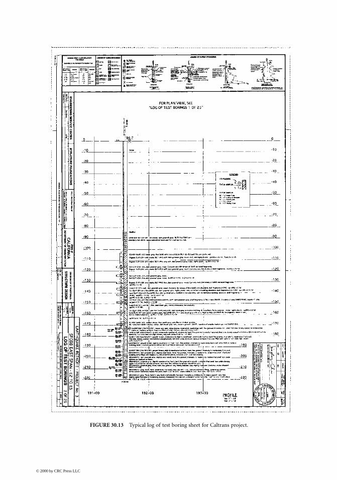
FIGURE 30.13 Typical log of test boring sheet for Caltrans project.
© 2000 by CRC Press LLC

30.5.3 Description of Subsurface Conditions and Stratigraphy
A sound geologic interpretation of the exploration and testing data are required for any project toassess the subsurface conditions. The description of the subsurface conditions should provide usersof the report with an understanding of the conditions, their possible variability, and the significanceof the conditions relative to the project. The information should be presented in a useful formatand terminology appropriate for the users, who usually will include design engineers and contractorswho are not earth science professionals.
To achieve those objectives, the site characterization report should include descriptions of
1. Site topography and/or bathymetry,2. Site geology,3. Subsurface stratigraphy and stratigraphic relationships,4. Continuity or lack of continuity of the various subsurface strata,5. Groundwater depths and conditions, and6. Assessment of the documented and possible undocumented variability of the subsurface
conditions.
Information relative to the subsurface conditions is usually provided in text, cross sections, andmaps. Subsurface cross sections, or profiles, are commonly used to illustrate the stratigraphicsequence, subsurface strata and their relationships, geologic structure, and other subsurface featuresacross a site. The cross section can range from simple line drawings to complex illustrations thatinclude boring logs and plotted test data (Figure 30.14).
Maps are commonly used to illustrate and define the subsurface conditions at a site. The mapscan include topographic and bathymetric contour maps, maps of the structural contours of astratigraphic surface, groundwater depth or elevation maps, isopach thickness maps of an indi-vidual stratum (or sequence of strata), and interpreted maps of geologic features (e.g., faulting,bedrock outcrops, etc.). The locations of explorations should generally be included on the inter-pretive maps.
The interpretive report also should describe data relative to the depths and elevations of ground-water and/or seepage encountered in the field. The potential types of groundwater surface(s) andpossible seasonal fluctuation of groundwater should be described. The description of the subsurfaceconditions also should discuss how the groundwater conditions can affect construction.
30.5.4 Definition of Soil Properties
Soil properties generally should be interpreted in terms of stratigraphic units or geologic deposits.The interpretation of representative soil properties for design should consider lateral and verticalvariability of the different soil deposits. Representative soil properties should consider the potentialfor possible in situ variations that have not been disclosed by the exploration program and laboratorytesting. For large or variable sites, it should be recognized that global averages of a particular soilproperty may not appropriately represent the representative value at all locations. For that condition,use of average soil properties may lead to unconservative design.
Soil properties and design recommendations are usually presented with a combination of narra-tive text, graphs, and data presented in tabular and/or bulleted list format. It is often convenientand helpful to reference generalized subsurface profiles and boring logs in those discussions. Thenarrative descriptions should include such factors as depth range, general consistency or density,plasticity or grain size, occurrence of groundwater, occurrence of layers or seams, degree of weath-ering, and structure. For each stratigraphic unit, ranges of typical measured field and laboratorydata (e.g., strength, index parameters, and blow counts) should be described.
© 2000 by CRC Press LLC

t Span alignment.
FIGURE 30.14 Subsurface cross section for San Francisco–Oakland Bay Bridge Eas© 2000 by CRC Press LLC

30.5.5 Geotechnical Recommendations
The site characterization report should provide solutions to the geotechnical issues and containgeotechnical recommendations that are complete, concise, and definitive. The recommended foun-dation and geotechnical systems should be cost-effective, performance-proven, and constructible.Where appropriate, alternative foundation types should be discussed and evaluated. When con-struction problems are anticipated, solutions to these problems should be described.
In addition to the standard consideration of axial and lateral foundation capacity, load–deflectioncharacteristics, settlement, slope stability, and earth pressures, there are a number of subsurfaceconditions that can affect foundation design and performance:
• Liquefaction susceptibility of loose, granular soils;
• Expansive or collapsible soils;
• Mica-rich and carbonate soils;
• Corrosive soils;
• Permafrost or frozen soils;
• Perched or artesian groundwater.
When any of those conditions are present, they should be described and evaluated.
30.5.6 Application of Computerized Databases
Computerized databases provide the opportunity to compile, organize, integrate, and analyze geo-technical data efficiently. All collected data are thereby stored, in a standard format, in a centralaccessible location. Use of a computerized database has a number of advantages. Use of automatedinteractive routines allows the efficient production of boring logs, cross sections, maps, and param-eter plots. Large volumes of data from multiple sources can be integrated and queried to evaluateor show trends and variability. New data from subsequent phases of study can be easily and rapidlyincorporated into the existing database to update and revise the geologic model of the site.
© 2000 by CRC Press LLC