ch 1. computer networks and the internet myungchul kim [email protected]
TRANSCRIPT


2
What is the Internet?
One sentence definition? – A nuts-and-bolts description– A service description
A nuts-and-bolts description– Hosts or end systems– A network of communication links and packet switches– Transmission rate– Packets– Packet switches: routers and link-layer switches– Route or path– Internet Service Providers (ISPs)– Protocols: TCP and IP– Internet Standards: Request for comments (RFCs) by IETF– Intranet
3
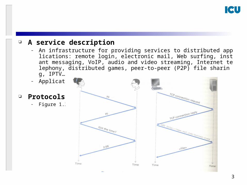
A service description– An infrastructure for providing services to distributed applications: remote login, e
lectronic mail, Web surfing, instant messaging, VoIP, audio and video streaming, Internet telephony, distributed games, peer-to-peer (P2P) file sharing, IPTV…
– Application Programming Interface (API)
Protocols– Figure 1.2.

4
Definition of a Protocol– Defines the format and the order of messages exchanged betwe
en two or more communicating entities, as well as the actions taken on the transmission and/or receipt of a message or other event
– Similar to a human analogy: there are specific messages we send, and specific actions we take in response to the received reply messages or other events

5
The Network Edge
Host = end system: clients and servers Peer-to-peer: acts as both a client and a server Access networks: connect an end system to its edge
router– Residential access– Company access– Wireless access
Residential access– Digital subscriber line (DSL): point-to-point– Hybrid fiber-coaxial cable (HFC): cable modems, shared– Very-high speed DSL (VDSL)

6
Company access– Ethernet : shared
Wireless access– Wireless LAN– IEEE 802.11 WiFi– 3G Wireless: HSDPA (High-Speed Downlink Packet Access)– IEEE 802.16 WiMax– WiBro
Physical media– Twisted-pair copper wire– Coaxial cable– Fiber optics– Terretrial radio channels: wireless LAN, the cellular access– Satellite Radio channels

7
The Network Core
Circuit switching– Reserved for the communication session– A circuit: at the guaranteed constant rate– Telephone network
Packet switching– The network resources on demand– Internet– Best effort
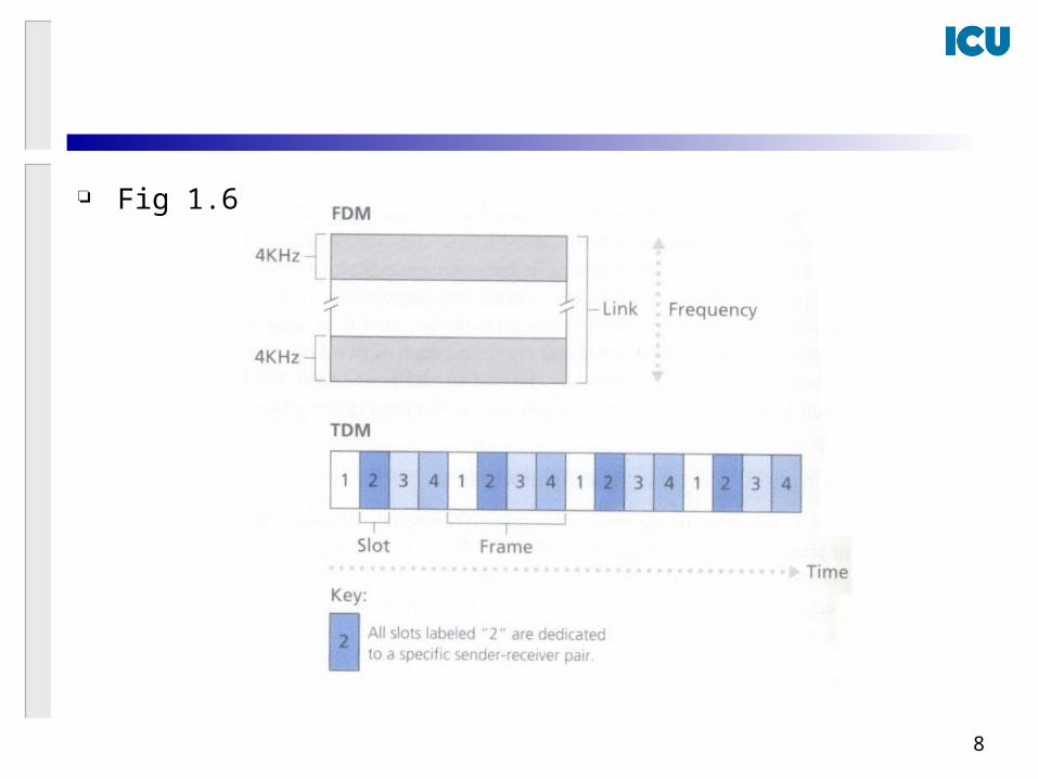
Multiplexing in Circuit-switched networks – The dedicated circuits are idle during silent periods– Frequency-division multiplexing (FDM) or Time-division
multiplexing (TDM)
8
Fig 1.6.
9
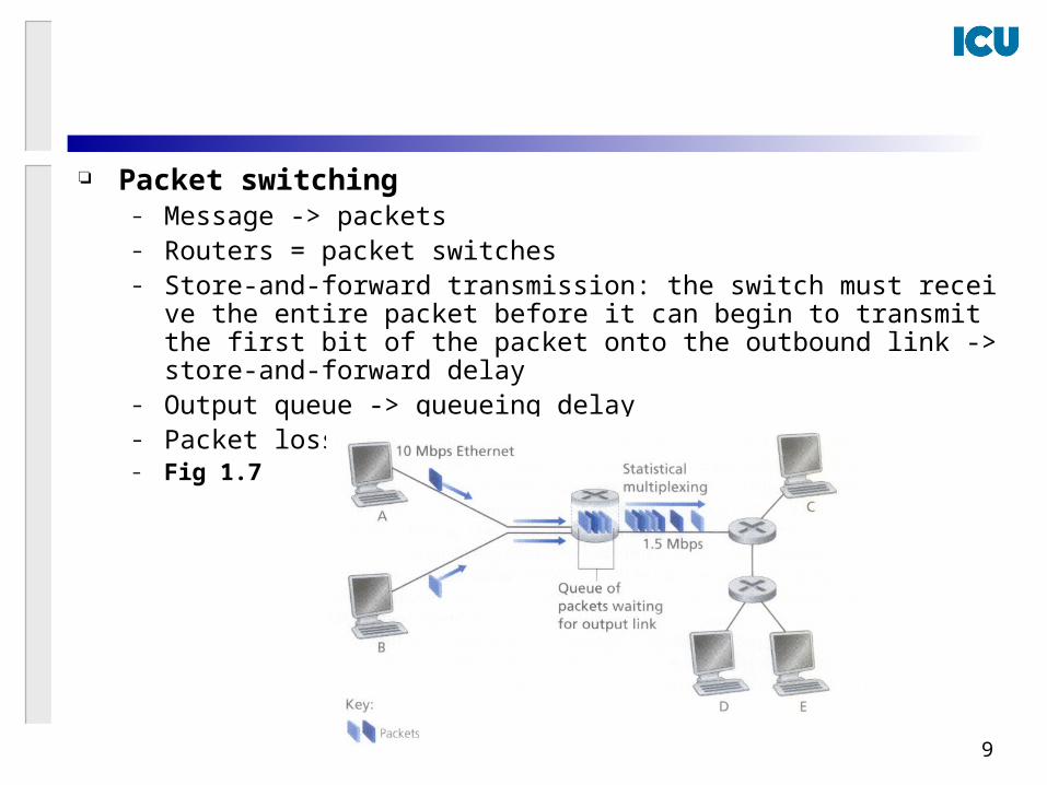
Packet switching– Message -> packets– Routers = packet switches– Store-and-forward transmission: the switch must receive the entire pack
et before it can begin to transmit the first bit of the packet onto the outbound link -> store-and-forward delay
– Output queue -> queueing delay– Packet loss– Fig 1.7
10
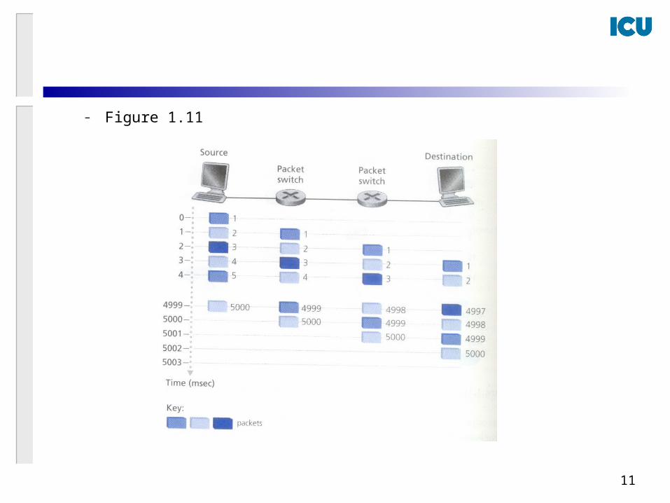
Packet switching vs Circuit switching
– Packet switching is not suitable for real-time services?
– Sharing of network resources -> statistical multiplexing of resour
ces
11
– Figure 1.11

12
ISPs and Internet Backbones
Tier-1 ISPs: Internet Backbone Tier-2 ISPs: regional or national coverage Access ISPs Points of Presence (POPs): the points at which the ISP conne
cts to other ISPs

13
Delay and loss in Packet-switched networks
Fig 1.18
Processing delay – Examine the packet’s header and determine where to direct the packet– Check for bit-level errors– Microseconds or less
Queuing delay– A packet waits to be transmitted onto the link– Depends on the number of earlier-arriving packets that are queued and
waiting for transmission across the link.– congestion– Microseconds to milliseconds.

14
Transmission delay– Store-and-forward delay– Transmit all of the packet’s bits into the link– L/R where L bits = length of the packet, R = 10 Mbps for a 10 Mbps Ether
net link– Microseconds to milliseconds
Propagation delay– Propagation speed of the link– d/s where d = distance and s = the propagation speed of the link– Milliseconds
Comparing transmission and propagation delay – d nodal = d proc + d queue + d trans + d prop
– d prop : hundreds of milliseconds for two routers by a satellite link
– d trans : hundreds of milliseconds for low-speed dial-up modem links– d proc : at the max rate of a router

15
Queuing delay – Traffic intensity La/R where a = the average rate of packets arrival at th
e queue (packets/sec), L bits of a packet, R = the transmission rate (bits/sec), and the infinite queue.
– If La/R > 1, the queue will tend to increase without bound and the queuing delay will approach infinity.
– If La/R ≤ 1, the nature of the arriving traffic impacts the queuing delay. Periodically or in bursts or random
– Fig 1.19

16
Packet loss – A queue has finite capacity.– Performance of a node = delay + packet loss
End-to-end delay – d end-end = N (d proc + d trans + d prop) for N-1 routers where
the network is uncongested.

17
Traceroute – Repeats experiment three times to get the round-trip delays between so
uce and destination– The queuing delay is varying with time. -> the round-trip delays are varyi
ng.– (Next slide)
Other delays– Media accessing delays in WiFi, Ethernet, …– Packetization delays in VoIP

18
“Real” Internet delays and routes
1 cs-gw (128.119.240.254) 1 ms 1 ms 2 ms2 border1-rt-fa5-1-0.gw.umass.edu (128.119.3.145) 1 ms 1 ms 2 ms3 cht-vbns.gw.umass.edu (128.119.3.130) 6 ms 5 ms 5 ms4 jn1-at1-0-0-19.wor.vbns.net (204.147.132.129) 16 ms 11 ms 13 ms 5 jn1-so7-0-0-0.wae.vbns.net (204.147.136.136) 21 ms 18 ms 18 ms 6 abilene-vbns.abilene.ucaid.edu (198.32.11.9) 22 ms 18 ms 22 ms7 nycm-wash.abilene.ucaid.edu (198.32.8.46) 22 ms 22 ms 22 ms8 62.40.103.253 (62.40.103.253) 104 ms 109 ms 106 ms9 de2-1.de1.de.geant.net (62.40.96.129) 109 ms 102 ms 104 ms10 de.fr1.fr.geant.net (62.40.96.50) 113 ms 121 ms 114 ms11 renater-gw.fr1.fr.geant.net (62.40.103.54) 112 ms 114 ms 112 ms12 nio-n2.cssi.renater.fr (193.51.206.13) 111 ms 114 ms 116 ms13 nice.cssi.renater.fr (195.220.98.102) 123 ms 125 ms 124 ms14 r3t2-nice.cssi.renater.fr (195.220.98.110) 126 ms 126 ms 124 ms15 eurecom-valbonne.r3t2.ft.net (193.48.50.54) 135 ms 128 ms 133 ms16 194.214.211.25 (194.214.211.25) 126 ms 128 ms 126 ms17 * * *18 * * *19 fantasia.eurecom.fr (193.55.113.142) 132 ms 128 ms 136 ms
traceroute: gaia.cs.umass.edu to www.eurecom.frThree delay measurements from gaia.cs.umass.edu to cs-gw.cs.umass.edu
* means no response (probe lost, router not replying)
trans-oceaniclink

19
Throughput
throughput: rate (bits/time unit) at which bits transferred between sender/receiver
– instantaneous: rate at given point in time– average: rate over long(er) period of time
server, withfile of F bits
to send to client
link capacity
Rs bits/sec
link capacity
Rc bits/sec pipe that can carry
fluid at rate
Rs bits/sec)
pipe that can carryfluid at rate
Rc bits/sec)
server sends bits
(fluid) into pipe

20
Throughput (more)
Rs < Rc What is average end-end throughput?
Rs bits/sec Rc bits/sec
Rs > Rc What is average end-end throughput?
Rs bits/sec Rc bits/sec
link on end-end path that constrains end-end throughput
bottleneck link

21
Protocol layers and their service models
A layered architecture allows us to discuss a well-defined, specific part of a large and complex system.
Protocol stack Service model
– Layer (n-1) is said to offer services to layer (n)
22
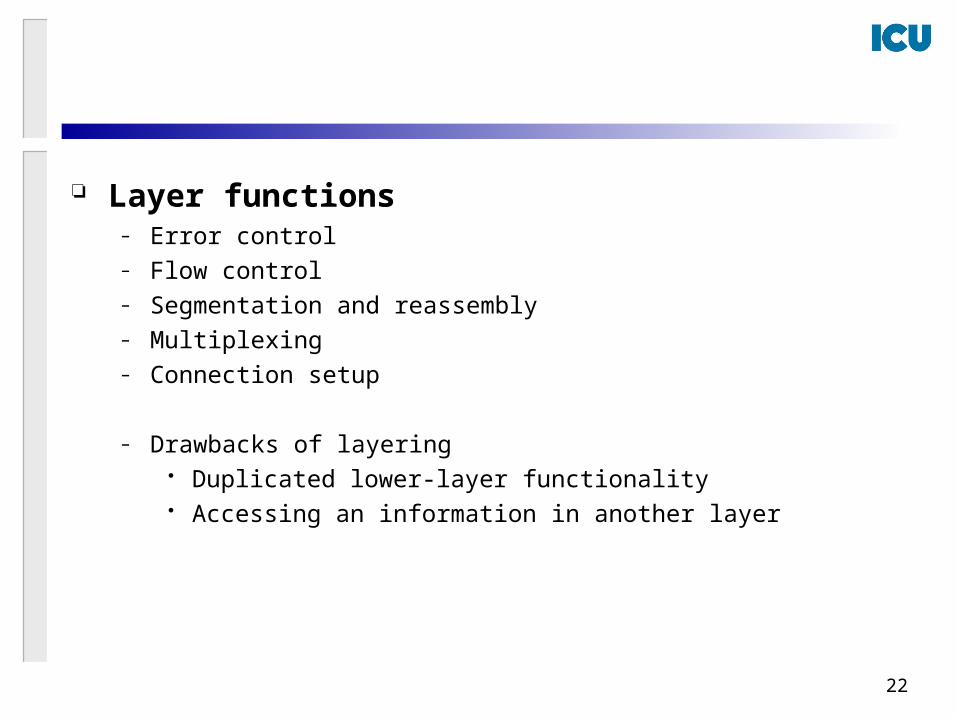
Layer functions – Error control– Flow control– Segmentation and reassembly– Multiplexing– Connection setup
– Drawbacks of layering Duplicated lower-layer functionality Accessing an information in another layer
23
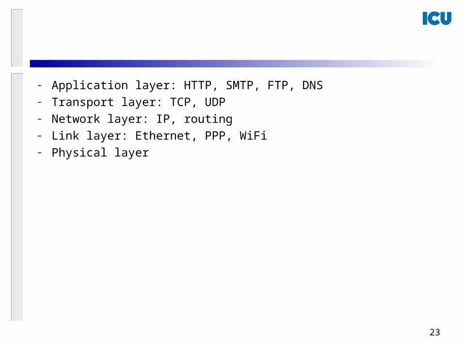
– Application layer: HTTP, SMTP, FTP, DNS– Transport layer: TCP, UDP– Network layer: IP, routing– Link layer: Ethernet, PPP, WiFi– Physical layer

24
The internet protocol stack

25
sourceapplicatio
ntransportnetwork
linkphysical
HtHn M
segment Ht
datagram
destination
application
transportnetwork
linkphysical
HtHnHl M
HtHn M
Ht M
M
networklink
physical
linkphysical
HtHnHl M
HtHn M
HtHn M
HtHnHl M
router
switch
Encapsulationmessage M
Ht M
Hn
frame

26
Networks under attack
Network security The bad guys can put malware into your host via the Internet
– Botnet, Self-replicating, Viruses, Worms, Trojan hoars The bad guys can attack servers and network infrastructure
– Denial-of-service (DoS) attacks, Distributed DoS attacks The bad guys can sniff packets
– A packet sniffer: Ethereal The bad guys can masquerade as someone you trust
– IP spoofing: with a false source address– Authentication
The bad guys can modify or delete messages– Man-in-the-middle attacks– Integrity of the data