ch-03
TRANSCRIPT
Introduction
To perform satisfactorily, shallow foundations must have two main characteristics:
1. They have to be safe against overall shear failure in the soil that supports them.2. They cannot undergo excessive displacement, or settleul1ent. (The term exces
sive is relative, because the degree of settlement allowed for a structure dependson several considerations.)
The load per unit area of the foundation at which shear failure in soil occurs is calledthe ultimate bearing capacity, which is the subject of this chaftter.
General Concept
Consider a strip foundation with a width of B resting on the surface of a dense sandor stiff cohesive soil, as shown in Figure 3.1a. Now, if a load is gradually applied tothe foundation, settlement will increase. The variation of the load per unit area, withthe foundation settlement on the foundation q, is also sho~ln in Figure 3.1a. At acertain point-when the load per unit area equals qu-a suclden failure in the soilsupporting the foundation will take place, and the failure surface in the soil willextend to the ground surface. This load per unit area, qu' is uS1uaily referred to as theultimate bearing capacity of the foundation. When such sudden failure in soil takesplace, it is called general shear failure.
If the foundation under consideration rests on sand or clayey soil of mediumcompaction (Figure 3.1b), an increase in the load on the foulldation will also be accompanied by an increase in settlement. However, in this case the failure surface inthe soil will gradually extend outward from the foundation, as shown by the solidlines in Figure 3.1b. When the load per unit area on the f()undation equals qu(l)'movement of the foundation will be accompanied by sudden jerks. A considerablemovement of the foundation is then required for the failure slLlrface in soil to extendto the ground surface (as shown by the broken lines in the figure). The load per unitarea at which tllis happens is the ultimate bearing capacity, quo Beyond that point, anincrease in load will be accompanied by a large increase in foundation settlement.
123

124 Chapter 3 Shallow Foundations: Ultimate Bearing Capacity
B Load/unit area, q
(a)
B
(b)
Failuresurfacein soil
Failuresurface
Settlement
Settlement
Load/unit area, q
B Load/unit area, q
..~;;.:.::.:::.'.:..;: :;.:::::.'.: :;.:..: =..::.!.=:::.::::.•;•..•.=..:: :._:.::.~;: : : ::.::..~;._:.: ~..: ' : :..:.:..: :..=:..:.......... ..••.: :=.~~:.: ":: ..:.~ ..~. ::.::.~:.::: :".:: ::.:.;."::":""-:.:::".=-- ;:.:..:~ ;:;:.::::~.:: ...~.~.: ~·::~):f::~::·.:~·: ...:~·!::::.::::::..~·~~~:.;:
Failuresurface
(c)
Surfacefooting
Settlement
Figure 3. 1 Nature of bearing capacity failure in soil: (a) general shear failure: (b) localshear failure; (c) punching shear failure (redrawn after Vesic, 1973)
The load per unit area of the foundation, qu(l)' is referred to as the first failure load(Vesic, 1963). Note that a peak value of q is not realized in this type of failure, whichis called the local shear failure in soiL
If the foundation is supported by a fairly loose soil, the load-settlement plot willbe like the o.ne in Figure 3.1c. In this case, the failure surface in soil will not extend to theground surface. Beyol1d the ultimate failure load, qu' the load-settlenlent plot will besteep and practically linear.This type of failure in soil is called the punching shear failure.
Vesic (1963) conducted several laboratory load-bearing tests on circular andrectangular plates supported by a sand at various relative densities of compaction,Dr- The variations of QU(1)/hB and qulhB obtained from those tests, where B is thediameter of a circular plate or width of a rectangular plate and y is a dry unit weight
:··'1"·.:~f.:,""
·1.."'.:.·.·)t

3.2 General Concept 125
0.2 0.3 0.4
Relative density Dr
0.5 0.6 0.7 0.8 0.9I I I I I I
PunchingLocal shear
Generalshear shear
/OJr
j/.'t)1-
.~.;iI
1/oj
0 • d"./ /
"/ tf/ .P
qu / " /'-- / /e1
-7 //() . /
/
~v / LegendD A.
/ • • Circular plate 203 mm (8 in.)~ / D 0 Circular plate 152 mm (6 in.)
])'/qu 1) • • Circular plate 102 mn1 (4 in.)- o 0 Circular plate 51 mm (2 in.)/: 1)B2 ~ 6. Rectangular plate 51 x 305 mm
(2 x 12 in.)Reduced by 0.6Small signs indicate first failure load
I I I
700
600
500
400
300
200
~I ~~ ,...-4IN
'"0 100qro
9031 ~ 80~ ,...-4IN 70
6050
40
30
20
101.32 1.35 1.40 1.45 1.50 1.55 1.60
Dry unit weight, Yd
Unit weight of water, yw
Figure 3.2 Variation of qU(1)/O.5yB and Qu/O.5yB for circular and rectangular plates on thesurface of a sand (adapted from Vesic,.1963)
of sand, are shown in Figure 3.2. It is important to note from this figure that, for Dr ~about 700/0, the general shear type of failure in soil occurs.
On the basis of experimental results, Vesic (1973) proposed a relationship forthe mode of bearing capacity failure of foundations resting on sands. Figure 3.3shows this relationship, which involves the notation
Dr == relative density of sand
Df == depth of foundation measured from the ground surface
B* = 2BLB + L (3.1)

126 Chapter 3 Shallow Foundations: Ultimate Bearing Capacity
Figure 3.3 Modes offoundation failure in sand(after Vesic, 1973)
J3
4
5~--.........._----"'---""-------'------..
1
Punching shearfailure
2b
~............
0......
3
Relative density, Dr
0.2 0.4 0.6 0.8 1.0or------.------.,..-..---..---..---.------.
where B == width of foundationL == length of foundation
(Note: L is alway·s greater than B.)For square foundations, B == L; for circular foundations, B == L == diameter, so
B* == B (3.2)
Figure 3.4 shows the settlement S of the circular and rectangular plates on the surfaceof a sand at ultinlate load, as described in Figure 3.2. The figure indicates a generalrange of S/ B with the relative density of con1paction of sand. So, in general, we can saythat, for foundatic)ns at a shallow depth (i.e., small Dr/B*), the ultimate load may occurat a foundation settlement of 4-10 ok> of B. This condition arises together with generalshear failure in soil; however, in the case of local or punching shear failure, the ultimateload may occur at settlements of 15-25% of the width of the foundation (B).
Terzaghi's Bearing Capacity Theory
Terzaghi (1943) vvas the first to present a comprehensive theory for the evaluationof the ultimate bearing capacity of rough shallow foundations. According to this theory, a foundation is shallow if its depth, Dr (Figure 3.5), is less than or equal to itswidth. Later investigators, however, have suggested that foundations with Df equalto 3-4 times their width may be defined as shallow foundations.
Terzaghi suggested that for a continuous, or strip, foundation (i.e., one whosewidth-to-length ratio approaches zero), the failure surface in soil at ultimate loadmay be assumed to be similar to that shown in Figure 3.5. (Note that this is the caseof general shear failure, as defined in Figure 3.1a.) The effect of soil above the bottom

3.3 Terzaghi's Bearing Capacity Theory 127
0.2 0.3 0.4
Relative density Dr0.5 0.6 0.7 0.8
I I
Punchingshear
J I ILocal shear
I
Generalshear
25% I------..,..----I-----r------,-------,-..a....-----r---t
SB
1----------f-. _.-",~20% 1--------I--------t----O=--~I'~--I··~~.-;;:---V\~-----t----1
...'" ~ectangular'" plate
Circular plates "
Circular plate diameter (B)
• 203 mm (8 in.)
o 152 mm (6 in.)
5% - • 102 mm (4 in.)
o 51 mm (2 in.)
~ 51 x 305 mm (2 x 12 in.)Rectangular plate (width == B)
0% L...-__---L.1 .o....-1 ----'- .........I.o ............----I
1.35 1.40 1.45 1.50 1.55
Dry unit weight, Yd
Unit weight of water, yw
Figure 3.4 Range of settlement of circular and rectangular plates at ultimate load(Dt / B = 0) in sand (modified from Vesic, 1963)
I]
E SoilUnit weight = ~
Cohesion = c'Friction angle = cP'
Figure 3.5 Bearing capacity failure in soil under a rough rigid continuous foundation

128 Chapter 3 Shallow Foundations: Ultimate Bearing Capacity
of the foundation may also be assumed to be replaced by an equivalent surcharge,q == yDf (where y is a unit weight of soil). The failure zone under the foundation canbe separated into three parts (see Figure 3.5):
1. The triangular zone ACD immediately under the foundation2. The radial shear zones ADF and CD E, with the curves DE and D F being arcs of
a logarithmic spiral3. Two triangular Rankine passive zones AFH and CEG
The angles CAD and ACD are assumed to be equal to the soil friction angle f/J'.Note that, with the replacement of the soil above the bottom of the foundation byan equivalent surcharge q, the shear resistance of the soil along the failure surfacesGI and HI was neglected.
Using equilibrium analysis, Terzaghi expressed the ultimate bearing capacityin the form
(3.3)
where c' = cohesion of soily = unit weight of soilq == yDf
N C' N q' Ny == bearing capacity factors that are nondimensional and are functions only of the soil friction angle f/J'
The bearing capacity factors Nc' Nq, and Ny are defined by
I
I
and
[
e2(37J/4-q//2)tan q/ ]
Nc = cot¢' 2('1T <p') - 1 = cot <p'(Nq - 1)2 cos - +-
4 2
e2 (37J/4 - l/J'/2)tan l/J'
Nq
= ( <p')2cos2 45 + 2
(3.4)
(3.5)
I
I
(3.6)1( K py) ,Ny = -2 2 - 1 tan f/J
cos <p'
where Kp'Y == passive pressure coefficient
The variations of the bearing capacity factors defined by Eqs. (3.4), (3.5), and (3.6)are given in Table 3.1.
To estimate the ultimate bearing capacity of square and circular foundations,Eq. (3.1) may be respectively modified to
I
(3.7)
Ij
~.
3.3 Terzaghi's Bearing Capacity Theory 129
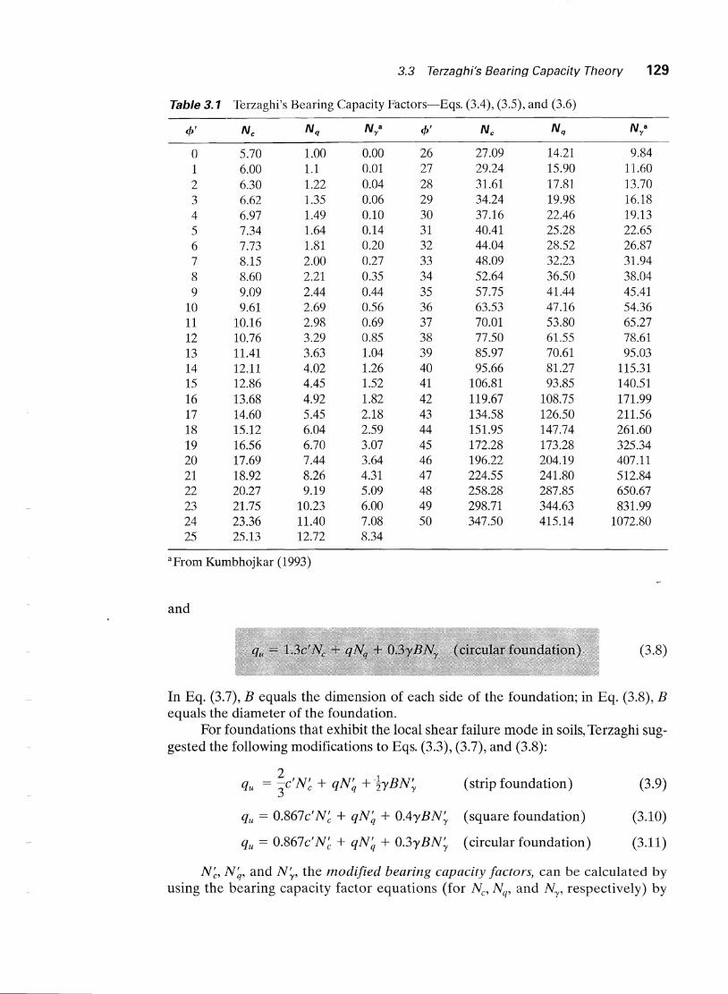
Table 3.1 Terzaghi's Bearing Capacity Factors-Eqs. (3.4), (3.5), and (3.6)
4>' Nc Nq Na l/J' N c Nq Na'Y y
0 5.70 1.00 0.00 26 27.09 14.21 9.841 6.00 1.1 0.01 27 29.24 15.90 11.602 6.30 1.22 0.04 28 31.61 17.81 13.703 6.62 1.35 0.06 29 34.24 19.98 16.184 6.97 1.49 0.10 30 37.16 22.46 19.135 7.34 1.64 0.14 31 40.41 25.28 22.656 7.73 1.81 0.20 32 44.04 28.52 26.877 8.15 2.00 0.27 33 48.09 32.23 31.948 8.60 2.21 0.35 34 52.64 36.50 38.049 9.09 2.44 0.44 35 57.75 41.44 45.41
10 9.61 2.69 0.56 36 63.53 47.16 54.3611 10.16 2.98 0.69 37 70.01 53.80 65.2712 10.76 3.29 0.85 38 77.50 61.55 78.6113 11.41 3.63 1.04 39 85.97 70.61 95.0314 12.11 4.02 1.26 40 95.66 81.27 115.3115 12.86 4.45 1.52 41 106.81 93.85 140.5116 13.68 4.92 1.82 42 119.67 108.75 171.9917 14.60 5.45 2.18 43 134.58 126.50 211.5618 15.12 6.04 2.59 44 151.95 147.74 261.6019 16.56 6.70 3.07 45 172.28 173.28 325.3420 17.69 7.44 3.64 46 196.22 204.19 407.1121 18.92 8.26 4.31 47 224.55 241.80 512.8422 20.27 9.19 5.09 48 258.28 287.85 650.6723 21.75 10.23 6.00 49 298.71 344.63 831.9924 23.36 11.40 7.08 50 347.50 415.14 1072.8025 25.13 12.72 8.34
aFraID Kumbhajkar (1993)
and
(3.8)
In Eq. (3.7), B equals the dinlension of each side of the foundation; in Eq. (3.8), Bequals the diameter of the foundation.
For foundations that exhibit the local shear failure mode in soils, Terzaghi sug-gested the following modifications to Eqs. (3.3), (3.7), and (3.8):
2qu == -c'N' + qN' + -lyBN' (strip foundation) (3.9)3 c q 2 'Y
qu == O.867c'N~ + qN~ + O.4yBN~ (square foundation) (3.10)
qu == 0.867c'N~ + qN~ + 0.3yBN~ (circular foundation) (3.11)
N~, N~, and N;, the modified bearing capacity factors, can be calculated byusing the bearing capacity factor equations (for Nc' Nq, and Ny, respectively) by

130 Chapter 3 Shallow Foundations: Ultimate Bearing Capacity
replacing cP' by ¢' == tan-l(~ tan 1>'). The variation of N~, N~, and N~ with the soilfriction angle cP is given in Table 3.2.
Terzaghi's bearing capacity equations have now been lllodified to take into account the effects of the foundation shape (ElL), depth of embedm-ent (Dt ), andthe load inclination. This is given in Section 3.7. Many design engineers, however,still use Terzaghi's equation, which provides fairly good results considering the uncertainty of the soil conditions at various sites.
Factor of Safety
Calculating the gross allowable load-bearing capacity of shallow foundations requires the application of a factor of safety (FS) to the gross ultimate bearing capacity, or
Table 3.2 Terzaghi's Modified Bearing Capacity Factors N~, N~, and N~
ep' N' N' N' 4>' N' N' N'c q Y c q Y
0 5.70 1.00 0.00 26 15.53 6.05 2.591 5.90 1.07 0.005 27 16.30 6.54 2.88 I2 6.10 1.14 0.02 28 17.13 7.07 3.293 6.30 1.22 0.04 29 18.03 7.66 3.764 6.51 1.30 0.055 30 18.99 8.31 4.395 6.74 1.39 0.074 31 20.03 9.03 4.836 6.97 1.49 0.10 32 21.16 9.82 5.517 7.22 1.59 0.128 33 22.39 10.69 6.328 7.47 1.70 0.16 34 23.72 11.67 7.229 7.74 1.82 0.20 35 25.18 12.75 8.35
10 8.02 1.94 0.24 36 26.77 13.97 9.4111 8.32 2.08 0.30 37 28.51 15.32 10.9012 8.63 2.22 0.35 38 30.43 16.85 12.7513 8.96 2.38 0.42 39 32.53 18.56 14.7114 9.31 2.55 0.48 40 ,34.87 20.50 17.2215 9.67 2.73 0.57 41 37.45 22.70 19.7516 10.06 2.92 0.67 42 40.33 25.21 22.5017 10.47 3.13 0.76 43 43.54 28.06 26.25 :118 10.90 3.36 0.88 44 47.13 31.34 30.40 'i' .
19 11.36 3.61 1.03 45 51.17 35.11 36.0020 11.85 3.88 1.12 46 55.73 39.48 41.7021 12.37 4.17 1.35 47 60.91 44.45 49.3022 12.92 4.48 1.55 48 66.80 50.46 59.2523 13.51 4.82 1.74 49 73.55 57.41 71.4524 14.14 5.20 1.97 50 81.31 65.60 85.7525 14.80 5.60 2.25

(3.13)
3.4 Factor of Safety 131
However, some practicing engineers prefer to use a factor of safety such that
. . net ultimate bearing capacityNet stress mcrease on sOlI = FS
The net ultimate bearing capacity is defined as the ultimate pressure per unit area ofthe foundation that can be supported by the soil in excess of the pressure caused by thesurrounding soil at the foundation level. If the difference between the unit weight ofconcrete used in the foundation and the unit weight of soil surrounding is assumed tobe negligible, then
(3.14)
where qnet(u) =: net ultimate bearing capacityq == yDf
So
qu - qqall(net) == FS
The factor of safety as defined by Eq. (3.15) should be at least 3 in all cases.
(3.15)

(3.16)
Modification of Bearing Capacity Equationsfor Water Table
Equations (3.3) and (3.7) through (3.11) give the ultimate bearing capacity, based onthe assumption that the water table is located well below the foundation. However,if the water table is close to the foundation, some modifications of the bearing capacity equations will be necessary. (See Figure 3.6.)
Case I. If the water table is located so that 0 ~ D1 ~ Df , the factor q in thebearing capacity equations takes the form
q = effective surcharge == DIY + D 2 ( Ysat - Yw)
where Ysat == saturated unit weight of soilYw == unit weight of water
132 Chapter 3 Shallow Foundations: Ultimate Bearing Capacity

3.6 Case History: Ultimate Bearing Capacity in Saturated Clay 133
d
___J .9E<:.uE~~a.!~Et.E~_~ -_ Case II
'Ysat = saturatedunit weight
Figure 3.6 Modificationof bearing capacity equations for water table
Also, the value of 'Y in the last term of the equations has to be replaced by y' ==
Ysat - Yw·
Case II. For a water table located so that 0 ~ d ~ B,
q == 'YDf (3.17)
In this case, the factor y in the last term of the bearing capacity equations must bereplaced by the factor
(3.18)
The preceding modifications are based on the assumption that there is no seepageforce in the soil.
Case III. When the water table is located so that d ~ B, the water will have noeffect on the ultimate bearing capacity.
Case History: Ultimate Bearing Capacityin Saturated Clay
Brand et al. (1972) reported field-test results of soil explorations on smallfoundations in soft Bangkok clay (a deposit of marine clay) in Rangsit, Thailand.The results are shown in Figure 3.7. Because of the sensitivity of the clay, the labo-ratory test results for Cu (unconfined compression and unconsolidated undrainedtriaxial) were rather scattered; however, better results were obtained for the

~
W~
Sensitivity
0 5 10 15I I
A Field vane& Unconfined compo
I&t ••-
~~I •
~ & I.
•~
MI A I A
A
~
\A
cu-UU Triaxial(kN/m2
)
20 30
cu-UnconfinedCompression (kN/m2
)
10 20 30 110
cu-Field Vane(kN/m2)
20 302110
LiquidityIndex
----.5L-
~ I I0
0
0
• OJ
rn •0 • • •
0 •• 0
• •o 00 o 0 - CD
- ••
CDO 0
o I -, I • I I I 0 leod
---0
0
80 1201040
ox
Moisture Content (%)
o
00
0
a00
0
8
x-!-x.•
•
~
SoilProfile
o
1~ PLLight gray, 0
iOftClay,'
2 weatheredto som~
3 ~~~,~~~~A-
4~Daik giay,
~t clay~
I-rf.*I~
Dark gray,'soft clay~
8 ':-:'::::::::::::;:::::::::::::::qLight gray, ox
)stiff clay}9'::::-:':::':':::';':;:':::;:':::::;:
8"-'..caiUQ
Figure 3.7 Results of soil exploration in soft B~ngkok clay at Rangsit, Thailand (redrawn after Brand et aI., 1972)
•
f;;.•...."':-
!:{~~i~'~~~;~~' • •• ;'''j\"

3.6 Case History: Ultimate Bearing Capacity in Saturated Clay 135
variation of Cu with depth from field vane shear tests, which showed that the average variations of the undrained cohesion were as follows:
Depth (m)
0-1.51.5-2
2-8
~35
Decreasing linearly from 35 to 24~24
Five small square foundations were tested for ultimate bearing capacity. Thesizes of the foundations were 0.6 m X 0.6 ill, 0.675 ill X 0.675 ill, 0.75 ill X 0.75 ill,
0.9 m X 0.9 ill, and 1.05 m X 1.05 ffi. The depth of the bottom of the foundationswas 1.5 m, measured from the ground surface. The load-settlement plots obtainedfrom the bearing capacity tests are shown in Figure 3.8.
Load (kN)
o 40 80 120 160 200O-r-----------.------r-----r--------,
• Qu (ultimate load)
10
30
40'--------.&.--------'----------------.......
Figure 3.8 Load-settlement plots obtained from bearing capacity tests
Analysis of the Field-Test Results
The ultimate loads, Qu, obtained from each test are also shown in Figure 3.8. Theultimate load is defined as the point where the load displacement becomes practically linear. The failure in soil below the foundation is of the local shear type.Hence, we may apply Eq. (3.10):
qu == 0.867cuN~ + qN~ + O.4'YBN~
For cb == 0, C == Cu and, from Table 3.2, N~ == 5.7, N~ == 1, and N~ == o. Thus, for4> = 0,
(3.19)
136 Chapter 3 Shallow Foundations: Ultimate Bearing Capacity
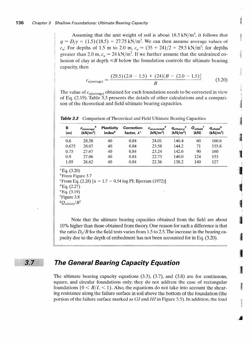
Assuming that the unit weight of soil is about 18.5 kN/m3, it follows that
q ~ DIY == (1.5) (18.5) == 27.75 kN/m2• We can then assume average values of
Cu: For depths of 1.5 ill to 2.0 ill, Cu ~ (35 + 24)/2 == 29.5 kN/m2; for depths
greater than 2.0 m, Cu ~ 24 kN/m2. If we further assume that the undrained co
hesion of clay at depth ~B below the foundation controls the ultimate bearingcapacity, then
Cu(average) ~
(29.5) (2.0 - 1.5) + (24)[B - (2.0 - 1.5)J
B(3.20)
The value of cu(average) obtained for each foundation needs to be corrected in vie,vof Eq. (2.19). Table 3.3 presents the details of other calculations and a comparison of the theoretical and field ultimate bearing capacities.
Table 3.3 Comparison of Theoretical and Field Ultimate Bearing Capacities
B Cu(average)a Plasticity Correction cu(corrected)
dqu(theory)
eQu(field)
fqu{field)
9
(m) (kN/m2) indexb factor, AC (kN/m2) (kN/m2) (kN) (kN/m2
)
0.6 28.58 40 0.84 24.01 146.4 60 166.60.675 28.07 40 0.84 23.58 144.2 71 155.80.75 27.67 40 0.84 23.24 142.6 90 1600.9 27.06 40 0.84 22.73 140.0 124 1531.05 26.62 40 0.84 22.36 138.2 140 127
aEq. (3.20)bprom Figure 3.7cFrom Eq. (2.28) [A == 1.7 - 0.54 log PI; Bjerrum (1972)]dEq. (2.27)CEq. (3.19)fFigure 3.8
g QU(field)/B2
Note that the ultimate bearing capacities obtained from the field are about10% higher than those obtained from theory. One reason for such a difference is thatthe ratio DtlB for the field tests varies from 1.5 to 2.5. The increase in the bearing capacity due to the depth of embedment has not been accounted for in Eq. (3.20).
The General Bearing Capacity Equation
The ultimate bearing capacity equations (3.3), (3.7), and (3.8) are for continuous,square, and circular foundations only; they do not address the case of rectangularfoundations (0 < BIL < 1). Also, the equations do not take into account the shearing resistance along the failure surface in soil above the bottom of the foundation (theportion of the failure surface marked as GI and HJ in Figure 3.5). In addition, the load
3.7 The General Bearing Capacity Equation 137
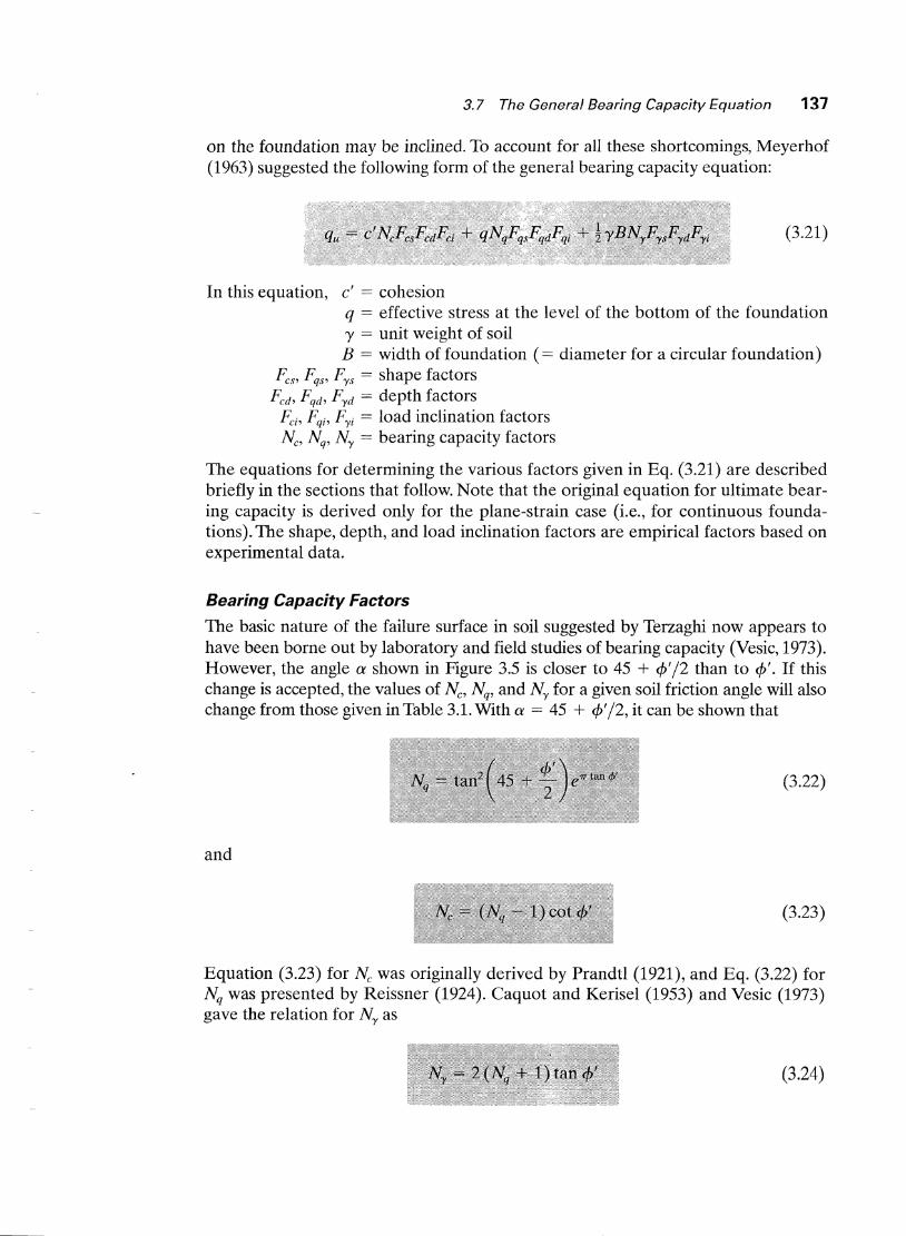
on the foundation may be inclined. To accou.nt for all these shortcomings, Meyerhof(1963) suggested the following form of the general bearing capacity equation:
(3.21)
In this equation, c' == cohesionq == effective stress at the level of the bottom of the foundationy == unit weight of soilB == width of foundation (== diameter for a circular foundation)
Fcs , Fqs , Fys == shape factorsFcd, Fqd , Fyd == depth factors
Fcf, Fqf, Fyi == load inclination factorsNc, Nq , Ny == bearing capacity factors
The equations for determining the various factors given in Eq. (3.21) are describedbriefly in the sections that follow. Note that the original equation for ultimate bearing capacity is derived only for the plane-strain case (i.e., for continuous foundations). The shape, depth, and load inclination factors are empirical factors based onexperimental data.
Bearing Capacity Factors
The basic nature of the failure surface in soil suggested by Terzaghi now appears tohave been borne out by laboratory and field studies of bearing capacity (Vesic, 1973).However, the angle a shown in Figure 3.5 is closer to 45 + </J'/2 than to </J'. If thischange is accepted, the values of Nc, Nq, and Ny for a given soil friction angle will alsochange from those given in Table 3.1. With a == 45 + </J'/2, it can be shown that
(3.22)
and
(3.23)
Equation (3.23) for Nc was originally derived by Prandtl (1921)~ and Eq. (3.22) forNq was presented by Reissner (1924). Caquot and Kerisel (1953) and Vesic (1973)gave the relation for Ny as
(3.24)

138 Chapter 3 Shallow Foundations: Ultimate Bearing Capacity
Table 3.4 shows the variation of the preceding bearing capacity factors with soil friction angles.
Shape Factors The equations for the shape factors Fes' Fq,p and Frs were reconlmended by De Beer (1970) and are
Fes = 1 + (~)(~~)
Fqs = 1 + (~)tan <P'
and
Frs = 1- O.4(~)
where L == length of the foundation (L > B)
Table 3.4 Bearing Capacity Factors
(3.25)
(3.26)
(3.27)
t/J'
o123456789
10111213141516171819202122232425
5.145.385.635.906.196.496.817.167.537.928.358.809.289.81
10.3710.9811.6312.3413.1013.9314.8315.8216.8818.0519.3220.72
1.001.091.201.311.431.571.721.882.062.252.472.712.973.263.593.944.344.775.265.806.407.077.828.669.60
10.66
0.000.070.150.240.340.450.570.710.861.031.221.441.691.972.292.653.063.534.074.685.396.207.138.209.44
10.88
t/J'
26272829303132333435363738394041424344454647484950
22.2523.9425.8027.8630.1432.673j~:l9
38.6442.1646.1250.5955.6361.3567.8775.3183.8693.71
105.11118.37133.88152.10173.64199.26229.93266.89
11.8513.2014.7216.4418.4020.6323.1826.0929.4433.3037.7542.9248.9355.9664.2073.9085.3899.02
115.31134.88158.51187.21222.31265.51319.07
12.5414.4716.7219.3422.4025.99~0.22
35.1941.0648.0356.3166.1978.0392.25
109.41130.22155.55186.54224.64271.76330.35403.67496.01613.16762.89
I

3.8 Meyerhof's Bearing Capacity, Shape, Depth, and Inclination Factors 139
The shape factors are empirical relations based on extensive laboratory tests.
D~epth Factors Hansen (1970) proposed the following equations for the depthfactors:
(3.28)
(3.29)
(3.30)
E,quations (3.28) and (3.29) are valid for Df / B ~ 1. For a depth-of-embedment-tof()undation-width ratio greater than unity (Dt / B > 1), the equations have to beIIlodified to
a][ld
Fed = 1 + (0.4) tan~l (~)
Fqd = 1 + 2 tan 4>'(1 - Sin4>,)2tan-l(i')(3.31)
(3.32)
Fyd == 1 (3.33)
respectively. The factor tan-1 (Dt / B) is in radians in Eqs. (3.31) and (3.32).
IIJclination Factors Meyerhof (1963) and Hanna and Meyerhof (1981) suggestedtIle following inclination factors for use in Eq. (3.21):
,.
(f30 )2
Fei = Fqi = 1 - 900 (3.34)
(3.35)
Here, {3 == inclination of the load on the foundation with respect to the vertical.
Meyerhof's Bearing Capacity, Shape, Depth,and Inclination Factors
In most solutions, presented in this text, the bearing capacity, shape, depth, and inclination factors presented in Section 3.7 will be used. However, many geotechnicalengineers employ the various factors recommended by Meyerhof (1963) for use inEq. (3.21). Table 3.5 is a summary of those factors.

140 Chapter 3 Shallow Foundations: Ultimate Bearing Capacity
Table 3.5 Meyerhof's Bearing Capacity, Shape, Depth, and Inclination Factors [Eq. (3.21)]
Factor Relationship
Bearing capacity
Equation (3.23)Equation (3.22)(Nq - 1) tan (1.4 <p'); see Table 3.6
t
IFor <p == 0,
PesFqs == Fys
For <p' ~ 10°,
PesFqs == Fys
Shape
1 + 0.2 (BIL)1
1 + 0.2 (BIL) tan2( 45 + <p'/2)
1 + 0.1 (BIL)tan2 (45 + <p'/2)
I
Equation (3.34)Equation (3.35)
1 + 0.2 (Df / B)1
1 + 0.2 (Dt / B) tan (45 + </J'/2)1 + 0.1 (DtIB) tan (45 + <p'/2)
Depth
Inclination
For <p == 0,
Fed
Fqd == FYd
For </J' ~ 100Fed
Fqd == FYd
Table 3.6 Meyerhof's Bearing Capacity Factor Ny == (Nq - 1) tan (1.4 <p')
l/J' Ny t/J' Ny t/J' Ny l/J' Ny
a 0.00 14 0.92 28 11.19 42 139.321 0.002 15 1.13 29 13.24 43 171.142 0.01 16 1.38 30 15.67 44 211.413 0.02 17 1.66 31 18.56 45 262.744 0.04 18 2.00 32 22.02 46 328.735 0.07 19 2.40 33 26.17 47 414.326 0.11 20 2.87 34 31.15 48 526.447 0.15 21 3.42 35 37.15 49 674.918 0.2l 22 4.07 36 44.43 50 873.849 0.28 23 4.82 37 53.27 51 1143.93
10 0.37 24 5.72 38 64.07 52 1516.0511 '0.47 25 6.77 39 77.33 53 2037.2612 0.60 26 8.00 40 93.6913 0.74 27 9.46 41 113.99
,'I
J.
3.8 Meyerhof's Bearing Capacity, Shape, Depth, and Inclination Factors 141
D1 Water___t __•__t~~Le__
I

142 Chapter 3 Shallow Foundations: Ultimate Bearing Capacity

3.8 Meyerhof's Bearing Capacity, Shape, Depth, and Inclination Factors 143
Q
O.7m c'==o
1 ... ' ¢/== 30°... y = 18kN/m3
14-ll(-B--..t.1

144 Chapter 3 Shallow Foundations: Ultimate Bearing Capacity
(3.36)
Effect Of Soil Compressibility
In Section 3.3, Eqs. (3.3), (3.7), and (3.8), which apply to the case of general shearfailure, were modified to Eqs. (3.9), (3.10), and (3.11) to take into account thechange of failure mode in soil (i.e., local shear failure). The change of failure mode isdue to soil compressibility, to account for which Vesic (1973) proposed the followingmodification of Eq. (3.21):
In this equation, Fcc, Fqc, and Fyc are soil compressibility factors.The soil compressibility factors were derived by Vesic (1973) by analogy to the
expansion of cavities. According to that theory, in order to calculate Fcc, Fqc, and Fyc,the following steps should be taken:
1. Calculate the rigidity index, In of the soil at a depth approximately B /2 belowthe bottom of the foundation, or
GsI ==-----r c' + q' tan cjJ'
(3.37)
I

3.9 Effect of Soil Compressibility 145
where Gs == shear modulus of the soilq == effective overburden pressure at a depth of Df + B/2
2. The critical rigidity index, freer), can be expressed as
The variations of freer) for B/L == 0 and B/L == 1 are given in Table 3.7.
3. If I r ~ Ir(er), then
However, if I r < Ir(er), then
(3.38)
(3.39)
Figure 3.11 shows the variation of F-yc == Fqc [see Eq. (3.39)] with cP' and Ir. For cP == 0,
Table 3.7 Variation of Ir(cr) with <p' and BjL 1
(3.40)
l/J' (deg)
o5
101520253035404550
1 After Vesic (1973)
~=oL
131825375589
152283592
14424330
Jr(cr)
8- = 1L
8111520304470
120225482
1258

146 Chapter 3 Shallow Foundations: Ultimate Bearing Capacity I
(3.41)
10 20 30 40 50
Soil friction angle, ¢J'(deg)
(b) ~ > 5
".,) 0.6 J----\~\__-\-+---\---fr---+-~-+--I
~~
II'->
~ 0.4 I----+--~~---+-~-\~-----\---\--I
1.0 ~-~-~--~---.....,..-----.
10 20 30 40 50
Soil friction angle, ¢J'(deg)
L(a) 13 = 1
'-l O.6 I--------l~~-+----'<r-----"--++-----+-_+\__~---I
~~
11~
~ 0.4 1--_+--~~---3Io....-~~-+-+----\---1
Figure 3. 11 Variation of Fyc == Fqc with Ir and <p'
For c/J' > 0,

3.9 Effect of Soil Compressibility 147

In several instances, as with the base of a retaining ,vall, foundations are subjected tomoments in addition to the vertical load, as shown ill Figure 3.12a. In such cases, thedistribution of pressure by the foundation on the soil is not uniform. The nominal distribution of pressure is
~ -
~.J.
(3.42)
(3.43)Q 6M
qrnin == BL - B 2L
Q 6Mqrnax = BL + B2L
Eccentrically Loaded Foundations
and
where Q == total vertical loadM == moment on the foundation
148 Chapter 3 Shallow Foundations: Ultimate Bearing Capacity

3.10 Eccentrically Loaded Foundations 149
~M
-.- .- -.... -.. r----.....-.-
BXL
For e < B/6
qmax
For e > B/6
(a)
Figure 3. 12 Eccentrically loaded foundations
L'
1Ij.-2e-.j .. B'-------l
(b)
Figure 3.12b shows a force system equivalent to that shown in Figure 3.12a. Thedistance
Me=-
Q
is the eccentricity. Substituting Eq. (3.44) into Eqs. (3.42) and (3.43) gives
and
(3.44)
(3.45)
(3.46)
Note that, in these equations, when the eccentricity e becomes B/6, qmin is zero.For e > B/6, qrnin will be negative, which means that tension will develop. Becausesoil cannot take any tension, there will then be a separation between the foundation

'50 Chapter 3 Shallow Foundations: Ultimate Bearing Capacity
and the soil underlying it. The nature of the pressure distribution on the soil will beas shown in Figure 3.12a. The value of qmax is then
4Qqmax = 3L(B - 2e) (3.47)
The exact distribution of pressure is difficult to estimate.The factor of safety for such types of loading against bearing capacity failure
can be evaluated by using the procedure suggested by Meyerhof (1953), which isgenerally referred to as the effective area method. The following is Meyerhof's stepby-step procedure for determining the ultimate load that the soil can support andthe factor of safety against bearing capacity failure:
1. Determine the effective dilnensions of the foundation:
B' == effective width == B - 2e
L' == effective length == L
Note that if the eccentricity \vere in the direction of the length of the foundation, the value of L' would be equal to L - 2e. The value of B' would equal B.The smaller of the two dinleIlsions (i.e., L' and B') is the effective width of thefoundation.
2. Use Eq. (3.21) for the ultimate bearing capacity:
(3.48)
To evaluate Fes' Fqs' and Fys' lise Eqs. (3.25) through (3.27) with effective lengthand effective width dimensiolls instead of Land B, respectively. To determineFed, F qd, and Fyd, use Eqs. (3.28) through (3.33). Do not replace B with B'.
3. The total ultimate load that tIle foundation can sustain is
where A' == effective area4. The factor of safety against bearing capacity failure is
FS = QuitQ
5. Check the factor of safety against qmax' or FS == q~/qmax.
(3.49)
(3.50)
Foundations with Two-Way Eccentricity
Consider a situation in which a foundation is subjected to a vertical ultimate loadQuit and ~ moment M, as shown in Figures 3.13a and b. For this case, the components of the moment M about the x- and y-axes can be determined as Mx and My,respectively. (See Figure 3.13.) This condition is equivalent to a load Quit placed eccentrically on the foundation with x == eB and y == eL (Figure 3.13d). Note that
•••

3.10 EccentricaJly Loaded Foundations 151
Qult
B
t y
r I Mx
·_-ft-~·L
1•QUIt X
I
I. B .1
(b) (c) (d)
Figure 3. 13 Analysis of foundation with two-way eccentricity
(3.51)
and
(3.52)
If QUIt is needed, it can be obtained from Eq. (3.49); that is,
Q - 'A'ult - qu
where, from Eq. (3.48),
and
A' == effective area == B'L'
As before, to evaluate Fes , Fqs , and Fys [Eqs. (3.25) through (3.27)], we use theeffectiv~ length L' and effective width B' instead of Land B, respectively. To calcu-late Fed' F qd, and Fyd, we use Eqs. (3.28) through (3.33); however, we do not replaceB with B'. In determining the effective area A', effective width B', and effectivelength L', five possible cases may arise (Righter and Anders, 1985).

152 Chapter 3 Shallow Foundations: Ultimate Bearing Capacity
\~Bl~
Effectivearea
The effective length L' is the larger of the two dimensions B1 and L I . So the effective width is
(3.53)
(3.55)
(3.54)
(3.56)
(3.57)
Figure 3.14 Effective area for the case ofeLIL ;:::: kand eBIB ;:::: ~
B' = A'L'
( 3eB)B1 = B 1.5 - B
QUIt I----+--~"~~-
!II
.........1 ~E----B---•.--I
L
where
Case I. eLIL ;?: ~ and eBIB ~ ~. The effective area for this condition is shown inFigure 3.14, or
and
Case II. eLIL < 0.5 and 0 < eBIB < ~. The effective area for this case, shown inFigure 3.15a, is
The magnitudes of L I and L z can be determined from Figure 3.15b. The effectivewidth is
A'B' == ------------L 1 or Lz (whichever is larger)
(3.58)
The effective length is
L' == L 1 or Lz (whichever is larger) (3.59)
Case III. eLIL < ~ and 0 < eBIB < 0.5. The effective area, shown in Figure 3.16a, is
(3.60)

3.10 Eccentrically Loaded Foundations 153
L
B
QUIt
._---+
IIJ
(a)
Effective)II area
IL 1
1
0.5....--------.....,..---..,....---~--.....,
0.41t-+-t~~ !!Iii2§!!!l~--+-----_+_----+--____f
0.1670.1
0.3 t+--t-+---\--........-~~~t_J~~~~~~O.O~-----t
0.060.04
0.11-----+----
O.........-_.-.....__---'- -"'--__......I..-__-A
o 0.2
(b)
For
Figure 3.15 Effective area for the case of eLIL < 0.5 and 0 < eBIB < k(after Highter andAnders, 1985)
The effective width isA'
B' ==-L
The effective length is
L' == L
The magnitudes of B1 and B2 can be determined from Figure 3.16b.
(3.61)
(3.62)

154 Chapter 3 Shallow Foundations: Ultimate Bearing Capacity
Figure 3.16 Effective area for the case of eLIL < i and 0 < eBIB < 0.5 (after Righter andAnders, 1985)
(3.63)
Effectivearea
L
/1(
I. B--~
(a)
~ · For'0'"'-. obtaining
0 ....0---0........2---0.-.1.1.-4----.....---0.......8----""'1.0 BlIB
B1/B, B2/B(b)
eL/L =0.167
0.10.08
0.3 H--+---+-'"'""\--~~~.........~~~E:---O.06-----I
0.04
0.02
:=' 0 0~;..-..
0\ ~ ~O.l.....-----+-
eLIL =
0.5------......------r---,.----~-----,
Case IV. eLlL < ~ and eBIB < l. Figure 3.17a shows the effective area for thiscase. TIle ratio B21B, and thus B2, can be determined by using the eLIL curves thatslope upward. Similarly, the ratio L 21L, and thus L 2, can be determined by usingthe eLIL ~urves that slope downward. The effective area is then

3.10 Eccentrically Loaded Foundations 155
rL z
l
(a)
L
/~~~---+--Effective
area
0.20 F b·· BIBor 0 talnlog 2
\0.,...-1 ~
o~~
O.15 .......-t-----t--t
0.05~-~-+--~~
O~0---O~.~2---0~.-4--~--~---~1.0 ~u~~17 E~~~area
for the case of eLIL < i andB2/B, LiL eHIB < ~ (after Highter and
(b) Anders, 1985)
The effective width is
The effective length is
B' = A'L
L' == L
(3.64)
(3.65)
Case ~ (Circular Foundation) In the case of circular foundations under eccentricloading (Figure 3.18a), the eccentricity is always one way_ The effective area A' and

156 Chapter 3 Shallow Foundations: Ultimate Bearing Capacity
(a)
0.4 ....------.----------r-----,---~--___,
0.3
~:::---...CO
C\1...,
0.2~
A'/R2::---...~
0.1B'/R
OL..----......L....-------I.-------"---...L..---;;;:::1110,1o 0.2 0.4 0.6 0.8 1.0
eR/R
(b)
Figure 3.18 Effective areafor circular foundation (afterRighter and Anders, 1985)
the effective width B' for a circular foundation are given in a nondimensional(unitless) form in Figure 3.18b. Hence, the effective length
L' = A'B'

4ft
1'----_114-.--6 ft -------.
3.10 Eccentrically Loaded Foundations 157
Sand¢/ == 35°c'= 0y = 1101b/ft3

I
158 Chapter 3 Shallow Foundations: Ultimate Bearing Capacity
-I
o Sand.y' = 18 kN/m3
" o¢/ = 30°". c' == 0
T Hes=Oo15ill
! eT1.5 ill I eL = 0.3 ill
I--~.---.---.---.---.~.---._~.
III
, ;---:- L---------+-1-------I
;:"".:::':"": 114-.---1.5 m-------..1~.:.- ":. ~

Problems 159
L' = L1 = 1.275 ill
3.1
3 ""...
3.:~
3.4
For a continuous foundation, the following are given:3. B == 4 ft, Df == 3 ft, Y == 110 Ib/ft3
, ¢' == 25°, c' == 6001b/ft2
b B == 2 ill Dr == 1 ill 'V == 17 kN/m3,hI == 30° c ' == 0• , , I , '+' ,
Use Terzaghi's equation and a factor of safety of 4 to determine the gross al-lowable vertical load-bearing capacity. Assunle that general shear failure occurs in soil.A square column foundation is 2 ill X 2 m in plan. Let Dr == 1.5 m, y ==16.5 kN/m3
, </J' == 36°, and c ' == O. Assuming general shear failure in soil, useTerzaghi's equation and a factor of safety of 3 to determine the gross allowable vertical load the column could carry.Redo Problem 3.1, using Eq. (3.21) and the bearing capacity, shape, and depth
factors given in Section 3.7.Redo Problem 3.2, using Eg. (3.21) and the bearing capacity, shape, and depthfactors given in Section 3.7.

160 Chapter 3 Shallow Foundations: Ultimate Bearing Capacity
Figure P3.5
" -... '".. ........ .."
1114162124
Y == 17kN/m3
Qall
Field standardpenetration number, N60
510152025
Depth (ft)
Ysat == 124 Ib/ft3
¢J' == 26°
c' == 4001b/ft2
____ y ii~~~w~t~~~l_
-=- Ysat == 19.5 kN/m3
¢J' == 25°
c'== 70kN/m2
3.5 For the column foundation shown in Figure P3.5, determine the gross allowable load Qall. lJse FS == 4, Eq. (3.21), and other factors given in Section 3.7.
3.6 A column foundation is shown in Figure P3.6. Using Eq. (3.21) and the bearing capacity, shape, and depth factors given in Section 3.7, determine the netallowable load [see Eq. (3.15)] the foundation can carry. Use FS == 3.
3.7 Solve Problem 3.6, using Eq. (3.21) and Meyerhof's bearing capacity, shape,and depth factors (Section 3.8). Use FS == 3.
3.8 For a square foundation, Dr == 2 m, y == 16.5 kN/m3, c/J' == 30°, c' == 0, gross
allowable load Qall == 3330 kN, and FS == 4. Determine the size of the foundation. Use Eq. (3.21) and the bearing capacity, shape, and depth factors given inSection 3.7.
3.9 A foundation measuring 8 ft X 8 ft has to be constructed in a granular soildeposit. For this foundation, Dr == 5 ft and 'Y == 110Ib/ft3
• Following are theresults of a standard penetration test in that soil:
" '3 it ' ,- y=='110 Ih/ft3 .- '
t ¢/=26°c' == 4001b/ft2
_~~ y~~~~~~~~L
Figure P3.6
\
.,~

Problems 161
3. Use Eq. (2.19) to estimate an average friction angle ep' for the soil.b. From Eq. (3.21), estimate the gross allowable load the foundation can carry.
Use the bearing capacity, shape, and depth factors given in Section 3.7. Also,use FS == 4.
3.10 For the design of a shallow foundation, the following characteristics apply:
Soil: <p' == 25°c' == 50 kN/m2
Unit weight, y == 17 kN/m3
Modulus of elasticity, Es == 1020 kN/m2
Poisson's ratio, JLs == 0.35
Foundation: L == 1.5 mB == 1 m
Df == 1 ill
Calculate the ultimate bearing capacity. Use Eq. (3.36) and the bearing capacity, shape, and depth factors given in Section 3.7.
3.11 An eccentrically loaded foundation is shown in Figure P3.l1. Determine the ultimate load Qu that the foundation can carry. Use Meyerhofs bearing capacity,shape, and depth factors. (See Section 3.8.)
3.12 An eccentrically loaded foundation is shown in Figure P3.12. Use FS == 4, anddetermine the allowable load that the foundation can carry. Use the bearingcapacity, shape, and depth factors given in Section 3.7.
~----..t.1Sit
... ··z·ft_· ..<·:·.· .. ·.· :.:.4ft-
~
:.>., :. <: .': ... :'.':: ::t· ~:t05'lh/ft3: : ... :','.~ ~.~_~~Q!-~~dii~ei~b~
-=- Ysat == 118 Ib/ft3
c' == 4001b/ft2
¢' == 25°
Figure P3.11
.:y == 17 kN/m3
:c' == 0:¢' == 32°
Qalle == 0.1 m
:'}:\T ·rti~ :.~:·;;~i
f~::~·.:.. ·· .:
::·~·:::\;:::::·::;:·'!~:(?~;~?:?·?~i::/?:.~~:~:.;}·~::-:·~:.:?:.:~::;;J1~i::::···Centerline
Figure P3.12

162 Chapter 3 Shallow Foundations: Ultimate Bearing Capacity
100,0001b
I
?~Y{:- :/\\;~:.:{:\:::/~/~·;H.. ' #.- " ".
4 ft
Figure P3.13
50,000 Ib-ft
.: _. '. ".~"' '," y == 1001b/ft3
.:" "",.: "" ."""' c' = 0. : '.' "" " ¢/ = 30°
Ysat == 120 lb/ ft3c' == 0¢' == 30°
3.13 A square footing is shown in Figure P3.13. Use FS == 6, and determine thesize of the footing. Use bearing capacity, shape, and depth factors given inSection 3.7.
3.14 The shallow foundation measures shown in Figure 3.13 are 4 ft X 6 ft and issubjected to a centric load and a moment. If eB == 0.4 it, eL == 1.2 it, and thedepth of the foundation is 3 ft, deternline the allowable load the foundationcan carry. Use a factor of safety of 4. For the soil, we are told that unit weighty == 115Ib/ft3
, friction angle ¢' == 35°, and cohesion c' == o. Use the bearingcapacity, shape, and depth factors given in Section 3.7.
Bjerrum, L. (1972). "Embankments on Soft Ground." Proceedings of the Specialty Conference, American Society of Civil Engineers, Vol. 2, pp. 1-54.
Brand, E. W., Muktabhant, C., and Taechanthummarak, A. (1972). "Load Test on SmallFoundations in Soft Clay," Proceedings, Specialty Conference on Performance ofEarth and Earth-Supported Structures, American Society of Civil Engineers, Vol. 1,Part 2, pp. 903-928.
Caquot,A., and Kerisel, J. (1953). "Sur Ie terme de surface dans Ie calcul des fondations en milieu pulverulent," Proceedings, Third International Conference on Soil Mechanics andFoundation Engineering, Zurich, Vol. I, pp. 336-337.
De Beer, E. ~. (1970). "Experimental Deternlination of the Shape Factors and Bearing Capacity Factors of Sand," Geotechnique, Vol. 20, No.4, pp. 387-411.
Hanna, A. M., and Meyerhof, G. G. (1981). "Experimental Evaluation of Bearing Capacity ofFootings Subjected to Inclined Loads," Canadian Geotechnical Journal, Vol. 18, No.4,pp.599-603.
Hansen,J. B. (1970).A Revised and Extended Formula for Bearing Capacity, Bulletin 28, Dan-
ish Geotechnical Institute, Copenhagen.

References 163
Highter, W. H., and Anders, 1. C. (1985). "Dimensioning Footings Subjected to Eccentric Loads,"Journal of Geotechnical Engineering, American Society of Civil Engineers, Vol. 111,No. GT5, pp. 659-665.
Kumbhojkar, A. S. (1993). "Numerical Evaluation of Terzaghi's Ny," Journal of GeotechnicalEngineering, American Society of Civil Engineers, Vol. 119, No.3, pp. 598-607.
Meyerhof, G. G. (1953). "The Bearing Capacity of Foundations Under Eccentric and InclinedLoads," Proceedings, Ihird International Conference on Soil Mechanics and FoundationEngineering, Zurich, Vol. 1, pp. 440-445.
Meyerhof, G. G. (1963). "Some Recent Research on the Bearing Capacity of Foundations,"Canadian Geotechnical Journal, Vol. 1, No.1, pp. 16-26.
Prandtl, L. (1921). "Uber die Eindringungsfestigkeit (Harte) plastischer Baustoffe und dieFestigkeit von Schneiden," Zeitschrift fUr angewandte Mathematik und Mechanik, Vol. 1,No.1, pp. 15-20.
Reissner, H. (1924). "Zum Erddruckproblem," Proceedings, First International Congress ofApplied Mechanics, Delft, pp. 295-311.
Terzaghi, K. (1943). Theoretical Soil Mechanics, Wiley, New York.Vesic, A. S. (1963). "Bearing Capacity of Deep Foundations in Sand," Highway Research
Record No. 39, National Acaden1Y of Sciences, pp. 112-153.Vesic, A. S. (1973). "Analysis of Ultimate Loads of Shallow Foundations," Journal of the Soil
Mechanics and Foundations Division, American Society of Civil Engineers, Vol. 99,No. SM1, pp. 45-73.