cfd studies in sfb
TRANSCRIPT
8112019 CFD Studies in SFB
httpslidepdfcomreaderfullcfd-studies-in-sfb 16
CFD STUDIES ON VELOCITY DISTRIBUTION OF AIR IN A SWIRLINGFLUIDIZED BED
Mohd Faizal12a Suzairin Md Seri12b Mohd Al-Hafiz1 amp Vijay R Raghavan2c
1Energy Technologies Research Group
Universiti Tun Hussein Onn Malaysia 86400 Parit Raja Johor Malaysia
2Dept of Mechanical Engineering
Universiti Teknologi Petronas 31750 Tronoh Perak Malaysia
amfaizaluthmedumy bsuzairinuthmedumy cvijay_raghavanpetronascommy
Keywords Swirling fluidized bed Tangential velocity Radial velocity Axial velocity Uniformity offlow
Abstract This paper presents computational fluid dynamics (CFD) studies to characterize air
velocity distribution for various bed configurations in a swirling fluidized bed (SFB) Unlikeconventional fluidized beds a SFB provides radial mixing which is desirable is fluidization Three
velocities components were observed the tangential velocity radial velocity and axial velocity
These velocities were created as a result of using annular blade type distributor which mimics the
turbine blades In actual industrial applications the axial velocity will create fluidization while the
tangential velocity provides swirling effect The presence of radial velocity can be explained as a
consequence of centrifugal force generated by the swirling gas Understanding these velocity
distributions will enable optimization of the annular blade distributor design towards a high efficient
fluidized bed system
IntroductionFluidization is a process by which solid particles are made to behave like a fluid by being suspended
in a gas or liquid One of the recent developments in providing a variant in fluidized bed operation is
the swirling fluidized bed which provides swirling motion inside the bed apart from fluidization In
contrast with conventional fluidization in swirling fluidized beds the fluidizing medium enters the
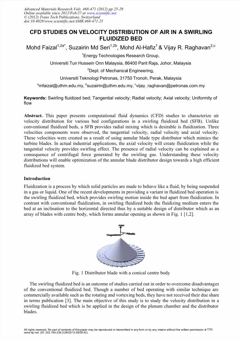
bed at an inclination to the horizontal directed thus by a suitable design of distributor which as an
array of blades with centre body which forms annular opening as shown in Fig 1 [12]
Fig 1 Distributor blade with a conical centre body
The swirling fluidized bed is an outcome of studies carried out in order to overcome disadvantages
of the conventional fluidized bed Though a number of bed operating with similar technique are
commercially available such as the rotating and vortexing beds they have not received their due share
in terms publication [3] The main objective of this study is to study the velocity distribution in aswirling fluidized bed which is be applied in the design of the plenum chamber and the distributor
blades
Advanced Materials Research Vols 468-471 (2012) pp 25-29Online available since 2012Feb27 at wwwscientificnet copy (2012) Trans Tech Publications Switzerland doi104028wwwscientificnetAMR468-47125
All rights reserved No part of contents of this paper may be reproduced or transmitted in any form or by any means without the written permission of TTPwwwttpnet (ID 2021842362-280212080842)
8112019 CFD Studies in SFB
httpslidepdfcomreaderfullcfd-studies-in-sfb 26
Methodology
Investigation of the air flow distribution in a SFB was conducted using commercial CFD software ndash
FLUENT 63 The computation domain and grid generation was developed via GAMBIT Two
parameters were changed to obtain the correlation between the bladersquos geometry with the air flow
distribution in the SFB is shown in Table 1 Simulation was done using Intel(R) Core(TM) i7 CPU
and at 280 GHz processor with 12 GB of RAM which runs on Windows 7 with 64 bit OperatingSystem
Table 1 Swirling fluidized bed distributor configuration
Case Number of BladeAngle of
Blade
1 30 10o
2 30 12o
3 30 15o
4 45 10o
5 45 12o
6 45 15o
7 60 10o
8 60 12o
9 60 15o
Actual SFB System and Simplified Computation Domain The actual system computation
domain and simplified computation domain via periodic boundary is depicted in Fig 2
Fig 2 SFB actual system and computation domain in CFD
Periodic Boundry Simulation of a SFB on actual scale will result high computation time This isdue to large amount of calculations will be carried out by the computer Therefore periodic boundary
was applied on the model by slicing the model into three symmetric sections as in Fig 2
Result and Discussion
Computational time for the whole simulations took 1517 hours The tangential radial and axial
velocities and the pressure drop of the system were studied Data was extracted on a horizontal plane
10 mm above the distributor since this was the suitable location to study the air flow characteristics
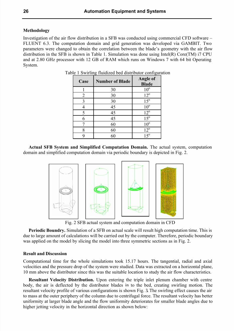
Resultant Velocity Distribution Upon entering the triple inlet plenum chamber with centre
body the air is deflected by the distributor blades in to the bed creating swirling motion The
resultant velocity profile of various configurations is shown Fig 3 The swirling effect causes the airto mass at the outer periphery of the column due to centrifugal force The resultant velocity has better
uniformity at larger blade angle and the flow uniformity deteriorates for smaller blade angles due to
higher jetting velocity in the horizontal direction as shown below
26 Automation Equipment and Systems
8112019 CFD Studies in SFB
httpslidepdfcomreaderfullcfd-studies-in-sfb 36
Fig 3 Velocity distribution at various blade inclination (a) 10deg (b) 12deg and (c) 15deg
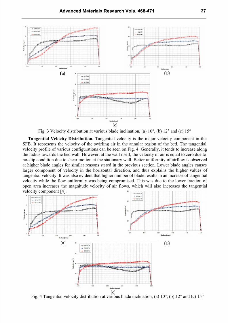
Tangential Velocity Distribution Tangential velocity is the major velocity component in the
SFB It represents the velocity of the swirling air in the annular region of the bed The tangential
velocity profile of various configurations can be seen on Fig 4 Generally it tends to increase along
the radius towards the bed wall However at the wall itself the velocity of air is equal to zero due to
no-slip condition due to shear motion at the stationary wall Better uniformity of airflow is observed
at higher blade angles for similar reasons stated in the previous section Lower blade angles causes
larger component of velocity in the horizontal direction and thus explains the higher values oftangential velocity It was also evident that higher number of blade results in an increase of tangential
velocity while the flow uniformity was being compromised This was due to the lower fraction of
open area increases the magnitude velocity of air flows which will also increases the tangential
velocity component [4]
Fig 4 Tangential velocity distribution at various blade inclination (a) 10deg (b) 12deg and (c) 15deg
983138
983080983139983081
983137
983138
983080983139983081
983080983137983081
Advanced Materials Research Vols 468-471 27
8112019 CFD Studies in SFB
httpslidepdfcomreaderfullcfd-studies-in-sfb 46
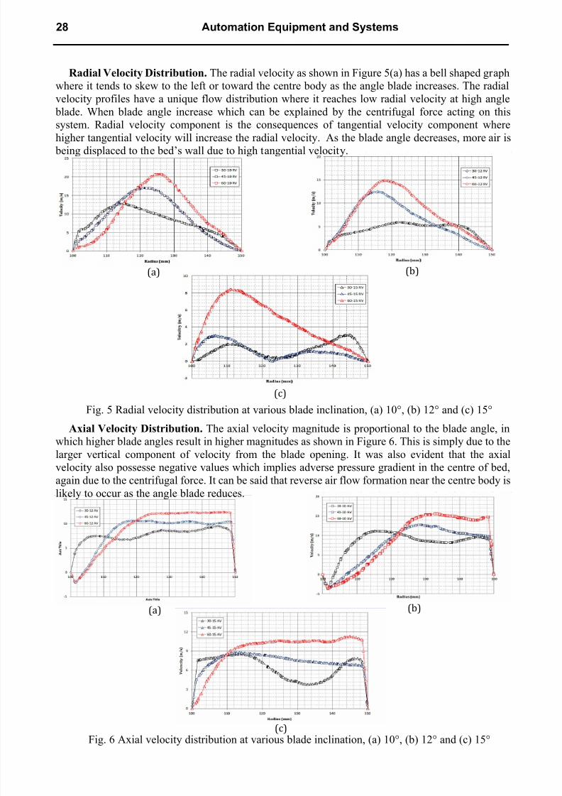
Radial Velocity Distribution The radial velocity as shown in Figure 5(a) has a bell shaped graph
where it tends to skew to the left or toward the centre body as the angle blade increases The radial
velocity profiles have a unique flow distribution where it reaches low radial velocity at high angle
blade When blade angle increase which can be explained by the centrifugal force acting on this
system Radial velocity component is the consequences of tangential velocity component where
higher tangential velocity will increase the radial velocity As the blade angle decreases more air is being displaced to the bedrsquos wall due to high tangential velocity
Fig 5 Radial velocity distribution at various blade inclination (a) 10deg (b) 12deg and (c) 15deg
Axial Velocity Distribution The axial velocity magnitude is proportional to the blade angle in
which higher blade angles result in higher magnitudes as shown in Figure 6 This is simply due to the
larger vertical component of velocity from the blade opening It was also evident that the axial
velocity also possesse negative values which implies adverse pressure gradient in the centre of bed
again due to the centrifugal force It can be said that reverse air flow formation near the centre body is
likely to occur as the angle blade reduces
Fig 6 Axial velocity distribution at various blade inclination (a) 10deg (b) 12deg and (c) 15deg
983080983138983081
983080983139983081
983080983137983081
983080983138983081
983080983139983081
983080983137983081
28 Automation Equipment and Systems
8112019 CFD Studies in SFB
httpslidepdfcomreaderfullcfd-studies-in-sfb 56
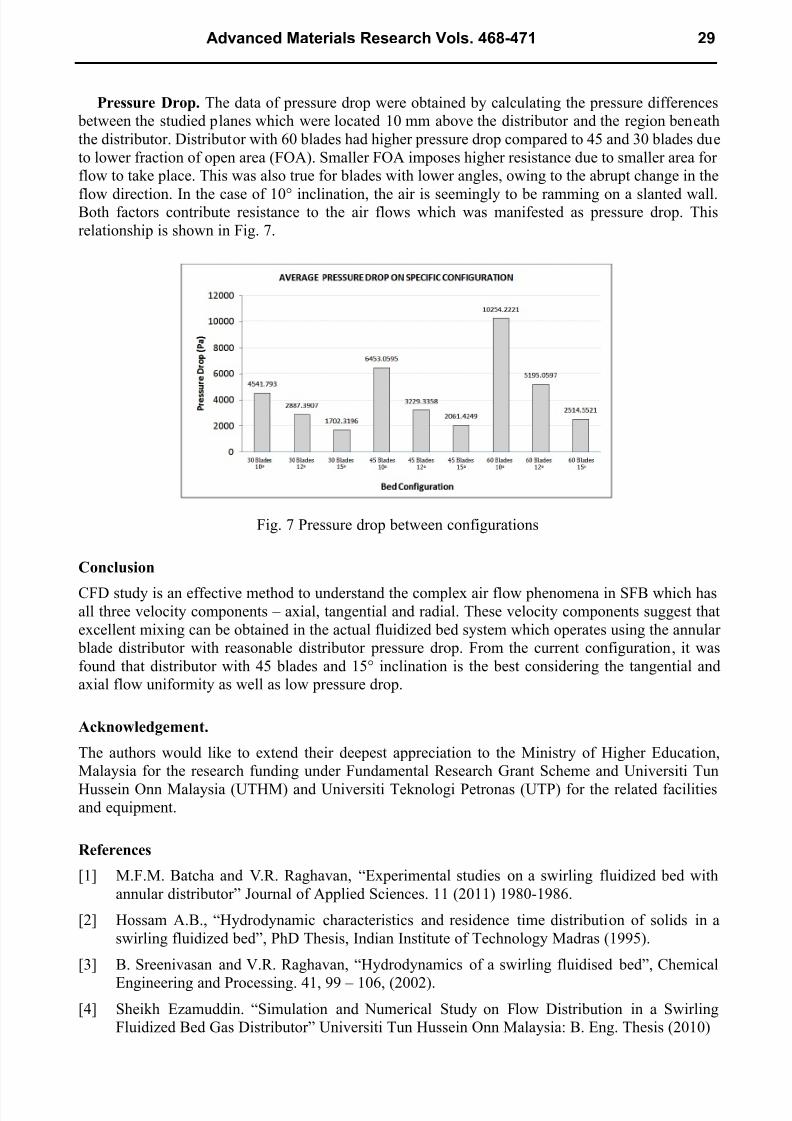
Pressure Drop The data of pressure drop were obtained by calculating the pressure differences
between the studied planes which were located 10 mm above the distributor and the region beneath
the distributor Distributor with 60 blades had higher pressure drop compared to 45 and 30 blades due
to lower fraction of open area (FOA) Smaller FOA imposes higher resistance due to smaller area for
flow to take place This was also true for blades with lower angles owing to the abrupt change in the
flow direction In the case of 10deg inclination the air is seemingly to be ramming on a slanted wallBoth factors contribute resistance to the air flows which was manifested as pressure drop This
relationship is shown in Fig 7
Fig 7 Pressure drop between configurations
Conclusion
CFD study is an effective method to understand the complex air flow phenomena in SFB which hasall three velocity components ndash axial tangential and radial These velocity components suggest that
excellent mixing can be obtained in the actual fluidized bed system which operates using the annular
blade distributor with reasonable distributor pressure drop From the current configuration it was
found that distributor with 45 blades and 15deg inclination is the best considering the tangential and
axial flow uniformity as well as low pressure drop
Acknowledgement
The authors would like to extend their deepest appreciation to the Ministry of Higher Education
Malaysia for the research funding under Fundamental Research Grant Scheme and Universiti Tun
Hussein Onn Malaysia (UTHM) and Universiti Teknologi Petronas (UTP) for the related facilitiesand equipment
References
[1] MFM Batcha and VR Raghavan ldquoExperimental studies on a swirling fluidized bed with
annular distributorrdquo Journal of Applied Sciences 11 (2011) 1980-1986
[2] Hossam AB ldquoHydrodynamic characteristics and residence time distribution of solids in a
swirling fluidized bedrdquo PhD Thesis Indian Institute of Technology Madras (1995)
[3] B Sreenivasan and VR Raghavan ldquoHydrodynamics of a swirling fluidised bedrdquo Chemical
Engineering and Processing 41 99 ndash 106 (2002)
[4] Sheikh Ezamuddin ldquoSimulation and Numerical Study on Flow Distribution in a Swirling
Fluidized Bed Gas Distributorrdquo Universiti Tun Hussein Onn Malaysia B Eng Thesis (2010)
Advanced Materials Research Vols 468-471 29
8112019 CFD Studies in SFB
httpslidepdfcomreaderfullcfd-studies-in-sfb 66
Automation Equipment and Systems
104028wwwscientificnetAMR468-471
CFD Studies on Velocity Distribution of Air in a Swirling Fluidized Bed
104028wwwscientificnetAMR468-47125
8112019 CFD Studies in SFB
httpslidepdfcomreaderfullcfd-studies-in-sfb 26
Methodology
Investigation of the air flow distribution in a SFB was conducted using commercial CFD software ndash
FLUENT 63 The computation domain and grid generation was developed via GAMBIT Two
parameters were changed to obtain the correlation between the bladersquos geometry with the air flow
distribution in the SFB is shown in Table 1 Simulation was done using Intel(R) Core(TM) i7 CPU
and at 280 GHz processor with 12 GB of RAM which runs on Windows 7 with 64 bit OperatingSystem
Table 1 Swirling fluidized bed distributor configuration
Case Number of BladeAngle of
Blade
1 30 10o
2 30 12o
3 30 15o
4 45 10o
5 45 12o
6 45 15o
7 60 10o
8 60 12o
9 60 15o
Actual SFB System and Simplified Computation Domain The actual system computation
domain and simplified computation domain via periodic boundary is depicted in Fig 2
Fig 2 SFB actual system and computation domain in CFD
Periodic Boundry Simulation of a SFB on actual scale will result high computation time This isdue to large amount of calculations will be carried out by the computer Therefore periodic boundary
was applied on the model by slicing the model into three symmetric sections as in Fig 2
Result and Discussion
Computational time for the whole simulations took 1517 hours The tangential radial and axial
velocities and the pressure drop of the system were studied Data was extracted on a horizontal plane
10 mm above the distributor since this was the suitable location to study the air flow characteristics
Resultant Velocity Distribution Upon entering the triple inlet plenum chamber with centre
body the air is deflected by the distributor blades in to the bed creating swirling motion The
resultant velocity profile of various configurations is shown Fig 3 The swirling effect causes the airto mass at the outer periphery of the column due to centrifugal force The resultant velocity has better
uniformity at larger blade angle and the flow uniformity deteriorates for smaller blade angles due to
higher jetting velocity in the horizontal direction as shown below
26 Automation Equipment and Systems
8112019 CFD Studies in SFB
httpslidepdfcomreaderfullcfd-studies-in-sfb 36
Fig 3 Velocity distribution at various blade inclination (a) 10deg (b) 12deg and (c) 15deg
Tangential Velocity Distribution Tangential velocity is the major velocity component in the
SFB It represents the velocity of the swirling air in the annular region of the bed The tangential
velocity profile of various configurations can be seen on Fig 4 Generally it tends to increase along
the radius towards the bed wall However at the wall itself the velocity of air is equal to zero due to
no-slip condition due to shear motion at the stationary wall Better uniformity of airflow is observed
at higher blade angles for similar reasons stated in the previous section Lower blade angles causes
larger component of velocity in the horizontal direction and thus explains the higher values oftangential velocity It was also evident that higher number of blade results in an increase of tangential
velocity while the flow uniformity was being compromised This was due to the lower fraction of
open area increases the magnitude velocity of air flows which will also increases the tangential
velocity component [4]
Fig 4 Tangential velocity distribution at various blade inclination (a) 10deg (b) 12deg and (c) 15deg
983138
983080983139983081
983137
983138
983080983139983081
983080983137983081
Advanced Materials Research Vols 468-471 27
8112019 CFD Studies in SFB
httpslidepdfcomreaderfullcfd-studies-in-sfb 46
Radial Velocity Distribution The radial velocity as shown in Figure 5(a) has a bell shaped graph
where it tends to skew to the left or toward the centre body as the angle blade increases The radial
velocity profiles have a unique flow distribution where it reaches low radial velocity at high angle
blade When blade angle increase which can be explained by the centrifugal force acting on this
system Radial velocity component is the consequences of tangential velocity component where
higher tangential velocity will increase the radial velocity As the blade angle decreases more air is being displaced to the bedrsquos wall due to high tangential velocity
Fig 5 Radial velocity distribution at various blade inclination (a) 10deg (b) 12deg and (c) 15deg
Axial Velocity Distribution The axial velocity magnitude is proportional to the blade angle in
which higher blade angles result in higher magnitudes as shown in Figure 6 This is simply due to the
larger vertical component of velocity from the blade opening It was also evident that the axial
velocity also possesse negative values which implies adverse pressure gradient in the centre of bed
again due to the centrifugal force It can be said that reverse air flow formation near the centre body is
likely to occur as the angle blade reduces
Fig 6 Axial velocity distribution at various blade inclination (a) 10deg (b) 12deg and (c) 15deg
983080983138983081
983080983139983081
983080983137983081
983080983138983081
983080983139983081
983080983137983081
28 Automation Equipment and Systems
8112019 CFD Studies in SFB
httpslidepdfcomreaderfullcfd-studies-in-sfb 56
Pressure Drop The data of pressure drop were obtained by calculating the pressure differences
between the studied planes which were located 10 mm above the distributor and the region beneath
the distributor Distributor with 60 blades had higher pressure drop compared to 45 and 30 blades due
to lower fraction of open area (FOA) Smaller FOA imposes higher resistance due to smaller area for
flow to take place This was also true for blades with lower angles owing to the abrupt change in the
flow direction In the case of 10deg inclination the air is seemingly to be ramming on a slanted wallBoth factors contribute resistance to the air flows which was manifested as pressure drop This
relationship is shown in Fig 7
Fig 7 Pressure drop between configurations
Conclusion
CFD study is an effective method to understand the complex air flow phenomena in SFB which hasall three velocity components ndash axial tangential and radial These velocity components suggest that
excellent mixing can be obtained in the actual fluidized bed system which operates using the annular
blade distributor with reasonable distributor pressure drop From the current configuration it was
found that distributor with 45 blades and 15deg inclination is the best considering the tangential and
axial flow uniformity as well as low pressure drop
Acknowledgement
The authors would like to extend their deepest appreciation to the Ministry of Higher Education
Malaysia for the research funding under Fundamental Research Grant Scheme and Universiti Tun
Hussein Onn Malaysia (UTHM) and Universiti Teknologi Petronas (UTP) for the related facilitiesand equipment
References
[1] MFM Batcha and VR Raghavan ldquoExperimental studies on a swirling fluidized bed with
annular distributorrdquo Journal of Applied Sciences 11 (2011) 1980-1986
[2] Hossam AB ldquoHydrodynamic characteristics and residence time distribution of solids in a
swirling fluidized bedrdquo PhD Thesis Indian Institute of Technology Madras (1995)
[3] B Sreenivasan and VR Raghavan ldquoHydrodynamics of a swirling fluidised bedrdquo Chemical
Engineering and Processing 41 99 ndash 106 (2002)
[4] Sheikh Ezamuddin ldquoSimulation and Numerical Study on Flow Distribution in a Swirling
Fluidized Bed Gas Distributorrdquo Universiti Tun Hussein Onn Malaysia B Eng Thesis (2010)
Advanced Materials Research Vols 468-471 29
8112019 CFD Studies in SFB
httpslidepdfcomreaderfullcfd-studies-in-sfb 66
Automation Equipment and Systems
104028wwwscientificnetAMR468-471
CFD Studies on Velocity Distribution of Air in a Swirling Fluidized Bed
104028wwwscientificnetAMR468-47125
8112019 CFD Studies in SFB
httpslidepdfcomreaderfullcfd-studies-in-sfb 56
Pressure Drop The data of pressure drop were obtained by calculating the pressure differences
between the studied planes which were located 10 mm above the distributor and the region beneath
the distributor Distributor with 60 blades had higher pressure drop compared to 45 and 30 blades due
to lower fraction of open area (FOA) Smaller FOA imposes higher resistance due to smaller area for
flow to take place This was also true for blades with lower angles owing to the abrupt change in the
flow direction In the case of 10deg inclination the air is seemingly to be ramming on a slanted wallBoth factors contribute resistance to the air flows which was manifested as pressure drop This
relationship is shown in Fig 7
Fig 7 Pressure drop between configurations
Conclusion
CFD study is an effective method to understand the complex air flow phenomena in SFB which hasall three velocity components ndash axial tangential and radial These velocity components suggest that
excellent mixing can be obtained in the actual fluidized bed system which operates using the annular
blade distributor with reasonable distributor pressure drop From the current configuration it was
found that distributor with 45 blades and 15deg inclination is the best considering the tangential and
axial flow uniformity as well as low pressure drop
Acknowledgement
The authors would like to extend their deepest appreciation to the Ministry of Higher Education
Malaysia for the research funding under Fundamental Research Grant Scheme and Universiti Tun
Hussein Onn Malaysia (UTHM) and Universiti Teknologi Petronas (UTP) for the related facilitiesand equipment
References
[1] MFM Batcha and VR Raghavan ldquoExperimental studies on a swirling fluidized bed with
annular distributorrdquo Journal of Applied Sciences 11 (2011) 1980-1986
[2] Hossam AB ldquoHydrodynamic characteristics and residence time distribution of solids in a
swirling fluidized bedrdquo PhD Thesis Indian Institute of Technology Madras (1995)
[3] B Sreenivasan and VR Raghavan ldquoHydrodynamics of a swirling fluidised bedrdquo Chemical
Engineering and Processing 41 99 ndash 106 (2002)
[4] Sheikh Ezamuddin ldquoSimulation and Numerical Study on Flow Distribution in a Swirling
Fluidized Bed Gas Distributorrdquo Universiti Tun Hussein Onn Malaysia B Eng Thesis (2010)
Advanced Materials Research Vols 468-471 29
8112019 CFD Studies in SFB
httpslidepdfcomreaderfullcfd-studies-in-sfb 66
Automation Equipment and Systems
104028wwwscientificnetAMR468-471
CFD Studies on Velocity Distribution of Air in a Swirling Fluidized Bed
104028wwwscientificnetAMR468-47125

8112019 CFD Studies in SFB
httpslidepdfcomreaderfullcfd-studies-in-sfb 66
Automation Equipment and Systems
104028wwwscientificnetAMR468-471
CFD Studies on Velocity Distribution of Air in a Swirling Fluidized Bed
104028wwwscientificnetAMR468-47125