scaling studies and conceptual experiment...
TRANSCRIPT
INEEL/EXT-04-02502
Scaling Studies and Conceptual Experiment Designs for NGNP CFD Assessment D. M. McEligot and G. E. McCreery 30 November 2004
Idaho National Engineering and Environmental Laboratory Bechtel BWXT Idaho, LLC


INEEL/EXT-04-02502
Scaling studies and conceptual experiment designs for NGNP CFD assessment
D. M. McEligot and G. E. McCreery
30 November 2004
Idaho National Engineering and Environmental Laboratory Idaho Falls, Idaho 83415
Prepared for U. S. Department of Energy
Office of Nuclear Energy, Science and Technology Under DoE Idaho Operations Office
Contract DE-AC07-99ID13727

ii

iii
Abstract
Scaling studies and conceptual experiment designs for NGNP CFD assessment
Donald M. McEligot and Glenn E. McCreery Idaho National Engineering and Environmental Laboratory (INEEL)
Idaho Falls, Idaho 83415 USA
The objective of this report is to document scaling studies and conceptual designs for flow and heat transfer experiments intended to assess CFD codes and their turbulence models proposed for application to prismatic NGNP concepts. The general approach of the project is to develop new benchmark experiments for assessment in parallel with CFD and coupled CFD/systems code calculations for the same geometry. Two aspects of the complex flow in an NGNP are being addressed: (1) flow and thermal mixing in the lower plenum ("hot streaking" issue) and (2) turbulence and resulting temperature distributions in reactor cooling channels ("hot channel" issue). Current prismatic NGNP concepts are being examined to identify their proposed flow conditions and geometries over the range from normal operation to decay heat removal in a pressurized cooldown. Approximate analyses have been applied to determine key non-dimensional parameters and their magnitudes over this operating range. For normal operation, the flow in the coolant channels can be considered to be dominant turbulent forced convection with slight transverse property variation. In a pressurized cooldown (LOFA) simulation, the flow quickly becomes laminar with some possible buoyancy influences. The flow in the lower plenum can locally be considered to be a situation of multiple hot jets into a confined crossflow -- with obstructions. Flow is expected to be turbulent with momentum-dominated turbulent jets entering; buoyancy influences are estimated to be negligible in normal full power operation. Experiments are needed for the combined features of the lower plenum flows. Missing from the typical jet experiments available are interactions with nearby circular posts and with vertical posts in the vicinity of vertical walls - with near stagnant surroundings at one extreme and significant crossflow at the other.
Two types of heat transfer experiments are being considered. One addresses the "hot channel" problem, if necessary. The second type will treat heated jets entering a model plenum. Unheated MIR (Matched-Index-of-Refraction) experiments are first steps when the geometry is complicated. One does not want to use a computational technique which will not even handle constant properties properly. The purpose of the fluid dynamics experiments is to develop benchmark databases for the assessment of CFD solutions of the momentum equations, scalar mixing and turbulence models for typical NGNP plenum geometries in the limiting case of negligible buoyancy and constant fluid properties. As indicated by the scaling studies, in normal full power operation of a typical NGNP conceptual design, buoyancy influences should be negligible in the lower plenum. The MIR experiment will simulate flow features of the paths of jets as they mix in flowing through the array of posts in a lower plenum en route to the single exit duct. Conceptual designs for such experiments are described.

iv
Table of contents
Abstract ....................................................................................................................................................... iii
Table of contents ..........................................................................................................................................iv
Nomenclature ................................................................................................................................................v
Introduction ...................................................................................................................................................1
Background.........................................................................................................................................1
Thermal fluid considerations for safety analyses................................................................................2
Present R&D project for improved modeling and benchmark studies ...............................................6
Scaling studies for experiment design.........................................................................................................10
Heated vertical tube ("hot channel" issue)........................................................................................11
Lower plenum ("hot streaking" issue) ..............................................................................................21
Experimental needs .....................................................................................................................................26
Heated vertical tube ..........................................................................................................................27
Lower plenum...................................................................................................................................33
Heated flow experiments.............................................................................................................................39
Vertical tube......................................................................................................................................39
Lower plenum...................................................................................................................................43
Fluid dynamics experiments for lower plenum...........................................................................................48
INEEL Matched-Index-of-Refraction flow system ..........................................................................48
Experiment concepts.........................................................................................................................52
Concluding remarks ....................................................................................................................................58
References cited ..........................................................................................................................................63

v
Nomenclature
{ } function of Acs flow area
C empirical coefficient cp specific heat at constant pressure
D diameter Dh hydraulic diameter, 4 Acs / Pw
d wire diameter g acceleration of gravity gc units conversion factor, e.g., 1 kg m / (N s2), 32.1739 lbm ft / (lbf sec2)
G mean mass flux, m& / Acs
H lower plenum height; also height of idealized column of gas h convective heat transfer coefficient k thermal conductivity, turbulent kinetic energy m& mass flow rate P perimeter; Pw, wetted; Ph, heated surface
p pressure, pitch q" heat flux; q"w, wall heat flux
r radius T temperature U, V mean velocity Vb bulk or mixed-mean streamwise velocity uτ friction velocity, (gc τw / ρ)1/2
u v Reynolds shear stress v velocity fluctuation about mean x axial location
Non-dimensional quantities
Ac general acceleration onset parameter (see text) Bo general buoyancy onset parameter (see text) Bo* Jackson buoyancy parameter, Gr* / (ReDh3.425 Pr0.8) d+ wire diameter, d uτ / ν f, fτ friction factor, 2 ρb gc τw / G2 Frj jet Froude number (see text) G Grashof number as used by Scheele and Hanratty [1962], g β q"wall rw4 / (k ν2)

vi
Gr* Grashof number based on heat flux, g β q"wall Dh4 / (k ν2) Grws modified Grashof number of Worsoe-Schmidt [1966], g D3 / ν2 Kv acceleration parameter, (νb / Vb2) (dVb / dx) Nu Nusselt number, h Dh / kb Pr Prandtl number, cp µ/k
Q+ heat flux for laminar analyses by Worsoe-Schmidt [1966], rw q"wall / (k T) q+ heat flux, β q"wall / (G cp) R Reynolds number as used by Scheele and Hanratty [1962], Vb rw / ν Re Reynolds number, 4 m& / Π D µ; ReDh, based on hydraulic diameter, G Dh / µ Ri overall Richardson number, g (ρ1-ρ2) H / (ρ1 Vb2) Riwall Richardson number defined in terms of wall quantities (see text)
Greek symbols
β volumetric coefficient of expansion, - (1/ρ) (∂ρ/∂T)p
ε dissipation of turbulence kinetic energy µ absolute viscosity ν kinematic viscosity, µ / ρ ρ density τ shear stress; τw, wall shear stress
Subscripts
b evaluated at bulk or mixed-mean temperature (or enthalpy) D based on diameter DB Dittus-Boelter [1930] correlation Dh evaluated with hydraulic diameter f, fc forced convection i, in evaluated at inlet, entry j jet max maximum value p support post ref evaluated at reference conditions w, wall wall, evaluated at wall temperature

1
Introduction
Background
The ultimate goal of the present study is the improvement of predictive methods for design and safety analyses of advanced gas-cooled reactors (AGCRs) for higher efficiency and enhanced safety and for deployable reactors for electrical power generation, process heat utilization and hydrogen generation. While key applications would be very high temperature reactors (VHTRs) using the closed Brayton cycle (CBC) for higher efficiency (such as the proposed Next Generation Nuclear Plant), results of the proposed research should also be valuable in gas-cooled fast-spectrum reactor systems (GFRs) as well as reactors with supercritical-pressure flow. Higher efficiency leads to lower cost/kwh and reduces life-cycle impacts of radioactive waste (by reducing waste/kwh). The outcomes will also be useful for some space power and propulsion concepts and for some fusion reactor concepts as side benefits, but they are not the thrusts of the investigation.
The Next Generation Nuclear Plant (NGNP) is intended to meet three basic requirements: (1) a coolant outlet temperature of 1000 C, (2) passive safety and (3) a total power output consistent with that expected for commercial high-temperature gas-cooled reactors [MacDonald et al., 2003]. Both prismatic fuel types and pebble bed fuel types are being considered with helium as the coolant. The present study concentrates on issues for prismatic versions but some aspects are common to pebble bed designs. The prismatic NGNP Point Design is an evolutionary version with roots stemming from the Fort Saint Vrain high-temperature gas-cooled reactor; the immediate predecessor is the General Atomics gas turbine - modular helium reactor (GT-MHR) shown in Figure 1. Currently, modifications of the GT-MHR design are being proposed in order to meet the NGNP design requirements and, thereby, to identify issues and R&D needs pertinent to typical NGNP and VHTR designs which are expected to evolve.
Fig. 1. GT-MHR reactor which serves as the basis for the current prismatic NGNP Point Design [MacDonald et al., 2003].
Control Rod Drive Assembly
Refueling Stand Pipe
Control Rod Guide tubes
Cold leg Core Coolant Upper Plenum
Central Reflector Graphite
Annular shaped Active Core
Outer Side Reflector Graphite
Core Exit Hot Gas Plenum
Graphite Core Support Columns
Reactor Vessel
Upper Plenum Shroud
Shutdown Cooling System Module Hot Duct
Insulation Module
Cross Vessel Nipple
Hot Duct Structural Element
Metallic Core Support Structure
Core Inlet Flow
Core Outlet Flow
Insulation Layer for Metallic Core Support Plate
Upper Core Restraint Structure
Control Rods
7m(23 ft)
23.7m(78ft)
2.2m(7ft)
8.2m(27ft) Dia Vessel Flange
2
Advanced gas reactors and combined cycle concepts offer the potential of high thermal efficiency and enhanced safety [Kugeler, 1996]. Gas-cooled reactors are also ideal for use in small deployable systems; historically, one of the first GCRs was an Army reactor for this purpose, the ML-1 at NRTS (now INEEL). In addition to improving efficiency, AGCR-CBCs enhance system safety by removing steam and water components. Safety is inherently enhanced by avoidance of the steam cycle: no flashing or boiling is possible, there are no neutronic reactions with the coolant, no chemical reactions between coolant and fuel and no corrosive corrosion products. Passive safety features include a negative coefficient of reactivity, core power and power density, passive reactor cavity cooling systems and below-grade containment for protection from aircraft and terrorist actions.
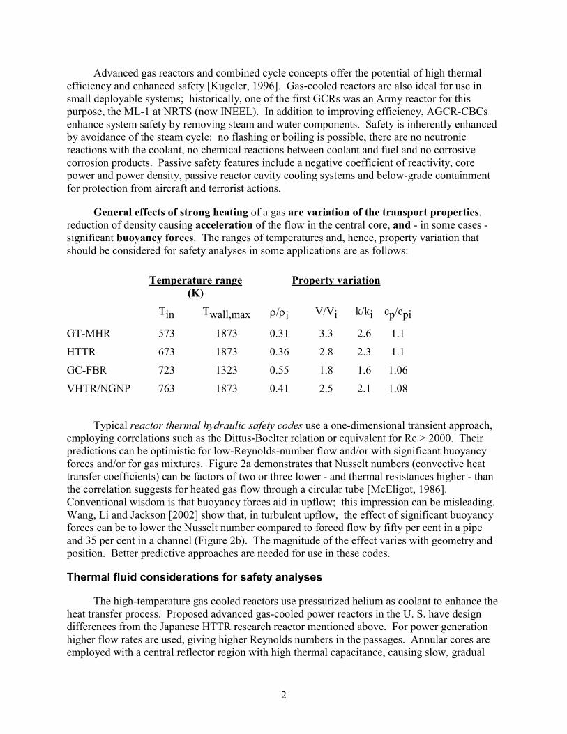
General effects of strong heating of a gas are variation of the transport properties, reduction of density causing acceleration of the flow in the central core, and - in some cases - significant buoyancy forces. The ranges of temperatures and, hence, property variation that should be considered for safety analyses in some applications are as follows:
Temperature range (K)
Property variation
Tin Twall,max ρ/ρi V/Vi k/ki cp/cpi
GT-MHR 573 1873 0.31 3.3 2.6 1.1
HTTR 673 1873 0.36 2.8 2.3 1.1
GC-FBR 723 1323 0.55 1.8 1.6 1.06
VHTR/NGNP 763 1873 0.41 2.5 2.1 1.08
Typical reactor thermal hydraulic safety codes use a one-dimensional transient approach, employing correlations such as the Dittus-Boelter relation or equivalent for Re > 2000. Their predictions can be optimistic for low-Reynolds-number flow and/or with significant buoyancy forces and/or for gas mixtures. Figure 2a demonstrates that Nusselt numbers (convective heat transfer coefficients) can be factors of two or three lower - and thermal resistances higher - than the correlation suggests for heated gas flow through a circular tube [McEligot, 1986]. Conventional wisdom is that buoyancy forces aid in upflow; this impression can be misleading. Wang, Li and Jackson [2002] show that, in turbulent upflow, the effect of significant buoyancy forces can be to lower the Nusselt number compared to forced flow by fifty per cent in a pipe and 35 per cent in a channel (Figure 2b). The magnitude of the effect varies with geometry and position. Better predictive approaches are needed for use in these codes.
Thermal fluid considerations for safety analyses
The high-temperature gas cooled reactors use pressurized helium as coolant to enhance the heat transfer process. Proposed advanced gas-cooled power reactors in the U. S. have design differences from the Japanese HTTR research reactor mentioned above. For power generation higher flow rates are used, giving higher Reynolds numbers in the passages. Annular cores are employed with a central reflector region with high thermal capacitance, causing slow, gradual

3
thermal response to disturbances. It is appropriate to consider three of several operating modes. Under extreme accident conditions these reactors can lose their capabilities for forced circulation of their coolant (Loss of Forced Cooling Accident, LOFA), and/or lose the capability of containing the coolant (Loss of Coolant Accident, LOCA).
Fig. 2. Typical correlations in reactor thermal hydraulics codes overpredict convective heat transfer parameters for gases in some scenarios: (a) at low Reynolds numbers in a circular tube [McEligot, 1986] and (b) with buoyant effects in turbulent upflow through circular tubes and rectangular channels [Wang, Li and Jackson, 2002].
The design for full power operation is intended to be a steady-state condition. Flow and, therefore, Reynolds numbers in the coolant passages are large so forced convection dominates the heat transfer problem. Typical Reynolds numbers are of the order of 50,000; consequently, buoyancy forces and thermal radiation are not significant and the phenomenon of laminarization is unlikely. A concern during this mode of operation is the potential damage to metallic components from local hot "streaks" caused by poor mixing of the high-temperature jets that enter the lower plenum from the hottest coolant channels (Figure 3). The temperature, momentum and turbulence profiles of the gas exiting the channels serve as initial conditions for the passages forming these jets.
During partial load operations (e.g., as low as fifteen per cent of the design power) the helium inventory is reduced to maintain the same volumetric flow rate at the turbine inlet. Under these conditions the typical Reynolds number within the core coolant passages may be reduced to values around 5, 000 or lower, at which point a potential transition from turbulent to laminar flow could occur. Computational techniques with supporting test data may be needed to address the heat transfer from the fuel to the coolant during this transition from turbulent to laminar flow, including the possibility of an early laminarization of the flow.

4
Concern: Spatial variations in local fission rate and material behavior will cause “hot channels” which may cause “hot streaking” in the lower plenum – and possible structural problems
Annular shaped Active Core
Outer Side Reflector Graphite
Core Exit Hot Gas Plenum
Graphite Core Support Columns
Shutdown Cooling System Module Hot Duct
Insulation Module
Cross Vessel Nipple
Hot Duct Structural Element
Metallic Core Support Structure
Core Inlet Flow
Core Outlet Flow
Insulation Layer for Metallic Core Support Plate
Adequate?
Modify?
Turbine Inlet"Pattern Factor"
Fig. 3. Relation of "hot channel" and "hot streaking" issues.
The prediction of the turbulent mixing of the high temperature coolant jets that enter the lower plenum requires further development. Conditions of the flow through the lower plenum of the core during normal operation are expected to be in the following ranges:
Helium temperature 700 - 1000 C
Helium pressure 40 - 80 atm
Flow type Near stagnant to highly turbulent
The design issue in this case is the need for predicting the rates of turbulent mixing occurring between the hotter coolant jets and the rest of the flow before these hot jets impinge on the metallic components at the exit or on the insulation layer on the floor of the core lower plenum (Figure 3). Due to the complexity of the flow path in the lower plenum, computational techniques with supporting test data are needed to address this turbulent mixing process.
The most extreme accident scenario is believed to be a LOFA/LOCA = a simultaneous Loss of Flow Accident and Loss of Coolant Accident (also called "low pressure conduction cooldown"). The compressors stop so there is no flow. The coolant leaks to atmospheric pressure so there is no significant residual coolant in the channels as opposed to the high pressure operating condition. Allowable temperatures are high, e.g., 1600 C for the central region. The main thermal problems become thermal conduction and thermal radiation. Since the Grashof

5
number varies as ρ2, it drops to near zero; vendor estimates show that heat transfer in the reactor by natural convection would be less than 0.1 per cent of the heat transfer rate. The important thermal questions become adequate evaluation of the thermal capacitances of the various materials in the reactor and the thermal emissivity of the exposed surfaces involved, particularly the metals used in the reactor internals, the vessel and the cooling panels of the passive cavity cooling system.
A scenario likely to occur more frequently is the LOFA alone (also called "pressurized cooldown"). Coolant is not lost so helium remains at its high pressure operating condition. Conditions are expected to be:
Helium temperature 400 - 1600 C
Helium pressure 40 - 80 atm
Flow type Overall natural circulation
Due to the high thermal capacitance of the structure, the transient problem is quasi-steady as far as the fluid physics is concerned. That is, fluid residence times in the passages are much shorter than the characteristic thermal response times of the solids forming the passage surfaces and determining the thermal boundary conditions; the convection problem can be treated as instantaneously steady. The flow varies from its initial high Reynolds number to near zero as the temperature differences are reduced, approaching thermal equilibrium. During this transient the flow sequentially passes from the high-Reynolds-number turbulent regime, though the low-Reynolds-number turbulent and laminarizing regimes, to laminar flow both upwards and downwards. For predictions, the most difficult and uncertain conditions are expected to be the low-Reynolds-number turbulent and laminarizing flows, particularly with gas property variation and complex geometries. Also of concern is the mixing of the hot plumes from the core into the upper plenum during this accident scenario (comparable to the jets into the lower plenum during normal operation).
During a LOFA accident there are two more cases of buoyancy-driven flow phenomena specific to gas-cooled reactor design that are of interest: (1) the flow between the inner hotter and the outer cooler channels within the core and (2) the flow between the reactor containment vessel outer surface and the cooling panels of the passive cooling system that encircle the vessel. In both cases, natural circulation is induced by differences in buoyancy forces but within the passages themselves the flow may be expected to be predominantly forced by the pressure difference between the upper and lower plena (although this forced convection may be modified by buoyancy forces within the passages and thermal radiation across them). In the cooling channels the fluid is typically high pressure helium and in the cavity cooling system it would be air or an air-helium mixture at atmospheric pressure (the higher thermal conductivity of helium in such a mixture can be an advantage in passive cooling systems [McEligot and Taylor, 1996]). Design issues are
• prediction of the buoyancy-driven coolant flow between hotter and cooler core channels

6
• evaluation of the thermal mixing of hot plumes in the core upper plenum before they reach metallic components and
• need for an accurate prediction of the maximum fuel temperature of the reactor core.
This temperature is directly correlated to a clear understanding of the buoyancy-driven heat transfer within the core and outside the reactor vessel.
The Modular Helium Reactor (MHR), which serves as the design predecessor of the prismatic NGNP Point Design, is considered to be an ultra-safe, meltdown-proof, helium-cooled reactor which is based on thirty years of high temperature gas-cooled reactor experience and is representative of a Generation IV advanced reactor design. The MHR takes advantage of the unique properties of helium gas as coolant, graphite as moderator and coated particles as fuels. The Gas Turbine-Modular Helium Reactor (GT-MHR) couples the helium-cooled modular reactor core with a gas turbine to produce electricity directly from the high-temperature helium coolant at efficiencies approaching fifty per cent. One of the inherent safety features of gas-cooled reactors is their capability of maintaining a gas environment for cooling the core under a major loss of containment. During normal operation the thermal energy from the core is removed by forced convection and during severe accidents, in which the coolant forced flow and/or the coolant containment is lost, it is removed by conduction, radiation and/or natural circulation.
Present R&D project for improved modeling and benchmark studies
The goal of this ongoing R&D effort is to develop the analytical tools necessary for design, operation, safety studies, assessments and licensing for the proposed NGNP (Next Generation Nuclear Plant). The primary objectives of this coordinated experimental and computational research are:
• to build accurate, reliable numerical simulation models of important NGNP thermal-hydraulic phenomena
• to provide benchmark data for the assessment and improvement of thermal-hydraulic codes proposed for evaluating the NGNP design and
• to begin preliminary code development and assessment tasks based on identified modeling needs and existing data.
This study builds on the accomplishments of recent NERI and INERI projects led by INEEL [McEligot et al., 2002, 2003, 2004]. Its unique Matched-Index-of-Refraction flow system will be utilized for benchmark measurements to assess current and future modeling techniques to benefit NGNP and VHTR programs.
Meaningful feasibility studies for NGNP designs will require accurate, reliable predictions of material temperatures to evaluate the material capabilities. In a prismatic NGNP these temperatures depend on the thermal convection in the coolant channels for the core and in other important components. Unfortunately, correlations in one-dimensional system codes for gas-cooled reactors typically underpredict these temperatures, particularly in reduced power

7
operations and hypothesized accident scenarios. Likewise, most turbulence models in general-purpose CFD (computational fluid dynamics) codes provide optimistic predictions in the sense that surface temperatures are typically underpredicted [Mikielewicz et al., 2002; Richards, Spall and McEligot, 2004]. These treatments are further complicated by the non-homogeneous power distributions with strong peaking that can occur and buoyancy, strong pressure gradients and gas property variations in the channels ("hot channel" issue). DoE needs improved modeling capabilities, independently from the sometimes simplistic approaches employed by reactor vendors; these computational capabilities need, in turn, to be validated by comparison to experimental and analytical benchmark data.
The NGNP is presently based on the very high temperature reactor (VHTR) concept. The NGNP point design and the VHTR concept feature complex geometries and wide ranges of temperatures, leading to significant variations of the gas thermodynamic and transport properties plus possible effects of buoyancy during normal and reduced power operations and loss-of-flow scenarios. The complex geometries proposed have included non-circular fuel channels, high-temperature exit regions, plenum regions, regenerative heat exchangers, reactor cavities with cooling panels, etc.
Existing system safety codes provide reasonable predictions for high-Reynolds-number flows but their correlations can give misleading results for low-Reynolds-number gas flows with buoyancy, as in accident scenarios, even with simple circular tubes. Conceptually, CFD codes with turbulence models can yield predictions for improvement of correlations and preliminary design; however, as noted above recent assessments have shown that most turbulence models used in general purpose codes give unreliable, optimistic predictions for these cases. Further benchmark data are needed for complex geometries - to avoid this problem and to improve predictive capabilities. These bases can be obtained from direct numerical simulations (DNS) or large eddy simulations (LES), after validation with measurements, or by experiments. (DNS calculations are not currently part of this project but useful DNS databases are available from our current I-NERI project {McEligot et al., 2003].)
Six areas of thermal hydraulic phenomena -- in which the application of improved CFD (computational fluid dynamics) and system thermal-hydraulic analytical techniques can be used in the design and safety analyses of a prismatic NGNP -- have been identified [McEligot et al., 2002] as indicated in Figure 4. Several of these phenomena are pertinent to pebble bed versions of the NGNP as well. Our initial studies will concentrate on "Coolant flow distribution through reactor core channels" and "Mixing of hot jets in the reactor core lower plenum," phenomena that are important both in normal operation and in accident scenarios.
Accurate predictions of the thermal mixing in the lower plenum are needed to predict the temperature distribution of the coolant exit duct and its material behavior (Figure 3). Due to the variation of the heat generation across and along the core, the jets from the cooling channels into the plenum may vary in temperature substantially; if the turbulent mixing of these flows is incomplete, high temperature gas may impinge on lower plenum surfaces and / or the entrance of the core outlet flow duct causing potential structural problems ("hot streaking" issue). Non-uniformity of the gas temperature distribution in the outlet duct will also affect the high pressure turbine adversely. The geometric transition from the circular cooling channels in the core to the lower plenum is complex as is the configuration of the lower plenum itself with its array of posts

8
supporting the core. Hence, reliable, accurate predictive techniques are needed for the flow and mixing in the plenum and of the temperature and flow distributions of the hot jets entering the plenum ("hot channel" issue).
Loss of forced reactor core cooling (LOFA or “pressurized cooldown") - Mixing of hot plumes in the reactor core upper plenum - Coolant flow and temperature distributions through reactor core channels (natural circulation, "hot channel") - Rejection of heat by natural convection and thermal radiation at the vessel outer surface
Normal operation at full or partial loads - Mixing of hot jets in the reactor core lower plenum ("hot streaking") - Coolant flow and temperature distributions through reactor core channels ("hot channel")
Loss of forced reactor core cooling and loss of coolant inventory (LOCA or "depressurized cooldown") - Prediction of reactor core depressurized cooldown - conduction and thermal radiation - Rejection of heat by natural convection and thermal radiation at the vessel outer surface
Fig. 4. Pertinent areas of thermal hydraulic phenomena.
INEEL is extending the ATHENA/RELAP5-3D codes to treat flows in NGNPs and VHTRs. Under an LDRD program, ATHENA/RELAP5-3D has been linked to the Fluent CFD code to provide a tool capable of providing a macroscale flow resolution where adequate (core, piping, balance-of-plant) with a microscale flow resolution where it is necessary (inlet or outlet plenum). INEEL has recently led pertinent research projects for the NERI program ("Fundamental thermal fluid physics of high temperature flows in advanced reactors systems" [McEligot et al., 2002]) and the Korean I-NERI program ("Advanced computational thermal fluid physics and its assessment for supercritical reactors" [McEligot et al., 2003]). These computational and experimental projects both addressed effects of fluid property variation and complex geometries, key features of flows in NGNPs and VHTRs. INEEL partners developed LES (large eddy simulation) and DNS (direct numerical simulation) codes for low-Reynolds-number, strongly-heated, buoyant gas flows in channels to serve as benchmarks in those situations in gas-cooled reactors [McEligot et al., 2002, 2003].
INEEL has developed the World's largest Matched-Index-of-Refraction (MIR) flow system (http://www.inel.gov/env-energyscience/physics/mir/). By using optical techniques, such as laser Doppler velocimetry (LDV) and particle image velocimetry (PIV), measurements can be obtained in small complex passages without disturbing the flow. The refractive indices of the fluid and the model are matched so that there is no optical distortion. The large size provides
9
good spatial and temporal resolution. It was employed for velocity / turbulence data in scaled fuel channels for a VHTR concept and an SCWR concept. This facility provides means to measure flow fields, turbulence and mixing in the complex geometry of the NGNP lower plenum. The resulting data can be employed to assess CFD codes and their turbulence models for the limiting case of dominant forced convection where temperature can be considered to be a passive scalar; a code must satisfy this test before it can be considered for extension to include more complicated phenomena (e.g., buoyancy influences).
The general approach of the project is to develop new benchmark experiments for assessment in parallel with CFD and coupled CFD systems code calculations for the same geometry. Velocity and turbulence fields will be measured in INEEL's unique Matched-Index-of-Refraction (MIR) flow system, the World's largest; these data will be used to assess the capabilities of the CFD code and its turbulence models and to provide guidance in improving the models. Heat transfer experiments will also be developed and accomplished for the same purposes. Existing databases from experiments, direct numerical simulations and large eddy simulations will also be utilized where appropriate. A "lower plenum model," based on the point design of the NGNP, will be developed for the coupled CFD/ATHENA/RELAP5-3D codes and calculations will be performed to identify potential mixing problems ("hot streaking").
The INEEL CFD effort will employ the FLUENT code as a representative of typical commercial CFD codes that may be employed in NGNP / VHTR design and safety analyses. The FLUENT models developed will then be made available for coupling with the representative systems analysis code for systems level analyses. Initially, the data used for assessment of the model will be currently available results. Data generated in NERI Project 99-0254 will be perused and selected on the basis of applicability to the present project’s objectives. These data include those by Jackson and Li [2000a], Jackson and Li [2000b], Wu et al. [2001], Kim et al. [2002], Wang, Li and Jackson [2002], Wu, Xu and Jackson [2002] and DNS and LES databases. The models will be assessed against new measurements as they become available.
Outcomes of this proposed research will be (1) validated predictive techniques for gas flows with property variation and buoyancy effects through the complex geometries important in NGNP development, (2) benchmark data - both computational and experimental - for assessing existing and future CFD codes and (3) improved quantitative understanding of the limitations of current and proposed system and CFD codes.
Tasks initiated during FY-04 and continued into FY-05 include: 1) Scaling studies for experiment design 2) Conceptual design of heated experiments 3) Conceptual design of fluid dynamics experiments for lower plenum
Figure 5 describes the relations of these experimental tasks to each other and to research proposed for future years. The objective of the present report is to document the high temperature gas reactor scaling studies and conceptual experiment designs for gas flow and heat transfer.

10
Scaling
Needs
Heated experimentconcepts
Isothermal lower plenum flow experiment concepts
• Design• Fabrication• Measurements• Documentation
• Design• Fabrication• Measurements• Documentation
Coolant channels Lower plenum
Selection of first heated experiment
Pebble bed
exits?
Other important geometriesSecond heated experiment Fig. 5. Overview of proposed experimental tasks.
Scaling studies for experiment design
The objective of the benchmark experiments is to provide careful measurements to assess the capabilities and performance of the modeling approaches of CFD codes and systems codes. Two aspects of the complex flow in an NGNP will be addressed: (1) flow and thermal mixing in the lower plenum and (2) turbulence and resulting temperature distributions in reactor cooling channels ("hot channel" problem). Both normal operation and reduced power or accident scenarios will be considered.
The relations between these two regions have been demonstrated schematically in Figure 3. In the prismatic NGNP Point Design the cooling channels are simple vertical, circular tubes with complexity entering the problem due to the spatial variations in local fission rate and the temperature dependencies of the gas properties. The channels connecting the cooling channels to the lower plenum (Figure 6) and the lower plenum configuration itself introduce a variety of complex geometrical flow passages.
Current prismatic NGNP concepts are being examined to identify their proposed flow conditions and geometries over the range from normal operation to decay heat removal in a pressurized cooldown. Approximate analyses are being applied to determine key non-dimensional parameters and their magnitudes over this range. The ranges of these parameters in the reactor design identify the databases needed for assessment of codes (tools) that the NGNP "Integrator" will want to use. For example, for cooling channels key parameters would include the Reynolds number, Prandtl number, q+ (non-dimensional heat flux), Bo* (buoyancy) and Kv (streamwise acceleration as density decreases). From this information, geometries and desired operating conditions can be calculated for experiments representing channels and plena and dominant flow phenomena can be deduced. Preliminary model design can then be initiated and

11
tentative dimensions can be provided to CFD and systems modelers to calculate preliminary predictions which will assist in developing the measurement matrices (or modifying the apparatus).
GC00 0503 3
GT-MHRMHTGRHTGR, FSV HTTR
Fig. 6. Examples of designs for the geometric transitions from coolant channels to hot jet flows in the lower plenum of typical gas-cooled reactor cores.
Heated vertical tube ("hot channel" issue)
We first consider turbulent flow as in normal full power operation.
The so-called "deterioration" of turbulent convective heat transfer observed in some experiments with common gases can be due to radial property variation, acceleration, buoyancy or combinations of these phenomena, depending on the conditions of the applications [Hall and Jackson, 1969; McEligot, Coon and Perkins, 1970; Mikielewicz et al., 2002].
For pure forced convection in turbulent flow through an uninterrupted long duct at constant properties (i.e., low heating rates giving small temperature differences), the convective heat transfer from the fuel rods away from the entrance can typically be predicted by a relation of the form
NuDh ≈ C ReDh0.8 Pr0.4
as shown for internal flow in tubes by Dittus and Boelter [1930]. For gas flow in circular tubes this relation becomes
NuD ≈ 0.021 ReD0.8 Pr0.4

12
[Drexel and McAdams, 1945; McAdams, 1954, page 219; McEligot, Ormand and Perkins, 1966; Kawamura, 1979]; for predicting surface temperatures, it is important to recognize that this coefficient is ten per cent lower than the common textbook value (i.e., liquids). Other relations have been recommended for circular tubes but for Prandtl numbers near unity, most predict approximately the same magnitude [Taylor, Bauer and McEligot, 1988]. If one rearranges this relation to predict the convective heat transfer coefficient explicitly for a given mass flow rate and geometry, one sees that the variation with properties as the flow is heated along a duct takes the form
h ~ cp0.4 k0.6 / µ0.4
With "strong" heating, the temperature variation leads to fluid property variation which,
in turn, can cause several phenomena which may reduce or improve the convective heat transfer parameters. For gases, the property variations may be approximated by non-dimensional power laws as [Perkins, 1975]
(µ/µref) ≈ (T/Tref)a (k/kref) ≈ (T/Tref)b
(ρ/ρref) ≈ (p/pref) (Tref/T) (cp/cp,ref) ≈ (T/Tref)d
The variation of the properties across the flow will modify the fluid temperature distribution and the relation between the heat flux and the temperature difference, i.e., the convective heat transfer coefficient. This effect can often be accommodated by introducing property ratios such as µw/µb (or in the case of gases, Tw/Tb) in empirical correlations [Kays, 1966]. For moderate fluid property variation, Gersten and Herwig [Section 16.1.7g, 1992] have derived analytical predictions of the exponents to be applied to the property ratios and, hence, temperature ratio in such correlations. For gases, the modification of the Nusselt number will be less than about five per cent if the temperature ratio is less that about 1.1 [McEligot, 1986].
In addition to the property ratios, a non-dimensional heat flux
q+ = β q"wall / (G cp) where β = - (1/ρ) (∂ρ/∂T)p
can provide an indication of whether the Nusselt number may be significantly changed. This quantity (or a comparable one) evolves when one non-dimensionalizes the mathematical description for cases with specified wall heat flux distributions [Bankston and McEligot, 1970]. (The definition becomes q+ = q"wall / (G cp T) for fluids satisfying the perfect gas approximation.) For high-Reynolds-number flow without significant buoyancy or acceleration influences, a value of q+ < ~ 0.0005 is expected to induce a reduction in Nusselt number of less than five per cent as shown by an empirical correlation of McEligot, Magee and Leppert [1965].

13
Non-dimensionalization of the governing equations and their boundary conditions plus property variations shows that, in forced convection for a given geometry, the heat transfer coefficient can be represented as
Nu = Nu{ReDh, Pr, q+, a, b, d, x/Dh}
for gases at low Mach numbers satisfying the perfect gas approximation [Bankston and McEligot, 1970]. As noted above, the constants a, b and d are the exponents of the power law approximations for the properties and accommodate their dependencies on temperature. In turbulent flow the dependence on the distance from the thermal entry (x/Dh) becomes negligible after about thirty diameters. For typical gases, d is small and a and b are 0.5 to 1.0 approximately (for helium Worsoe-Schmidt [1966] employed a = b = 0.65 and d = 0.0) and the resulting function is not highly sensitive to small differences in their values. Thus, one can use the same correlation for data with air, nitrogen and helium [McEligot, Magee and Leppert, 1965]. In fact, for many gases the parameters q+, a, b and d can be replaced by a temperature ratio Tw/Tb raised to a fractional power as indicated above [Kays, 1966; Gersten and Herwig, 1992].
A significant variation of fluid properties across the flow makes it important for investigators to identify specifically at what temperature (or enthalpy) the properties are evaluated in their relations. There are many different definitions of the Reynolds number and, therefore, different magnitudes depending on the choices for property evaluation [McEligot, 1967, 1986]. Use of properties evaluated at the bulk enthalpy is usually most convenient for a designer in a case where the wall heat flux distribution is known because the enthalpy can be determined via an energy balance [Ward Smith, 1962]. It is also important to specify clearly the source of the fluid properties employed in the data analysis.
Heating of a fluid in a duct reduces its density so the velocity increases in the streamwise direction. This streamwise acceleration corresponds to a favorable streamwise pressure gradient, which is known to stabilize laminar boundary layers. One may hypothesize that for a turbulent flow, the acceleration would tend to stabilize bursting from the important viscous layer and thereby reduce turbulent transport [Corino and Brodkey, 1969]. With sufficiently large acceleration, a condition called "laminarization" can occur where flows expected to be turbulent show heat transfer parameters as low as in laminar flows [Bankston, 1970]. A measure of this phenomenon is an acceleration parameter Kv defined as (νb/Vb2) (dVb/dx) [McEligot, Coon and Perkins, 1970]. For an arbitrary cross section with some unheated surfaces, this parameter can be shown to be
Kv ≈ 4 (Ph/Pw) q+ / ReDh
which reduces to
Kv ≈ 4 q+ / ReD

14
for circular tubes. Moretti and Kays [1965] suggested that for Kv less than about 3 x 10⁻⁶ the flow would remain turbulent while for higher values it is likely to laminarize, giving a substantial reduction in heat transfer parameters. For flows accelerated by lateral convergence, Murphy, Chambers and McEligot [1983] found agreement with turbulent predictions when Kv < ~ 9.5 x 10⁻⁷ and agreement with laminar predictions when Kv > ~ 4 x 10⁻⁶.
If buoyancy forces become significant in vertical turbulent flow through a heated duct, the convective heat transfer can become inhibited in upflow while in downflow it could be enhanced; these observations are opposite to those for laminar flow and are not as one might expect [Jackson, Cotton and Axcell, 1989]. With a specified wall heat flux, the Grashof number is usually defined as
Gr* = g β q"wall Dh4 / (k ν2)
Jackson [Mikielewicz et al., 2002] developed an approximate analysis for the onset of buoyancy influences in fully-established flow in terms of a buoyancy parameter which can be written as
Bo = Gr* δM+ (νw/νb) (ρw/ρb)1/2 / [2 NuDh ReDh3 (fτ/2)3/2 Pr0.4]
for an arbitrary heated surface in a vertical duct. Here δM+ is a distance near the edge of the viscous layer (Jackson used 26) and the Nusselt number and friction factor correlations are for pure forced convection to fully-established flow in a duct of the appropriate cross section and appropriate heated surface. A value of Bo ≈ 0.1 would correspond to the onset of buoyancy influences. Applying the Dittus-Boelter correlation for gases and the Blasius friction correlation, Jackson rearranged this criterion to
Bo* = Gr* / (ReDh3.425 Pr0.8) > ~ 6 x 10⁻⁷
for fully-developed flow in circular tubes. As shown in Figure 7, the data of Li [1994] and the semi-empirical model of Jackson and Hall [Jackson, Cotton and Axcell, eqn. 11, 1989] demonstrate that the value of Bo* ≈ 6 x 10⁻⁷ provides a reasonable order-of-magnitude estimate of the buoyancy threshold for vertical circular tubes. The relation for Bo above provides a means to extend this approach to non-circular vertical ducts with a heated surface.
The treatments above are based primarily on well developed flow in tubes. For short circular tubes, Cotton and Jackson [1990] predict that the threshold for buoyancy effects will require higher values of Bo* and that the maximum reduction in Nusselt number will be less than for fully-developed flow. These trends have been confirmed by the experiments of Vilemas and Poskas [1999]. One can expect comparable behavior for non-circular ducts and for acceleration but the magnitudes have not been quantified.

15
Fig. 7. Effects of buoyancy on convective heat transfer for fully-developed flow in vertical circular tubes [Jackson, Cotton and Axcell, 1989; Li, 1994].
Applying the same reasoning as for buoyancy influences, one can deduce a comparable approximate criterion for the onset of streamwise acceleration effects in pipe flow [Mikielewicz et al., 2002]. The resulting acceleration threshold parameter can be derived to be
Ac = Kv δM+ (νw/νb) (ρw/ρb)1/2 / [(fτ/2)3/2 Pr0.4]
Again the criterion would be that this parameter should be less than about 0.1 to limit the effect on Nusselt number to less than about five per cent. The friction factor fτ to be used is the one for the heated surface involved.
For several gas-cooled reactor designs, at full power the Reynolds numbers are "high" and the parameters Bo and Ac will be sufficiently small that buoyancy or acceleration should not cause a reduction in heat transfer parameters. However, at reduced power the situation may change from that at design operating conditions for full power. When the flow rate is reduced to give approximately the same operating temperatures at reduced power, the heat flux and mass flow rate would be reduced approximately proportionately. In that case, q+ remains roughly the same, Kv varies as the reciprocal of the mass flow rate (and Reynolds number) and Bo* varies as 1/Re2.5 approximately. Consequently, buoyancy and acceleration effects may become important at reduced power. During a transient Loss of Flow Accident scenario (LOFA), the variation of these parameters and the likelihood of the phenomena will depend on the relative rates of decrease of the power and the mass flow rate.
It is recommended that experimentalists and analysts routinely calculate the parameters Re, Tw/Tb (or µw/µb or cp,w/cpb as appropriate), q+, Kv, Bo and Ac in reducing their data or in predicting behavior when turbulent flow is desired. These quantities can serve as indicators to alert the investigator whether property variation, acceleration and/or buoyancy may have

16
significant influences and, if so, which may be dominant. The discussion to this point has considered nominally turbulent flow at the inlet.
When the flow is laminar, as in a "pressurized cooldown," other non-dimensional parameters are appropriate.
Non-dimensionalization of the governing equations for strongly-heated laminar flow in a vertical circular tube, as by Worsoe-Schmidt and Leppert [1965; Worsoe-Schmidt, 1966] yields a different non-dimensional heat flux parameter,
Q+ = rw q"wall / (k T) = D q"wall / (2 k T)
and a buoyancy parameter,
(Grws/Re) = (g D3 / ν2) / (G D / µ)
based on inlet temperature, plus the property-law exponents. The heat transfer predictions for uniform wall heat flux are shown in Figure 8 in terms of the local Nusselt number and local Graetz number (= π Re Pr / (4x)), both evaluated at the local bulk temperature. Flow is from right to left. One sees that for Q+ = 5 and negligible buoyancy there is only a slight influence on Nu and it is constrained to the thermal entry. So we may estimate that for Q+ less than unity or so, the effects of gas property variation on heat transfer parameters would be negligible. The effects on the wall shear stress are approximated by a correlation of the numerical results as
f Re ≈ 16 (Tw/Tb)
(This value is not the "apparent friction factor" needed for one-dimensional treatments [Bankston and McEligot, 1970].) For axially-varying wall heat fluxes as in a nuclear reactor, one can presumably apply the superposition technique of Bankston and McEligot [1969] with the heat transfer correlation provided by Worsoe-Schmidt. Figure 8 also gives insight into the magnitude of Grws/Re needed to induce significant buoyancy influences on the convective heat transfer.
Some insights into the complicated buoyancy influences were provided by Scheele and Hanratty [1962, 1963]. For well-developed axi-symmetric laminar flow with constant gas properties, several authors [Hallman, 1956; Hanratty, Rosen and Kabel, 1958; Morton, 1960] have derived analytical predictions via the Boussinesq approximation (i.e., density variation only affecting the gravitational body force). Results may be described in terms of the ratio of two dimensionless numbers,
G = g β q"wall rw4 / (k ν2) and R = Rer = (Vb rw / ν) = ReD/2
for buoyancy and flow rate, respectively. From the definitions, the quantity G/R can be shown to be equivalent to the grouping Grws Q+ / (4 ReD). Effects on the velocity profiles are shown in Figure 9. In contrast to turbulent flow, an "aiding" laminar flow (heated upflow or cooled

17
downflow) enhances heat transfer parameters; an "opposing" flow reduces these parameters until it becomes unstable and undergoes transition to a turbulent-like flow. In aiding flow the Nusselt number is estimated to be enhanced by about ten per cent when |G/R| is approximately twenty and transition is initiated at |G/R| ≈ 35-40 or more. For opposing flow, Scheele and Hanratty suggest that at G/R ≈ 9.87 there is a transition from axi-symmetry to a steady asymmetrical flow with local separation at the wall and then transition to an unsteady and later intermittently turbulent flow begins at about G/R ≈ 52-60.
Fig. 8. Prediction of local heat transfer parameters for air and helium in laminar flow, accounting for effects of gas property variation [Worsoe-Schmidt, IJHMT 1966].
Fig. 9. Effects of buoyancy on heated, fully-established laminar flow in vertical circular tubes with the Boussinesq approximation [Scheele and Hanratty, JFM 1962].

18
Estimates of the values of some of the non-dimensional parameters have been made for the NGNP Point Design at full power and at reduced power for both sizes of coolant channels proposed. In the standard fuel block there are 102 "large" coolant channels of 0.625 inch diameter and six "small" ones of 0.5 inch diameter. The control or shutdown blocks have 88 large channels and seven small channels. Of the 102 columns of blocks, 72 have standard blocks and the remaining thirty are either control or shutdown blocks (Figure 10). The channel lengths in individual blocks are about 62 and 50 diameters for small and large tubes, respectively; the nominal heated lengths for a core with ten active blocks vertically are therefore about 620 and 500 diameters, Thus, for turbulent flows, fully-developed conditions are expected to be reached. Conceptual designs have been developed for full power from 600 to 840 MWth, average inlet temperature of 491 C, average outlet temperature of 1000 C and corresponding helium flow rates [MacDonald et al., Table 12, 2003]. The estimates allowed a bypass flow fraction of 0.1 with heat fluxes calculated for nominal (average) conditions and for a peaking factor of 1.625 from radial and axial approximations.
Permanent side reflector
Outer replaceablereflector
Seismic restraint keys
Inner replaceable reflector (hexagonal rings 1-5)
Core barrel
Boronated pins(typical)
Active core126 columns10 blocks high
Operatingcontrol rods (36)
Control rodpenetration(above)
Startup controlrods (12)
Reserve shutdownsystem channels (18)
Coolant channels
03-GA50146-03
Fig. 10. Cross sectional view of GT-MHR and NGNP reactor cores [MacDonald et al., 2003].
The non-dimensional parameters Re, q+, Kv and Bo* were estimated at the entrance, mid-height and exit of the coolant channels for nominal full power and reduced powers of fifteen and ten per cent. The reduced power values were calculated for proportional reductions in gas mass flow rate. These order-of-magnitude estimates are compared to the approximate thresholds for significant effects in Figure 11. Since the viscosity increases with gas temperature, the local Reynolds number decreases along the channels from inlet to outlet. The subfigures in this figure can be considered as "operating conditions maps," comparable to regime maps for a range of experiments.

19
0.0001
0.001
0.01
102 103 104 105
Re
q +
Fullpower
Heat flux parameter
Reducedpower
Significant
Negligible
10 -8
10 -7
10 -6
10 -5
102 103 104 105
Re
Kv
Significant
Acceleration parameter
Reducedpower
Fullpower
Negligible
"Laminarizing"
10-11
10-10
10-9
10-8
10-7
10-6
10-5
102 103 104 10
Re
Bo*
Significant
Buoyancy parameter
Full power
Reducedpower
Negligible
(a) (b) (c)
04-GA50007-15c
5
Fig. 11. Operating conditions maps for NGNP Point Design during normal full and reduced power operations, order-of-magnitude estimates: a) non-dimensional heat flux (indicator of significance of property variation, b) acceleration parameter and c) buoyancy parameter.
Highest gas bulk temperatures occur at the outlet from the active core. The range of outlet Reynolds numbers varied from about 57,000 for a high power core to about 2300 at ten per cent power. In all cases calculated, q+, Kv and Bo* were low relative to their thresholds for significant effects. A low value of q+ implies that gas property variation across the channels would have only a slight effect on the local Nusselt number and friction factor. The acceleration parameter Kv provides a measure of the likelihood of laminarization due to streamwise acceleration induced by the reduction in gas density with heating. Likewise, the buoyancy parameter Bo* indicates whether the heat transfer parameters may be enhanced or reduced as a consequence of buoyancy influences. For the proposed diameters of the coolant channels in the NGNP Point Design, neither property variation, acceleration nor buoyancy would be expected to have significant effects in normal full-power operations. For estimates of wall and outlet temperatures for the "hot channel" problem in full-power operation, a correlation such as the one of McEligot, Magee and Leppert [1965],
Nu ≈ 0.021 Re0.8 Pr0.4 (Tw/Tb)-1/2
should be adequate beyond the thermal entry for calculations with an extended systems code for Re > ~ 2500. For accident conditions or for designs with different tube diameters, the non-dimensional parameters should be recalculated and these conclusions should be re-assessed. Since a doubling of diameter will increase the buoyancy parameter by more than an order-of-magnitude, mixed convection could become important in operation at reduced power.
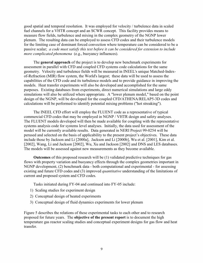
Estimates of the magnitudes of the governing parameters for a hypothetical pressurized cooldown (LOFA) were also developed. Paul Bayless of INEEL provided predictions of this transient from a typical systems code (Athena) and appropriate parameters were calculated from their definitions. Resulting predictions of the Reynolds number variation (non-dimensional flow rate) for three locations each in the inner, middle and outer core rings are shown in Figure 12. In this figure a positive sign corresponds to downflow as in full power operation. One sees that in this scenario the Reynolds number decreases to below 2000 within about sixty seconds and then remains below an absolute value of about 500, indicating that laminar flow would be likely. Flow is predicted to become upwards in the inner and middle rings and to remain downward in the outer ring; heat transfer may be to or from the gas, depending on location and timing.
20
During the initial transient, the turbulent criteria are all predicted to remain below their thresholds for significant effects -- as in normal steady operations.
-1 10 4
0
1 10 4
2 10 4
3 10 4
4 10 4
5 10 4
0 10 20 30 40 50 60
Time (sec)
Re
-1000
-500
0
500
1000
2000 4000 6000 8000 10000 12000 14000
Time (sec)
Re
Positive = downflow
G/R-innerG/R-midG/R-outer
Fig. 12. Estimated flow rate trends during a hypothetical pressurized cooldown (LOFA) in a typical NGNP concept.
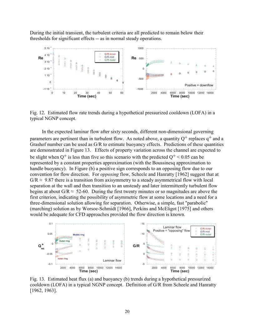
In the expected laminar flow after sixty seconds, different non-dimensional governing parameters are pertinent than in turbulent flow. As noted above, a quantity Q+ replaces q+ and a Grashof number can be used as G/R to estimate buoyancy effects. Predictions of these quantities are demonstrated in Figure 13. Effects of property variation across the channel are expected to be slight when Q+ is less than five so this scenario with the predicted Q+ < 0.05 can be represented by a constant properties approximation (with the Boussinesq approximation to handle buoyancy). In Figure (b) a positive sign corresponds to an opposing flow due to our convention for flow direction. For opposing flow, Scheele and Hanratty [1962] suggest that at G/R ≈ 9.87 there is a transition from axisymmetry to a steady asymmetrical flow with local separation at the wall and then transition to an unsteady and later intermittently turbulent flow begins at about G/R ≈ 52-60. During the first twenty minutes or so magnitudes are above the first criterion, indicating the possibility of asymmetric flow at some locations and a need for a three-dimensional solution allowing for separation. Otherwise, a simple, fast "parabolic" (marching) solution as by Worsoe-Schmidt [1966], Perkins and McEligot [1975] and others would be adequate for CFD approaches provided the flow direction is known.
-0.1
-0.05
0
0.05
0.1
2000 4000 6000 8000 10000 12000 14000
Time (sec)
QWS
+
Outer ring
Inner ring
Middle ring
Laminar flow-5
0
5
10
15
2000 4000 6000 8000 10000 12000 14000
G/R-innerG/R-midG/R-outer
Time (sec)
Laminar flowPositive = "opposing" flow
G/R
Fig. 13. Estimated heat flux (a) and buoyancy (b) trends during a hypothetical pressurized cooldown (LOFA) in a typical NGNP concept. Definition of G/R from Scheele and Hanratty [1962, 1963].

21
In summary, for cooling channels of the NGNP concept chosen for the Point Design [MacDonald et al., 2003], during normal operations at full and reduced power, buoyancy and streamwise acceleration effects are not expected to be significant. During the long-term natural circulation in a pressurized cooldown, property variation is not expected to be significant but buoyancy influences should be observable and the resulting instability might be sufficient to cause an asymmetric, separating low which could be a challenge to predict properly.
Lower plenum ("hot streaking" issue)
As is evident in Figure 3, the hot flow from the coolant channels through the lower plenum to the hot core outlet duct encounters a very complicated geometry. Figure 14 demonstrates some of the details via a plan view. Flow from the coolant channels is brought to the corners of the lower reflector blocks supporting the active core. At these corners short ducts carry the flow vertically down into the plenum where it emerges as hot jets. The cross sections and flow rates of these ducts differ depending on whether the corners -- at which they are located -- are common to three, two or one active column. The temperatures of these jets will vary spatially due to variations in the local fission rate in the core and material histories. In the plenum, circular graphite posts support the active core and the inner and outer reflector columns; differing diameters of these posts lead to differing pitch-to-diameter ratios in the array of posts.
Fig. 14 Typical geometry of the lower plenum in an NGNP concept, showing locations of support posts, support blocks, etc.
The flow in the lower plenum can locally be considered to be a situation of multiple buoyant jets into a confined density-stratified crossflow -- with obstructions. Since the flow converges ultimately to a single outlet, the hot jets encounter different crossflow velocities depending on their locations relative to the outlet. The jets furthest from the outlet essentially exhaust into stagnant surroundings between the adjacent posts with the exception of the flow which they induce and some leakage flow. These furthest jets become wall jets (along the corner

22
formed by prismatic outer reflector support blocks) that then impinge on the floor of the plenum. On the other hand, the last row of jets before the outlet encounters crossflow from all the other jets. Figure 15 illustrates this complicated situation via predictions from a CFD model of flow in the lower plenum of a General Atomics GT-MHR reactor [Schultz and Schowalter, 2004]. Further complicating matters are (1) "slot"-type jets from the spaces along the sides of the hexagonal columns in both the reflectors and active core and (2) leakage of cooler gas through the ducts connecting the Shutdown Cooling System Module (Figure 1) to the center of the lower plenum.
Fig. 15. CFD predictions of flow paths and temperatures in a computer model of the lower plenum of a GT-MHR (courtesy of General Atomics Co).
As indicated in Figure 3, if a "hot channel" region is exhausted via one of the furthest jets, there is concern that its impingement on the floor of the lower plenum may be too hot for the insulation layer protecting the metallic Core Support Plate below. The "hot streaking" issue pertains primarily to the entrance of the hot outlet duct to the turbomachinery. If a "hot channel" region exhausts through one of the last jets before the outlet duct, there is concern that it may not mix (and thereby cool) sufficiently before flowing along the metallic outlet duct.
To assess CFD codes and their turbulence models for their capabilities to handle lower plenum flows and mixing, one needs measurements (and predictions) of the temperature, velocity components and Reynolds stresses as functions of the three dimensions involved, heat transfer coefficients and wall shear stresses along the surfaces and the non-dimensional frequency of any possible eddy shedding from the posts. For systems or integral codes, if feasible (for example, well-mixed conditions), comparable integral quantities and loss coefficients are desired.
For the lower plenum, the solutions for flow and mixing are determined by the geometry, by the non-dimensional parameters appearing in the governing equations and by the inlet and boundary conditions. For equivalent shapes, the geometry can be represented by ratios of appropriate length scales such as pitch-to-diameter p/Dp for the support posts. In an idealized plenum, additional length scales include the jet hole diameter Dj and the height H of the plenum;

23
so, for scaling, the ratios Dj/Dp and H/Dp or related quantities (such as H/Dj) should be preserved as well. If the flow from the jets were uniform, a governing overall Reynolds number could be defined in terms of the gas mass flow rate, one of the length scales and the gas viscosity at the entering (jet) temperature. A number of Reynolds numbers can be defined, such as jet Reynolds numbers Rej, post Reynolds numbers Rep, plenum Reynolds numbers based on a hydraulic diameter ReDh, Reynolds numbers based on the minimum free-flow area as in heat exchangers [Kays and London, 1955], etc. However, for the idealized overall case, once one Reynolds number is fixed all the others are determined since the various geometric ratios are fixed. To subdivide the problem into characteristic local regions, separate "inlets" are considered -- such as a jet inlet duct and a plenum cross flow -- thereby introducing two independent Reynolds numbers as governing parameters to be preserved in the scaling (e.g., Rej and ReDh). For "compressed" gases, a Mach number M or an Eckert number could be required as a scaling parameter; however, if M is less than about 0.3, the gas can be considered to be "non-compressed" and the compressibility effects can be neglected (i.e., it behaves as an incompressible fluid with ∆p/p << 1).
Heat transfer or differences in temperature introduce additional governing parameters. The Prandtl number occurs in the thermal energy equation but for helium and other common gases, its variation is slight. Temperature variation can affect the gas density if the variation is sufficiently large and, thereby, introduce buoyancy influences. If the buoyancy effects are "large" relative to thermal mixing or diffusion, the flow may stratify with the hotter gas remaining near the upper surface of the plenum and preferentially impinging on the upper surface of the metal outlet duct. An overall Richardson number Ri = g(ρ2 - ρ1)H / (ρ1Vb2) can be defined and be evaluated to investigate the likelihood of stratification and importance of buoyancy. (The Richardson number can loosely be considered to relate buoyancy effects to viscous effects, e.g., forces or related frequencies depending on the specific Ri definition.) Or a jet Richardson number can be evaluated for examining the expected behavior of a hot jet injected into a stratified cross flow (without posts). Gradient Richardson numbers are utilized to treat pointwise buoyant effects but they typically cannot be predicted in advance and, therefore, become dependent variables rather than controlling parameters.
Jets in cross flows are typically characterized by velocity ratios, such as Vj/Vp, or mass or momentum flux ratios. Knowing one of these ratios and the gas properties, one can calculate the others as appropriate for comparison to other studies. As implied above, these ratios will vary significantly from one side of a lower plenum to the other as the jet inflow remains approximately the same magnitude and the crossflow increases as more and more jets interact.
The near-field behavior of a jet is dependent on its entering profiles of mean velocity and turbulence quantities. These variables are in turn dependent on the geometry of the duct in which this entering flow develops. Many (most?) experiments on free jets, impinging jets and wall jets have been conducted with orifices or flow nozzles to form uniform, non-turbulent entering jet profiles. Consequently, classical wisdom and textbook descriptions for jet characteristics are not necessarily valid for the near-field mixing of jets in industrial applications such as an NGNP flow geometry (Figure 16). Few studies of impinging jets have utilized fully-developed turbulent flows for the jet inlet [Cooper et al., 1993; Condie, McCreery and McEligot, 2001]. Figures 6 and 16 show that the flow transitions from cooling channels to lower

24
plenums in typical gas-cooled reactors involve short ducts. For example, in the GT-MHR design shown in Figure 16, the jet entry duct is only about four diameters long with its inflow conditions being dependent on the Reynolds numbers of the flows from the cooling channels; the resulting jet entry profile is not likely uniform nor fully-developed.
To obtain insight into the phenomena expected in the lower plenum of an NGNP concept, some of the non-dimensional parameters have been estimated for normal operation at a full power of 600 MWth. Approximate nominal conditions have been employed so the reader should consider the values to be only order-of-magnitude estimates. Geometric ratios below the active core are
Dj/Dp ≈ 0.7, p/Dp ≈ 1.7 and H/Dp ≈ 7
For a single-hole "corner channel" (i.e., the duct along the corner of a single active outer column with two inactive solid columns adjacent), the bulk velocity at 1000 C is about 25 m/sec (80 ft/sec) and the resulting jet Reynolds number is about 90,000. Due to the high sound speed of helium, the Mach number is about 0.01 so the flow can be considered to be "non-compressed." For corner channels formed at two and three active columns (say two- and three-hole), the mass flow rate and cross sectional area increase proportionately but the hydraulic diameter does not. The plenum flow at the far side away from the outlet duct goes from two single-hole jets then between solid supporting blocks and supporting posts towards the first two-hole jet. At this location the horizontal bulk velocity in the plenum is about 0.4 m/sec (1.4 ft/sec), giving Vj/Vp ≈ 50 so jet penetration into the cross flow is expected to be high. One might expect these jets to travel along the adjacent solid vertical corner as wall jets and then to impinge on the plenum floor. A plenum Reynolds number at the passage between the first row of posts encountered would be about 24,000, based on the hydraulic diameter of the opening.
Comparable estimates may be made for the other extreme, the region near the exit to the outlet duct. For the flow between the row of posts before the last row of jets, the plenum bulk velocity would be about 40 m/sec (130 ft/sec), still a low Mach number. The jet-to-crossflow velocity ratio would be about 0.6, more in the range of typical crossflow experiments such as those by Ramsey and Goldstein [1971] and Andreopoulos and Rodi [1984]. Even without buoyancy effects (if the jet is hot relative to the crossflow) and drag by nearby posts, the jet penetration would be expected to be less than two jet diameters which would be less than a fifth
20c
cDL ≅
4j
sDL ≅
10jD
s ≅
4.1jr
r ≅
7pD
H ≅ jV
pV
Fig. 16. Schematic diagram of geometric transition from coolant channels to jet in lower plenum for a typical NGNP concept (GT-MHR precursor).

25
of the distance to the plenum floor. The plenum Reynolds number in this region would be about 3 x 10⁶.
In operation at reduced power, the flow rates, velocities and Reynolds numbers would be reduced proportionately but the velocity ratios would remain the same. Thus, at ten per cent power, the plenum Reynolds number for flow between the first row of posts would be of the order of 2400; the convergence between these posts may induce a tendency towards laminarization there at this Reynolds number [Chambers, Murphy and McEligot, 1983] but most of the plenum could be expected to have turbulent flow. If the temperature differences from hot channels are approximately the same at reduced power, buoyancy effects could become more significant.
Approximate analyses were conducted to examine whether significant influences of buoyancy should be expected for the jets entering the lower plenum and for the near horizontal flow within it. Nominal operating conditions were considered. A crude analysis -- for the height H a column of buoyant gas would have to be in order to balance the momentum flow rate coming from a jet -- led to the approximation that (H/Dj) is given by a Froude number Frj (= (Vj2)/[g ((Tj/T∞) - 1) Dj]) based on jet diameter Dj. If Frj >> 1, it would be expected to be effectively a
momentum-driven jet. For a 300 C temperature difference and T∞ = 1000 C, the approximations give Frj ≈ 2800 at full power and about 28 at one-tenth power, both cases indicate domination by the jet momentum flow rate. That is, buoyancy would not be expected to have a significant influence on the jet interaction with the flow in the plenum.
A second approximate analysis was conducted to estimate when a temperature gradient will be likely to stabilize a horizontal turbulent channel flow, thereby leading to reduced thermal transport near the upper surface. For the lower plenum this situation probably would be a pessimistic estimate since one expects turbulence from the jets and flow around the posts to counter the stabilizing influence of buoyancy. Gage and Reid [1968; Turner, 1973] found that for pointwise gradient Richardson numbers Ri greater than about 0.0554 the flow is stable for all Reynolds numbers. For turbulent wall flows, the highest temperature (density) gradients occur at the wall so the highest gradient Ri values may be there or nearby. Therefore, we defined
Riwall = - gβ(∂T/∂z)wall/((∂U/∂z)wall)2
to characterize this situation - and we hypothesize that it can be used as an order-of-magnitude measure to indicate whether we need to worry about flow stabilization or "laminarization" by buoyancy. For fully-established flow of a gas, one can approximate this parameter as
Riwall ≈ 13.5 Rio Pr0.4 / Re0.7
where Rio is an overall Richardson number defined as g(Thot - Tcold)H/(2 Tbulk Ubulk2).
We suggest that, if Riwall << 0.05, then the flow is probably well-mixed and buoyancy effects are negligible. If Riwall is about 0.05 or greater, then we should worry about buoyancy

26
effects and try to treat them. For nominal full power conditions and Thot - Tcold = 100 C, one may estimate Riwall ≈ 0.015 (probably "well-mixed") in the region of the plenum away from its outlet. For the same temperatures near the outlet, Riwall ≈ 7 x 10(-8). At one-tenth power, Riwall ≈ 7.7 (stabilizing) away from the outlet and Riwall ≈ 4 x 10(-5) near the outlet (well-mixed). Consequently, our preliminary conclusions are that
• for full power, buoyancy influences are probably not important
• for reduced power (ten per cent), buoyancy probably is important at the side of the lower plenum away from the outlet but not near the outlet.
Thus, experiments without buoyancy effects (as in those proposed for the INEEL Matched-Index-of-Refraction flow system) should provide useful benchmark data for assessing CFD codes for some lower plenum flows, particularly at normal full power. Likewise, in those cases the turbulence models in the CFD codes should not need to incorporate buoyancy influences.
The acceleration parameter, Kv = ν(dVb/dx)/Vb2, was estimated for the convergence into the hot outlet duct from the lower plenum. For nominal full power operation, the estimates give Kv ≈ 5 x 10(-7), about the order-of-magnitude of the threshold for reduction of turbulence in a turbulent boundary layer. At a reduced power of ten per cent, Kv would increase by a factor of ten to about 5 x 10(-6). Laminarization is expected to occur at about 3 x 10(-6) and above so it would be probable in this case as in some rocket nozzles and turbine blade passages. In this case, laminarization would be expected to reduce the heat transfer rate to the surfaces of the hot outlet duct but might worsen the "pattern factor" of the flow into the turbomachinery.
In summary, the flow within the vertical ducts to the lower plenum is expected to be turbulent as is the horizontal crossflow in the plenum. The velocity ratio of the resulting jets Vj/Vp will range from about 1/2 to fifty; these jets will be momentum-driven with negligible buoyancy influences. At reduced power, laminarization or buoyancy-induced stabilization may be possible in some regions of the lower plenum.
Experimental needs
The thermal hydraulic needs for assessment of codes for the NGNP Point Design have been determined in the above section on "Scaling studies for experiment design." Once the appropriate non-dimensional parameters are identified and their magnitudes are evaluated, the question becomes whether useful benchmark data are already available in the ranges covered by NGNP operations. So existing experimental knowledge must be reviewed to see if there are any gaps in the required knowledge. The gaps identified can be considered to describe further experiments necessary to permit assessment over the full range of possible operating conditions. The purpose of this section is to accomplish those determinations for the heated vertical tube ("hot channel" issue) and the lower plenum ("hot streaking" issue).

27
Heated vertical tube
For summaries of studies on the effects of property variation on turbulent and laminar internal gas, the reader is referred to a review by McEligot [1986] (as well as the earlier one by Petukhov [1970]). While not all-inclusive and concentrating primarily on forced convection, this review can provide useful introductions to the subject. Reviews of mixed convection in vertical tubes are presented by Jackson and coworkers [Jackson, Cotton and Axcell, 1989; Cotton and Kirwin, 1995]. Useful reviews of the status of numerical prediction techniques for turbulent flows have been published by Nagano and Shimada [1995], Iacovides and Launder [1995] and Hanjalic [1999]. The reader is referred to these reviews for general background on computational fluid dynamics (CFD).
Herwig and colleagues have developed asymptotic analyses using linear perturbations to account for fluid property variation in heated, "fully-developed" forced laminar flow in pipes and annuli at moderate heat fluxes [Herwig, 1985; Herwig and Klemp, 1988; Herwig, Voigt and Bauhaus, 1989]. Their results can be expressed in terms of power laws of property ratios; then, if the properties can be represented as having power law dependencies on the absolute temperature as in the section on scaling above, they can be converted to a "temperature ratio method" [Kays, 1966]. Comparable approaches for turbulent flow are presented by Gersten and Herwig [1992].
Numerical predictions for the effects of gas property variations on developing laminar flows in vertical circular tubes were derived by Worsoe-Schmidt and Leppert [1965] and were extended by Bankston and McEligot [1970]. The former study included some treatment of buoyancy effects. The latter paper provided explanation of an apparent discrepancy between measured and predicted friction factors. For dominant forced convection and constant wall heat flux, McEligot and Swearingen [1966] developed approximate correlations of Worsoe-Schmidt's laminar analysis to account for effects of gas property variation in a circular tube. Bankston derived an approximate superposition method to handle property variation in applications to gas-cooled nuclear reactors for laminar or turbulent flows [Bankston and McEligot, 1969].
As noted in the scaling studies, some insights into the complicated buoyancy influences were provided by Scheele and Hanratty [1962, 1963]. For well-developed axi-symmetric laminar flow with constant gas properties, several authors [Hallman, 1956; Hanratty, Rosen and Kabel, 1958; Morton, 1960] have derived analytical predictions via the Boussinesq approximation (i.e., density variation only affecting the gravitational body force). Results may be described in terms of the ratio of two dimensionless numbers, G and R, for buoyancy and flow rate, respectively. Effects on the velocity profiles were shown in Figure 9. In contrast to turbulent flow, an "aiding" laminar flow (heated upflow or cooled downflow) enhances heat transfer parameters; an "opposing" flow reduces these parameters until it becomes unstable and undergoes transition to a turbulent-like flow. In aiding flow the Nusselt number is estimated to be enhanced by about ten per cent when |G/R| is approximately twenty and transition is initiated at |G/R| ≈ 35-40 or more. For opposing flow, Scheele and Hanratty suggest that at G/R ≈ 9.87 there is a transition from axi-symmetry to a steady asymmetrical flow with local separation at the wall and then transition to an unsteady and later intermittently turbulent flow begins at about G/R ≈ 52-60. These studies have been extended by more extensive numerical analyses and additional experiments. Useful reviews are included in the papers by Nesreddine, Galanis and

28
Nguyen [1998], Behzadmehr, Galanis and Laneville [2003] and Nguyen et al. [2004]. Yao [1987], Yao and Rogers [1989] and Su and Chung [2000] have conducted further linear stability analyses. Wang, Tsuji and Nagano [1994] and Nesreddine, Galanis and Nguyen [1998] numerically studied effects of axial diffusion in the thermal entrance of vertical tubes. Morton et al. [1989] carried out a numerical study to model their experiment on heated or cooled water flow being forced vertically in a circular plastic tube. Nguyen et al. [2004] examined transient laminar mixed convection of air numerically, using a full 3-D-transient-model and Boussinesq's approximation.
Data for correlations are available for heated gases over wide ranges of parameters but probably not for all conditions needed, even for circular tubes. Whether all-inclusive correlation equations are possible for system safety codes is doubtful due to the number of possible phenomena to be included. Tabular correlations may be needed. For either approach, tabulations of basic measurements are required in appropriate non-dimensional form. In some cases this tabular information is included in journal papers, but more often it is in theses or report form.
For convection to gas flow in a circular tube with property variation, many experiments were conducted during the 1950s and 1960s. Most were with small diameter tubes so forced convection dominated and only integral parameters, such as convective heat transfer coefficients and apparent friction factors, could be determined. NASA Lewis Research Center conducted a number of studies aimed at having high wall-to-bulk temperature ratios for application to regenerative cooling of rocket nozzles, some in the nuclear propulsion program. For application to the gas-cooled nuclear reactor program, McEligot, Magee and Leppert [1965] and McEligot, Ormand and Perkins [1966] measured local heat transfer to helium, nitrogen and air in vertical circular tubes over ranges: 1 < (Tw/Tb) < 4.5 and 1450 < Reinlet < 233,000.
As the Reynolds number is decreased in a typical experiment, the relative heat loss increases, thereby increasing the uncertainty in the deduced heat transfer and friction parameters. To counter this problem, Reynolds, Swearingen and McEligot [1969] mounted their test section in a vacuum chamber (large "bell jar") and calibrated the local thermal emissivity for heat loss determinations. The data for helium at Rein ≈ 4200, 6800 and 10,200 plus air at Rein ≈ 3900 are tabulated in the thesis by Reynolds [1968]. Shumway [1969] provides tabulations of heat transfer to helium in laminar flow at Re ≈ 1770 and 1870. In addition to extensive measurements with helium and hydrogen at high heating rates himself, Maynard F. ("Bud") Taylor from NASA Lewis compiled the data tabulations of many investigators of this topic; whether his compilation is archived anywhere is not clear.
Mikielewicz et al. [2002] demonstrated that many turbulence models used in general purpose CFD codes fail to predict the simplest case correctly for a circular tube: fully-established flow with constant properties (Figure 17). This case should serve as a first test for any turbulence models proposed for heat transfer to the coolant in gas-cooled reactors; in general, models which are inadequate in this situation do poorly at predicting temperatures when fluid properties are varying.
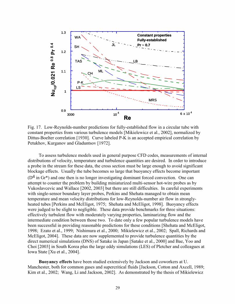
29
0.9
1
3000 6 x 10 4
JL
Constant propertiesFully-es tablishedPr ~ 0.7
WA
1.1
1.2
1.3
Re10
4
LB
S H
MRS
P-K
CH
T AS
ML
LS
0.9
1
3000 6 x 10 4
JL
Constant propertiesFully-es tablishedPr ~ 0.7
WA
1.1
1.2
1.3
Re10
4
LB
S H
MRS
P-K
CH
T AS
ML
LS
Nu c
p/0.
021
Re
0.8
Pr 0.
4
Fig. 17. Low-Reynolds-number predictions for fully-established flow in a circular tube with constant properties from various turbulence models [Mikielewicz et al., 2002], normalized by Dittus-Boelter correlation [1930]. Curve labeled P-K is an accepted empirical correlation by Petukhov, Kurganov and Gladuntsov [1972].
To assess turbulence models used in general purpose CFD codes, measurements of internal distributions of velocity, temperature and turbulence quantities are desired. In order to introduce a probe in the stream for these data, the cross section must be large enough to avoid significant blockage effects. Usually the tube becomes so large that buoyancy effects become important (D4 in Gr*) and one then is no longer investigating dominant forced convection. One can attempt to counter the problem by building miniaturized multi-sensor hot-wire probes as by Vukoslavcevic and Wallace [2002, 2003] but there are still difficulties. In careful experiments with single-sensor boundary layer probes, Perkins and Shehata managed to obtain mean temperature and mean velocity distributions for low-Reynolds-number air flow in strongly-heated tubes [Perkins and McEligot, 1975; Shehata and McEligot, 1998]. Buoyancy effects were judged to be slight to negligible. These data provide benchmarks for three situations: effectively turbulent flow with moderately varying properties, laminarizing flow and the intermediate condition between those two. To date only a few popular turbulence models have been successful in providing reasonable predictions for these conditions [Shehata and McEligot, 1998; Ezato et al., 1999; Nishimura et al., 2000; Mikielewicz et al., 2002; Spall, Richards and McEligot, 2004]. These data are now supplemented to provide turbulence quantities by the direct numerical simulations (DNS) of Satake in Japan [Satake et al., 2000] and Bae, Yoo and Choi [2003] in South Korea plus the large eddy simulations (LES) of Pletcher and colleagues at Iowa State [Xu et al., 2004].
Buoyancy effects have been studied extensively by Jackson and coworkers at U. Manchester, both for common gases and supercritical fluids [Jackson, Cotton and Axcell, 1989; Kim et al., 2002; Wang, Li and Jackson, 2002]. As demonstrated by the thesis of Mikielewicz

30
[1994], data tabulations exist; however, they are not necessarily available in the open literature. Some tabulated data for turbulent flow in a vertical circular tube of 36.3 mm inside diameter are available in the appendices of the monograph by Vilemas and Poskas [1999; Poskas, 2004]. Their ranges of investigation covered 3750 < Rein < 35,000, Gr* < 9 x 10⁸ and q+ < 0.0034 as well as helical and curved channels. Since their test section employed a bell-mouth entrance which would give a delayed transition to turbulent flow as the Reynolds number is increased, the low-Reynolds-number data of Vilemas and Poskas are not likely to be representative of tube flow in an NGNP design.
To assess correlations of integral heat transfer and friction parameters and for preliminary assessment of turbulence models (Figures 17 and 18), measurements of wall temperatures and pressure drops suffice. As indicated above, turbulence modelers desire data on internal distributions of turbulence quantities for their models; in general, these quantities have not been measured well with significant gas property variation. There are some careful measurements of internal mean temperature and streamwise velocity distributions which can be used for further intermediate assessment. In either case, to be useful, benchmark data need to be available in tabular form and their conditions and estimated experimental uncertainties [Kline and McLintock, 1953] need to be known. To date, the authors have found such data in the experiments listed in Table 1; the ranges of these data are depicted in Figure 19 as regime maps for Re, q+ and Bo*. Most are for dominant forced convection; however, some comparable data are known to exist for mixed convection (e.g., Prof. Jackson and his colleagues) but tabulations are not yet in hand. Additional data, including internal profiles, are presented in graphical form in some references so they might be digitized for use -- provided the boundary conditions and estimated experimental uncertainties are known well.
Twall (K)
Shehata
v f
Fig. 18. Preliminary assessment of turbulence models via wall temperature data of Shehata [Shehata and McEligot, 1998; Richards, Spall and McEligot, 2004]

31
Table 1. Tabulated benchmark data available Measurements Authors Gas
Tw{x} P{x} T{x,r} U{x,r} McEligot [1963] He, N2, air X X Reynolds [1968] He, air X Shumway [1969] He X X Perkins [1975] Air X X X Shehata and McEligot [1995] Air X X X X Vilemas and Poskas [1999] Air X
0.0001
0.001
0.01
10 4 10 5 10 6
Re
q +
Heat flux parameter
1500
Neg
ligib
le
Data of McEligot ( , ) and colleagues ( , , ) and of Vilemas and Poskas ( )
Neg
ligib
le
Some internal velocity and temperature data but not turbulence distributions
ReData of McEligot ( , ) and colleagues ( , , ) and of Vilemas and Poskas ( )
Fig. 19. Conditions for which tabulated internal gas heat transfer (and some friction) data are available.
For accident scenarios involving air ingress, the heavier air is hypothesized to displace the helium used as the normal working fluid. Melese and Katz [1984] have shown that replacement of helium by a heavier gas improves the natural circulation performance of the cycle. However, a consequence of displacement process will be a mixture of the two gases in some components.
As the concentration of a gas mixture changes, so do its properties. It is known, but apparently not well, that the variation of thermal conductivity and specific heat versus concentration can lead to a minimum in the Prandtl number at an intermediate concentration. Figure 20 provides an example of this behavior for a mixture of helium and argon, which has a molal mass a bit heavier than air (40 versus 29). Seeing a value of the Prandtl number appear between liquid metals and common gases leads one to question the applicability of typical correlations and turbulence models.
Experiments and numerical analyses have been conducted at U. Arizona and INEEL. The gases were considered to be completely mixed. With small flow channels, the thermal behavior locally in the channel can be dominant forced convection even though the overall circulation is induced by buoyancy differences. Therefore these studies concentrated on forced convection.

32
For application to regenerative heat exchangers (which could be plate-fin configurations) as in the NGNP Point Design, McEligot, Taylor and Durst [1977] numerically examined heat transfer to laminar flows between parallel plates over a range 0.2 < Pr < 2/3. Correlations were developed for heat transfer and wall friction.
Fig. 20. Effect of concentration on Prandtl number for helium-argon mixtures [Pickett, Taylor and McEligot, 1979].
Experiments in small circular tubes covered the ranges 0.18 < Pr < 0.72 and Re ≈ 34,000, 60,000 and 84,000, i.e., high-Reynolds-number turbulent flow [Taylor, Bauer and McEligot, 1988]. Effects of gas property variation with temperature were examined as well as the constant property asymptote. Comparing these data to numerical predictions including information from direct numerical predictions, McEligot and Taylor [1996] were able to evaluate models hypothesized for the distribution of the turbulent Prandtl number often used in turbulence modeling in popular CFD codes.
For turbulent flow at low Prandtl numbers, the popular Colburn analogy and Dittus-Boelter correlation, based on data for Pr > ~ 0.7, seriously overpredict Nusselt numbers for fully-established conditions with constant properties in the range of mixtures covered. The correlations of Kays and of Petukhov fared better. For computations, predictions using Reynolds analogy in conjunction with a simple van Driest turbulence model agreed with downstream measurements to within about five per cent, which should be adequate for most thermal designs.
For quasi-established turbulent flow of mixtures at "high" Reynolds numbers in dominant forced convection, wall temperatures can be predicted reasonably by a correlation such as

33
Nub ≈ 0.023 Reb0.8 Prb0.65 (Tw/Tb)-a
where
a = 0.57 - 1.59 / (x/D) [Taylor, Bauer and McEligot, 1988]. For steady laminar flow at moderate Reynolds numbers, the governing equations can be approximated by a parabolic system of partial differential equations. Consequently, good solutions can be obtained quickly by an efficient "marching" technique, as by Bankston and McEligot [1970], and experiments are not needed provided the important phenomena are included in the formulation. Thus, for gas mixtures, measurements of heat transfer to helium-air mixtures are likely only needed for low-Reynolds-number turbulent flow in mixed convection and dominant forced convection.
In summary, it appears that sufficient benchmark data are available to assess correlations for systems codes for the ranges of expected normal operating conditions in the coolant channels of the prismatic NGNP Point Designs. Further measurements may be needed to cover possible ranges of hypothesized accident scenarios and for detailed pointwise assessment of proposed turbulence models for CFD codes.
Lower plenum
The flow in the lower plenum can locally be considered to be a situation of multiple buoyant jets into a confined density-stratified crossflow -- with obstructions. While -- to the authors's knowledge -- no benchmark experiments are available that treat all complicated lower plenum phenomena together, many studies have been conducted for individual phenomena separately. King [2004] of Oregon State has surveyed available literature and has compiled lists of pertinent studies for the following related situations:
• Flow through tube bundles
• A single jet in an unconfined crossflow
• Multiple parallel jets in a stagnant environment
• Multiple jets in an unconfined crossflow
• A single jet in a confined crossflow
• Multiple jets in a confined crossflow
The references and investigators that King identified can provide significant tests of codes and their turbulence models for a wide variety of flow and mixing phenomena occurring in a lower plenum.

34
King concluded that it has typically been found that the anisotropy of the turbulence in these situations leads to an inability of popular k-ε turbulence models to predict the proper scalar mixing. Thus, the k-ε model likely cannot be used if good accuracy is desired. However, for approximate results and qualitative insight, this model might be employed with the realization that it can be expected to underestimate the turbulent mixing. It is believed that this underestimation will give conservative results in the context of the "hot streaking" issue of the NGNP lower plenum.
King suggests that further benchmark experiments on
• Scalar mixing in a tube bank
• Single jet in a confined crossflow
• Multiple jets in a confined crossflow and
• Multiple jets in an unconfined crossflow
would be desirable for assessment of CFD codes predicting turbulent mixing for lower plenum applications. He recommends that simultaneous LDA (laser Doppler anemometry) and PLIF (planar laser-induced fluorescence) measurements of turbulent velocity and scalar fluctuations be made so that turbulent scalar transport terms, such as u′c′ or u′t′, can be deduced for comparison to model predictions.
The literature on heat transfer and flow of impinging jets is vast and growing [Martin, 1977; Downs and James, 1987; Hrycak, 1981; Webb and Ma, 1995; Ma et al., 1997; Lee and Lee, 2000]. The primary application has been for enhancement of convective heat transfer parameters [Gardon and Akfirat, 1965] so much of the literature concentrated on integral heat transfer quantities, such as local or average heat transfer coefficients (e.g., Goldstein and Behbahani [1982], Hrycak [1983], Baughn and Shimizu [1989], Liu and Lienhard [1993], San, Huang and Shu [1997], Ma et al. [1997], Siba et al. [1998], Lee and Lee [2000]). Numerical predictions are provided by Wolfstein [1970], Rubel [1980], Huang, Mujumdar and Douglas [1984], Amano and Brandt [1984], Craft, Graham and Launder [1993], Dianat, Fairweather and Jones [1996], Heyerichs and Pollard [1996], Lee et al. [1997], Olsson and Fuchs [1998], Satake and Kunugi [1998], Craft [1998], Morris, Garimella and Fitzgerald [1999], Parneix, Behnia and Durbin [1999], Behnia et al. [1999] and others. To maintain effectiveness, often arrays of impinging jets are employed with small pitch-to-diameter spacings, so the non-dimensional radial extent is not large [Womac, Incropera and Ramadyani, 1994; Slayzak, Viskanta and Incropera, 1994; Lienhard et al., 1996]. For gas turbine cooling [Simon et al., 1999], the jet is formed by passage through a short orifice passage so the initial velocity profile of the jet is near uniform; this uniform profile is typical of many experiments where the jet is formed from a converging nozzle and of many numerical predictions.
Condie, McCreery and McEligot [2001] summarized the fluid physics references found for simple axisymmetric impinging jets in general. With the exception of the outflow study of Moller [1963], the jets from fully-developed flows were measured in semi-infinite surroundings [Cooper et al., 1993; Kim, Wiedner and Camci, 1995; Lee and Lee, 2000]. The early studies of

35
confined flows, such as those of Kreith and colleagues [1963, 1965], concentrated on the outflow at large distances from the impinging jet.
At Rej ≈ 2500, Nelson [1987] employed an LDV to obtain phase-averaged velocity measurements to map coherent spatial characteristics of a flow from a nozzle four diameters above the plate. Landreth and Adrian [1990] used particle image velocimetry to obtain instantaneous velocity fields and averaged quantities for a jet at Rej ≈ 6600 situated four diameters above their plate; however, their field extended only about two diameters from the centerline. Cooper et al. [1993] conducted a relatively wide range of measurements focusing on data from a long tube to assist turbulence modeling. At Rej = 2.3 x 10⁴ and 7 x 10⁴, they obtained data for a jet located two to ten diameters above the plate to a radius of about eight diameters from the centerline. Results include mean and fluctuating velocities and turbulent shear stresses. They comment that, while the topic has been the subject of many experiments, none could have been said to have been designed with the needs of turbulence modeling in mind. Usually the flow conditions at the nozzle exit are insufficiently prescribed or too far above the plate to be useful. Even for confined jets, only Fitzgerald and Garimella [1996] appear to have measured turbulence quantities outside the impinging jet and its wall jet; they present rms radial velocity fluctuations, primarily in and near the wall jet at high Reynolds numbers. Emphasis on the region outside the wall jet is lacking in their study.
Numerical studies show that impinging jet flows are difficult to predict reliably. Craft, Graham and Launder [1993] attempted four turbulence models -- one k-ε model and three second-moment closures -- and found none to be entirely successful. Morris, Garimella and Fitzgerald [1999] showed a standard high-Re k-ε model and an RNG k-ε model to be inferior to a Reynolds stress approach. Behnia et al. [1999] indicated that the flow characteristics at the jet inlet strongly affect the heat transfer rate (so the use of the appropriate jet velocity profile is important for applications). Advanced numerical techniques are beginning to be employed. Olsson and Fuchs [1998] studied the use of large eddy simulations (LES), examining the effects of spatial resolution and different sub-grid-scale models. Satake and Kunugi [1998] extended an axi-symmetric direct numerical simulation (DNS) technique to treat approximately the confined jet flow experiment of Nishino et al. [1996] at a Reynolds number near 10,000. Provided spatial resolution is adequate, DNS can be a means to avoid problems with turbulence modeling but computational requirements are extensive even for low-Reynolds-number flows.
The interactions between buoyant jets and crossflows have been studied by Campbell and Schetz [1973], Wright [1984], Zhang and Ghoniem [1994], Hwang, Chiang and Yang [1995], Huq [1997], Hunt, Cooper and Linden [2001] and Jirka [2004]. Wright gives a useful treatment of the various associated length scales.
Heat transfer and friction parameters for cross flow through bundles have been available for many years for a wide range of arrays [Grimison, 1937; Kays and London, 1955; Zukauskas, 1972]. Pressure drop and local heat transfer coefficients were obtained by Achenbach [1989] for staggered tube bundles at high Reynolds numbers. Velichko, Pronin and Yassin [1993] measured heat transfer and friction parameters for non-traditional tube bundle arrangements. Stanescu, Fowler and Bejan [1996] determined optimal spacing of the cylinders to maximize the average heat transfer conductance for an entire bundle. Barsamian and Hassan [1996] have

36
applied large eddy simulation (LES) to spatially-periodic flow across a tube bundle at Re ≈ 1.7 x 10⁵; fluctuating lift and drag spectra were calculated and compared to the limited data available [Chen and Jendrzejczyk, 1987]. Mean and fluctuating velocity components were measured at 2 x 10⁵ < Re < 2 x 10⁶ by Poskas and Survila [1983] for staggered and in-line bundles of tubes. Katinas et al. [1990] measured tube vibrations induced at turbulence levels from one to twelve per cent in the upstream flow to staggered and in-line tubes; although the Reynolds number supposedly was varied from 103 to 2 x 10⁵, effects were not presented in terms of Reynolds number. Fluctuations of heat transfer and velocity have been measured in a staggered tube array by Scholten and Murray [1998]. Beale and Spalding [1998] numerically predicted laminar flow and heat transfer across a variety of tube bundle geometries. Watterson et al. [1999] applied a low-Reynolds-number k-ε model to flow around an array of staggered tubes. A k-ε model was also applied by Wilson and Bassiouny [2000] to predict the laminar and turbulent flow of air across tube banks with apparently satisfactory agreement to data.
Turner [1973] has provided some insight concerning instability of horizontal flows. Thorpe [1987] has reviewed transitional phenomena and development of turbulence in stratified fluids for oceanographic applications. Gage and Reid [1968; Turner, 1973] found that for pointwise gradient Richardson numbers Ri greater than about 0.0554 a horizontal laminar flow is stable for all Reynolds numbers. The stabilization of a turbulent flow by heating from above does not seem to have been examined extensively. Townsend [1957] employed the wind tunnel data of Nicholl [1970] to support an analytical treatment; he concluded that there is an upper limit of 0.5 on the flux Richardson number and of about 0.08 on an "ordinary" Richardson number beyond which a collapse of turbulent motion would occur. A related problem of flow into an open-ended cavity with a heated upper plate has been addressed experimentally by Guidotti et al. [2000].
In addition to the suggestions of King [2004], experiments are needed for the combined features of the lower plenum flows. In particular, missing from the typical jet experiments are interactions with nearby circular posts and with vertical posts in the vicinity of vertical walls - with near stagnant surroundings at one extreme and significant crossflow at the other. The experiments proposed in the present research would address these needs.
In order to obtain further insight into flow phenomena occurring in a lower plenum, a qualitative flow visualization experiment was conducted at INEEL. Jet injection into a region of similar geometry as a section of the NGNP lower plenum was investigated using a simply constructed water flow apparatus. The objective of the experiment was to identify and prioritize flow phenomena, such as jet entrainment, multiple jet interactions, eddy formation, post crossflow and eddy shedding frequency, wall flow effects and overall flow patterns -- for scaling analyses and future experiment design. The simplified study is also useful for identifying features that experiments need to include in more refined designs and for identifying scaling and design problems that need to be resolved or avoided.
The apparatus consists of an acrylic plastic box of rectangular cross-section (Figure 21) with inside dimensions of 73.9 mm (2.91 in.) width by 200 mm (8 in.) length by 175 mm (6.9 in.) height. Support posts are represented by six acrylic tubes of 25.4 mm (1.0 in.) outside diameter --plus one half-tube -- with pitch/diameter ratio equal to 1.71 and height/diameter ratio

37
equal to 6.9, the approximate ratios of the support pedestals in the active core region of the NGNP lower plenum. Flow is injected uniformly into four inlet tubes with 15.7 mm (0.62 in.) inside diameter. The maximum water flow rate through the four tubes (supplied through an inlet plenum connected to a building water spigot) is approximately six gpm. The jet inlet Reynolds numbers are approximately 1280 at the maximum flow rate. The Reynolds number based on the hydraulic diameter of the open channel and total flow rate (i.e., downstream of all four jets) is approximately 3300. Flow visualization is obtained by injecting food coloring dye through a tube connected to a syringe. The injection position may be traversed through the regions of jet injection. Figure 22 shows sequential images of dye injection from three of the four jets.
Flow inlet
Flowoutlet
Posts
Fig. 21. Schematic drawing of apparatus for qualitative flow visualization of lower plenum phenomena away from the outlet duct.
The flow situation simulated corresponds to some aspects of the lower plenum at the far side away from the outlet duct. Phenomena observed in the experiment include jet entrainment of fluid, jet attachment to the upstream wall possibly due to a Coanda effect, eddy formation in the lower and upper upstream corners of the channel, merging of jets, crossflow of fluid around posts and fluid recirculation near the front and rear walls. No indication of periodic eddy shedding downstream of posts was observed. These observations are consistent with the data and observations of Iwaki et al. [2004] who measured velocity fields for crossflow in tube bundles with rectangular and triangular pitches. Periodic eddy shedding was seen for flow in their rectangular geometry but not in the triangular case.
In the present experiment, recirculation of fluid along the front and rear walls was caused by insufficient jet flow near the walls and is not expected to be prototypical. A conceptual sketch of apparent mean streamlines and spreading regions is presented in Figure 23 as our interpretation of the sequential images of Figure 22. The jets were not observed to impinge on the bottom surface before mixing with adjacent jets -- at least partially. This mixing between jets appeared to be enhanced by the flow across the posts. The experiment points to the importance of jet entrainment of fluid on the flow pattern and mixing phenomena.

38
Dye injection in closest jet to wall.
Dye injection in second jet from wall.
Dye injection in third jet from wall
Fig. 22. Sequential images of jet interactions revealed by flow visualization.
Inlet flow
Outletflow
X
Z
Fig. 23. Conceptual interpretation of experimental results presented in Figure 22.

39
Heated flow experiments
As indicated in the section on "Experimental needs," experimental databases are currently available to assess some aspects of the "hot channel" problem. Additional measurements will be obtained in an ongoing project by Prof. L. E. Hochreiter at Penn State and in a current INEEL LDRD project in conjunction with M.I.T. These sources and the existing literature should be compared to the needs identified to determine which additional measurements may be needed for heated gas flow in circular tubes, if any.
Two types of heat transfer experiments will be considered. One would address the "hot channel" problem, if necessary. Conceptually, it will provide documented temperature, velocity and turbulence fields for low-Reynolds-number turbulent, forced and mixed convection (buoyancy effects) and gas property variation in NGNP cooling channels in order to assess codes and their turbulence models at appropriate reactor conditions for which benchmark data are not available. Instrumentation will include miniaturized multi-sensor hot-wire probes developed as tasks in our recent NERI and KNERI projects. Both downflow (normal operation) and upflow ("pressurized cooldown") will considered. The second experiment will treat heated jets entering a model plenum; an apparatus with gas flow will likely be employed for this case. The first year task here is to develop conceptual designs of the apparatuses for these experiments.
Vertical tube
Turbulence modelers request measurements of the basic quantities (dependent variables) of their governing partial differential equations for assessment (and guidance), quantities such as turbulence kinetic energy and Reynolds stresses, v2, u v , etc. These data generally have not been available for strongly-heated internal flows. This part of the study would concentrate on examining the effects of property variation for the geometry of the NGNP Point Design, i.e., a circular tube.
The general goal would be to obtain greater understanding of the structure of strongly-heated, internal, turbulent gas flows, with an emphasis on turbulence structure. Hence, objectives are to measure the fundamental turbulence structure and to obtain benchmark data to assess CTFD codes for high temperature gas flows that are predominantly in the forced convection region, for a range of conditions important in advanced reactors (which may include moderate mixed convection). Conceptually, DNS codes, as by Satake et al. [2000, 2002] and Bae, Yoo and Choi [2003], could accomplish these aims and more; however, DNS calculations must also be compared to time-resolved experimental measurements to insure adequate spatial and temporal resolution, to uncover coding mistakes, to check for prediction of measurable quantities and consistent, useful definitions of those quantities, etc.
The experiment would extend the existing methods of McEligot and Prof. J. M. Wallace of U. Maryland and their colleagues. The probes developed by Profs. Wallace and Vukoslavcevic in a recent KNERI project [McEligot et al., 2002] would be employed at INEEL to measure fluctuating velocity components and temperature in high temperature gas flow through a vertical circular tube for assessment of the predictions and to understand the fundamental effects of this heating on the physics of the flow.

40
While the initial experiments might be conducted using an open flow system incorporating a vertical, resistively-heated, circular test section exhausting directly to the atmosphere in the laboratory as by Shehata and McEligot [1995], the intent would be to develop a more versatile apparatus as shown in Figure 24. The experiment would provide an approximately uniform wall heat flux boundary condition in a tube for helium, either ascending or descending and entering with a fully-developed turbulent velocity profile at a uniform temperature as in coolant channels after passing through an end reflector. Controlled wall heat flux would be provided with a stable electrical power supply. The heated length would be relatively short to permit high heating rates with Inconel as the tube material while approaching quasi-developed conditions. The miniature multiple-sensor hot-wire probes from Prof. Wallace and Vukoslavcevic (Figure 25) would be inserted through the open exit to obtain pointwise temperature and velocity measurements. In general, the experimental methods would follow those of Shehata [Shehata and McEligot, 1995, 1998] except for the extension to the multi-sensor probes from Wallace and Vukoslavcevic and more modern data acquisition equipment.
Vacuum vessel
Multi-sensorhot-wire probe
Thermocouples
Gas circulator
Flow meter
Traversing table
Powersupply
Pressuretransducer
Heat exchanger
Upflow ordownflow
Fig. 24. Potential apparatus to obtain benchmark turbulence data in heated channel flow.
The region controlling the transfer of heat and momentum in turbulent wall flows is primarily the viscous layer which occupies a small fraction of the cross section. This fraction grows as the Reynolds number is lowered. With strong heating, the large turbulent temperature fluctuations make simultaneous measurement of instantaneous temperature and velocity necessary; this situation is the reason for using the multi-sensor probes, but they would be larger than a miniature single-sensor probe. However, if one chooses a large tube and low Reynolds number (for thicker viscous layers) to improve spatial resolution, the problem quickly becomes one of dominant natural convection. The experimenter must compromise in order to obtain data

41
which the theorist can extend to conditions where the experimenter cannot easily tread. In a recent NERI project, preliminary studies with significant buoyancy effects were conducted with a multi-sensor probe by Prof. Vukoslavcevic and Prof. Jackson's colleagues at the University of Manchester (by using large tubes); the test apparatus at INEEL would be developed to avoid significant buoyancy forces except when desired.
Fig. 25. Schematic diagram and front projection of miniature five-sensor probe by Vukoslavcevic and Wallace [2003] for measurement of instantaneous velocity components and temperature; dimensions in millimeters.
The inside diameter of the initial test section at the INEEL would be greater than three cm. (At the INEEL elevation of about 1400 meters, Grashof numbers are about thirty per cent less than they would be at sea level for comparable conditions, allowing slightly larger diameters while avoiding buoyancy effects.) The length of the test section would be chosen to permit measurements through and beyond the normal thermal entry region while attaining significant transport property variation, as exemplified by Tw/Tb and Tw/Ti, with common materials and gas. By employing Inconel 600 for the test section material, maximum surface temperatures of about 1000 C should be possible.
In addition to the usual difficulties of hot wire anemometry, the temperature range of this experiment would involve other problems. High temperature differences between the wall and prongs make thermal radiation to and from the walls an important consideration. The question arises: how to handle gas property variation in the convective heat transfer correlation which serves as the basis for calibration of the sensors? Thermal expansion affects positioning and its measurement. Solutions to these difficulties and others have been developed by Shehata [Shehata and McEligot, 1995] and by Profs. Wallace and Vukoslavcevic in recent NERI and KNERI projects; they would be extended as necessary by these collaborators for use of the multi-sensor probes.
Target operating conditions would be an inlet Reynolds number range from about 2000 to 50,000 based on diameter. Inlet temperature would be 20 to 30 C. Thus, the maximum allowable temperature would permit a temperature ratio Twall/Tin of about 4.3, giving a

42
maximum viscosity ratio µw/µin of about 2.8 for common gases, i.e., significant property variation. The proposed multi-sensor probes would give meaningful measurements of turbulence structure in the viscous layer.
Development of a variable pressure, closed helium flow loop is the recommended approach to extend the range of meaningful data (e.g., larger diameter tube with lower Grashof numbers). For useful measurements in the viscous layer one needs good spatial resolution which may be achieved by having the sensor volume small compared to the viscous layer, say d+probe << 30. Thus, the tube must be much larger than the size of the probe. Prof. Jackson has developed a criterion that a buoyancy number defined as Bo = Gr*/(Re3.425Pr0.8) must be small in order to have dominant forced convection [Mikielewicz et al., 2002]. The difficulty with using a large tube diameter is that the Grashof number,
Gr* = g ρ2 D4 q"wall / (µ2 k T)
is strongly dependent on the diameter. Comparing the properties of the desired gas - helium - to air, one finds the viscosities are about the same, kHe is about five times kair and ρHe is about ρair/7 at the same temperature and pressure. These differences help, but the diameter is still a strong factor. Since ρ ≈ p/RT, a possible solution to reduce Gr* and, hence, Bo is to apply the approach of Zagarola and Smits [1998] in reverse. They used high pressures to obtain high densities and consequently achieved their desired high Reynolds numbers. A comparable apparatus with a wind tunnel installed in a pressure vessel is employed by Prof. J. Eaton at Stanford Univ. Our idea is to reduce the pressure of helium sufficiently to compensate for an increase in the diameter of the tubular test section. Figure 24 illustrates the concept of enclosing an experiment like that of Shehata and McEligot in a vacuum vessel with remote operation of the instrumentation and the traversing mechanism for the multi-sensor probe. The characteristics of a non-uniform, hot exit jet could also be determined; the top of the vacuum vessel could be used as a means of providing flow conditions comparable to the thermal fluid phenomena occurring with non-uniform heated, impinging jets, as in the lower plenum of the NGNP Point Design.
Typical results would include time-resolved, pointwise distributions of the mean velocities, U, V, and their Reynolds stress components as well as wall temperature and static pressure distributions for well-defined thermal boundary conditions. The final test matrix would be developed interactively in collaboration with investigators who would be conducting the related numerical analyses. Throughout the experimental phase, the resulting data would be provided to these collaborators as soon as they become available.
For accident scenarios involving air ingress, the heavier air is hypothesized to displace the helium used as the normal working fluid. However, a consequence of this displacement process will be a mixture of the two gases in some components. As the concentration of a gas mixture changes, so do its properties. It is known, but apparently not well, that the variation of thermal conductivity and specific heat versus concentration can lead to a minimum in the Prandtl number at an intermediate concentration. Seeing a value of the Prandtl number appear between the

43
values for liquid metals and common gases leads one to question the applicability of typical correlations and turbulence models in these cases.
Separately, a collaborative effort between INEEL and MIT has been initiated to obtain convective heat transfer data related to a gas-cooled fast-spectrum reactor (GFR) with a block-core configuration proposed by MIT. The GFR is similar to the NGNP in its use of helium as a coolant and has similar coolant channel dimensions. Upon completion of experiments at MIT this closed-loop apparatus will be transferred to INEEL. The initial test sections have been designed to study mixed convection with upflow. Since it is a closed-loop, this apparatus will be considered for modification to measure heat transfer and wall friction (pressure drop) for helium-air mixtures in forced and mixed convection. The MIT/INEEL loop would be modified to a configuration comparable to that used by Taylor, Bauer and McEligot [1988] for noble gas mixtures. Experimental procedures employed would also correspond to those of Taylor, Bauer and McEligot. Since the MIT/INEEL experiment is intended for low-Reynolds-number turbulent -- and possibly -- laminar flow, its test section should have lower relative heat losses, reducing experimental uncertainties at low Reynolds numbers. System pressure and test section diameter would be adjusted to provide the necessary range of non-dimensional parameters.
Fig. 26. Schematic diagram of apparatus for possible measurement of heat transfer to helium-air mixtures occurring in air ingestion incidents as by Taylor, Bauer and McEligot [1988].
Lower plenum
The second experiment will treat heated jets entering a model plenum. Two types of conceptual model designs are considered, some using gas flow and some using water. Density differences between hot and cool jets in the design using gas flow are treated by varying gas temperature. Density differences in the water flow apparatus are simulated by varying the density of the injected water by adding soluble material, such as salt to water stored in a reservoir before injection. A scaling analysis indicates that the two methods are equivalent for modeling lower plenum flow.

44
Water flow apparatus One-half of the lower plenum is scaled geometrically (Figure 27). The model incorporates the full number of posts (including half-posts at the center-line wall) and inlet flow channels (Figure 28). Windows are provided along three sides. The bottom surface of the model is also constructed of transparent material. The simulated posts are constructed of thin-wall plastic tubes, which may be filled with water to minimize distortion by refraction through the tube walls (although the index-of refraction of the tube material is not matched, this method provides an undistorted view through the majority of the tube width).
Fig. 27. Plan view of water flow model overlaid upon scale drawing of GT-MHR lower plenum.
Inlet flow tubes (138)
Frontwindow
Window Posts(74 + 7 half cylinders)
Bottom window
Exitflow
Window
Fig. 28. Isometric view of water flow model of lower plenum.
The scale of the model is chosen by assuming that 31.8 mm (1.25 inch) OD tubes represent 211 mm (8.3 inch) OD support posts. The scale is approximately one to seven. Maximum water flow is assumed to be two gpm per jet injection tube or approximately 276 gpm for 138 tubes (outer tubes are smaller and have lower flow rates) for the conceptual model.

45
Flow visualization, PIV and PLIF measurements may be obtained by shining a laser light sheet through one window and observing the illuminated path through another window. The light paths through gaps between the tube rows may be observed as collimated paths by use of a cylindrical mirror. This technique was used in INEL experiments that simulated boron injection into a fuel bundle with triangular pitch [McCreery, McKellar and Stoots, 1993].
Gas flow model design One possible configuration is shown in Figure 29. The posts and lower plenum walls are idealized as cylinders positioned between flat walls. The inlet flow channels are represented by nozzles in the top wall. Hot and cold gases are injected through the nozzles at flow rates and temperatures determined from the scaling analysis.
Outletflow
Traversing hot-wire probe(temperature and velocity)
Thermal imagingcamera
Top View
Jet nozzlen
Side View
X
Y
Z
X
lowtemperature
hightemp.
hightemp.
lowtemp.
lowtemp.
lowtemp.
Outletflow
Fig. 29. Schematic diagram of benchmark experiment to simulate thermal mixing in a lower plenum.
The gas temperature field will be mapped using both a traversing hot-wire probe and a thermal imaging camera. The bottom wall of the apparatus will contain multiple access holes for installing hot-wire probes in various positions. The front wall of the apparatus will consist of a
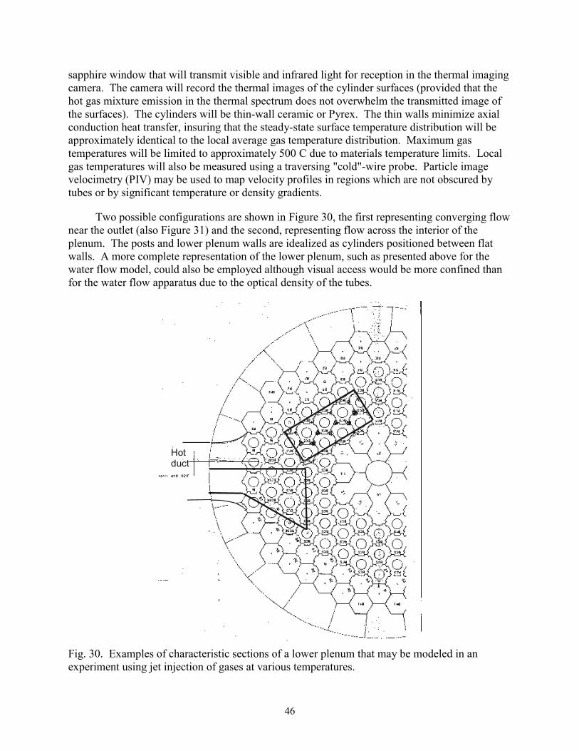
46
sapphire window that will transmit visible and infrared light for reception in the thermal imaging camera. The camera will record the thermal images of the cylinder surfaces (provided that the hot gas mixture emission in the thermal spectrum does not overwhelm the transmitted image of the surfaces). The cylinders will be thin-wall ceramic or Pyrex. The thin walls minimize axial conduction heat transfer, insuring that the steady-state surface temperature distribution will be approximately identical to the local average gas temperature distribution. Maximum gas temperatures will be limited to approximately 500 C due to materials temperature limits. Local gas temperatures will also be measured using a traversing "cold"-wire probe. Particle image velocimetry (PIV) may be used to map velocity profiles in regions which are not obscured by tubes or by significant temperature or density gradients.
Two possible configurations are shown in Figure 30, the first representing converging flow near the outlet (also Figure 31) and the second, representing flow across the interior of the plenum. The posts and lower plenum walls are idealized as cylinders positioned between flat walls. A more complete representation of the lower plenum, such as presented above for the water flow model, could also be employed although visual access would be more confined than for the water flow apparatus due to the optical density of the tubes.
Hotduct
Fig. 30. Examples of characteristic sections of a lower plenum that may be modeled in an experiment using jet injection of gases at various temperatures.
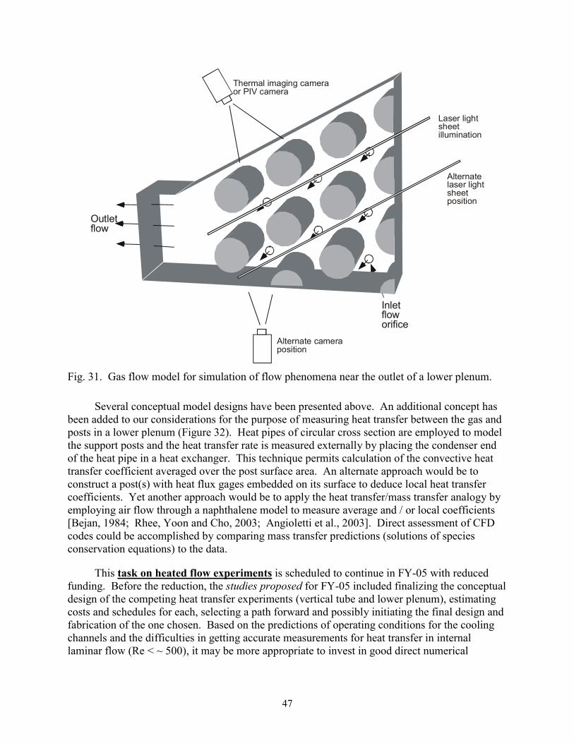
47
Outletflow
Inletfloworifice
Laser lightsheetillumination
Alternatelaser light sheetposition
Thermal imaging cameraor PIV camera
Alternate cameraposition
Fig. 31. Gas flow model for simulation of flow phenomena near the outlet of a lower plenum.
Several conceptual model designs have been presented above. An additional concept has been added to our considerations for the purpose of measuring heat transfer between the gas and posts in a lower plenum (Figure 32). Heat pipes of circular cross section are employed to model the support posts and the heat transfer rate is measured externally by placing the condenser end of the heat pipe in a heat exchanger. This technique permits calculation of the convective heat transfer coefficient averaged over the post surface area. An alternate approach would be to construct a post(s) with heat flux gages embedded on its surface to deduce local heat transfer coefficients. Yet another approach would be to apply the heat transfer/mass transfer analogy by employing air flow through a naphthalene model to measure average and / or local coefficients [Bejan, 1984; Rhee, Yoon and Cho, 2003; Angioletti et al., 2003]. Direct assessment of CFD codes could be accomplished by comparing mass transfer predictions (solutions of species conservation equations) to the data.
This task on heated flow experiments is scheduled to continue in FY-05 with reduced funding. Before the reduction, the studies proposed for FY-05 included finalizing the conceptual design of the competing heat transfer experiments (vertical tube and lower plenum), estimating costs and schedules for each, selecting a path forward and possibly initiating the final design and fabrication of the one chosen. Based on the predictions of operating conditions for the cooling channels and the difficulties in getting accurate measurements for heat transfer in internal laminar flow (Re < ~ 500), it may be more appropriate to invest in good direct numerical

48
simulations for benchmark "data" than experiments in the range for pressurized cooldown scenarios.
Heat pipe
TC
Evaporator endCondenser end
Coolant flow
Tin Tout
Coldgas
Hotgas
Coldgas
Coldgas
Outletflow
Fig. 32. Schematic diagram of conceptual benchmark experiment to determine convective heat transfer with simulated support posts in a lower plenum.
Fluid dynamics experiments for lower plenum
The purpose of the fluid dynamics experiments is to develop benchmark databases for the assessment of CFD solutions of the momentum equations, scalar mixing and turbulence models for typical NGNP plenum geometry in the limiting case of negligible buoyancy and constant fluid properties. As indicated in the section on Scaling studies, in normal full power operation of a typical NGNP conceptual design, buoyancy influences should be negligible in the lower plenum For reduced power operation they are expected to be negligible near the hot outlet duct where the "hot streaking" issue arises. Consequently, fluid dynamics experiments are expected to be useful beyond the limiting case.
INEEL Matched-Index-of-Refraction flow system
Unheated MIR (Matched-Index-of-Refraction) experiments are first steps when the geometry is complicated. One does not want to use a computational technique which will not even handle constant properties properly. The MIR experiment will simulate flow features of the paths of jets as they mix in flowing through the array of posts in a lower plenum en route to the single exit duct. Useful optical flow measurements in this realistic configuration would be impractical without refractive-index-matching.

49
The benefit of the MIR technique is that it permits optical measurements to determine flow characteristics in passages and around objects to be obtained without locating a disturbing transducer in the flow field and without distortion of the optical paths. With a transparent model of different refractive index than the working fluid, the optical rays can be refracted in such a manner that measurements are either impossible (e.g., cannot "see" the desired location) or require extensive, difficult calibrations. Thompson, Bouchery and Lowney [1995] demonstrated this situation conceptually when laser Doppler velocimetry is applied to a rod bundle; with refractive-index-matching the measurement and determination are relatively straight forward while without matching the beams may not cross to form the measurement control volume at the desired focal length, if they cross at all. These ideas are demonstrated in Figure 33; another demonstration of the benefits of refractive-index-matching is shown in Figure 34 with a test model for an idealized ribbed annulus [McCreery et al., 2003] in our recent NERI project. The MIR technique is not new itself; Corino and Brodkey [1969] employed it to measure turbulence structure in a circular tube earlier. Recent applications of the technique include, but are not limited to, those of Durst, Jovanovic and Sender [1993], Parker and Merati [1996], Cui and Adrian [1997] and Becker et al. [2002].
Refractive index not matched
Plexiglas model
Fluid
Laser beam
Laser beam
Lasertransmissionoptics
Signalcollectionoptics
Internalplexiglasrods
Plexiglas model
Fluid
Laser beam
Laser beam
Lasertransmissionoptics
Signalcollectionoptics
Internalplexiglasrods
(Rod is resting on the bottom of the beaker)
(Marking is on back of beaker)
Not matched
Matched
Example of application of refractive-index-matching
Fig. 33. The difficulties of optical fluid measurements without refractive-index-matching [Thompson, Bouchery and Lowney, 1995] and a simple demonstration of the benefits with transparent models having curved interfaces
Not matchedMatched
Fig. 34. A demonstration of the benefits of refractive-index-matching with a transparent model having curved interfaces (flow through a horizontal ribbed annulus of 164 mm diameter). Horizontal structural rods are steel and therefore opaque; the right end is plastic which is not matched.
The innovative advantage of the INEEL system is its large size, leading to improved spatial and temporal resolution compared to others. To date most other experiments with index

50
matching have been small, with characteristic lengths of the order of five cm or less. In contrast, the INEEL MIR test section has a cross section of about 60 cm x 60 cm and is about two meters long, allowing the use of models of substantial size (Figure 35). Since the system volume is over 3000 gallons, a light mineral oil ("baby oil without perfume") was selected as the working fluid due to environmental and safety considerations; its refractive index matches that of some quartz. With the fluid temperature controlled, the quartz model can barely be seen at some wave lengths in the visible spectrum (e.g., Figure 34); indices are typically matched for the blue or green beams of an argon-ion laser. The design flow rate can give Reynolds numbers up to about 105 based on the cross section of the test section. The refractive index of the fluid is maintained at the desired value by a parallel temperature control system which maintains a constant temperature in the test section to within 0.1 C. In measurements in an experiment on transition induced by a square rib, meaningful velocity and turbulence data were obtained as close to the surface as y+ = (y uτ / ν) ≈ 0.1 and less [Becker et al., 2002].
Since the refractive index varies with temperature, it is necessary to conduct MIR experiments with a constant, uniform temperature in both any internal flow model and the external flow around it in the main test section. To maintain the flow through the model at the required temperature, a "Model (Auxiliary) Flow Loop Temperature Control System" (Figure 36) has been developed to be comparable in operation to the successful temperature control system for the main flow loop. It includes a heat exchanger to remove the energy introduced by the model loop pump, an electrical heater and its control for fine adjustment and a pump and flowmeter unit. The temperatures of both the main loop and the model loop are controlled through a LabView program.
Fig. 35. The World's largest Matched-Index-of-Refraction flow system using laser Doppler velocimetry to study fluid physics phenomena in an idealized SNF storage canister for an EM Science project [Stoots et al., 2001; McCreery et al., 2002]

51
Glycol return
Glycol supplyFrom SCR Controller480 V 3ph
8.5k
WHe
ater
Hea
tE
xcha
nger
Pump #1 - 7.5hp480V 3ph
VFD480V 3ph
F1Turbine meter
TC
TF
TGM2 Coriolis
meter
Pump #2 2hp480V 3ph
VFD240V 1ph
TJ
TI
TB
F3
Rotometer
TD
TATE
TH
Auxiliary Loop Temperature Control System
Test Section
Model
Fig. 36. Schematic diagram of temperature control system for typical internal flow experiment in INEEL Matched-Index-of-Refraction (MIR) flow system
Durst, Keck and Kleine [1979] have suggested that the refractive index must be maintained within ± 0.0001 for high quality LDV measurements. For the mineral oil in the INEEL MIR system, this criterion translates to the requirement that the oil temperature must be held steady and uniform to within about 0.3 C; in general, we aim at a limit of about 0.1 C. Experience has shown that, after the initial transients, it is possible to maintain the test section temperature as close as about ± 0.02 C and the model temperature range to about ± 0.05 C, well within the desired limitations. It has been found that at the maximum model flow rate and room temperature of about 32 C (90 F), the system could maintain the desired oil temperature of approximately 24 C (75 F) to within about ± 0.08 C.
This versatile facility [Stoots et al., 2001] has been used for fundamental and applied measurements in a variety of recent research programs:
• Transition in boundary layers with the Lehrstuhl für Strömungsmechanik of Uni. Erlangen, Germany [Becker et al., 2002]
• Flow phenomena in SNF canisters for a DoE EM Science project [McCreery et al., 2002]
• Flow fields around buildings for assessment of Bechtel R&D computer simulations for fate and transport of biological agents [McCreery et al., 2001]
• Effects of realistic surface roughness on turbomachinery flows with U. Idaho for the Air Force Office of Scientific Research [Budwig et al., 2001]

52
• Complex flows relating to advanced gas-cooled nuclear reactors for the DoE NERI program [McCreery et al., 2003]
Additional studies now include examination of complex flows relating to supercritical water reactors for the DoE US/Korea I-NERI program and synthetic jet actuators by U. Wyoming for the Air Force Office of Scientific Research.
Experiment concepts
Possible flow routes in the lower plenum of a typical NGNP concept are demonstrated in plan view in Figure 37. The large circles represent support posts while the smaller ones identify locations of the inlet ducts from the cooling channels in the active core. Some bypass flow can also be expected to enter the lower plenum after passing vertically between the hexagonal graphite blocks both in the core and the reflectors. The arrows give intuitive examples of some paths the flow could be expected to take through the lower plenum from the far side to the outlet duct. In some regions the flow pattern would be comparable to crossflow over a triangular array of rods as in a shell-and-tube heat exchanger; in other locations the flow may tend along passageways formed by parallel rows of posts. The flow rate (or Reynolds number) increases from the right side of the figure to the left as more incoming jets participate.
Fig. 37. Examples of some possible flow paths in the lower plenum of a typical NGNP concept.
Plenum studies are pertinent to pebble bed reactors as well as prismatic block versions (and GFRs and SCWRs) although the details of the designs can be expected to differ.
Some general characteristics of a typical NGNP lower plenum and its flow during normal full power operation can be approximated as
• Geometry - array of short obstructing cylinders (posts) array of momentum-driven jets from inflow

53
upper and lower horizontal surfaces - "channel" some confining vertical walls "small" geometric ratios "short" geometric transitions
• Inflow - heated, (partly) developed turbulent duct flow from core - becomes jets some "bypass" flows possible "cool" jets in central floor from Shutdown Cooling System "leaks"
• Lower plenum flow – turbulent negligible buoyancy, stabilization unlikely mixing of jets possible gas property variation possible vortex shedding from posts
• Jet velocity ratios, Vj/Vpl - about 1/2 to "large" momentum-driven jets impinging/wall jets ---> crossflow
• Outflow - geometric convergence from channel flow to circular duct via 3-D nozzle shape laminarization unlikely
• Temperature (property) variation – "hot (or cool) channel" flows from core thermal conduction in graphite thermal radiation across lower plenum
These characteristics are the ones we would desire to represent in experiments to be used as benchmarks for the assessment of CFD codes and their turbulence models. Without full-scale experiments at prototypical conditions it is not anticipated that all will represented in individual experiments; instead, a range of varied studies would be required. As noted in the Section on Experimental needs, data from a number of separate effects experiments appear to be available for initial assessment of the capabilities of CFD codes to handle some individual phenomena adequately. The proposed MIR studies are aimed at taking the next step = providing databases for some key coupled phenomena occurring, such as jet interactions with nearby circular posts and with vertical posts in the vicinity of vertical walls - with near stagnant surroundings at one extreme and significant crossflow at the other.
As an example, Figure 38 demonstrates a conceptual design for an overall experimental model to be mounted in the test section of the MIR flow system. Pointwise velocities and turbulence components would be determined in three directions by use of our LDV system; our particle tracking velocimetry (PTV) system might be employed to measure the mixing of particles (representing thermal mixing) from the various jets emanating from simulated reactor cooling channels. Simulated plenum dimensions will be based on geometrical scaling of a current NGNP concept.

54
Inlet flow
Idealized vesselAdditional opticalaccess
27.03 cm(10.64 in.)
71.40 cm(28.11 in.)
02-GA50222-17
Outlet duct
Fig. 38. Schematic diagram of conceptual design of MIR experiment model to study mixing, turbulence and flow fields in the lower plenum of an NGNP (for clarity, core support posts are not shown). Dimensions are tentative.
This experiment would examine mixing of jets flowing into and through a circular plenum with a single side outlet. Internal components are of quartz for index-matching while end plates and support structures are of a transparent plastic. Some components for this model could come from our existing cylindrical model of an idealized SNF canister in an earlier project for the DoE EM Science program (Figure 35). The aspect ratio of the plenum region, R/s, can be varied by changing lengths of the spacer rings that form the inner wall of the "idealized vessel." In the figure, flow is from the right into an array of tubes simulating reactor cooling channels. It is anticipated that the jets on the region far away from the outlet will flow into a slow recirculation and impinge on the opposite surface. On the other hand, those near the outlet pipe will encounter a strong cross flow converging to the outlet pipe.
An alternate concept would be to build a quartz model comparable to the gas flow model in Figure 31. This version would concentrate on simulating flow through the post array upstream of the outlet duct. Crossflow would be high in this region, requiring jet/crossflow velocity ratios of the order of 1/2.
The primary benefits of refractive-index matching in these cases are to permit LDV measurements very close to the surface, where one laser beam passes through the transparent wall, as well as in the curved tubes and posts and to provide undistorted views for particle image velocimetry (PIV) and / or our 3D-PTV system. Key results could be visualization of the flow patterns, determination of mixing between jets and pointwise velocity and turbulence distributions.
Based on the scaling studies and general characteristics of a typical NGNP lower plenum and its flow, one may identify some desired features for idealized experiments aimed at assessment of CFD codes for NGNP applications (no order of priority implied):

55
• Well-defined, idealized geometry; approximate geometric ratios as in typical NGNP concepts
• Obstructing posts
• Appropriate range of jet velocity ratios, Vj/Vplenum
• Fully- or partly-developed turbulent flow in jet inlet channels, L/D ≈ 4 and Rej > ~ 3500
• Turbulent flow in lower plenum for crossflow cases, ReDh > ~ 9000
• Limited domain to ease initial CFD modeling -- while retaining characteristic features
• Measurements (concentrating in important regions)
– U, V, W, u′, v′, w′, u v , etc. as functions of x, y, z
– flow visualization
– mixing of passive scalars (particle tracking?)
– inlet flow quantities / profiles for entry boundary conditions
• Fit in existing MIR test section with optical access
• Hexagonal periodicity, streamwise periodicity for modelers
• Economical -- fabrication, labor, measurement matrix, etc.; reasonable cost
• Reasonable flow rates; accurate measurements
• Able to rotate for measurements in third direction
With the INEEL MIR flow system, the model flow loop will be used to provide the flow to the jets. As seen in Figure 36, this flow is driven by a pump with a 7.5 hp motor. Unfortunately, it is anticipated that the total jet flow rate required in the experiment concepts considered above (Figure 38 and a MIR version of Figure 31) would exceed the capability of this pump -- so two simplified concepts are considered for initial experiments instead. More extensive or more prototypical models may be appropriate for later stages of the present project.
The first MIR lower plenum experiment will model flow across an array of posts as near the outlet duct or in line with the duct centerline at the opposite side of the reactor as indicated by near horizontal arrows in Figure 37. A plan view is shown in Figure 39 with open circles representing the locations of jet inlets and cross hatching indicating the support posts, approximately to scale. (From these relative sizes, one may expect the crossflow in the plenum to interact with the incoming flow in the ducts, modifying the inlet profiles.) The drag on the sidewalls of the model will cause acceleration of the flow between the walls and the central posts

56
as the (missing) jets at these wall locations would. With crossflow from the right, flow is simulated from across the central region of the lower plenum (below a central reflector) into the last rows of jets from the active core. For the region furthest from the outlet, a solid wall can be inserted at the position indicated by the dashed line. In this case, flow would be completely provided by the jets as at the simulated location. This latter configuration is comparable to the preliminary flow visualization model of Figure 21. This experiment design should satisfy most of the desired features mentioned above.
Fig. 39. Conceptual design of model for the anticipated first MIR lower plenum experiment (plan view).
A second simplified conceptual model is presented in Figure 40. This version partially simulates flow aligned between a row of posts as suggested by the inclined arrow in Figure 37. Flow in the vicinity of the central inlet hole should be approximately streamwise-periodic with the exception of the additional mass introduced by the jet inflow.
Fig. 40. Conceptual model design for second MIR experiment (plan view)
INEEL anticipates receiving a state-of-the-art particle imaging velocimetry (PIV) system during FY-05. Measurements will be obtained with this PIV system, by laser Doppler velocimetry (LDV) and possibly by three-dimensional particle tracking velocimetry (3D-PTV) with a Moving Particle Tracking system (MPT). Purposes of the MPT/PTV measurements are:
• to characterize the global velocity field
• to map path lines of particles and
• to deduce the mixing of passive scalars (representing thermal mixing).
Mixing of passive scalars from one region to another will be deduced by following individual marking particles. The overall flow field will also be determined via flow visualization deduced from application of the 3D-MPT/PTV system developed by Profs. Brodkey and Guezennec at Ohio State and currently being placed into operation at INEEL. Equipment for the new MPT technique includes a PC-controlled camera system with variable focal length and directional control, mounted on a longitudinal traversing system. When held in a fixed position the MPT method reverts to the successful PTV technique of Profs. Guezennec and Brodkey [Guezennec and Kiritis, 1990; Choi, Guezennec and Brodkey, 1992; Kent et al., 1993; Guezennec et al.,

57
1994]. The flow visualization and related overall statistics can be derived from analysis of a large number of records at the same inlet flow conditions. Typical results would include mixing parameters, concentrations, mean streamlines and velocity vectors plus qualitative turbulence quantities corresponding to and extending those measured with the LDV system.
Both LDV and PIV (and PTV) have advantages. We consider them to be complementary approaches. For flow visualization and for measuring mixing, the PTV should be useful. LDV gives time-resolved measurements. Visualization of mean flows and instantaneous measurement of two velocity components should be available via the PIV system. With the PIV (and PTV) one needs many realizations to deduce means and the higher-order moments. We apply LDV a point at a time; 3-D measurements are obtained by traversing (taking profiles) in three directions in turbulent flows that are steady in the mean. Provided the application can be considered to be at least quasi-steady (residence times quicker than other response times), useful data for assessment can be obtained from such steady flows.
Instantaneous velocity components will be obtained by LDV measurements at fixed positions. Mean velocities and mean turbulence statistics will be determined from these time series. Since the traversing system follows rectangular coordinates, the two-component LDV can be positioned to measure transverse and streamwise velocity components at one point and, by rotating the model about its axis, spanwise and streamwise components can be obtained at the same point. Inlet flow rates will be deduced from velocity profiles inside the tubes as measured by the LDV. Typical results will include time-resolved, pointwise distributions of the mean velocities, U, V, W, and their Reynolds stress components. The time series will also be available for spectral and wavelet analysis [leWalle, Ashpis and Sohn, 1997; Resnikoff and Wells, 1998] to investigate potential shedding of eddies from the posts.
The final test matrix will be developed interactively in collaboration with investigators who will be conducting the related numerical analyses. Throughout the experimental phase, the resulting data will be provided to these collaborators as soon as they become available. These data will assist in the development of necessary models and mesh structure in the numerical analyses as well as giving the bases for code assessment. The results of the numerical predictions by the collaborators will, in turn, be used for guidance in selection of test conditions, measuring locations and additional data needed. This "real-time" interactive collaboration will be particularly useful so that synergistic progress will be made in both experimental and analytical phases.
In addition to documentation of the experiment and the results of the measurements by technical papers, by presentations at technical meetings and by technical reports for more detail, the data will be stored in electronic form for ease of comparison by computational fluid dynamists using other codes. The format of the electronic data storage will be developed interactively in collaboration with the CFD investigators in the course of the comparison tasks of the proposed work.

58
Concluding remarks
The objective of this report is to document scaling studies and conceptual designs for flow and heat transfer experiments intended to assess CFD codes and their turbulence models proposed for application to prismatic NGNP concepts.
Meaningful feasibility studies for NGNP designs will require accurate, reliable predictions of material temperatures to evaluate the material capabilities. In a prismatic NGNP these temperatures depend on the thermal convection in the coolant channels for the core and in other important components. The NGNP is presently based on the very high temperature reactor (VHTR) concept. The NGNP Point Design and the VHTR concept feature complex geometries and wide ranges of temperatures, leading to significant variations of the gas thermodynamic and transport properties plus possible effects of buoyancy during normal and reduced power operations and loss-of-flow scenarios. Unfortunately, correlations in one-dimensional system codes for gas-cooled reactors typically underpredict these temperatures, particularly in reduced power operations and hypothesized accident scenarios. Likewise, most turbulence models in general-purpose CFD (computational fluid dynamics) codes provide optimistic predictions in the sense that calculated wall temperatures are lower than measured ones. These treatments are further complicated by the non-homogeneous power distributions with strong peaking that can occur and possibly buoyancy, strong pressure gradients and gas property variations in the channels ("hot channel" issue). DoE needs improved modeling capabilities, independently from the sometimes simplistic approaches employed by reactor vendors; these computational capabilities need, in turn, to be validated by comparison to experimental and analytical benchmark data.
The general approach of the project is to develop new benchmark experiments for assessment in parallel with CFD and coupled CFD/systems code calculations for the same geometry. Two aspects of the complex flow in an NGNP are being addressed: (1) flow and thermal mixing in the lower plenum ("hot streaking" issue) and (2) turbulence and resulting temperature distributions in reactor cooling channels ("hot channel" issue).
Current prismatic NGNP concepts are being examined to identify their proposed flow conditions and geometries over the range from normal operation to decay heat removal in a pressurized cooldown. Approximate analyses have been applied to determine key non-dimensional parameters and their magnitudes over this operating range. For example, for turbulent flow in cooling channels, key parameters would include the Reynolds number, Prandtl number, q+ (non-dimensional heat flux), Bo* (buoyancy) and Kv (streamwise acceleration as density decreases). A low value of q+ implies that gas property variation across the channels has only a slight effect on the Nusselt number and friction factor. The acceleration parameter Kv provides a measure of the likelihood of laminarization due to streamwise acceleration, induced by the reduction in gas density as it is heated along the channel. Laminarization can be considered to be a situation where the heat transfer parameters approximately correspond to laminar flow when the higher values of turbulent flow are expected; it may be caused by streamwise acceleration, buoyancy or other phenomena. Likewise the buoyancy parameter Bo* indicates whether the heat transfer parameters may be enhanced or reduced as a consequence of buoyancy influences. For normal operation the range of outlet Reynolds numbers from coolant
59
channels varied from about 57,000 for a high power core to about 2300 at ten per cent power. Over this range, q+, Kv and Bo* were low relative to their thresholds for significant effects and -- hence -- acceleration, buoyancy effects and gas property variation across the channels are not important.
Estimates of the magnitudes of the governing parameters also were developed for a hypothetical pressurized cooldown (LOFA). In this scenario the Reynolds number decreases to below 2000 within about sixty seconds and then remains below an absolute value of about 500, indicating that laminar flow would be likely. Flow is predicted to be upwards in the inner and middle rings and to remain downward in the outer ring; heat transfer may be to or from the gas, depending on location and timing. During the initial transient, the turbulent criteria are all predicted to remain below their thresholds for significant effects as in normal steady operations. In the expected laminar flow after sixty seconds, different non-dimensional governing parameters are pertinent than in turbulent flow. A quantity Q+ replaces q+ and a Grashof number can be used as G/R to estimate buoyancy effects. Effects of property variation across the channel are expected to be slight at the estimated value of Q+ so this scenario can be represented by a constant properties approximation (with the Boussinesq approximation to handle buoyancy). In contrast to turbulent flow, an "aiding" laminar flow (heated upflow or cooled downflow) enhances heat transfer parameters; an "opposing" flow reduces these parameters until it becomes unstable and undergoes transition to a turbulent-like flow. During the first twenty minutes or so at some locations, magnitudes are above the criterion for the possibility of asymmetric flow, indicating a need for a three-dimensional, transient solution allowing for separation. Otherwise, a simple, fast "parabolic" (marching) solution would be adequate for CFD approaches provided the flow direction is known.
Tabular benchmark data have been acquired from existing document literature for dominant forced convection in a vertical circular tube with gas property variation. It appears that sufficient benchmark data are available to assess correlations for systems codes for the ranges of expected normal operating conditions in the coolant channels of the prismatic NGNP Point Design. Further measurements may be needed for detailed pointwise assessment of proposed turbulence models for CFD codes. To provide benchmark data for laminar mixed convection in the range of Reynolds numbers below 500 as in a pressurized cooldown, careful direct numerical simulations may be preferable to experiments.
For accident scenarios involving air ingress, the heavier air is hypothesized to displace the helium used as the normal working fluid. However, a consequence of the displacement process will be a mixture of the two gases in some components. For gas mixtures, measurements of heat transfer to helium-air mixtures are likely only needed for low-Reynolds-number turbulent flow in mixed convection and dominant forced convection.
The flow in the lower plenum can locally be considered to be a situation of multiple buoyant jets into a confined density-stratified crossflow -- with obstructions. The hot flow from the coolant channels through the lower plenum to the hot core outlet duct encounters a very complicated geometry. Since the flow converges ultimately to a single outlet, the hot jets encounter different crossflow velocities depending on their locations relative to the outlet. The jets furthest from the outlet essentially exhaust into stagnant surroundings between the adjacent

60
posts with the exception of the flow which they induce. On the other hand, the last row of jets before the outlet encounters crossflow from all the other jets. If a "hot channel" region is exhausted via one of the jets furthest from the outlet, there is concern that its impingement on the floor of the lower plenum may be too hot for the insulation layer protecting the metallic Core Support Plate below. The "hot streaking" issue pertains primarily to the entrance of the hot outlet duct to the turbomachinery. If a "hot channel" region exhausts through one of the last jets before the outlet duct, there is concern that it may not mix (and thereby cool) sufficiently before flowing along the metallic outlet duct.
For a single-hole "corner channel" (i.e., the duct along the corner of a single active outer column with two inactive solid columns adjacent), the bulk velocity at 1000 C is about 25 m/sec (80 ft/sec) and the resulting jet Reynolds number is about 90,000. At this location the horizontal bulk velocity in the plenum is about 0.4 m/sec (1.4 ft/sec), giving Vj/Vp ≈ 50 so jet penetration into the crossflow is expected to be high. One might expect these jets to travel along the adjacent solid vertical corner as wall jets and then to impinge on the plenum floor. A plenum Reynolds number at the passage between the first row of posts encountered would be about 24,000, based on the hydraulic diameter of the opening.
For the flow between the row of posts before the last row of jets, the plenum bulk velocity would be about 40 m/sec (130 ft/sec), still a low Mach number. The plenum Reynolds number in this region would be about 3 x 10⁶. The jet-to-crossflow velocity ratio would be about 0.6, more in the range of typical crossflow experiments. Even without buoyancy effects (if the jet is hot relative to the crossflow) and drag by nearby posts, the jet penetration would be expected to be less than two jet diameters which would be less than a fifth of the distance to the plenum floor. Estimation of the acceleration parameter -- for flow from the lower plenum converging into the outlet duct -- indicated that laminarization might occur at reduced power but not in normal full power operations.
Approximate analyses were conducted to examine whether significant influences of buoyancy should be expected for the jets entering the lower plenum or for the near horizontal flow within it. Nominal operating conditions were considered. For a 300 C temperature difference and T∞ = 1000 C, the approximations indicate that the jets should be considered to be effectively momentum-driven at full power and at one-tenth power. That is, buoyancy would not be expected to have a significant influence on jet interactions with the flow in the plenum. A second approximate analysis was conducted to estimate when a temperature gradient will stabilize a horizontal turbulent channel flow, thereby leading to reduced thermal transport near the upper surface. We concluded that
• for full power, buoyancy influences are probably not important
• for reduced power (ten per cent), buoyancy probably is important at the side of the lower plenum away from the outlet but not near the outlet.
Thus, experiments without buoyancy effects (as in those proposed for the INEEL Matched-Index-of-Refraction flow system) should provide useful benchmark data for assessing CFD codes for some lower plenum flows.

61
Experiments are needed for the combined features of the lower plenum flows. In particular, missing from the typical jet experiments are interactions with nearby circular posts and with vertical posts in the vicinity of vertical walls - with near stagnant surroundings at one extreme and significant crossflow at the other. The experiments proposed in the present research would address these needs.
In order to obtain further insight into flow phenomena occurring in a lower plenum, a qualitative flow visualization experiment was conducted at INEEL. Phenomena observed in the experiment include jet entrainment of fluid, jet attachment to the upstream wall possibly due to a Coanda effect, eddy formation in the lower and upper upstream corners of the channel, merging of jets, crossflow of fluid around posts and fluid recirculation near the front and rear walls.
Two types of heat transfer experiments are being considered. One addresses the "hot channel" problem, if necessary. Conceptually, it will provide documented temperature, velocity and turbulence fields for low-Reynolds-number turbulent, forced and mixed convection (buoyancy effects) and gas property variation in NGNP cooling channels in order to assess codes and their turbulence models at appropriate reactor conditions for which benchmark data are not available. Modification of an MIT/INEEL closed loop is also being considered to obtain measurements of heat transfer and pressure drop for helium-air mixtures with low-Reynolds-number turbulent flow in both mixed convection and dominant forced convection.
The second type of experiment will treat heated jets entering a model plenum. Several conceptual model designs are considered, some using gas flow and some using water. Density differences between hot and cool jets in the designs using gas flow are treated by varying gas temperature. Density differences in the water flow apparatus are simulated by varying the density of the injected water by adding soluble material, such as salt to water stored in a reservoir before injection.
Unheated MIR (Matched-Index-of-Refraction) experiments are first steps when the geometry is complicated. One does not want to use a computational technique which will not even handle constant properties properly. The purpose of the fluid dynamics experiments is to develop benchmark databases for the assessment of CFD solutions of the momentum equations, scalar mixing and turbulence models for typical NGNP plenum geometries in the limiting case of negligible buoyancy and constant fluid properties. As indicated in the section on Scaling studies, in normal full power operation of a typical NGNP conceptual design, buoyancy influences should be negligible in the lower plenum. The MIR experiment will simulate generic flow features of the paths of jets as they mix in flowing through the array of posts in a lower plenum en route to the single exit duct. General characteristics of the flow in the lower plenum have been listed and, from this information, desirable features of MIR experiments have been identified. Two conceptual model designs have evolved: one will model flow across an array of posts -- as near the outlet duct or in line with the duct centerline at the opposite side of the reactor -- and the second partially simulates flow aligned between a row of support posts. Measurements will be obtained via particle image velocimetry (PIV), by laser Doppler velocimetry (LDV) and possibly using our three-dimensional Particle Tracking Velocimetry (3D-PTV) system with a Moving Particle Tracking system (MPT).

62
Some of the next steps of this study are (1) to evaluate the advantages and disadvantages of the various experimental concepts identified and (2) possibly to identify additional useful experimental approaches. Consideration of experiment concepts for heated flows will continue at a low level. The major task will be development of the MIR experiment simulating flow phenomena in a typical NGNP lower plenum for assessment of CFD codes intended for this application.
Some additional recommended studies would include
• Thermal resistance network to estimate important heat transfer paths in and near the lower plenum
• Examination of shutdown cooling flow and startup
• Prototypical experiments concerning the exit convergence to the hot gas outflow duct
• Effects of upstream flow development on jet behavior - with and without confining posts
• Flow development in corner collection channels -- for jet initial conditions
• Thermal radiation -- convection / radiation interaction
• Effects of curved bases of support posts
• Separate effects experiments - Turbulent thermal stratification - Impinging wall jets - Turbulence control features of an array of posts - Vortex shedding from short cylinders

63
References cited Achenbach, E., 1989. Heat transfer from a staggered tube bundle in cross-flow at high Reynolds numbers. Int. J. Heat Mass Transfer, 32, pp. 271-280.
Adrian, R. J., 1991. Particle-imaging techniques for experimental fluid mechanics. Ann. Rev. Fluid Mech., 23, pp. 261-304.
Amano, R. S., and H. Brandt, 1984. Numerical study of turbulent axisymmetric jets impinging on a flat plate and flowing into an axisymmetric cavity. J. Fluids Engr., 106, pp. 410-417.
Andreopoulous, J., and W. Rodi, 1984. Experimental investigation of jets in a crossflow. J. Fluid Mech., 138, pp. 93-127.
Angioletti, M., R. M. di Tommaso, E. Nino and G. Ruocco, 2003. Simultaneous visualization of flow field and evaluation of local heat transfer by transitional impinging jets. Int. J. Heat Mass Transfer, 46, pp 1703-1713.
Bae, J. H., J. Y. Yoo and H. Choi, 2003. Direct numerical simulation of strongly-heated internal gas flows with large variations of fluid properties. 56th Annual Mtg., Amer. Physical Soc. Division of Fluid Dynamics, East Rutherford, N. J., Nov. Bull., Amer. Phys. Soc., 48, [10], p. 22.
Bakke, E., and F. Kreith, 1969. Inverse transition in radial diffusers. ASME paper 69-HT-33.
Bakke, E., J. F. Kreider and F. Kreith, 1973. Turbulent source flow between parallel stationary and co-rotating disks. J. Fluid Mech., 58, pp. 209-231.
Bankston, C. A., 1970. The transition from turbulent to laminar gas flow in a heated pipe. J. Heat Transfer, 92, pp. 569-579.
Bankston, C. A., and D. M. McEligot, 1969. Prediction of tube temperatures with axial variation of heating rate and gas property variation. Nuc. Sci. Eng., 37, pp. 157-162.
Bankston, C. A., and D. M. McEligot, 1970. Turbulent and laminar heat transfer to gases with varying properties in the entry region of circular ducts. Int. J. Heat Mass Transfer, 13, pp 319-344.
Barsamian, H. R., and Y. A. Hassan, 1996. Large eddy simulation of tube bundle geometries using the dynamic subgrid scale model. Thermal Science of Advanced Steam Generators/Heat Exchangers, ASME NE-Vol. 19, pp. 49-56.
Baughn, J. W., and S. Shimizu, 1989. Heat transfer measurements from a surface with uniform heat flux and an impinging jet. J. Heat Transfer, 111, pp. 1096-1098.
Beale, S. B., and D. B. Spalding, 1998. Numerical study of fluid flow and heat transfer in tube banks with streamwise-periodic boundary conditions. Trans., Can. Soc. Mech. Eng., 22, pp. 397-416.
Becker S., C. M. Stoots, K. G. Condie, F. Durst and D. M. McEligot, 2002. LDA-measurements of transitional flows induced by a square rib. J. Fluids Engr., 124, pp. 108-117.
Behnia, M., S. Parneix, Y. Shabany and P. A. Durbin, 1999. Numerical study of turbulent heat transfer in confined and unconfined impinging jets. Int. J. Heat Fluid Flow, 20, pp. 1-9.
Behzadmehr, A., N. Galanis and A. Laneville, 2003. Low Reynolds number mixed convection in vertical tubes with uniform wall heat flux. Int. J. Heat Mass Transfer, 46, pp 4823-4833.
Bejan, A., 1984. Convection heat transfer. New York: Wiley.
Budwig, R., 1994. Refractive index matching methods for liquid flow investigations. Exp. Fluids, 17, pp. 350-355.
Budwig, R. S., H. M. McIlroy, W. J. Dalling, D. M. McEligot, K. G. Condie, R. J. Pink and G. E. McCreery, 2001. Near-wall behavior of a transitional boundary layer. Amer. Physical Soc. Fluid Dynamics meeting, San Diego, November. Bull. APS, 46, No. 10, p. 198.
Campbell, J. F., and J. A. Schetz, 1973. Analysis of the injection of a heated turbulent jet into a cross flow. NASA TR R-413.

64
Chambers F. W., H. D. Murphy and D. M. McEligot, 1983. Laterally converging flow. II: Temporal wall shear stress. J. Fluid Mech., 127, pp. 403-428.
Chen, S. S., and J. A. Jendrzejczyk, 1987. Fluid excitation forces acting on a tube array. Tech. rpt. ANL-85-55.
Choi, W.-C., Y. G. Guezennec and R. S. Brodkey, 1992. In situ calibration and stereo matching for 3-D particle image velocimetry. Bull., Am. Physical Soc., 36.
Condie, K. G., G. E. McCreery and D. M. McEligot, 2001. Measurements of fundamental fluid physics of SNF storage cannisters. Tech. rpt. INEEL/EXT-2001-1269, INEEL.
Cooper, D., D. C. Jackson, B. E. Launder and G. X. Liao, 1993. Impinging jet studies for turbulence model assessment - I. Flow-field experiments. Int. J. Heat Mass Transfer, 36, pp. 2675-2684.
Corino, E. R., and R. S. Brodkey, 1969. A visual observation of the wall region in turbulent flow. J. Fluid Mech., 37, pp. 1-30.
Cotton, M. A., and J. D. Jackson, 1990. Vertical air flows in the turbulent mixed convection regime calculated using a low-Reynolds-number k-ε model. Int. J. Heat Mass Transfer, 33, pp. 275-286.
Cotton, M. A., and P. J. Kirwin, 1995. A variant of the low-Reynolds-number two-equation turbulence model applied to variable property mixed convection flows. Int. J. Heat Fluid Flow, 16, pp. 486-492.
Craft, T. J., 1998. Predictions of heat transfer in turbulent stagnation flow with a new second-moment closure. Proc., 2nd Eng. Foundation Conf. Turbulent Heat Transfer, Manchester.
Craft, T. J., L. J. W. Graham and B. E. Launder, 1993. Impinging jet studies for turbulence model assessment - II. An examination of the performance of four turbulence models. Int. J. Heat Mass Transfer, 36, pp. 2685-2697.
Cui, M. M., and R. J. Adrian, 1997. Refractive index matching and marking methods for highly concentrated solid-liquid flows. Exp. Fluids, 22, pp. 261-264.
Dianat, M., M. Fairweather and W. P. Jones, 1996. Prediction of axisymmetric and two-dimensional impinging turbulent jets. Int. J. Heat Fluid Flow, 17, pp. 530-538.
Dittus, F. W., and L. M. K. Boelter, 1930. Heat transfer in automobile radiators of the tubular type. Univ. Calif. Publ. in Engr., 2, pp. 443-461.
Downs, H. T., and E. H. James, 1987. Jet impingement heat transfer - A literature survey. ASME paper 87-HT-35.
Drexel, R. E., and W. H. McAdams, 1945. Heat-transfer coefficients for air flowing in round tubes, rectangular ducts and around finned cylinders. NACA Wartime Report 108, February
Durst, F., T. Keck and R. Kleine, 1979. Turbulence quantities and Reynolds stress in pipe flow of polymer solutions measured by two-channel laser-Doppler anemometry. Proc., 6th Symp. Turbulence, Rolla, Mo.
Durst, F., A. Melling and J. H. Whitelaw, 1976. Principles and practise of laser-Doppler anemometry. London: Academic Press.
Durst, F., J. Jovanovic and J. Sender, 1993. Detailed measurements of the near wall region of turbulent pipe flows. Proc., 9th Symp. Turb. Shear Flows, Kyoto, paper 2-2.
Ezato, K., A. M. Shehata, T. Kunugi and D. M. McEligot, 1999. Numerical prediction of transitional features of turbulent forced gas flows in circular tubes with strong heating. J. Heat Transfer, 121, pp. 546-555.
Fitzgerald, J. A., and S. V. Garimella, 1996. Flow field measurements in confined and submerged jet impingement. Proc., Nat. Heat Transfer Conf., ASME HTD-Vol. 333, volume 2, pp. 121-129.
Gage, K. S., and W. H. Reid, 1968. The stability of thermally stratified plane Poiseuille flow. J. Fluid Mech., 33, pp. 21-32.
Gardon, R., and J. C. Akfirat, 1965. The role of turbulence in determining the heat transfer characteristics of impinging jets. Int. J. Heat Mass Transfer, 8, pp. 1261-1272.
Gersten, K., and H. Herwig, 1992. Strömungsmechanik. Braunschweig: Friedr. Vieweg und Sohn.

65
Goldstein, R. J., and A. L. Behbahani, 1982. Impingement of a circular jet with and without cross flow. Int. J. Heat Mass Transfer, 25, pp. 1377-1382.
Grimison, E. D., 1937. Correlation and utilization of new data on flow resistance and heat transfer for cross flow of gases over tube banks. Trans. ASME, 59, pp. 583-594.
Guezennec, Y. G., R. S. Brodkey, N. Trigui and J. C. Kent, 1994. Algorithms for fully automated three-dimensional particle tracking velocimetry. Exp. Fluids, 17, pp. 209-219.
Guidotti, G., O. Manca, B. Morrone and S. Nardini, 2000. Experimental analysis of air natural convection between horizontal parallel plates uniformly heated from the upper plate. 3rd European Thermal Sciences Conference 2000 (Ed.: E. W. P. Hahne, W. Heidemann and K. Spindler), Pisa: Edizioni ETS, vol. 1, pp. 153-158.
Hall, W. B., and J. D. Jackson, 1969. Laminarization of a pipe flow by buoyancy forces. ASME paper 69-HT-55.
Hallman, T. M., 1956. Combined forced and free-laminar heat transfer in vertical tubes with uniform internal heat generation. Trans., ASME, 78, pp. 1832-1841.
Hanratty, T. J., E. M. Rosen and R. L. Kabel, 1958. Effect of heat transfer on flow field at low Reynolds numbers. Ind. Eng. Chem., 50, pp. 815-820.
Hanjalic, K., 1999. Second-moment turbulence closures for CFD: Needs and prospects. Int. J. Comp. Fluid Dyn., 12, pp. 67-97.
Herwig, H., 1985. The effect of variable properties on momentum and heat transfer in a tube with constant heat flux across the wall. Int. J. Heat Mass Transfer, 28, pp. 423-431.
Herwig, H., and K. Klemp, 1988. Variable property effects of fully developed laminar flow in concentric annuli. J. Heat Transfer, 110, pp. 314-320.
Herwig, H., M. Voigt and F.-J. Bauhaus, 1989. The effect of variable properties on momentum and heat transfer in a tube with constant wall temperature. Int. J. Heat Mass Transfer, 32, pp. 1907-1915.
Heyerichs, K., and A. Pollard, 1996. Heat transfer in separated and impinging turbulent flows. Int. J. Heat Mass Transfer, 39, pp. 2385-2400.
Hrycak, P., 1981. Heat transfer from impinging jets - A literature review. Tech. rpt. AFWAL-TR-81-3504.
Hrycak, P., 1983. Heat transfer from round impinging jets to a flat plate. Int. J. Heat Mass Transfer, 26, pp. 1857-1865.
Huang, P. G., A. S. Majumdar and W. J. M. Douglas, 1984. Numerical prediction of fluid flow and heat transfer under a turbulent impingement jet with surface motion and crossflow. ASME paper 84-WA/HT-33.
Hunt, G. R., P. Cooper and P. F. Linden, 2001. Thermal stratification produced by plumes and jets in enclosed spaces. Building and Environment, 36, pp. 871-882.
Huq, P., 1997. Observations of jets in density stratified crossflows. Atmos. Environment, 31, pp. 2011-2022.
Hwang, R. R., T. P. Chiang and W. C. Yang, 1995. Effect of ambient stratification on buoyant jets in cross-flow. J. Eng. Mech., 121, pp. 865-872.
Iacovides, H., and B. E. Launder, 1995. Computational fluid dynamics applied to internal gas-turbine blade cooling: a review. Int. J. Heat Fluid Flow, 16, pp. 454-470.
Iwaki, C., K. H. Chung, H. Monji and G. Matsui, 2004. PIV measurement of the vertical cross-flow structure over tube bundles. Exp. Fluids, 37, pp. 350-363.
Jackson, J. D., M. A. Cotton and B. P. Axcell, 1989. Studies of mixed convection in vertical tubes. Int. J. Heat and Fluid Flow, 10, pp. 2-15.
Jackson, J. D., and W. B. Hall, 1979. Influences of buoyancy on heat transfer to fluids flowing in vertical tubes under turbulent conditions. Turbulent forced convection in channels and bundles (Ed.: S. Kakac and D. B. Spalding), Vol. 2, Washington: Hemisphere, pp. 613-640.

66
Jackson, J. D., and J. Li, 2000a. On the mechanisms by which heat transfer is impaired in buoyancy-aided pipeflow. Amer. Physical Soc. Fluid Dynamics meeting, Washington, November. Bull., Amer. Physical Soc., 45, No. 9, p. 173.
Jackson, J. D., and J. Li, 2000b. Velocity and temperature profiles in buoyancy-influenced ascending pipe flow. Amer. Nuclear Soc. Winter Meeting, Washington, November. Trans., Amer. Nuclear Soc., 83, pp. 388-389.
Jirka, G. H., 2004. Integral model for turbulent buoyant jets in unbounded stratified flows. Part I: Single round jet. Environ. Fluid Mech., 4, pp. 1-56.
Katinas, V. I., R. V. Bakas, E. E. Perednis and V.A. Svedoscius, 1990. Effect of turbulence of the incident flow on flow-induced vibrations of tube bundles operating in crossflow. Fluid Mechanics-Soviet Research, 19, No. 5, pp. 9-17.
Kawamura, H., 1979. Analysis of laminarization of heated turbulent gas using a two-equation model of turbulence. Proc., 2nd Intl. Symp. Turb. Shear Flow, London, pp. 18.16-18.21.
Kays, W. M., 1966. Convective heat and mass transfer. New York: McGraw-Hill.
Kays, W. M., and A. L. London, 1955. Compact heat exchangers. Palo Alto: National Press.
Kent, J. C., N. Trigui, W.-C. Choi, Y. G. Guezennec and R. S. Brodkey, 1993. Photogrammetric calibrations for improved three-dimensional particle tracking velocimetry (3-D PTV). SPIE Proc. 2005, pp. 400-412.
Kim, K., B. Wiedner and C. Camci, 1995. Fluid dynamics and convective heat transfer in impinging jets through implementation of a high resolution liquid crystal technique. Part I: Flow and heat transfer experiments. Int. J. Turbo. and Jet Engines, 12, pp.
Kim, W. S., C. Talbot, B. J. Chung and J. D. Jackson, 2002. Mixed convection heat transfer with variable properties to air flowing through a vertical passage of annular cross section. Trans., Institution of Chemical Engineers Part A, Chemical Engineering Research and Design, 80, pp. 239-245.
King, J. B., 2004. Mixing in the VHTR lower plenum: Decomposition, data and analysis. Technical report (draft), Nuclear Engr. Dept., Oregon State Univ.
Kline, S. J., and F. A. McLintock, 1953. The description of uncertainties in single sample experiments. Mech. Eng., 75, pp. 38-
Kreith, F., 1965. Reverse transition in radial source flow between two parallel plates. Phys. Fluids, 8, pp.1189-1190.
Kreith, F., E. Doughman and H. Kozlowski, 1963. Mass and heat transfer from an enclosed rotating disc with and without source flow. J. Heat Transfer, 85, pp. 153-163.
Kugeler, K., 1996. Nuclear safety and the expectation to HTGRs deployment. Proc., 3rd JAERI Symp. HTGR Technologies. Oarai, Japan, pp. 22-35.
Landreth, C. C., and R. J. Adrian, 1990. Impingement of a low Reynolds number turbulent circular jet onto a flat plate at normal incidence. Exp. Fluids, 9, pp. 74-84.
Lee, J., and S.-J. Lee, 2000. The effect of nozzle aspect ratio on stagnation region heat transfer characteristics of elliptic impinging jet. Int. J. Heat Mass Transfer, 43, pp. 555-575.
Lee, X. C., C. F. Ma, Q. Zheng, Y. Zhuang and Y. Q. Tian, 1997. Numerical study of recovery effect and impingement heat transfer with submerged circular jets of large Prandtl number liquid. Int. J. Heat Mass Transfer, 40, pp. 2647-2653.
Leinhard V, J. H., R. S. Dahbura, H. F. Younis and C. H. Oh, 1996. Large area jet-array cooling modules for high heat fluxes. High Heat Flux Engineering III, SPIE Vol. 2855, pp. 66-81.
leWalle, J., D. E. Ashpis and K.-H. Sohn, 1997. Demonstration of wavelet techniques in the spectral analysis of bypass transition data. NASA TP-3555.
Li, J. K., 1994. Studies of buoyancy-influenced convective heat transfer to air in a vertical tube. Ph.D. thesis, U. Manchester.

67
Liu, X., and J. H. Lienhard V, 1993. Extremely high heat fluxes beneath impinging liquid jets. J. Heat Transfer, 115, pp. 472-476.
Ma. C. F., Q. Zheng, S. C. Lee and T. Gomi, 1997. Impingement heat transfer and recovery effect with submerged jets of large Prandtl number liquid - I. Unconfined circular jets. Int. J. Heat Mass Transfer, 40, pp. 1481-1490.
Ma, C. F., Q. Zheng, H. Sun, K. Wu, T. Gomi and B. W. Webb, 1997. Local characteristics of impingement heat transfer with oblique round free-surface jets of large Prandtl number fluid. Int. J. Heat Mass Transfer, 40, pp. 2249-2259.
MacDonald, P. E., J. W. Sterbentz, R. L. Sant, P. D. Bayless, R. R. Schultz, H. D. Gougar, R. L. Moore, A. M. Ougouag and W. K. Terrry, 2003. NGNP preliminary Point Design -- Results of the initial neutronics and thermal-hydraulic assessments. Tech. report INEEL/EXT-03-00870 Rev. 1, INEEL.
Martin, H., 1977. Heat and mass transfer between impinging gas jets and solid surfaces. Adv. Heat Transfer, 13, pp. 1-60.
McAdams, W. H., 1954. Heat transmission, 3rd edition. New York: McGraw-Hill.
McCreery, G. E., K. G. Condie, R. L. Clarksean and D. M. McEligot, 2002. Convective processes in spent nuclear fuel canisters. Heat Transfer 2002 (Twelfth International Heat Transfer Conference, Grenoble, August), Vol. 4, pp. 663-668.
McCreery, G.E., M. G. McKellar and C. M. Stoots, 1993. Steady-state and transient moderator flow and ink dispersion tests. Technical report EGG-EAST-9382, INEL.
McCreery, G. E., R. J. Pink, K. G. Condie, W. J. Dalling, D. M. McEligot, K. J. Knight and G.L. McAllister, 2001. Computational and physical modeling collaboration for DARPA Chem/Bio program application. Tech. rpt. INEEL/EXT-2001-1397, INEEL.
McCreery, G. E., R. J. Pink, K. G. Condie and D. M. McEligot, 2003. Fluid dynamics of ribbed annuli. NuReTH-10, Seoul, Oct.
McEligot, D. M., 1963. The effect of large temperature gradients on turbulent flow of gases in the downstream region of tubes. Ph.D. thesis, Stanford Univ. Also TID-19446.
McEligot, D. M., 1967. Internal gas flow heat transfer with slight property variation. Bull., Mech. Engr. Ed., 6, pp. 251-263.
McEligot, D. M, 1986. Convective heat transfer in internal gas flows with temperature-dependent properties. Adv. Transport Processes, 4, pp 113-200.
McEligot, D. M., 1986. Basic thermofluiddynamic problems in high temperature heat exchangers. High Temperature Heat Exchangers, New York: Hemisphere, pp. 60-86, 1986.
McEligot, D. M., and C. A. Bankston, 1969. Turbulent predictions for circular tube laminarization by heating. ASME paper 69-HT-52.
McEligot, D. M., C. W. Coon and H. C. Perkins, 1970. Relaminarization in tubes. Int. J. Heat Mass Transfer, 13, pp. 431-433.
McEligot, D. M., P. M. Magee and G. Leppert, 1965. Effect of large temperature gradients on convective heat transfer: The downstream region. J. Heat Transfer, 87, pp. 67-76.
McEligot, D. M., L. W. Ormand and H. C. Perkins, 1966. Internal low Reynolds number turbulent and transitional gas flow with heat transfer. J. Heat Transfer, 88, pp. 239-245.
McEligot, D. M., and T. B. Swearingen, 1966. Prediction of wall temperatures for internal laminar heat transfer. Int. J. Heat Mass Transfer, 9, pp. 1145-1146.
McEligot, D. M., and M. F. Taylor, 1996. The turbulent Prandtl number in the near-wall region for low-Prandtl-number gas mixtures. Int. J. Heat Mass Transfer, 39, pp. 1287-1295.
McEligot, D. M., M. F. Taylor and F. Durst, 1977. Internal forced convection to mixtures of inert gases. Int. J. Heat Mass Transfer, 20, pp. 475-486.

68
McEligot, D. M., J. Y. Yoo, J. S. Lee, L. E. Hochreiter, J. D. Jackson, S. O. Park, R. H. Pletcher, P. Vukoslavcevic and J. M. Wallace, 2004. Advanced computational thermal studies and their assessment for supercritical reactors. Presented at ANS 2004 Annual Meeting, Pittsburgh, 13-17 June. Trans., ANS, 90, pp. 152-153.
McEligot, D. M., and twelve others, 2002. Advanced computational thermal fluid physics (CTFP) and its assessment for light water reactors and supercritical reactors. Tech. rpt. INEEL/EXT-2002-1386, INEEL.
McEligot, D. M., and thirteen others, 2002. Fundamental thermal fluid physics of high temperature flows in advanced reactor systems. Final rpt. INEEL/EXT-2002-1613, INEEL.
McEligot, D. M., and twelve others, 2003. Advanced computational thermal fluid physics (CTFP) and its assessment for light water reactors and supercritical reactors. Tech. rpt. INEEL/EXT-03-01215, INEEL.
Melese, G., and R. Katz, 1984. Thermal and flow design of helium-cooled reactors. La Grange Park, Ill.: American Nuclear Society.
Mikielewicz, D. P., 1994. Comparative studies of turbulence models under conditions of mixed convection with variable properties in heated vertical tubes. Ph.D. thesis, Univ. Manchester.
Mikielewicz, D. P., A. M. Shehata, J. D. Jackson and D. M. McEligot, 2002. Temperature, velocity and mean turbulence structure in strongly-heated internal gas flows. Comparison of numerical predictions with data. Int. J. Heat Mass Transfer, 45, pp. 4333-4352.
Moller, P. S., 1963. Radial flow without swirl between parallel discs. Aero. Quarterly, 14, pp. 163-186.
Moretti, P. M., and W. M. Kays, 1965. Heat transfer to a turbulent boundary layer with varying free-stream velocity and varying surface temperature -- an experimental study. Int. J. Heat Mass Transfer, 8, pp. 1187-1202.
Morris, G. K., S. V. Garimella and J. A. Fitzgerald, 1999. Flow-field prediction in submerged and confined impinging jets using the Reynolds stress model. J. Elec. Packaging, 121, pp. 255-262.
Morton, B. R., 1960. Laminar convection in uniformly heated vertical pipes. J. Fluid Mech., 8, pp. 227-240.
Morton, B. R., D. B. Ingham, D. J. Keen and P. J. Heggs, 1989. Recirculating combined convection in laminar pipe flow. J. Heat Transfer, 111, pp. 106-113.
Murphy, H. D., F. W. Chambers and D. M. McEligot, 1983. Laterally converging flow. I. Mean flow. J. Fluid Mech., 127, pp. 379-401.
Nagano, Y., and M. Shimada, 1995. Computational modeling and simulation of turbulent flows. Computational Fluid Dynamics Review 1995 (Ed.: M. Hafez and K. Oshima), Chichester: John Wiley & Sons, pp. 695-714.
Nelson, E. S., 1987. Phase-averaged measurements of vortex interaction with a solid surface and the breakaway process. M.S. thesis, Illinois Inst. Tech.
Nesreddine, H., N. Galanis and C. T. Nguyen, 1998. Effects of axial diffusion on laminar heat transfer with low Peclet numbers in the entrance region of thin vertical tubes. Num. Heat Transfer, Pt. A, 33, pp. 247-266.
Nicholl, C. I. H., 1970. Some dynamical effects of heat on a turbulent boundary layer. J. Fluid Mech., 40, pp. 361-384.
Nishimura, M., S. Fujii, A. M. Shehata, T. Kunugi and D. M. McEligot, 2000. Prediction of forced gas flows in circular tubes at high heat fluxes. J. Nuc. Sci. Tech., 37, pp. 581-594.
Nishio, K., M. Samada, K. Kasuya and K. Torii, 1996. Turbulence statistics in the stagnation region of an axisymmetric impinging jet flow. Int. J. Heat Fluid Flow, 17, pp. 193-201.
Nguyen, C. T., S. el Becaye Maiga, M. Landry, N. Galanis and G. Roy, 2004. Numerical investigation of flow reversal and instability in mixed laminar vertical tube flow. Int. J. Thermal Sci., 43, pp. 797-808.
Olsson, M., and L. Fuchs, 1998. Large eddy simulations of a forced semiconfined circular impinging jet. Phys. Fluids, 10, pp. 476-486.
Parker, J., and P. Merati, 1996. An investigation of turbulent Taylor-Couette flow using laser Doppler velocimetry in a refractive index matched facility. J. Fluids Engr., 118, pp. 810-818.

69
Parneix, S., M. Behnia and P. A. Durbin, 1999. Predictions of turbulent heat transfer in an axisymmetric jet impinging on a heated pedestal. J. Heat Transfer, 121, pp. 43-49.
Perkins, K. R., 1975. Turbulence structure in gas flows laminarizing by heating. Ph.D. thesis, Univ. Arizona.
Perkins, K. R., and D. M. McEligot, 1975. Mean temperature profiles in heated laminarizing air flows. J. Heat Transfer, 97, pp. 589-593.
Petukhov, B. S., 1970. Heat transfer and friction in turbulent pipe flow with variable physical properties. Adv. Heat Transfer, 6, pp. 503-564.
Petukhov, B. S., V. A. Kurganov and A. I. Gladuntsov, 1972. Turbulent heat transfer in tubes to gases with variable physical properties. Heat and Mass Transfer, 1, pp. 117-127 (Izd. ITMO AN BSSR, Minsk, in Russian).
Pickett, P. E., M. F. Taylor and D. M. McEligot, 1979. Heated turbulent flow of helium-argon mixtures in tubes. Int. J. Heat Mass Transfer, 22, pp. 705-719.
Poskas, P. S., and V. J. Survila, 1983. Fluctuations of velocity of cross flow of air in the space between tubes in bundles. Heat Transfer-Soviet Research, 15, No. 1, pp. 75-86.
Poskas, P., 2004. Personal electronic communication, Lithuanian Energy Institute, 6 February.
Ramsey, J. W., and R. J. Goldstein, 1971. Interaction of a heated jet with a deflecting stream. J. Heat Transfer, 94, pp. 365-372.
Resnikoff, H. L., and R. O. Wells, 1998. Wavelet analysis. Berlin: Springer.
Reynolds, H. C., 1968. Internal low Reynolds number turbulent heat transfer. Ph.D. thesis, Univ. Arizona. DDC AD 669 254.
Reynolds, H. C., T. B. Swearingen and D. M. McEligot, 1969. Thermal entry for low Reynolds number turbulent flow. J. Basic Eng., 91, pp. 87-94.
Rhee, D.-H., P.-H. Yoon and H. H. Cho, 2003. Local heat/mass transfer and flow characteristics of array impinging jets with effusion holes ejecting spent air. Int. J. Heat Mass Transfer, 46, pp 1049-1061.
Richards, A. H., R. E. Spall and D. M. McEligot, 2004. An assessment of turbulence models for strongly heated internal gas flows. International Association of Science and Technology for Development Modelling and Simulation Conference, Marina del Rey, Cal., 1-3 March.
Rubel, A., 1980. Computations of jet impingement on a flat surface. AIAA J., 18, pp. 168-175.
San, J.-Y., C.-H. Huang and M.-H. Shu, 1997. Impingement cooling of a confined circular air jet. Int. J. Heat Mass Transfer, 40, pp. 1355-1364.
Satake, S.-I., and T. Kunugi, 1998. Direct numerical simulation of an impinging jet into parallel disks. Int. J. Num. Meth. Heat and Fluid Flow, 8, pp. 768-780.
Satake, S.-I., T. Kunugi, A. M. Shehata and D. M. McEligot, 2000. Direct numerical simulation on laminarization of turbulent forced gas flows in circular tubes with strong heating. Int. J. Heat Fluid Flow, 21, pp. 526-534.
Satake, S.-i., T. Kunugi, A. M. Shehata and D. M. McEligot, 2002. DNS of forced gas flows in circular tubes at various heating rates. Presentation OFS 12, 12th International Heat Transfer Conference, Grenoble, August .
Scheele, G. F., and T. J. Hanratty, 1962. Effect of natural convection on stability of flow in a vertical pipe. J. Fluid Mech., 14, pp. 244-256.
Scheele, G. F., and T. J. Hanratty, 1963. Effect of natural convection instabilities on rates of heat transfer at low Reynolds numbers. A.I.Ch.E. Journal, 9, pp. 183-185.
Scholten, J. W., and D. B. Murray, 1998. Heat transfer and velocity fluctuations in a staggered tube array. Int. J. Heat Fluid Flow, 19, pp. 233-244.
Schultz, R. R., and D. Schowalter, 2004. CFD for advanced nuclear reactor design. In preparation for Fluent News, Fluent, Lebanon, N. H.

70
Shehata, A. M., and D. M. McEligot, 1995. Turbulence structure in the viscous layer of strongly heated gas flows. Tech. report INEL-95/0223, Idaho National Engineering Laboratory.
Shehata, A. M., and D. M. McEligot, 1998. Mean turbulence structure in the viscous layer of strongly-heated internal gas flows. Part I: Measurements. Int. J. Heat Mass Transfer, 41, pp. 4297-4313.
Shumway, R. W., 1969. Variable properties laminar gas flow heat transfer and pressure drop in annuli. Ph.D. thesis, Univ. Arizona. DDC AD 696 458.
Slayzak, S. J., R. Viskanta and F. J. Incropera, 1994. Effects of interactions between adjoining rows of circular, free-surface jets on local heat transfer from the impingement surface. J. Heat Transfer, 116, pp. 88-95.
Spall, R. E., A. H. Richards and D. M. McEligot, 2004. An assessment of the k-ω and v2-f turbulence model for strongly heated internal gas flows. Numerical Heat Transfer, Part A: Applications, in press.
Stanescu, G., A. J. Fowler and A. Bejan, 1996. The optimal spacing of cylinders in free-stream cross-flow forced convection. Int. J. Heat Mass Transfer, 39, pp. 311-317.
Stoots, C. M., S. Becker, K. G. Condie, F. Durst and D. M. McEligot, 2001. A large-scale matched-index-of-refraction flow facility for LDA studies of complex geometries. Exp. Fluids, 30, pp. 391-398.
Su, Y.-C., and J. N. Chung, 2000. Linear stability analysis of mixed-convection flow in a vertical pipe. J. Fluid Mech., 422, pp. 141-166.
Taylor, M. F., K. E. Bauer and D. M. McEligot, 1988. Internal forced convection to low-Prandtl-number gas mixtures. Int. J. Heat Mass Transfer, 31, pp. 13-25.
Thompson, B. E., O. Bouchery and K. D. Lowney, 1995. Refractive-index-matching laser velocimetry for complex nozzle entrance flow. Laser Anemometry - 1995, ASME FED-Vol. 229, pp. 365-370.
Thorpe, S. A., 1987. Transitional phenomena and the development of turbulence in stratified fluids: A review. J. Geophys. Research, 92, No. C5, pp. 5231-5248.
Townsend, A. A., 1957. Turbulent flow in a stably stratified atmosphere. J. Fluid Mech., 3, pp. 361-372.
Turner, J. S., 1973. Buoyancy effects in fluids. Cambridge: Univ. Press.
Velichko, V. I., V. A. Pronin and N. Yassin, 1993. Heat transfer, hydrodynamics and energy efficiency in closely packed tube bundles in cross flow. Heat Transfer Research, 25, pp. 629-633.
Vilemas, J., and P. Poskas, 1999. Effects of body forces on turbulent heat transfer in channels. New York: Begell House.
Vukoslavcevic, P., and J. M. Wallace, 2002. The simultaneous measurement of velocity and temperature in heated turbulent air flow using thermal anemometry. Meas. Sci. Technol., 13, pp. 1615-1624.
Vukoslavcevic, P., and J. M. Wallace, 2003. A hot-wire probe to simultaneously measure velocity vector and temperature fields. Presented at the 56th Annual meeting of APS Division of Fluid Dynamics. Bull. APS, 48, No. 10, pg. 95.
Wang, J., J. Li and J. D. Jackson, 2002. Mixed convection heat transfer to air flowing upwards through a vertical plane passage. Trans., Institution of Chemical Engineers Part A, Chemical Engineering Research and Design, 80, pp. 252-260.
Wang, M., T. Tsuji and Y. Nagano, 1994. Mixed convection with flow reversal in the thermal entrance region of horizontal and vertical pipes. Int. J. Heat Mass Transfer, 37, pp. 2305-2319.
Ward Smith, A. J., 1962. On the correlation and presentation of information on turbulent variable property heat transfer in tubes. J. Royal Aero. Soc., 66, pp. 397-400.
Watterson, J. K., W. N. Dawes, A. M. Savill and A. J. White, 1999. Predicting turbulent flow in a staggered tube bundle. Int. J. Heat Fluid Flow, 20, pp. 581-591.
Webb, B. W., and C.-F. Ma, 1995. Single phase liquid jet impingement heat transfer. Adv. Heat Transfer, 26, pp. 105-217.

71
Wilson, A. S., and M. K. Bassiouny, 2000. Modeling of heat transfer for flow across tube banks. Chem. Eng. Processing, 39, pp. 1-14.
Wolfshtein, M., 1970. Some solutions of the plane turbulent impinging jet. ASME paper 70-FE-27.
Womac, D. J., F. P. Incropera and S. Ramadhyani, 1994. Correlating equations for impingment cooling of small heat sources with multiple circular liquid jets. J. Heat Transfer, 116, pp. 482-486.
Worsoe-Schmidt, P. M., 1966. Heat transfer and friction for laminar flow of helium and carbon dioxide in a circular tube at a high heating rate. Int. J. Heat Mass Transfer, 9, pp. 1291-1295.
Worsoe-Schmidt, P. M., 1967. Heat transfer in the theral entrance region of circular tubes and annular passages with fully developed laminar flow. Int. J. Heat Mass Transfer, 10, pp. 541-551.
Worsoe-Schmidt, P. M., and G. Leppert, 1965. Heat transfer and friction for laminar flow of gas in a circular tube at high heating rate. Int. J. Heat Mass Transfer, 8, pp. 1281-1301.
Wright, S. J., 1984. Buoyant jets in density-stratified crossflow. J. Hydraulic Engr., 110, pp. 643-656.
Wu, T. H., Z. Xu and J. D. Jackson, 2002. Mixed convection heat transfer to water flowing through a vertical passage of annular cross section. Trans., Institution of Chemical Engineers Part A, Chemical Engineering Research and Design, 80, Part A, pp. 246-251.
Xu, X., J. S. Lee, R. H. Pletcher, A. M. Shehata and D. M. McEligot, 2004. Large eddy simulation of turbulent forced gas flows in vertical pipes with high heat transfer rates. Int. J. Heat Mass Transfer, 47, pp. 4113-4123.
Yao, L. S., 1987. Linear stability analysis for opposing mixed convection in a vertical pipe. Int. J. Heat Mass Transfer, 30, pp 810-811
Yao, L. S., and B. B. Rogers, 1989. The linear stability of mixed convection in a vertical annulus. J. Fluid Mech., 201, pp. 279-298.
Zaragola, M. V., and A. J. Smits, 1998. Mean-flow scaling of turbulent pipe flow. J. Fluid Mech., 373, pp. 33-79.
Zhang, X., and A. F. Ghoniem, 1994. A computational model for the rise and dispersion of wind-blown, buoyancy-driven plumes -- II. Linearly stratified atmosphere. Atmos. Environment, 28, pp. 3005-3018.
Zukauskas, A., 1972. Heat transfer from tubes in cross flow. Adv. Heat Transfer, 8, pp. 93-160.