cesnet2 100ge ipodwdm early field test in the live … · cesnet technical report 3/2012 cesnet2...
TRANSCRIPT

CESNET Technical Report 3/2012
CESNET2 100GE IPoDWDM Early Field Test in the Live Network Received 2. 7. 2012
Abstract The high-speed 100G DWDM optical transmission technology is being delivered in the first-generation of 100G DWDM products. The 100G DWDM development and deployment started in the optical transport technology first to transport high-capacity 100G DWDM optical channels terminated on the 100G transponders or muxponders. Today, there are coming up 100G DWDM optical transport node interfaces (OTN), which allows us to terminate optical channels directly on the router port. The OTN interfaces simplify the network topology and eliminate layers of transponders between the IP and optical network layers.
The CESNET2 IP/MPLS network layer is based on the OTN interfaces in the core routers with the 10GE and 40G (OC-768/STM-256) using IPoDWDM technology from the 2008 year generation. High-speed 100G DWDM connections between the core routers should meet backbone network capacity requirements in future. The CESNET2 DWDM network layer migrates to 100G optical channels support and thus the 100GE DWDM EFT has been a very good opportunity to verify this technology on the CESNET2 IP/MPLS and optical DWDM network layers.
The CESNET2 network tested 100 Gigabit Ethernet Coherent DWDM Interface Module as the first backbone network in the world in the live production network. The test objective was to verify DWDM system design to support 100 Gbps optical channels transport in parallel with the lowest speeds 1-40 Gbps with the needed CD compensation and 100GE IPoDWDM technology support in the CESNET2 CRS-3/16 core backbone routers.
1. Introduction In 2011 we started new projects to develop excellent-quality and complex e-infrastructure for the research and development community of the Czech Republic based on eIGeR (e-Infrastructure and Grids for e-Regions) and Large Infrastructure projects. The key component of this e-infrastructure is advanced, flexible, powerful and stable network communication infrastructure based on DWDM optical transport and IP/MPLS network layers. In 2011 we started to upgrade backbone circuits to n x 10 Gbps and to 40 Gbps OC768/STM-256. In 2012 the 100GE IPoDWM technology is now available for CRS-3 series routers, which is more perspective instead the planned 40 Gbps OC768/STM-256 DWDM interfaces. The planned migration of the CESNET2 network to 100 Gbps was the main reason to test this new technology in the CESNET2 environment.
The 100GE DWDM IPoDWDM technology tests passed in the folloing phases:
• Phase 1 – 100GW DWDM network test (ONS 15454 MSTP only, no production traffic, 100GE tester Spirent)
• Phase 2 – live CESNET2 network test (IP/MPLS network layer and ONS15454 MSTP DWDM system)

2. CESNET2 DWDM and IP/MPLS network topology The CESNET2 network is based on the leased optical fibers (1-fiber and 2-fiber) topology, see Figure 1. There are two types of DWDM technology used:
1. The core optical transport system based on Cisco ONS15454 MSTP technology, see Figure 2:
The main features are:
• Homogenous optical transport system based on 80 channel ROADM technology in 50 GHz grid which allow flexible configuration of optical channels between the any ROADM nodes on the optical level only, e.g. without the OEO conversion
• 24 Sites with Optical Equipment ONS 15454 MSTP o 5 three-way WXC nodes (omnidirectional) o 3 terminals o 4 two-way ROADMs o 12 OLA sites
• 37 x M12 + 1x M6 ONS 15454 shelves totally • The tunable XFP’s usage on the trunk sides of the transponders, muxponders and XPonders • L2/DWDM and QinQ support
The ONS 15454 MSTP system is designed for concurrent support of optical channels capacity from 1 to 100 Gbps. The CD units are still used in the DWDM network, because we operate many of the 10 Gbps optical channels. Their replacement by 100 Gbps Muxponders could be very expensive today. 100 Gbps optical channel simulation and design respect advanced Coherent CP-DQPSK Modulation for 100GE transponders and muxponders and IPoDWDM cards in CRS-3 routers as well.
Figure 1 CESNET2 optical topology

ONS15454 optical transport systems are running on the main DWDM ring Praha-Brno-Olomouc-Hradec Kralove-Praha. There are DWDM spans to Liberec, Ostrava and Pilsen-Ceske Budejovice connected to this main ring.
Figure 2 CESNET2 optical transport DWDM ONS15454 MSTP network
2. Complementary CL DWDM technology developed by Cesnet optical research department
The Cesnet CL DWDM technology is running on the diversed optical lines to the PoPs and complements the main ONS 15454 MSTP system (see Figure 1). The different DWDM technology on the diversed optical lines recently increases CESNET2 network availability. The CL DWDM system is based on the Linux PC kit (Linux booted from the flash, SNMP support for optical modules implemented) and main features are:
• Various optical modules support (EDFA 2in1 modules, optical switches, ROADM) • 32-40 channels support in 100 Ghz spacing with designed capacity from 1 to 40 Gbps • Typically used as economical solution for PtP links where is no high number of optical
channels or their flexibility needed • 1-fiber and 2-fiber solution • The CL DWDM system is used for research project and institutions connections to the
CESNET2 network as well • Operates on the 21 optical lines, 48 CL DWDM amplifiers, 3 CL ROADMs

The short overview of the CESNET2 IP/MPLS network layer
The CESNET2 IP/MPLS network layer follows the DWDM optical transport topology. The main IP/MPLS network core operates the Cisco CRS-1/16 and CRS-3/16 as the P-routers (marked as red), see Figure 3. The core CRS routers runs DRP (Distributed Routing Processors) technology which allows to configure logical routers within the CRS routing system. Using the DRP we have PE-routers configured in these PoPs (marked as blue). Other access PE-routers are Cisco 7600 series (it will be replaced by new terabit routers supported 100 Gbps within the project eIGeR in 2012 year). The core CRS routers operates IPoDWDM 10GE and OC768 interfaces. This technology saves the active components (optical channels are terminated directly on the routers‘ ports, so there is no need for tranponders in the DWDM system). The IPoDWDM cards are tunable accros the 80 channels in 50 GHz spacing. The IPoDWDM solution is economical, because it is approx. 25% cheaper than using DWDM tranponders and gray optics in the routers.
The typical backbone line capacity is 10-40 Gbps now, but traffic increases and more capacity is needed. The main features of the CESNET2 IP/MPLS network are:
• Dual-stack IPv4/IPv6 unicast and multicast services running (the multicast is natively supported in the MPLS core)
• EoMPLS, VPLS services, MPLS Traffice Engineering and Fast Reroute support • QoS MPLS Diffserv implementation • Jumbo MTU of 9202B support • NetFlow v9 export for Cesnet Flow-based IP traffic monitoring system (FTAS) • SNMP based monitoring system G3 • Typical CESNET2 participant connection is dual-home 10 Gbps
There are new services planned (Ethernet VPNs, Carrier Ethernet Services and others).

Figure 3 CESNET2 IP/MPLS topology
3. 100GE IPoDWDM technology description The CRS series routers architecture is based on the midplane with the switching matrix. There is backplane card MSC-140 (Modular Service Card) which supports 140 Gbps throughput (up to 200 Gbps on the output to the line cards). The MSC-140 card is completed by PLIM (Physical Layer Interface Module) at the front. The 100GE DWDM PLIM has the following parameters (preliminary only, because they have not been published yet):
• Advanced Coherent PolMux Quadrature Phase-Differential Shift Keying Modulation (CP-DQPSK)
• FEC algorithm based on Interleaved BCH (3rd generation of FEC) targeting 1x 10⁻² BER (Pre-FEC)
• Baud rate 31.9 Gbaud • 96 channels C-band 50 GHz tunable DWDM trunk • Optical Output Power
o Min: -1dBm o Max: +3dBm
• Receiver Dynamic Range (Noise Limited): +0dBm to -18dBm • Chromatic Dispersion Tolerance of ˃±800ps/nm • Polarization Mode Dispersion tolerance of ˃10 ps • Optical reach ≥ 1,500 km • Single DWDM channel solution
We tested pre-production 100GE DWDM PLIM release (with the trial DSP firmware) with the limited reach about the 500 km of the G.652 fiber. 100GE performance is improved by adding coherent receiver, which eliminates the need for dispersion compensation at each amplified site. With the

coherent detection, the chromatic dispersion and PMD mitigation are done electronically within the powerful DSP chip at the receiver end, cleaning up the signal. The current DWDM ONS15454 MSTP optical network design allows us to use CD compensation with the 100 Gbps optical channels, so there is no need to replace many of 10 Gbps optical channels by the 100 Gbps muxponders.
4. 100GE DWDM Network Tests The CRS-3 100GE coherent DWDM cards have been initially tested in the lab by the Cesnet optical research group. The main goal was to verify compensation of chromatic dispersion with the compensators based on the FBGs. The test also included scenarios with and without the CD compensations on the various types and length of the fibers. The lab tests will be descripted in the technical report [1].
The main goal of the 100GE DWDM network test was to verify ONS 15454 MSTP network design to support 100 Gbps optical channels transport in parallel with the lowest speeds 1-40 Gbps with the needed CD compensation. The test was provided between the PoPs Praha_2 and Hradec Kralove. The test conditions and used test equipments follow:
• CRS3-4S, MSC-140G, 100GE DWDM PLIMs, 100GE and 10GE PLIMs, Spirent 100GE traffic generator/analyzer
• Optical channels terminated on the omnidirectional chassis in both locations (SW rerouting within the main DWDM ring, no manual patching needed)
• 100 Gbps optical channel length of 159 km (direct channel) and 631.5 km (long path across Brno and Olomouc nodes)
• Neighboring 40 Gbps OC768 optical channels (DPSK+ modulation) to monitor the influence of high-speed optical channels; these channels was configured between the nodes Praha_1 and Hradec Kralove (in the both directions)
• IOS-XR 4.2.1 image on the CRS-3 routers (EFT image supported 100GE IPoDWDM interfaces) • Optical Spectral Analyzers
The 100GE DWDM Network Test has been tested between the core router R136 in Praha_2 and test chassis CRS-3/4 in Hradec Kralove:
• Production traffic from the P core R136 has been rerouted and activated 4.2.1 IOS-XR EFT image
• Full 100 Gbps stream generated by Spirent for 159 km and 631.5 km optical channels o Spirent SPT-3U has the HW limitation to generate one 100 Gbps stream. To fully load
the line we have to use two streams in the 802.1Q VLANs. VRFs have been configured on the CRS-3 routers.
• Direct 159 km channel O.K., no errors, no FEC UC • Length of 631,5 km channel O.K., no errors • No influence between the 100 Gbps channel and neighboring 40Gbps optical channels
(switched on/off)

Figure 4 CESNET2 100GE IPoDWDM test topology
The optics status of 631.5 km channel was following:
Praha_1 Hradec Kralove
The most interesting are the FEC statistics of the 631.5 km optical channel:
Praha_2
Optics Type: 100G DWDM Wavelength Info: C-Band, MSA ITU Channel=35, Frequency=194.40THz, Wavelength=1542.142nm TX Power = 0.20 dBm RX Power = -11.43 dBm Chromatic Dispersion = -200 ps/nm Differential Group Delay = 0.04 ps Polarization Mode Dispersion = 82 ps^2 Optical Signal to Noise Ratio = 18.30 dB Polarization dependent Loss = 0.80 Polarization Change Rate = 0 rad/s Phase Noise = 2.000 dB
Optics Type: 100G DWDM Wavelength Info: C-Band, MSA ITU Channel=35, Frequency=194.40THz, Wavelength=1542.142nm TX Power = 0.10 dBm RX Power = -10.27 dBm Chromatic Dispersion = 640 ps/nm Differential Group Delay = 0.06 ps Polarization Mode Dispersion = 99 ps^2 Optical Signal to Noise Ratio = 17.30 dB Polarization dependent Loss = 0.40 Polarization Change Rate = 0 rad/s Phase Noise = 2.000 dB
FEC Mode: High Gain (Default) EC(current second) = 4230069 EC = 196794570448 UC = 43 pre-FEC BER = 3.78E-5 Q = 3.97 Q Margin = 3.65
HU0/0/0/
HU0/0/0/0
HU0/2
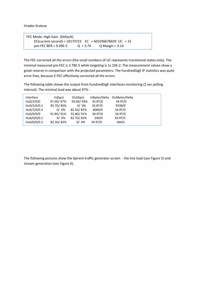
Hradec Kralove
The FEC corrected all the errors (the small numbers of UC represents transitional states only). The minimal measured pre-FEC is 3.78E-5 while targeting is 1x 10E-2. The measurement values show a great reserve in comparison with the projected parameters. The hundredGigE IP statistics was quite error-free, because E-FEC effectively corrected all the errors.
The following table shows the output from hundredGigE interfaces monitoring (2 sec polling interval). The minimal load was about 97% :
The following pictures show the Spirent traffic generator screen - the line load (see Figure 5) and stream generation (see Figure 6).
FEC Mode: High Gain (Default) EC(current second) = 10173723 EC = 601036678429 UC = 31 pre-FEC BER = 9.09E-5 Q = 3.74 Q Margin = 3.14
Interface In(bps) Out(bps) InBytes/Delta OutBytes/Delta Hu0/2/0/0 97.0G/ 97% 93.0G/ 93% 35.8T/0 34.9T/0 Hu0/2/0/0.2 85.7G/ 85% 0/ 0% 35.8T/0 9338/0 Hu0/2/0/0.3 0/ 0% 82.5G/ 82% 6060/0 34.9T/0 Hu0/0/0/0 91.8G/ 91% 91.8G/ 91% 34.9T/0 34.9T/0 Hu0/0/0/0.2 0/ 0% 82.7G/ 82% 240/0 34.9T/0 Hu0/0/0/0.3 82.3G/ 82% 0/ 0% 34.9T/0 184/0

Figure 5 The Spirent SPT-3U screen shot - line load
Figure 6 The Spirent SPT-3U - stream generation and latency
The average latency was about 6 985 µs (Praha_2-Hradec Kralove and back), so the average 100 Gbps line latency is approx. 3 492,5 µs.
The Figure 7 show the picture of the 100GE DWDM PLIM (there is visible DSP and optics there) and SPIRENT SPT-3U traffic generator/analyzer.

5. Field Tests in Live Network The production test in the live network covered real network traffic beeing transferred via 100GE DWDM link for a few days:
• The test CRS-3/4 was connected to the production P-router R130 in Hradec Kralove (see Figure 4)
• P-router R136 in Praha_2 was returned into the operation within the CESNET2 IP/MPLS backbone
• We changed the OSPF costs to reroute network traffic between the Praha_2 and Hradec Kralove
• We used both 159 km and 635,1 km DWDM paths
We experienced no errors on the DWDM optical level (G.709) and no errors on the IP layer as well. The CESNET2 network was stable.
6. Conclusion The conclusions from the CESNET2 network test are simple and clear:
DSP
Optics
Figure 7 100GE DWDM PLIM and SPIRENT SPT-3U 100GE traffic generator/analyzer

• CESNET2 optical network ONS15454 MSTP is ready for 100 Gbps technology (in parallel with the current 10 Gbps optical channels, which need DCUs)
• Pre-production 100GE DWDM PLIM works perfectly and its installation is plug and play • 4.2.1 IOS-XR EFT image on CRS-3 supports 100GE DWDM PLIM (no bugs found)
The planned parameters of production 100GE DWDM PLIMs will be better than those of the pre-production PLIMs (expected reach about 1500 km and others as well). We can start this year the planned migration to the 100GE IPoDWDM technology in the CESNET IP/MPLS network core. One of the most important considerations is the economical view as well, because the price for 40G OC768/STM-256 technology is comparable with the 100GE IPoDWM technology (according to the Cisco GPL).
7. Acknowledgement We would like to thank Cisco Systems for the opportunity to test the new 100GE IPoDWDM technology as the first in the world in the live production network and for the lending of the 100GE DWDM PLIMs and other equipment and components. Great thanks also to TR Instruments company for lending the 100GE traffic generator/analyzer Spirent SPT-3U.