100ge and 40ge pcs proposal - ieee 802 · 100ge and 40ge pcs proposal mark gustlin, gary nicholl,...
TRANSCRIPT

100GE and 40GE PCS Proposal
Mark Gustlin, Gary Nicholl, Oded Trainin
IEEE HSSG September 2007
2
Supporters• Pete Anslow - Nortel
• Med Belhadj – Cortina
• Brad Booth – AMCC
• Frank Chang - Vitesse
• Chris Cole – Finisar
• Craig Hornbuckle - SMI
• Arthur Marris - Cadence
• David Martin – Nortel
• Shinji Nishimura - Hitachi Ltd.
• Krishnamurthy Subramanian – Force10
• Hidehiro Toyoda - Hitachi Ltd.

3
Agenda
• Review of the 100G PCS/CTBI proposal
• Issues Update– How to support 40GE?
– How does variable skew impact the PCS
– How many virtual lanes do we need for 100GE and 40GE
– Should we support error rate monitoring
– What should the alignment block look like
– Finding VL alignment
– Overhead compensation
– Skew

4
Goals/Motivations• Specify a 100GE and 40GE PCS that can provide coding
for the electrical interface as well as the optical interface
• The PCS should allow for a simple optical module– No need for realignment in the optics (due to electrical or optical
skew)
– Optical module should not need to perform any coding or know about the coding
• Ensure that the PCS can scale with technology– Single PCS for current and many future PMDs
– Single PCS for current and future optical module interfaces
• Provide a PCS with low overhead– Line rate 100GE or 40GE regardless of packet size

5
Possible 100G Implementation Split
MAC
CGMII
MDI
RS
PCS
PMA
CTBI
PMD
Optical Module
MAC ASSP
• Electrical interface is high speed parallel serdes
• PCS is generic
• Relatively simple optical module (no PCS)
• PCS provides coding for electrical and optical
CGMII: 100G MII (logical interface?)
CTBI: 100G Ten Bit Interface?
• 40G Implementation split can be identical

6
Proposed 100GE/40GE PCS Overview
• 64B/66B based PCS (100G aggregate) • 10 Lane MAC/PCS to PMA/PMD Electrical Interface for 100GE
100G Ten Lane InterfaceEach lane runs at 10.3125G100G data is inverse multiplexed across the electrical lanes (66 bit blocks)
• 4 Lane MAC/PCS to PMA/PMD interface for 40GE• Support 1-10 PMD lanes all with the same electrical Interface and PCS• PMA maps n lane electrical interface to m lane PMD
PMA is simple bit level muxingDoes not know or care about PCS coding
• Alignment and most skew compensation is done in the Rx PCS only

7
Key Concept – Virtual Lanes• Data from the MAC is first encoded into a continuous stream of 64B/66B
blocks (100G or 40G aggregate stream).• The 100G aggregate stream is split into a number of ‘virtual lanes’, also
based on 64B/66B blocks • Each virtual lane is assigned a unique marker (as part of an alignment
block)• The number of virtual lanes generated is scaled to the Least Common
Multiple (LCM) of the n lane electrical interface and the m lane PMDThis allows all data (bits) from one virtual lane to be transmitted over the same electrical and optical lane combinationThis ensures that the data from a virtual lane is always received with the correct bit order at the Rx PCS
• The virtual lane marking allows the Rx PCS to perform skew compensation, realign all the virtual lanes, and reassemble a single 100G or 40G aggregate stream (with all the 64B/66B blocks in the correct order)

8
4 Lane PMD Example (20 VLs)
MDI
CGMII
X^58 Scrambling
Lane Striping (66b per virtual lane)
Add Alignment Blocks
PMA (10:4 bit gearbox)
PMD
CTBI
MDI
CGMII
X^58 Unscrambling
De-stripe (66b per virtual lane)
Alignment (66b and virtual lane)
PMA (4:10 bit gearbox)
PMD
CTBI
2:1 Virtual lane bit Muxing 1:2 Virtual lane bit Demux
PCS
Rate Adjust FIFORate Adjust FIFO
64B/66B Encoding 64B/66B Decoding

9
Tx PCS
Rx PCS
Tx PMDTx Gearbox PMA
Rx PMDRx Gearbox PMA
2:1
01020304050
02030
103050
41424344454
104
8
28384858
48123630
4030
6050
8070
414
2434
4454
818
2838
4858
014
18
18
Bit Flow Through
1: 2
42444
183858
Data moved due to electrical skew on the CTBI
Data moved due to the combination of electrical skew on the CTBI and optical skew, but virtual lane data always remains together (although on different CTBI lanes then it was originally sent)
Virtual Lanes are back with their bits in order, just transposed to different locations and skewed
100G 4 PMD Lanes Two Virtual Lanes per CTBI Lane, skew added

10
Issue Updates
• How to support 40GE?• How does variable skew impact the PCS?• How many virtual lanes do we need for 100GE and 40GE?• Should we support error rate monitoring?• What should the alignment block look like?

11
40GE “CTBI”
• Assume Optics/Interfaces can be: 4 lanes, 2 lanes or 1 lane• We would need 4 VLs to handle this case• Mux in optics is very simple when required• Everything else is the same as 100GE CTBI/PCS….• The figure below shows combinations of electrical and optical widths
that can be supported
MAC/PCS MAC/PCSPM
A
PMA
PMD
PMD
MAC/PCS MAC/PCS
PMA
PMA
PMD
PMD
MAC/PCS MAC/PCS
PMA
PMA
PMD
PMD

12
Variable Skew Handling• What happens if skew varies over time?
– Two main reasons it will• Relative or uncorrelated jitter/wander• Laser temp variation which changes the wavelengths and
hence the propagation time.
• First question is how much the skew can vary over time?• Pete Anslow’s presentation has the details, ranges from
psecs to nsecs depending on the technology chosen

13
Tx PCS
Rx PCS
Tx PMDTx Gearbox PMA
Rx PMDRx Gearbox PMA
2:1
01020304050
02030
103050
41424344454
104
8
28384858
48123630
4030
6050
8070
414
2434
4454
818
2838
4858
014
18
18
Bit Flow Through
1: 2
42444
183858
Variable skew due to laser temperature variation (also some relative wander)
Variable skew due to relative wander
Variable skew due to relative wander
14
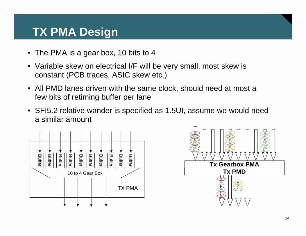
TX PMA Design• The PMA is a gear box, 10 bits to 4
• Variable skew on electrical I/F will be very small, most skew isconstant (PCB traces, ASIC skew etc.)
• All PMD lanes driven with the same clock, should need at most a few bits of retiming buffer per lane
• SFI5.2 relative wander is specified as 1.5UI, assume we would need a similar amount
Tx PMDTx Gearbox PMA
01020304050
41424344454
104
8
28384858
48123630
014
18
18
10 to 4 Gear Box
Buffer
Buffer
Buffer
Buffer
Buffer
Buffer
Buffer
Buffer
Buffer
Buffer
TX PMA
15
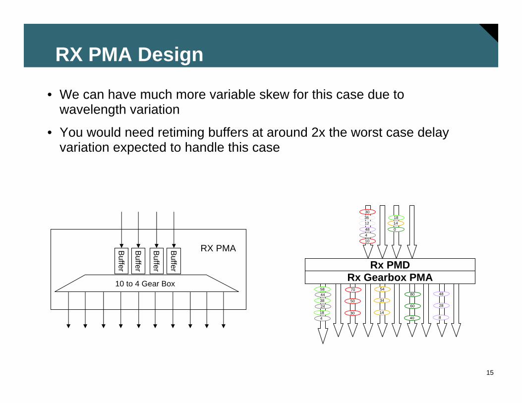
RX PMA Design
• We can have much more variable skew for this case due to wavelength variation
• You would need retiming buffers at around 2x the worst case delay variation expected to handle this case
Rx PMDRx Gearbox PMA
10448123630
4030
6050
8070
414
2434
4454
818
2838
4858
01418
10 to 4 Gear Box
Buffer
Buffer
Buffer
Buffer
RX PMA
16
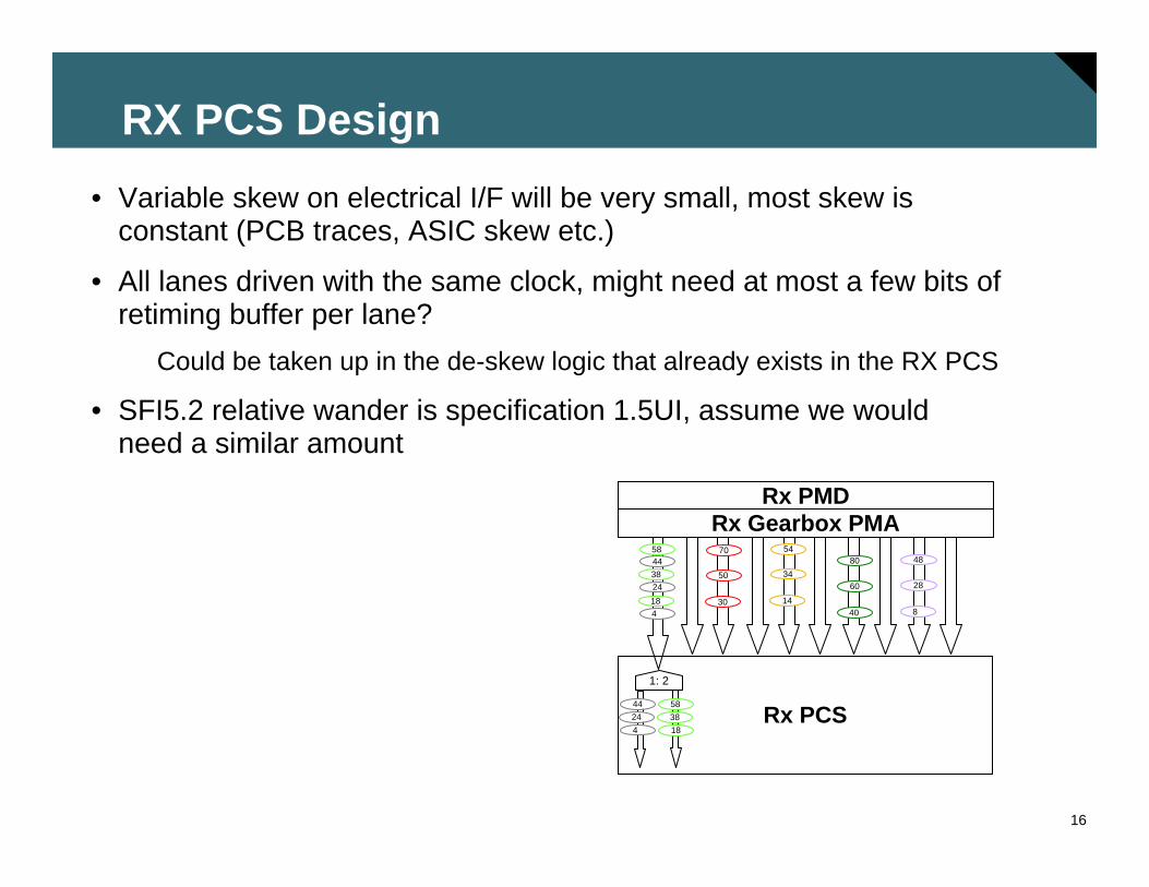
RX PCS Design• Variable skew on electrical I/F will be very small, most skew is
constant (PCB traces, ASIC skew etc.)
• All lanes driven with the same clock, might need at most a few bits of retiming buffer per lane?
Could be taken up in the de-skew logic that already exists in the RX PCS
• SFI5.2 relative wander is specification 1.5UI, assume we would need a similar amount
Rx PMDRx Gearbox PMA
4030
6050
8070
414
2434
4454
818
2838
4858
Rx PCS1: 2
42444
183858

17
Variable Skew Handling
• Find the maximum variable skew for all the PMDs…Actually we only care about the gearbox ones, so 10km and
40km only?
• This is not a concern for a 10 lane 100GE PMD (with a 10 lane electrical interface)?
If interface is clocked on a per lane basis?
• Also not a concern for a 4 lane 40GE variant?At least for a 4 lane electrical and 4 lane PMD

18
How Many Virtual Lanes for 100GE?
• For each PMD objective, what is the number of lanes being considered?
• Support at least 10km on SMF4 wavelengths
• Support at least 100 meters on OM3 MMF10 fibers
• Support at least 40-km on SMF4 wavelengths
• Support at least 10m over a copper cable assembly10 lanes

19
How Many Virtual Lanes are Needed for 100GE?
• It seems that the sweet spot is still 20 VLs…
• Supports currently envisioned PMDs
• Supports Electrical lane evolution such as a 4x25G interface
201, 2, 4, 5, 1010, 5, 4, 2, 110, 5, 2, 1
10, 5, 4, 2, 110, 5, 4, 2, 1
Number of Electrical Lanes
101, 2, 5, 10
601, 2, 3, 4, 5,101201, 2, 3, 4, 5, 6, 8, 10, 12
Virtual Lanes NeededSupportable PMDs
Sweet Spot?

20
How Many Virtual Lanes for 40GE?• For each PMD objective, what is the number of lanes
being considered?
• Support at least 100m on MMF4 fibers
• Support at least 10m over a copper cable assembly4 lanes
• Support at least 1m over a backplane4 lanes
4, 2, 1
Number of Electrical Lanes
41, 2, 4
Virtual Lanes Needed
Supportable PMDs

21
Lane Error Detection?
• Should we include a way to diagnose errors on a per virtual lane basis?
Mostly useful for lab debug etc?
• We could add a CRC or BIP block as part of the alignment word
• Would it allow us to isolate faults to a fiber, wavelength or electrical lane?
No in most cases
But over time you can sometimes tell…
• Use 8 or 16 bits for a CRC8 or CRC16, or BIP8 or BIP16Would be calculated over the data since the previous alignment word
BIP is sufficient for error isolation and simpler?

22
More on Error Detection
• If we Need better detection, check at each interface boundary?
That would allow us to have better error detection
Just check, no need to generate?
• Each Interface detects the frame and calculates the checksum

23
What should the Alignment Word look like?
• Requirements:Significant transitions and DC balanced – word is not scrambled
Keep in 66 bit form, but no relation to 10GBASER is needed
Contains Virtual Lane Identifier
BIP or CRC?
10 ~VL# VL#
Proposed Alignment Word
~BIP BIPFrm1 Frm2 TBDTBD

24
What is the right frame pattern?
• Requirements:Significant transitions and DC balanced – word is not scrambled
Keep the number of consecutive identical digits very low
When muxing these together the number multiplies (if no skew)
• OptionsRe-use SONET Frame pattern 0xF628 –
But has up to 4 consecutive digits?
Invent new one: 0x5566 – has up to 2 consecutive digits

25
Finding VL Alignment
• After reception in the rx PCS, you have x VLs, each skewed and transposed
• First you find 66bit alignment on each VL
Each VL is a stream of 66 bit blocks
Same mechanism as 10GBASE-R (64 valid 2 bit frame codes in a row)
• Then you hunt for alignment on each VL
• Alignment is declared on each VL after finding 4 consecutive non-errored frame patterns in the expected locations (16k words apart)
• Out of alignment is declared on a VL after finding 4 consecutive errored frame patterns
• Once the alignment pattern is found on all VLs, then the VLs can be aligned

26
Accounting for the Alignment Overhead
• Proposal is to send alignment words periodically on each VL
• If we send an alignment word every 16k 66 bit words, that is once each ~200usec
• On average you need to delete 2.5B of IPG per packet for Jumbo packets to accommodate clock differences and alignment overhead
Interface bit rate 1E+11Frame size (bytes) 9600Idles per ethernet frame (bytes) 12Packets per second 1299241Idle bits per second 124727159Clock mismatch (ppm) 200Alignment mismatch (ppm) 61Total ppm mismatch 261Total bits per second mismatch 26103516Ratio (Idles/Mismatch) 4.8
For 100GE Idle compensation
• An alternative is to increase the clock rate to account for the alignment overhead
• If we send an alignment block once every 1375 blocks, the lane clock rate is 10.32GHz

27
Skew Numbers
• Note that 1usec at 100Gbps = 100kbits of memory
• Numbers depend on what technology is ultimately used!
4 lanes< 1nsec?40km SMF
4 lanes < 20nsec?10km SMF
10 lanes~30nsec?100m OM3
NotesMaximum SkewPMD Type
• What is the maximum skew for the various interfaces?
• This drives the size of the de-skew memory in the Rx PCS

28
Re-name CTBI• CTBI and XLFBI - don't really like the XLFBI, but it is 40G
Four Bit Interface (C=100, XL = 40)
• Better name: SEI-x.y
• Scalable Ethernet Interface – BW class . VersionSEI-1.1 (4x10G)
SEI-1.2 (1x40G)
SEI-2.1 (10x10G)
SEI-2.2 (4x25G)

29
Issues/Next Steps
• Investigate error conditionsScrambler error multiplication
Alignment errors etc.
• Estimate the complexity of the PCS
• Fully define allowable skew
• Explore if the same PCS can be used for backplane and copper interfaces

30
Summary
• The proposed 100GE and 40GE PCS allows support for most PMD configurations
• Complexity is reasonable within the PCS
• Complexity in the optical module is low
• Based on proven 64B/66B framing and scrambling
• Electrical interface is feasible at 10x10G or 4x10G
• Allows for a MAC rate of 100.000G or 40.000G
• PCS and alignment overhead very low and independent of packet size
• Supports evolution of optics and electrical interfaces