cesium chloride compatibility testing program …6 ic 0 1 ,ballelie pji ir w :01. .-.t l .1bo.r ý*r...
TRANSCRIPT
I'
0E:8 i Q.906119
V SI ~M ii! ~< DcrMPAIIIIIA IiiY T 1.Sl INClt; F''I(:i<M-t A,%l,,. REVO"RT F IiSC;AL YEAR 1 9822
Pacific Notithwesr Laboratory R-ichIland, WA
DEC 82
ILL hlpsWui of Cal- IIC 1
N 'NSede glail wi
U-LIo
I I

6
1 ic 0 ,Ballelie Pji Ir w :01. .-. t L .1bo.r ý*r eft'
376-3177
February 9, 1983
Recipients of PUL-4556
Dear Recipients:
Re: Cesium Chloride Compatibility Testing Program Annual Repcrt - Fiscal Year 1984
Figures I and 2 (pages 9 and 12) were reversed in the printing of the document. Please replace the incorrect pages (9-121 with the enclosed pages.
Sincerely,
H. T. Fullam Staff Engineer Huclear Fuel Cycle Chemistry Section
4lW:lm
Sf

--o- WALL tHICKNESS MEASURED AT DIAMETRICALLY OPPOSED LOCATIONS"
01o INNER CAPSULE SERIAL NUMBER ETCHED ON CAOSIJLE
LOCATION NUMBER AND LOCATION LINE ETCHED ON CAPSULE
A MEASUREMENT AREA TYPICALLY 142" DIA.
CAPSULE WALL THICKNESS DETERMINED AT THE 18 LOCATIONS SHOWN USING AN ULTRASONIC TECHNIQUE. THE THICKNESS WAS DETERMINED AT AN AREA 34S" REMOVED FROM THE LOCATION NUMBER • AT THE END OF THE ETCHED LINE.
Locations Where the Wall Thickness of the Inner WESF Capsules Was Measured
9
FIGURE 1.
A
. I

I (
TABLE 1. Wal l Thicklness Data for Three of the - 316L Stainless Steel Inner Capsules ,Used in.Fabricating the Test !apsules
Inner Wall Wall Capsule Locati•n Thickness Locatioa Thickness
Njo. lo.a) (Inches) No.~ (Inches)
14073-A 1 0.1342 10 0.1401
2 0.1332 11 0.1387
.3 0.1341 12 0.1393
4 O.1j26 13 0.1392
5 0.1345 14 0.1382
6 0.1•41 is 0.1387
7 0.1345 16 0.1383
8 0.1341 17 0.1364
9 0.1341 18 0.1365
19073-C 1 0.1346 . 10 0.1431
2 0.1320 11 0.1425
3 0.1330 12 0.1417
4 0.1342 13 0.1431
5 0.1315 * 14 0.1414
60.1310 15 0.1419
7 0.1315 16 0.1399
8 0.1319. 17 0.1411
9 0.1307 18 0.1422
19073-G 1 0.1455 10 0.1317
2 I 0.144L 11 0.1306
3 0.1458 12 0.1318
4 0.1455 13 0.1326
5 0.1444 14 0.1306
6 0.1456 15 0.1303
7 0.1435 16 0.1315
8' 0.1454 17 0.1321
"9 0.1445 18 0.1302
(a) See Figure I for the meaning of the location numbers.
10
I
•.

.1
, -uter Capsul No0.
C- 1266
C-1272
C-1351
C-1365
C-1451
C- 1446
TAI9LF ?. Pertinent 7-ti on tho'.Jix [i . .
.. ;[sulIe, 'Ised i n the Thiermal.Aglng Te s
SI'nner 'adpsjle Cs) I :s No. kg uri es 'idtts (t)
19073-G ?,. 388 45,870 220
19073-B .2.701 56.930 273
19073-E 2.597 52,520 252
19073-D 2.472 44,740 2,14
1907.3-C 2.756 54,380 261
19073-H 2.716 51,140 245
(a) As of 4-5-82.
in the normal manner. The two capsules were then shipped to ORNL for section
ing and metallographic examination. The procedure ised in sectioning the
capsules is described in Section 4.5.
4.4 CAPSULE AGING
The six WESF CsC1 capsules to be thermally aged were placed in insulated
containers and allowed to self-heat to a maximum metal/CsCl interface temper
ature of 450 0C. Figure 2 shows a sketch of a test capsule in its insulated
container. Figure 3 shows a photograph of the insulated containers, contain
ing the CsCl capsules, in a holding rack in the hot cell.
The insulated container consists of a metal canister lined with block
insulation on the bottom and pipe insulation on the sides. Loose blanket
insulation is placed on top of the capsule in the canister. A stainless steel
thermowell, running the length of the WESF capsule, is fastened to each cap
sule using stainless steel hose clamps. The photograph in Figure 3 shows one
of the WESF capsules with the thermowell attached.
Six calibrated movable chromel-alumel thermocouples, each having a dif
feretit immersion depth, are used to measure the surface temperature of each
WESF capsule. Figure 4 shows the locations at which the capsule surface
temperature is measured. By rotating the six thermocouples between the ther
mowells on the six capsules, temperature profiles of each capsule are
11

MOVABLE THERMOCOUPLE 0i OF 6 EACH WITH A DIFFERENT IMMERSION DEPTH)
3C4L STAINLESS STEEL THERMO WELL .CLAMPED TO WESF CAPSULE
LOOSE FIBREFRAX BLANKET INSULATION
304L STAINLESS STEEL HOSE CLAMP (1 OF 31
WEST CESIUM CHLORIDE CAPSULE
3" CALCIUM SILICATE PIPE INSULATION 11""OR 1-1/2" THICKI
304L STAINLESS STEEL CANISTER
CALCIUM SILICATE BLOCK INSULATION 13° THICKI
FIGURE 2. Sketch of a WESF Capsule in Its Insulated Container
12
/.
I
I

Cesium Chloride Compatibility Testing Program Annual Report - Fiscal Year 1982
IL T. Fulfam
December IM6
Prepared for Mhe U.S. Department of Enery. under Contract DE-AC0•YRkLO 1830
Pa•if NorWest Labnaite *Operated low Owe U.S. Deg~rtment ow Emeip *by Sattefle Memora Insttute
a, 2
OBallelle
.
•4 . , • /,• " , , ''. * :
/
II
I .

C '0
�t4 r¶P. - '� ,,
* g.&'tr�� � � - '�. t.�-. � ,&&-"�Jfl 4 � z: �
4
4 4.. � �ts�t. � s,.
V.��?�*VWt � �'rZ --- '4
-- .,... -� Vj tI�'¼ -
- - t�rit0&-\&V�
'��t-'-� .
- nit- s-�- -' . . -t . . - �v&&�t.r:...-#T � �.?p -iT-
.4 V
ID�
tea xZ -tu'r
V
� 2<' __
A
� Z'L .4
p. '%- '� ., 4 4A4 t� 4 AJ � � C)
'.-I-'--. p - r--�-�.� g� �
'--&-41 � g 'A' rMfr� -� 4�5.$��5.AA4�tŽ.9..t :9ttv v;)sl �- �...
� 5. 5.
3
C, '
*
(J
- -5
'5-- -
I N

I-I
I ,
CESIUM CHLORIDE COMPATIBILITY TESTINIG PROGPAM ANNIUAL REPORT-- FISCAL YEAR 1982
H.T. Fullam
December 1982
Prepared for the U.S. Department of Energy under Contract DE-ACO6-76RLO 1830
Pacific Northwest Laboratory Richland, Washington, 99352
I
PL -4 ' 71
I I

A program was started in FY 1982 to evaluate the c ompatibill.ty of WE•i
produced CsCl with 316 L'stainless steel under the t6ermal conditions that
would be encountered in a geologic reposityry. The program is funded through
the Long-Term High-Level Defense Waste Program of the Department of Energy.
The major part of the program involves compatibility testing of six standard
WESF CsCI capsules at a maximum CsCl/metal interface temperature of 450°C.
The capsules are allowed to self-heat to the test temperature in insulated
containers and then held at-temperature for 2,200 to 32,000 hours. After
thermal aging, the capsules are destructively examined to determine the extent
of the metal attack by the CsCl. This repo~t describes the testing procedure
and summarizes the activities coiuoleted during the first year of the
program.
i i

C",tTENTS
ABSTRAC T.
1.0 INRODUCT,,N. .
2.0 OBJETIVES. .
3.0 TFST'.NG CRITERIA .
4.0 RADIOACTIVE COMPATIBILITY TESTS.
4.1 TESTING PROCEDURE
4.2 CAPSULE FABRICATION
4.3 ZERO-TIME CAPSULES'
4.4 CAPSULE AGING.
4.5 CAPSULE SECTIONING AND EXAMINATION.
4.6 METAL CONTROL SPECIMENS
4.7 HEAT TRANSFER STUDIES
4.8 PRELIMINARY TEST RESULTS
4.8.1 Zero-Time Capsules.
4.8.2 Thermal Aging Tests
5.0 CHEMICAL ANALYSIS 1F WESF-PRODUCED CESII
6.0 THERMODYNAMIC ANALYSIS OF THE 316L STAII WESF CESIUM CHLORIDE SYSTEML
7.0 PHYSICAL PROPERTY MEASUREMENTS.
M .O REFERENCES. . . .
Preceding page blank
* . iii
I
• 3
5
* . 7
• "7
UM CH
*... . . 11
15
17
17
* . . . 23
L. . .* . 23
•LORIDE 2 7
NLESS STEEL-29
. 37
43
I

1 Locations where the Wall Thickness of the I,.ner WESF Capsule was Measured
2 Sketch of a WLSF ICapsule'in its Insulated Container
3 Insulated Containers in a Holding Rack in the Hot Cel .. . .C. .
4 Locati-Ons where the Capsule Surface Temperature are Measured . , .
S Sectioning of'the Zero-Time Inner Capsules
6 Top View of the Electrically Heated Dummy Capsule and Insulated Container .
7 Side View of the Dummy Capsule and Insulated Container .
8 Typical Capsule Temperature Profiles Obtained Using the Dummy Capsule' ..
9 Average Temperature Profiles for the. WESF Capsule Held at-Temperature for 2208 Hours
10 Temperature Fluctuations Observed with t'apsule No. 1486 as a Function of Time .
11 Standard Free Energy of Formation of Various Chlorides as a Function of Temperature . .
12 The Effect of KCI Content on the Phase Transition Temperature of Cesium Chloride-Determined by Thermal Expansion Measurements . . ..
13 Thermal Expanslon Scans for KCl-CsCl Mixtures
TABLES
1 Wall Thickness Data for Three of the 316L Stainless Steel Inner Capsules used in Fabricating the Test Capsules . . . . . . . . .
2 Pertinent Data on the Six WESF CsC1 Capsules Used in' the Thermal Aging Tests . . . . . .
3 Maximum Test Temperatures for the Six WESF Cesium Chloride Capsules. . . . . .
vi.
I;
9
* . 12
* ' . 13
* . 14
* . 15
* . 19
* . 20
2. 2
* . 25
. . 26
* . 34
* . 38
* .39
10
11
*27
I I
t

; AfLES (Continued)
4 Estimates of imp~urit' Levels in WESF CsCl as-Determined by ICP ,N. .
5 Components of the 316L Stainless SteeliWESF Cesium Chloride System. .. .. . . . 31
6 Standard Free Energy of Formation Values for Selected
Chlorides at Various Temperatures .. .. . 33,
7 C6mposition of the Simulated WESF Cesium Chloride Mixture Used in the Physical Property. Measurements .... 40
8 The Effect of Impurities on the Phase Transition Temperature and Melting Point of CsCl. . . ... 40
•vii

2
1.0 !NTROD4JCTION
At Hanford, fission product cesium, cortaining 20-4W! cesium-1.37, is
recovered from the high-level waste, and coiverted to cesium chloride. The
cesium chloride is doubly encapsulated in small hi)h-intajrity 316L stairnless steel capsules. The cesium chloride capsules are then stored ir. water basins on the Hanford Reservation.
The cesium chloride is loaded into the inner :1161 st"iniess steel
capsules by melt casting. Each capsule, which has 'an I.D. of two *nches andan inner length of about 19 inches, contains up to three kilograrms of cesium'
chloride. The capsules contain up to about 70,000 Ct of cesium-137, depending
on the age and purity of the 'ission product cesium chloride.
Recovery of the cesiuw, from the high-level waste and its subsequent
purification take place in B-Plant. Conversion of the purified cesium to
cesium chloride, encapsulation of the c'esium"chlorile, and storage of the
cesium chloride capsules take place in the Waste En:apsulation and Storage Facility (WESF). Both facilities are currently operated for the Department of
Energy (DOE) by the Rockwell Hanford Operation (RHO).
The Department of Energy is currently considering the geologic disposal
of the cesium chloride capsules produced &nd stored at WESF. In order to evaluate the hazards associated with the geologic disposal 'of the WESF cesium
chloride capsules, reliable estimates of long-term attack of the capsule
material by the cesium chloride under repository conditions are required.
Currently available data on the compatibility of WESF-produced cesium chloride with 316L' stainless steel are not adequate for making the required
estimates. The Cesium Chloride Compatibility Testing Program was started at
the Pacific Northwest Laboratory in Fiscal Year 1982 to obtain the needed
compatibility data. The program will take approximately five years to
complete. The work is funded by the Long-Term High-Level Defense Waste Pro
gram of the. DOE. This report summarizes the program activities for Fiscal
Year 1982.

I
2.0 OBJECTIVES
,The primary objective of the cesium chloride compatibility testing pro
gram is to evaluate the compatibility of WESF-produced cesium chloride with
the 316L stainless $teel capsul'e material under the conditions that would be
encountered in a geologic repository. Sufficient short-term compatibility
data are to be obtained with the WESF produced cesium chloride to permit
useful estimates of long-term attack of the 316L st ainless. steel by the CsCl
under repository conditions.
Secondary objectives of the program are to:
'determine the effects of impurities in the WESF-produced CsCl on the
attack of the stainless steel and identify the reaction mechanisms
involved, and
* determine the effects of the impurities in the WESV-produced CsCl1on
the melting point and solid-solid phase transition of CsCl.
3
II!f/ v'

3.0 TESTING CRITERIA
A number of variables can affect -the aompatibility of the WESF-produced
CsCl with 316L stainless steel in a geologic repository. The more important
variables include:
0 the reaction temperature (316L stainless steel/CsCl interface temper
ature),
9 impirities in the WEST-produced CsCl,
* changes in the microstructure of the 316L stainless steel due to
thermal aging reactions (I.e.. precipitation of carbide phases,
etc.), and
degree of contact between the 316L stainless steel and the CsCl.
Program scope does not include a detailed testing program to evaluate all of
the variables which affect 316L stainless steel/WESF CsCl compatibility.
especially with regard to impurity effects. The limited testing program now
underway was designed on the following bases:
"* the 316L stainless steel/WES CsC1 interface temperatures in the
geologic repository will not exceed 4500C,
"* the WESF CsCl capsules will be pl'aced in the repository in a vertical
orientation, and
"* the radioactive compatibility tests Are to be carried out with stan
dard production WES CsCl capsules without regard to possible varia
tions in the composition of the CsCl between capsules.
The last limitation can have a significant effect on the overall validity of
the radioactive compatibility data obtained since theoretical considerAtions
indicate that certain impurities in the CsCl could have a significant effect
on the metal attack. The data obtained in the radioactive tests now underway
5
/

will provile a measure of the metal attack for a given set of '4E*;? capsul1es
but will not show how the attack may vary with changes,in the CsCl composi
.tion.
The cesium chloride compatibility testing program is divided into five
tasks:
1. radioactive compatibility data lasting up to 32.000 hours using
standard WESF CsCl capsules,
2. heat transfer studies to define the relationship between the surface
temperature of the inner and outer capsules of the WESF CsCl capsule,
3. chemical analysis of the CsCl from a batch of WESF produced CsCl (the
CsCl product from WESF is not analyzed, although t&e Cs feed solution
to WESF is analyzed),
4. a thermodynamic analysis of the WESF CsC1/316L stainless steel
system,
5. physical property measurements on CsCl-impurity mixtures.
The major emphasis throughout the duration of the program is on the first
task.
6
I

I
4.0 RADIOACTIVE ,();PAT.,'QLTY TE.,
The.radioactive compatibility tests are designed to provide the short.term data needed to estimate long-term attack of 316L stainlEss iteel by WESFproduced CsC1 at a maximum metal!CsCl interface temperature'of 450'C. The data obtained from the tests should meet this rtequirement, within the limitations described in the previous section.
4.1 TESTING PROCEDURE
In the radioactive compatibility tests six standard WESF cesium chloride capsules are placed vertically in individual Insulated container, and allowed to self-heat to a maximum metal/CsCt interface temperature of 4500 C. The capsules are maintained at temperature for times of 2000, 4000, F'0O0, 16,000, 24,000, or 32,000 hours. When thermal aging of 4 capsule is completed, it is removed from the Insulated container, cooled, and shipped to the Oak Rioge National Laboratory (ORNL) for sectioning and examination. At ORNL small samples are taken from the inner capsule at various locations and subjected to. metallographic examination to determine the extent of metal attack by the CsCl. Some of the samples will also be subjected to electron microprobe analysis in an attempt to identify the reaction mechanisms involved in the metal attack.
In addition to the aging tests, two WESF inner capsules were sectioned and examined immediately after filling with CsCl. This provides a measure of the metal attack that occurs during the loading operation when the CsCl is molten. These two "zero time" capsules will serve as the controls for determining the metal attack resulting from the thermal aging tests.
Because of their high cesium-137 content, all work.with the WESF CsCl ' capsules, including sectioning and examiration of test samples, is carried out in heavily shielded facilities (hot cells).
4.2 CAPSULE FABRICATION
The CsCl capsules used in the radicactive compatibility tests are typical WESF-production capsu'es prepared In the normal manner and meeting all RHO and DOE QC and QA requirements. All capsule components were fabricated in the usual manner with one exception. In order to accurately determine metal
7
I

I I
*attack by the 'W2 * it is necessdry tj'know the initial 1I t.' .j k .r..s of tne inner ca:sjjles dt the points were the samqplis are take'n for mnpta)!olrapnic
examination. Therefore, the wall thickness of each of the eijht inner '.dp
sule, used in the tests was measured at the P; locations shown in Figure 1
before the capsule, wa- filled with CsC1. An ultrasonic procedure was used to
determine the wall thickness.
Table I shows wall thickness data for threp' of the inner capsules, which
is typical of all eight capsules. The data show that the wall thickness is
fairly uniform,over thelength of a.capsule along any given surface element,
with thickness variations rarely exceeding 0.003 Inches. The data dlso show.
however, that the tubing used in fabricating thie inner capsules is not concen
tric,'and substantial differences in wall thickness (up to,0.015 inches) were
observed at diametrically opposite locations on the capsule. Because of these
variations, the initial wall thickness of the inner test capsule is only
,known, with any degree of certainty, at those locations where the wall thick
ness measurements were made. The measurement locations are clearly shown on
the test capsules by means of location numbers and-location lines etched on
the surface of the capsule (see Figure 0)
Loading of the molten cesium chloride into the inner capsules at WESF is a batch operation. Sufficient cesium chloride is melted in each batch to fill
seven capsules. Each of the test capsules, including the two zero-time can
sules, was loaded from a different batch ot cesium chloride. Therefore, the
chemical composition and cesium isotopic composition of the cesium chloride in the different test capsules can vary significantly. Table 2 gives the pertinent data on the six capsules used in the thermal aging test,. From the data,
one can calculate an approximate cesium-137 isotopic concentration for each
capsule, but the amount and types of impurities present in each capsule are
unknown.
4.3. ZERO-TIME CAPSULES
The two "zero-time" inner capsules we-e filled with CsC1 in the normal manner. After removal from the loading apparatus, the CsC1 was removed from
the two capsules by water leaching. Each empty capsule wes rinsed and thor
oughly dried and then sealed by welding the end cap in place. The sealed Inner capsules were decontaminated. leak-checked, and sealed in outer capsules
8
t

MOVABLE THERMOCOUPLE 11 OF 6 - EACH WITH A DIFFERENT IMMERSION DEPTH)
304L STAINLESS STEEL THERMOWELL CLAMPED
TO WESF CAPSULE
LOOSE FIBREFRAX BLANKET INSULATION
304L STAsNLESS STEEL HOSE CLAMP I1 OF 31
WEST CESIUM CHLORIDE CAPSULE
3"' CALCIUM SILICATE PIPE INSULATION
(11 OR 1-112" THICK)
304L STAINLESS STEEL CANISTER
CALCIUM SILICATE BLOCK INSULATION (3- THICK)
FIGURE 1. Locations Where the Wall Thickness of the Inner
"WESF Capsules Was Measured
9
Sp
. II
I

,-W I
P•LF I. alfI Thickness Uat j f-)r Thre.- of the I.bL Stain.less 'Atel inner '.apsuj'%
"Used in.Fabri-catinci the Test '"apsules
inner 'apsul e
1QO073-A
19073-C
19073-G
Locatior Oa)
2
3
4 5
6
7
8
9
2
3 4
5 6
7
8
2
3 4
5
6
7 8
9
Wall1 Thickness
(inches)
0.1342
0.1332
0.1341
0.1326
0.1345
0.1341
0.1345
0.1341
0.1341
0.1346
0.1320
0.1330
0.1342
0.1315
0.1010
0.1315
0.1319
0.1307
0.1455
0.1441
0.1458
0.1455
0.1444
0.1456
0.1435
0.1454
0. 1445
Locatioa N;o. (a)
10
12
13
14 15
16
17
18
10
11
12
13
14
15
16
17
18
10
II
12
13
14
15
16
17
18
Wal 1 Thick ness
r(inhes)
0.14U1
0.1387
0.1393
0.1392
0.1382
0.1387
0.1383
0.1364
0.1365
0.1431
0.1425
0.1417
0.1431
0.1414
0.1419
0.1399
0.1411
0.1422
0.1317
0.1306
0.1318
0.1326
0.1306
0.1303
0.1315
0.1321
0. 1302
(a) See Figure 1 for the meaning of the location numbers.
10
i

, I
TAU'LE .. Pertinent Jati on t'Ve C IE'ir;frl CdpsuIes Isse'd in the Therrmal i nq Tests t )
)uter Cdpsule Inner Capsule CsC Cs No. No. kg (Guries Watts (t)
C-1266 19073-G' 2.388 45,870 220 C-1272 19073-B 2.701 56,930 273 C-1351 19073-E ?.597 52,520 , 252 C-1365 19073-D 2.472 44,74.0 214 C-1451 19073-C 2.756 54,380 261 C-1486 19073-H 2.716 51,140 245
.(a) As of 4-5-82.
in the normal 'manner. The two capsules were then'shipped to ORNL for sectioning and metallographic examination. The procedure used in sectioning the capsules is described in Section 4.5.
4.4 CAPSULE AGING
The six WESF CsCl capsules to be thermally aged were placed in insulated containers and allowed to self-heat to a maximum metal/CsCl interface temperature of 450"C. Figure 2 shows a sketch of a test capsule in its Insulated container. Figure 3.shows a photograph of the fnsulated containers, containIng the CsCl capsules, in a holding rack in the hot cell.
The insulated container consists of a metal canister lined with block Insulation on the bottom and pipe Insulation on the sides. Loose blanket insulation is placed on top of the capsule in the canister. A stainless steel thermowell, running the length of the WESF capsule, is fastened to each capsule using stainless steel hose clamps. The photograph in Figure 3 shows one of the WESF capsules with the thermowell attached.
SiA calibrated movable chromel-alumel thermocouples, each having a different immersion depth, are used to measure the surface temperature of each WESF capsule. Figure 4 shows the locations at which the capsule surface temperature is measured. By rotating the six thermocouples between the thermowells on the six capsules, temperature profiles of each capsule are
11

NVAIL THICKNESS MEASURED AT DIAMETRICALLY OPPOSED LOCATIONS
510. INNER iCAPSULE SERIAL NUMBER
ETCHED ON CAPSULE
LOCATION NUMBER AND LOCATION LINE ETCHED
- '2 #11 )ON CAPSULE
2 #-- .•-- 12A
4- #13
!.5O" MEASUREMENT AREA
# J • 4TYPICALLY 142- CIA.
I 5 #1
"CAPSULE WALL THICKNESS DETERMINED
AT THE 13 LOCATIONS SHOWN USING
AN ULTRASONIC TECHNIQUE- THE
THICKNESS WAS DETERMINED AT AN AREA 4 > -#17 31" REMOVED FROM THE LOCATION NUMBER - AT THE END OF THE ETCHED
LINE.
17# 2.3Fu
FIGURE 2.. Sketch of a WESF Capsule in Its Insulated Container
12
I

'• lilt L
A
FIGURE 3".'The Insulated Containers in a Holding Rack ir the Hrot Cell
• I -I

a
i
0
4
m
4
I
OUTER CAPSULE BOTTOM
S-THEHMOWELL
---- TC#2
Iq.;.j
--- 7TC84
.------- TCOS
TC*S i/t"..
t
FIGURE 4. 'Locations Where the Capsule Surface Tempera+ures are Measured
14
1 11
ii I..
VI
'is..12.
UE:811
I I IW
I I
I
own"&

obtained on a-periloiic basis. AS will be shown later, substintial tem; ,ratAve
gradients exist between the middle and ends of eachcapsule. Tne t•mpe;'4tjr
readings are normnally taken on a weekly basis,
The temperature readings obtained provide a qteasure ofthe surface tea
perature of the outer capsule.' It was impossible to measvre directly the
inner capsule/CsCl, interface temperature. Therefore, the inner capsule!fsl
interface temperoture'must be calculated from the outer capsule surface ten
perature. In order, to determine the relati,onship between the outer capsule
surface temperature and the inner capsule/CsCl interface temperatute, exten-.
sive heat transfer studies were carried out with an electrically heated dummy
WESF capsule., These studies are discussed in Section 4.7. Data from the heat
transfer studies were also used todesign the insuleted containers to assure
the test capsules reached tVe required aging temperature.
4.5 CAPSULE-SECTIONING AND EXAMINATION
The test capsules are shipped to ORNL for sectioning and examination. In
the case of the thermally aged capsules, the capsules are shipped to ORNL
without removing the contained CsCl. At ORNL the outer capsules are opened.
and the inner capsules removed. The two zero-time inner capsules were sec
tioned as shown in Figure 5. Four ring sections were cut from each inner
capsule, as shown, and then a small sample was cut from each ring for subse
quent'examination. Edch sample contained an area where the capsule wall
thickness had been measured. The thickness of the sample was measured with a
micrometer. Each sample was mounted lengthwise, ground'to the midpoint,
polished, and photomicrographs of the reaction zone obtainedt After etching,
additional micrographs of the sample were obtained.
The thermally aged inner capsules will be sectioned in slightly different
locations than the zero-ti-te capsules. This is necessary because of the
temperature gradients that exist over the length of the test capsales during
,aging. The maximum "nterface temperature does not correspond to any of the
four locations where test samples were taken from the zero-time capsules.
Sectir-ing of the aged capsules will be adjusted'so that a sample is obtained
at the surface element passing through the measurement areas and the point of
maximum temperature. Since the Initial wall thickness along a surface element
.of a capsule does not vary by more than 0.001-0.003 inches, the initial wall
15

I'
CAPSULE TOP
#2
93--4-- -4
31;4"
14
T
I4. RING #4
4'.
--- i- RING #3
-RING #2
-- I- RING #1
4.3"
5.
4
FOUR RING SECTIONS CUT FROM THE INNER CAPSULE AT THE
LOCATIONS SHOWN - EACH' RING ABOUT 314" WIDE ,
AREA WHERE WALL THICKNESS WAS MEASURED
SAMPLE ABOUT 12" WIDE CUT FROM EACH RING SECTION - AT
THE END OF THE ETCHED LINE SO THAT THE SAMPLE INCLUDES THE AREA WHERE THE WALL THICKNESS WAS MEASURED
FIGURE 5. Sectioning of the Zero-Time Inner Capsules
'4
#6
#7 -
I i
I

& *
thickness at the point where the sample is taken will be known with sUffiCiEnt'
accuracy.
4.6 METAL CONTROL SPECIMENS
When 316L stainless steel is held in contact with. WEiF-produced CsCl at
temperatures up to 450*C for extended periods of time, it is possible that
chemical attack by the CsCl could produce changes in the microstructure of the,
metal. The thermal aging of the 316L stainless steel may also produce changes
in its microstructure. To help differentiate between microstructural changes
produced by thermal aging and those resulting from chenical attack, control
samples of 316L stainless steel are being aged in argon at 4000, 4500, and
500C for varying times up to 32,000 hr. The aged samples are subjectsd to
metallographic examination. The photomicrographs obtained will show what
microstructural changes result from the thermal aging.
The control samples were cut from a rejected WESF stainless steel inner
capsule. Each sample was sealed in an argon-filled quartz envelope. The
samples are heated in muffle furnaces whose temperatures are maintained within
W2C of the control temperatures using solid state proportioning
controllers. The samples are maintained at temperature for 2000, 4000, 8000,
16,000, 24,000, or 32,000 hours (the same times as the radioactive test cap
sules).
4.7 HEAT TRANSFER STUDIES
A large number of heat transfer studies were carried out using an elec
trically heated dumny WESF CsCl capsule. The objectives of the studies were
,to:
"* determine the relationship between the outer capsule surface tempera
ture and the inner capsule surface temperature (the inner capsule
surface temperature and the inner capsule/CsCl interface temperature
were assumed to be the same), and
"* obtain the heat transfer data needed to design the insulated con
tainers used in the radioactive compatibility tests.
17

The electrically heated duriy capsule was fab.'icdted froin standard 313L stuinless steel WESF inne~r and outer capsules. The dummy capsule was moeunted vertically in an insulated €ontdi1Lr for the heat transfer tests'. A 0.5 in. dia. 500 watt cartridge heater was used.to heat the capsule., The heater qas inserted in theinner capsule through holes drilled in the tops of the inner and outer capsules. Power to the heater'was cdntrolled with a variab'le trapsFormer. Heater voltage was measured witha digital voltmeter and the heater current with an AC ammeter. A narrow slot was machined the length of the cuter surface of the inner capsule to serve as a thermowell. The slot was covered with a thin strip of 316L stai'nless steel sheet welded to the capsule
surface. A movable thermocouple inserted in the slot served to measure the capsule temperature at various locations along its length. Small holes,iri the endcaps of the inner and outer capsules provided free movement of the thermo
couple.
Four thermowells, fabricated from stainless steel tubing,. were welded lengthwise to the outer capsule surface 90o apart. A fifth stainless steel thermowell was fastened to the outer capsule using three stainless steel hose' clamps. Five movable thermocouples placed in the thirmowells were used to measure the outer capsule surface temperature at various locations along the capsule length. A loose thermocouple was also placed in the space between the -outer capsule and the pipe insulation around the capsule. Outputs of the seven thermocouples were monitored with a multipoint digital thermometer.
All of the thermometers and the measuring instruments were calibrated
prior to use.
The dummy capsule was mounted vertically in the insulated container.- The
container was lined with three inches of block insulation on the bottom and pipe insulation on the side. The capsule was covered with loose blanket insulation. Thg thickness of the pipe insulation could be varied from one to
three inches. Figures 6 and 7 show top and side views of the dummy capsule and insulated container.
In carrying out a test, a constant voltage was applied to the heater and the system was all-owed to come to thermal equilibrium. When equilibrium was reached, the inner and outer capsule surface temperatures were measured. By moving the thermocoupler up and down the length of the capsules, temperature profiles of the inner and outer capsules were obtained as a function of power
18
I
I .

( ( a.
CARTRIDGE HEATER "AE A THERMOWELL CLAMPED
TO OUTER CAPSULE
OUTER CAPSULE
LOOSE THERMOCOUPLE PLACED - _BETWEEN INSULATION AND
- CAPSULE
* -. -GROOVE MACHINED THE LENGTH OF THE INNER CAPSULE GROOVE COVERED WITH 20 GA. 3041 SS SHEET
- GROOVE SERVES AS THERMOWELL
THERMOWELL WELDED TO OUTER
" CAPSULE 01 OF 41 304L SS HOSE CLAMP
-.--.---- 1 dOF 31
3" CALCIUM SILICATE PIPE INSULATION - I*'- 304L SS CANISTER
TO 3" THICK
FIGURE 6. Top View of the Electrically Heated Dumny Capsule and lnsuldted -otiiher
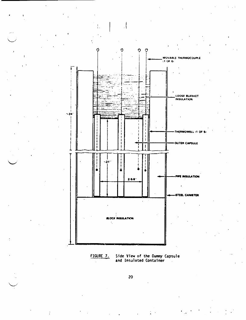
,I I MOVABLE TH&RMOCOUPLE ii OF 61
I F"
.. LOOSE BLANKET
HERMOWELL 11 0
-OUTER CAPSULE
2-518"
- Li - b - I - ImEm Iul.L
KoCK I4SULATION
-P iN WSULATION
-.u---STEEL CANISTER
F Si
I I
FIGURE 7. Side View of the Dummy Capsule and Insulated Container
20
4

input to the he3i)er dTd in',Ilation t' 1i.Jkness. Figure d shows the results
obtained at a power input'of 141 watts using 1.5 inches of pipe ins-uldtion.
im.ilarly shaped curves wer4 obtained with other power inputs and thicknesses
of insulation. The results show that a'significant temperature Iradient
exists between the middle and ends of the capsules. The maximun temperatire
of Iboth the inneý and outer capsules: occurs nine inches up from the bottom of
the- outer cbpsule regardless of the power input to the heater and the thick
ness of the pipe insulation around the capsule. At each elevation, tOe fbur
thermocouples in the welded thermowells agreed with each other within 5VC.
This was true even if the inner capsule was touching the outer capsule along
one side. At a given elevation, the thermocouple in the thermwnell clamped to
one outer capsule read 70 to 14°C lower than the average of the four thermo
couples in the welded thermowells, depending on the power input and insulation
thickness. The loose thermocouple positioned between the capsule and, the
insulation gave the same reading, within ,l1C,' as the ttermocouple in the
clamped thernowell at the same elevation.
Referring to Figure 8, it can be seen that the AT between the inner and
outer capsules varied with the elevation. The AT also varied with the power
input to the heater and the thickness of the pipe insulation. It is interes
ting to note that even at the bottom of the capsule where the inner and outer
capsules were in direct contact, there was still a AT of 100-20"C between the
two capsules.
Sufficient heat transfer tests were run to determine the AT between the
'inner and outer. capsules as a function of elevation, power input, and insula
tion thickness. From these data, the insulated containers were designed to
give the desired maximum 316L stainless steel/WESF CsCl interface temperature
of 4500C. T1he design was complicated by two factors:
0 the decay-energy of the six WESF capsules varied from 214 to 273 watts (as of 4-5-82), thus requiring different thicknesses of insula
tion around the capsules, and
* there is marked disagreement between various sources on how much of
the cesium-137/barium-137m decay energy is absorbed within the WESF
capsule.
21
I

I , I
\
, \ \
18
U A INNER CAPSULE 0 OUTER CAPSULE - WELDED THERMOWELL
AVERAGE Or FOUR VALUES) 0 OUTER CAPSULE - CLAMPLtEp THERMOWELL
O 0 OUTER CAPSULE - LOOSE THERMOCOUPLE
SPOWER INPUT TO INNER CAPSULE * 141 W ATTS
1.5 INCHES OF PIPE INSULATION 2 AROUND OUTER CAPSULE
I
3 11 .200 250 300 350 400 41
TEMPERATURE. *C
FIGURE 8. Typical .Capsule Temperature Profiles Obtained Using the Dummy Capsule
22
*
in designing the insu1,cter contdiners, it waa, assmJ,5d that 55-60- 9f the le,.ay energy is absorbed in the capsule. Suhse.qu.ýnt results with the s.i c'apsules indicated that 57 to 62'!, of the energy was absorbed in the capsule. As will be shown in Section 4.8.2, the dc%'ign of the six insulated containers was sufficient to maintain the average rIaAimum metal/CsCl interface temperature of each capsule between 450° ard d 460'C.
4.8 PRELIMINARY TEST RESULTS
4.8.1 Zero-Time Capsules
The two zerq-time capsules were shipped to ORNL In April for sectionlng and examination. The capsules were sectioned as described in Section 4.5. Metallographic examination of the eight samples taken from the two capsules has been completed by ORNL. Prints-of the photomicrographs obtained were not received at PNL, however, in time for inclusion In this report. Preliminary observations of ORNL staff indicated that none of the test sa:ples exhibited significant attack. Detailed evaluation of the micrographs will be needed, however, to confirm this conclusion.
4.8.2 Thermal Ag9ing Tests
Thermal aging of the si WESF capsules was started in April 1982. Aging of the 2000 hr capsule was c mpleted in July 1982 (the capsule was actually maifr.3ined at temperature for 2208 hours). Shipment of the capsule to ORNL for sectioning was delayed until September because of problems with thf incell transfer crane and unavailability of the NRBK-43 shipping cask. Ourivig the time between the end of the test and shipment to ORNL, the capsule was held in the hot cell; the maximum 316L stainle%% steel/CsC1 Intejr:fie t.emperature ouring the period averaged 130C.. Holding the capsule at a maximum temperature of 1300C for about two months is not expected to have a significant effect on the attack of the metal by the CsCl.
Sectioning and examination of the 2000 hr test capsule was scheduled to be completed by'the end of FY 1982. The delays In shipping the. capsule to ORNL prevented hiis milestone from being met. Examination of the capsule should be c.mpVieted by the end of November 1982.
23
I

F i -ure 1 Shows the toip!:rrjtjr.- pr.afi Ies' f i the *ýiI ile ,'j]I f-)r 2V',T
hours. The temperature profiles are similar tj those obt-i0ned wit'i the elec
trically heated dummry cdpsules an~d are typical of the six ý[Eý" tes•t
capsules. The tpmperature profiles shown in Figure 9 represent the average
surface temperatures fur the test period (2208 nours). Considerdble fluctua
tions in surface temperature were observed and continue, to be .erved betweepi
measurements. Figure 10 shows the inner capsu,le surface temperat'j.e for
capsule No. 1486 which' has been under test for 3192 hours. The temperature
f.luctuations observed with capsule No. 1486 represeft the worst case situa
tion. The other capsules exhibit similar temperature fluctuations, but they
are less severe than those shown in Figure 10.
It is difficult to explain the rather large temperature fluctuations
observed.. Since the heat output of each capsule is essentially constant over
the time spans under consideration, the variations cannot be explained by
changes in the energy absorbed within a capsule. Fluctuations in cell air
temperature and air flow could account for some of the variations, but it is
unlikely they could account for the magnitude of the fluctuations observed.
Tests with the electrically heated dummy capsule showed that the thermocouples
used to measure the surface temperature reached a constant temperature within
ten minutes after being inserted in the thermowell. Since the test thermo
couples are placed in the thermowells at least 20 to 30 mi.nutes before the
readings are taken, they should have reached a constant temperature when the
readings were taken. Overall, it appears likely that the the temperature
fluctuations-observed are the result of several, unrelated factors.
,The test criteria call for the capsules to be held at a maximum
metai/CsCl interface temperature of 450*C. Because of the differences in the
decay energies of the six capsules. itlwas impossible to bring all six cap-*
sules to exactly 450C. As shown in Table 3, however, the average maximum
temperatures of the six capsules are being maintained between 451°C and
458*C; which is adequate control for the tests.
24
II

I 1 1
OUTER CAPSULE TOP
250 300 300
AVERAGE CAPSULE SURFACE TEMPERATURE. 'C
FIGURE 9. Average Temperature Profiles for the WESF Capsule Held at Temperature for 2208 Hours
25
20 7
20
18
14
121
U, w I U K w -I U,
U
w I
0 'U I
0 I0 S 'U I Iz 0
4 IV.
200500

.(
TCA4 430 S-C0
CL
TCirb
U
410
TC m2
U
o~I T C 86
370 ••T,
Ice
CAPSULE NO, 1480 24S WATTS SEE FIGURE 4 FOR LOCATIONS WHERE TC'S MEASURE THE SURFACE- TEMPERATURE
0 400 800 1,200 1.600 2,0O00 2.400 2,800 3.200 EXPOSURE TIME, tmurs
F.IGURE 10. Tempereture Fluctuations Observed With Capsule No. 1486 as a l uml tion ot limo.,
.1l

I ABLFE 3. Maximnum lest ,lenperatires for the .. .Six WESF Cesium Chloride Capsules
Average llaxi p Exposure Number of Temperaturelal
Ca.psule No. IHours Readi ngs
1266 2208 14 I 455t4
1272. 3360 18. 456t6
1351 3192 18 453t4
1365 3192 18 45145
14.51 3192 '18 , 458t4.
1486 3192 18 453t8
(a) Average maximum inner capsule surface temperature for the exposure time
shown.
5.0 CHEMICAL ANALYSIS OF WESF-PRODUCED CESIUM CHLORIDE
The cesium chloride produced at WESF is not analyzed for impurities. The
cesium feed solution to WESF is analyzed periodically, but it is impossible to
tell from the feed solution data what is the impurity content of each batch of
CsCl. The WESF specification for the feed solution requires that the molar
ratio of Na + K + Rb to Cs be 0.15. If one assumes that the Na, K, and Rb
are present in equimolar concentrations in the feed solution, the maximum
permissible concentrations. of NaCi, KCI, and RbCl in the CsC1 would be about
1.6 wt%, 2.0 wt%, and 3.3 wt%, respectively. If potassium were the only
impurity in the feed solution, its concentration in the CsCl would be <6.2
wt%. The problem is further complicated by the corrosion of process equipment
in WESF whick can add impurities to the*CsCl. Certain impurities, such as
chlorides of iron and chromium, are expected to have a detrimental effect on
the compatiblity of the WESF CsCl with the 316 L stainless steel capsule, even
when present In low concentrattons.
Because of the high radiation levels associated with the 1 3 7 Cs, large
dilutions are required prior to analysis of WESF CsCl solutions using the
lightly shielded analytical equipment currently available at Hanford. This
prevents the accurate determination of low level impurities in the WESF CsCl.
27

1. __ _ !
As part of the current proqrdrl, a l imi,ted study was jndertaken to seie if the cesium pould he adequately separated from the impurities to permit reliable anaiy'sis: of the impurities using, available analytical procedures. Several ion exchange dnd solvent exttaction procedures were eval'uated, but none, provided.the required separation.
In order to obtain sc.-ne measure of the impurity content of, the WES CSCI, it was decided to use the dilution approach and have RHO analyzethe diluted CsCl solution using the ICP. A single sample of CsCl was taken from one of the batches of CsC1 used to fill the zero-time capsules.. A weighed amount of the sample was dissolved in reagent grade nitric acid. A small aliquot of the solution was diluted with ultrahigh purity nitric acid, and samples of the diluted solution analyzed by ICP. A "blank" solution prepared in a similar manner was also analyzed using the ICP. The total cesium in the solution was determined chemically, and the cesium-137 content radiochemically. Estimates of the Impurity content of WESF CsCl, based on the ICP results, are given in Table 4. The ICP data showed the iron content of the CsCl to be very high and nonreproducible; indicating probable contamination of the solution. The cesium-137 isotopic content of the CsC1 sample was determined to be 26%.
Additional w-rk on determining the impurity levels in the WESF-produced CsC1 are needed, especially with regard to the iron content. The program's scope in FY 1983 does not include. continuation of the analytical activities.
TABLE 4. Estimates of Impurity Levels in WESF CsCl as Determined by ICP Element wt% Element wt%
Al 0..14 Na 2.8 B o.-1, Ni 0.1
* Ba, 0.55 Pb 0.14 Cd 0.02 Si 0.21 Co O.i0 Sr 0.02 Cr 1 4 Ti 0.07 Fe (a) Zn 0.03 K 0.68
(a) Iron content was very high and nonreproducible, indicating probable contamination of CsCl solution.
28

6.0 T,•MEi ODYNAM'" ANiALYS'IS )F' THE 316L 'TA"'LeS' TEF.A-WE'S F 'F'rEHP:.)(
SYSTEM.
Potential reactions b~etween CsCl and a containment material at elevated
temperatures can be predicted from thermodynamic considerations. Calcilation
of the, Gibbs free energy of reaction (.'.GR) can provide ah estimate of'the
potential for a given reaction to occur, but provides no insight on reaction
kinetics. For a thermodynamic analysis bf any system to be of real value,
however, every possible reaction must be considered. Carrying out'a rigorous
thermodynamic analysis can be relatively easy for simple systems, but may be
very difficult or impossible for complex systems.
For a simple system containing pure CsCl and a pure metal , such as 1ron,
the' reaction of interest Is
2 CsCl + Fe : 2 Cs + FeCl 2 . (I)
The free energy change of the reaction is the driving force for the reaction
to occur under a given set of conditions. Fov reaction (1) the free energy
change aGR is given by the equation
A .CI A o (Cs) (FeC)
MRWAG4R~tnA(CsC1) * A(Fe)
Where, AGR a the standard free energy change of the reaction
A( a - the activity of a given component
T = -absolute temperature, OK
R - gas constant
The standard free energy change (AG R}- is given by the equation
where &Gf0 f1
0 0 0 AGR - &Gf(FeCli) -a~f(CsCl)
standard frre energy of formation of a given
component
29
I i
! .f

A negative v.llue tor the free ,.n,.re• e lje inicdtes thIt redCtin i) , as written, is spontaneous. If the rodctants and products dre 11I in tn'eir standard states at unit activity, then'.
... R = -GR I AG .GR
-.Gf( FeC) 2 Gf(cscl)
At 298-K, e.Gf for CsCl is -99 kcal/mole and for FeCl 2 it is -72 kcal,"mole, therefo-e
0 AGR = -72 -2(-99)' + 126 kcal.
0
Since tGf for equation (1) is positive, the equilibrium wili favo- the reverse reaction, and iron will not react with CsCl.
From a thermodynamic standpoint, the 316L stainless steel - WESF CsCl system is an extremely complex'one because of the rany components contained in the system. Table 5 gives the nominal composition of the 316L stainless steel and also lists the cation impurities that may be present in the*CsCI at greater than trace levels. Cation impurities in the CsC1 are probably present as inetal chlorides, but small quantities of oxides may also be present. Oxides could be formed by hydrolysis of the chlorides during evaporation and melt casting.
A rtgorous thermodynamic analysIts of the 316I4 stainless steel - WESF
CsCl slystem is extremely difficult, if not impossible, for several reasons. By making a number of simplifying assumptions, however, an elementary thermodynamic analysis of the system can be made which can help to identify potentially troublesome reactions. These assumptions are:
30

1. 1
TABLE 5. Components of the 316L ta-nless Steel! 'Cesium Chloride System
316 Stainless Steel - Nominal Composition
Component Weight-.•
C 0.03 max.
Cr 17,0-19.0
Fe Remainder
Mn 2.00 max.
Mo 2.3-3.0
Ni 10.0-14.0
P 0.045 max.
S 0.03 max.
Si 1.0 max.
WESF Cesium Chloride - Probable Impurities
Probable Conc. Range
Component Weight %
Al 0-0.1
Ba 0-0.2
Ca 0-0.2
Cr 0-1.0
Fe 0-1.0
K 0-3.0
Mg 0-0.2 Mn 0-0.2
Na 0-3.0
Ni 0-1.0
Pb 0-0.1
Rb 0-0.2
Si 0-0.5
Sr 0-0.2
31
I

collponents of the stainless Steý,l are preq-rnt in tneir Slv. .lJdr1
states at unit activity,
0 the cation impurities in the CsCl are present as simnple chlorides Ir oxides at unit activity, and
* each reaction product is at unit activity.
Using these assumptions, one can estimante the potential for a,•eaction to occur between a component of the CsCI and a constituent of the 316L stainless steel by calculating the standard free energy of reaction, as was done for equation (I) above.
Table 6 gives standard-free energy of formation data for a number of chlorlaes at different temperatures. The data were obtained from a number of sources and were selected as being the most reliable data available. Figure 11 shows some of the standard free energy data from Table 6 Ih graphic form. From Table 6 it can be Seen that CsCl Is yery stable, and it should not react with any of the components of the stainless steel up to at least 1000C.
Other reactions may be possible, however, involving components of the stainless steel and CsCl. Assuming all reactants and products are in their standard states at unit activity, a metal can react with any chloride which has a standard free energy of formation more positive than its own chloride. This means that in Figure 11 a metal could react with any chloride that appears above it on the diagram. For example, consider the reaction of manganese inthe stainless steel and ferrous chloride in the CsCl at 298gK.
FeC.12 + Mn + MnCl 2 + Fe (2)
AGR tGf(MnC12) " ) f(FeC12)
..- -106 - (-72)
-- 34 kcal
32

TABLE 6. '.tar,41rd Free Energy Fror,'atio.n Va1mei for Selected
Chlorides at Various temnperature a
-Gfr kcal/g-atoIn Of chlorine
2980 K 500°0 K 1f, O00K
50 97
4
90.
42
42
38
36
27
23
98
71
53
20
92
31
21
38
96
6
37
93
46 93
2
87
33
39
35
-94
.33
23
23
93
67
50
17
87
28
20
34
92
35
r'0
43 84
-2
78
25
33
25
82
26
21
24
82
58
43
13
76
20
19
26
8o
32
82
-Ia) References: Glassmer 1957, Kellogg 1950, Kubaschewskt
1979, Rosenqvist 1970. Smithells 1976, Villa 1950.1979, Lindsay
33
Compound
AIC13 BaC'1 2
Cc14
CaCl 2
CdCl 2
CrCl2 CrCl 3
CSl
FeCl 2
FeCl 3
HCl
KCI
MgC1 2
MnCl 2
MoCl 5
NaCl
"HiCl 2
PCl 3
PbCl.2
RbCl
S2 C 2
SiCI4
SrC 2
I
I
'A

0
200 300 400 600 TEMPERATURE. OC
Standard Free Energy oF Formation of Various Chlorideslas a Function of Temperature
34
,%.m@
1 2 CClI I
2 HCI 2 3 Foc il 2 Hl
N 'C 12
........
S1:21 SiC14 • crciz
2~ KIM,
, I "T C@O
40
so
s0I z
'I I
'U
100
120
1401
IGO~
1IO
200
0
FIGUF:E 1H.
600
I
lIU
Si nc.e R is negajtive, rejctior (?), as vritten, coull proceei t~n-.oU¶ly
when the reactants and products are in their standard states it uni-t
activity. In similar fashion, other* potentially troublesome reactions can he.
identified for the 'ASP CsCl 316L stainless steel system. Some of these
reactions are I
Mn + >rCl MnCl ,+ Cr 2 2
A.GR -30 kcal (at 2980 K)
Mn + CdCd 2 . MnCl 2 + Cd 0
AG c -22 kcal (at 2980 K)
Cr + FeCI 3 . CrC13 + Fe 0 a GR -- 33 kcal (at 298 0 K)
fe + NiC1 2 . Fe1 2 + Ili
aGR -10 kcal (at 2980 K)
These equations show that reactions are likely to occur between the less
stable chloride impurities in the CsCl (i.e., Fepl 2 . CdCI 2 , NIC1 2 ) and the
more reactive metals In the stainless steel (i.e., Mn, Cr). Similar reasoning
applies to any nxtde impurities which may be present In the CsC1.
In the actual system the components would not all be in their standard
states at unit activity. Consider again equation (2). The free energy of the
reaction is given by the equation
+ . A(MnCl)2 A (Fe) AGR * 4 2 RT MnR A(e1) * (n
35
I

The mangane.se in .tne stdinless steel would not be present in its stnijrj state at unit activity. it would probably be present in a solid solutn'n or as an intermetallic compound'. If one assumes the mangdiese is present in a solid solution, its activity can be calculated from its partial molar free
energy of solution (miAing) by the equation
A' Mn RT P'n A(Mn)
The' partial molar free' energy of so)ution (.A.) can be estimated for compo
nents of solid metallic solutions by est~blished thermodynamic methods. For manganese in 316L SS the estimated partial molar free energy of solution at 298°K is estimated to be -2 kcal/mol. With the remaining reactant and products in their standard states, pGR at 298°K is
&GR a + RT in R - R (Mn)
a &GR - RT in A(M)
-106 --(-72)-(-2) • -32 kcal
Thus, the net effect of the manganese being present in the stainless steel in a solid solution is to make reaction (2), as written, slightly less favoroble;
although the reaction would still proceed spontaneously. Similarly, if the ferrous chloride were present in the CsCl as a component of a solid solution, equation (2) would be slightly less favorable by the partial molar free energy of solution of t;.e FieCI 2 . Therefore, it is apparent that factors that reduce the activities of the reactants make aGR more positive and reduce the driving
force for the reaction, as written to proceed. Similarly, reducing the activities of the products makes aGR more negative and increases the potentia; for
the reaction to proceed spontaneously.
36

o
.OPHY -:',ý PP OPILRrY !4E.A"t:.:PE'!}rS
Pure cesium Chloride melts at 6454C. Ahen hIeated, pure cesium c.1horide
undergi:es a phase •trans'tinn fram • - t "p~atu,• bodry-centered cubic str:j
ture to a high tempnerature face-centered cubic (•tilC) structure at ip•pripi
mately 475%C. Volu1netr;c expansion dueto the phase transition is 16-I?
'he addition of metal chlorides to the CsCl results in the fornmation .)r
low melting phases and may affect the phase transi-tion tenmper~ature. It was
previously reported that the addition of KCI to CsCI can reduce the tempera
ture at which a phase transition begins to as low as 315*C (Fullam 1971).
Questions have been rai.•ed regarding the validity of these data. Therefore,
additional work was carried -,t to: (1) confirm the effects of KCl additions
on the phase transition temperature of CsCl, and,(2) determire the effects of
other impurities, which may be present in WESF-produced CsCI, on the CsCI
phase transition and melting point. Thermal Pxpanslon measurements and dif-'
ferential scannirg calorimetry (DSC) measurements were made using a duPont
model 990 thermal analyzerlwith the model 943 thermomechanical analyzer and
D.SC cel l.
Figure 12 shows the. results obtained in the earlier work with the CsCl
KCI system anid those obtained in the current work. Figure 13 shows some of
the actual thermal expansion scans obtained in the latest work with pure CsCI
(>99.995%) and CsCl-KCI mixtures. The latest data confirm those previously
reported, and show that the addition of as little as 3 wt% KCI to CsCI lowers
the temperature at which the phase transition begins below 350*C.
A number of other CsC1-lmpurity chloride systems werl studied including a
simulated WESF CsCI mixture whose composition is given in Table 7. Results
obtained are shown in Table 8. None of the individual impurity chlorides
studies (except KCI) has a major effect on the phase transition temperature,
but all formed low melting phases with the CsCl. No phase transition was
detected with the CsC1-FeCl 3 system because the minimum melting point was
about 270C. The addition of Cs2O (or CsOH) to the CsCl raised the phase
transition temperature to about 494C. The simulated WESF CsCl mixture, which
contained 3 wt% KCI, ex.ibited a minimum melting point of about 4520C, and the
phase transition started at about 343"C. This compares with a phase transi
tion'temperatuee of about 3446C for the CsC1-3.1 wt% KC1 mixture. The
37

I I
0 BNWL 8-74 iFULLAM 19711 47S • SIMULATED WESF CsCI MIXTURE
13-wtr. KCII
451)
2 tot 'I
" 401
375
3261 "ft "f "Oa .•f qt
3001•
0 2 4 6 s 10 12 14 KCI CONTENT, wt%
FIGURE 12. The Effects of KCI Content on the Phase Transition Temperature of Cesium Chloride - Determined by Thermai Expansion Measurements
38

1�
F,
- F
.1.
S .4
,� S
5.4
- *5. � -. - I / V'S
I S -- 1--..� -- �-. - -A 5. 5 S
.1 .
I *
** f . i..4 .. -----AU-
- 4 �'I 5
j IA
IJ �
�L�J �
en, -. S
�jms ': * 4. di� 4M.
-�
-� w� .5 I
:1w'. -���frtA4 i-i - - - - a �0�**.�
�S
� * - a - �. * * 4
Puhmm.qaq � �--,v -
39

11
TA.. J5 7. r'.on osition of tis. , 'iijl jt,.,E A 5 'esiJ '.hlýride ".liture lUsed in thp ,;Iysice] Property '4easuremnents
Component
CsCl
NaC1
Kd
RbC1
BaCl2
Caki 2
wt .
90.0
4.5
3.0
0.5
0.5
0.5
Component.
FeC13
CrC 13 "JiCl
2 MnC1
2 PbC1
2
wt.
0.2 0.2
0.2
0.2
0.2
TABLE 8. The Effect of Impurities on the Phase Transition Temperatu.'e and Melting Point of CsCl
System(a)
CsC1 + 5% KC4
CsCl + 5% NaCl
CsCl + 5% KCi + 5- NaCl CsCl + 5% BaCl 2 CsCl + 5% CaCl 2
CsC1 + 3% FeCl 3 CsCl + 3% CrCl 3
CsC1 + 3% PbCl 2 CsCl + 3% MnC1. 2
CsC1 + 3% NiCl 2 CsCl + 3% Cs a
CsCl Hixturefb)
Start of the Phase Transition I !C
330
470
332 475
468
(c)
475 472
477
479
404
343
Minimum Melting Point
0C
605
493
478
557
610
* 270
622
I 480
489
520
452
Composition In wt%.
See Taoleg9 for composition. Melting began before the, phase transition was detected.
40
(a) (b)
(c)
I

results ShOw thdt i n ýa Cs system containing j numiber of finpurity chlorl'des' the phase trdnSjtion temperature is determnine',. by tb~e i(1content.
41

3.0 ,FERE'DCE.
Fullam, H. T., 1971. Physical Property MeAsurerments on .esium Chloride and Cesium Chloride-AI alf"•eti ToiTde& tmS .- -4-PaTfi ..
Gjassner, A. 1957. The Thermodynamic Properties of the Oxides, Fluorides. and Ch ori des to nOTC--IlTinobs.
Kellogg, H. H. 1950. J. Mietals., 188:862-872
Kubaschewski, 0. and C. B. Alcock. 1979. Metallurgical Thermochemistry. Permagon Press, New York., New York.
Lindsay, W. W. 1979. Chemical Equilibria in Soils. John Wiley and Sons, New York, New York.
Rosenqvist, T. 1970. Thermochemical Data for Metallurgists. University of Trondheim, Tapir Forlag, Norway.
Smithells, C. J., Editor. 1976. Metals Reference Rook. Butterworths, Boston, Massachusetts.
Villa, H. 1950. J. Soc. Chem. Ind. Suppl. 1:S-SI17.
43

4
- w
lb
.01
. I
i

Reproduced by NTIS National Technical Information Service U.S. Department of Commerce Springfield, VA 22161
This report was printed specifically for your order from our collection of more than 2 million technical reports.
CU
0) For economy and efficiency, NTIS does not maintain stock of its vast 4-) J . collection of technical reports. Rather, most documents are printed for
0 Leach order. Your copy is the best possible reproduction available from CSr U our master archive. If you have any questions concerning this document
l 4) or any order you placed with NTIS, please call our Customer Services 4-4 Department at (703)487-4660.
0 Always think of NTIS when you want: N4 -P-4 Access to the technical, scientific, and engineering results generated
by the ongoing multibillion dollar R&D program of the U.S. Government. 0 0 R&D results from Japan, West Germany, Great Britain, and some 20
4-J other countries, most of it reported in English.
14-. NTIS also operates two centers that can provide you with valuable 0 information:
SThe Federal Computer Products Center - offers software and W ) 4 datafiles produced by Federal agencies.
",.4 The Center for the Utilization of Federal Technology - gives you 48J o 0 access to the best of Federal technologies and laboratory resources.
4J a) 3 - For more information about NTIS, send for our FREE NTIS Products •- 0 "' 0 and Services Catalog which describes how you can access this U.S. and
5 0 foreign Government technology. Call (703)487-4650 or send this % V-4)sheet to NTIS, U.S. Department of Commerce, Springfield, VA 22161.
d Ask for catalog, PR-827.
4J =40 Name _ _ _ _ _ _ _ _ _ _ _ _
0 d• Address
0)U o C d Telephone
F-4
- Your Source to U.S. and Foreign Government Research and Technology.

t (I *
DE-s 006,19
CIPS JR MEl -F C l.OMPAT) I, lI fI" 11StIt;lJ~ 4;Nr 'AL RV Powl', V I SCIAI YEAR I W$dl
1'.T1. I I am
Pacific Nothwes~t Laboratory Richljand, WA
DEC 82
I.. I
atS hpaftsi o C"mmem Mimi Tsdc how-atim Service
non
I
II