cervical biomechanics 1 (1)
TRANSCRIPT

Review paper
Biomechanics of the cervical spine. I: Normal kinematics
Nikolai Bogduk a,*, Susan Mercer b
a Newcastle Bone and Joint Institute, University of Newcastle, Royal Newcastle Hospital, Level 4, David Maddison Building, Newcastle, NSW 2300,
Australiab Department of Anatomy, University of Otago, Dunedin, New Zealand
Abstract
This review constitutes the ®rst of four reviews that systematically address contemporary knowledge about the mechanical
behavior of the cervical vertebrae and the soft-tissues of the cervical spine, under normal conditions and under conditions that result
in minor or major injuries. This ®rst review considers the normal kinematics of the cervical spine, which predicates the appreciation
of the biomechanics of cervical spine injury. It summarizes the cardinal anatomical features of the cervical spine that determine how
the cervical vertebrae and their joints behave. The results are collated of multiple studies that have measured the range of motion of
individual joints of the cervical spine. However, modern studies are highlighted that reveal that, even under normal conditions,
range of motion is not consistent either in time or according to the direction of motion. As well, detailed studies are summarized that
reveal the order of movement of individual vertebrae as the cervical spine ¯exes or extends. The review concludes with an account of
the location of instantaneous centres of rotation and their biological basis.
Relevance
The facts and precepts covered in this review underlie many observations that are critical to comprehending how the cervical
spine behaves under adverse conditions, and how it might be injured. Forthcoming reviews draw on this information to explain how
injuries might occur in situations where hitherto it was believed that no injury was possible, or that no evidence of injury could be
detected. Ó 2000 Elsevier Science Ltd. All rights reserved.
Keywords: Cervical spine; Biomechanics; Movements; Anatomy
1. Introduction
Amongst its several functions, the head can be re-garded as a platform that houses the sensory apparatusfor hearing, vision, smell, taste and related lingual andlabial sensations. In order to function optimally, thesesensory organs must be able to scan the environmentand be delivered towards objects of interest. It is thecervical spine that subserves these facilities. The cervicalspine constitutes a device that supports the sensoryplatform, and moves and orientates it in three-dimen-sional space.
The movements of the head are executed by musclesbut the type of movements possible depend on the shapeand structure of the cervical vertebrae and interplaybetween them. The kinematics of the cervical spine are,
therefore, predicated by the anatomy of the bones thatmake up the neck and the joints that they form.
2. Functional anatomy
For descriptive purposes, the cervical spine can bedivided and perceived as consisting of four units, eachwith a unique morphology that determines its kine-matics and its contribution to the functions of thecomplete cervical spine. In anatomical terms the unitsare the atlas, the axis, the C2±3 junction and the re-maining, typical cervical vertebrae. In metaphorical,functional terms these can be perceived as the cradle, theaxis, the root, and the column.
2.1. The cradle
The atlas vertebra serves to cradle the occiput. Intoits superior articular sockets it receives the condyles ofthe occiput. The union between the head and atlas,
Clinical Biomechanics 15 (2000) 633±648www.elsevier.com/locate/clinbiomech
* Corresponding author.
E-mail address: [email protected] (N. Bogduk).
0268-0033/00/$ - see front matter Ó 2000 Elsevier Science Ltd. All rights reserved.
PII: S 0 2 6 8 - 0 0 3 3 ( 0 0 ) 0 0 0 3 4 - 6

through the atlanto-occipital joints, is strong, and allowsonly for nodding movements between the two struc-tures. In all other respects the head and atlas move andfunction essentially as one unit.
The stability of the atlanto-occipital joint stemslargely from the depth of the atlantial sockets. The sidewalls of the sockets prevent the occiput from slidingsideways; the front and back walls prevent anterior andposterior gliding of the head, respectively. The onlyphysiological movements possible at this joint are ¯ex-ion and extension, i.e. nodding. These are possible be-cause the atlantial sockets are concave whereas theoccipital condyles are convex.
Flexion is achieved by the condyles rolling forwardsand sliding backwards across the anterior walls of theirsockets (Fig. 1). If the condyles only rolled, they wouldroll up and over the anterior wall of their sockets. Axialforces exerted by the mass of the head or the musclescausing ¯exion prevent this upward displacement andcause the condyles to slide downwards and backwardsacross the concave surface of the socket. Thereby thecondyles remain within their sockets, and the compositemovement is a rotation, or a spin, of each condyle acrossthe surface of its socket. A converse combination ofmovements occurs in extension. This combination ofroll and contrary glide is typical of condylar joints.
The ultimate restraint to ¯exion and extension of theatlanto-occipital joint is impaction of the rim of thesocket against the base of the skull. Under normalconditions, however, ¯exion is limited by tension in theposterior neck muscles and by impaction of the sub-mandibular tissues against the throat. Extension is lim-ited by the occiput compressing the suboccipitalmuscles.
Axial rotation and lateral ¯exion are not physiologi-cal movements of the atlanto-occipital joints. Theycannot be produced in isolation by the action of mus-cles. But they can be produced arti®cially by forcing thehead into these directions while ®xing the atlas. Axialrotation is prohibited by impaction of the contralateralcondyle against the anterior wall of its socket and si-multaneously by impaction of the ipsilateral condyle
against the posterior wall of its socket. For the head torotate, the condyles must rise up their respective walls.Consequently, the occiput must separate from the atlas(Fig. 2). This separation is resisted by tension in thecapsules of the atlanto-occipital joints. As a result, therange of motion possible is severely limited. Lateral¯exion is limited by similar mechanisms. For lateral¯exion to occur the contralateral condyle must lift out ofits socket, which engages tension in the joint capsule.
2.2. The axis
Carrying the head the atlas sits on the atlas, with theweight being borne through the lateral atlanto-axialjoints. After weight-bearing, the cardinal function of theatlanto-axial junction is to permit a large range of axialrotation. This movement requires the anterior arch ofthe atlas to pivot on the odontoid process and slidearound its ipsilateral aspect; this movement beingaccommodated at the median atlanto-axial joint(Fig. 3(A)). Meanwhile, at the lateral atlanto-axial jointthe ipsilateral lateral mass of the atlas must slide back-wards and medially while the contralateral lateral massmust slide forwards and medially (Fig. 3).
Radiographs of the lateral atlanto-axial joints belietheir structure. In radiographs the facets of the jointappear ¯at, suggesting that during axial rotation thelateral atlanto-axial joints glide across ¯at surface. Butradiographs do not reveal cartilage. The articular car-tilages both of the atlantial and the axial facets of the
Fig. 1. Right lateral views of ¯exion and extension of the atlanto-oc-
cipital joints. The centre ®gure depicts the occipital condyle resting in
the atlantial socket in a neutral position. The dots are reference points.
In ¯exion the head rotates forwards but the condyle also translates
backwards, as indicated by the displacement of the references dot. A
converse combination of movements occurs in extension.
Fig. 2. Right lateral views of axial rotation of the atlanto-occipital
joints. Rotation requires forward translation of one condyle and
backward translation of the other. Translation is possible only if the
condyles rise up the respective walls of the atlantial sockets. As a re-
sult, the occiput rises relative to its resting position (centre ®gure).
Fig. 3. Atlanto-axial rotation. A: top view. The anterior arch of the
atlas (shaded) glides around the odontoid process. B: right lateral view.
The lateral mass of the atlas subluxates forwards across the superior
articular process of the axis.
634 N. Bogduk, S. Mercer / Clinical Biomechanics 15 (2000) 633±648

joint are convex, rendering the joint biconvex [1] (Fig. 4).The spaces formed anteriorly and posteriorly, where thearticular surfaces diverge, are ®lled by intra-articularmeniscoids [2]. In the neutral position the summit of theatlantial convexity rests on the convexity of the axialfacet. As the atlas rotates, however, the ipsilateral at-lantial facet slides down the posterior slope of its axialfact, and the contralateral atlantial facet slides down theanterior slope of its facet. As a result, during axial ro-tation the atlas descends, or nestles into the axis (Fig. 4).Upon reversing the rotation the atlas rises back onto thesummits of the facets.
Few muscles act directly on the atlas. The levatorscapulae arises from its transverse process but uses thispoint of suspension to act on the scapulas; it does notmove the atlas. Obliquus superior and rectus capitisposterior minor arise from the atlas and act on the oc-ciput, as do rectus anterior and rectus lateralis. At-taching to the anterior tubercle, longus cervicis is theone muscle that acts directly on the atlas, to ¯ex it. Butparadoxically there is no antagonist to this muscle.
This paradox underscores the fact that the atlas actsas a passive washer, interposed between the head andthe cervical spine proper. Its movements are essentiallypassive and governed essentially by the muscles that acton the head. Accordingly, rotation of the atlas isbrought about by splenius capitis and sternocleidomas-toid acting on the head. Torque is then transferred fromthe head, though the atlanto-occipital joints, to the at-las. The ®bres of splenius cervics that insert into theatlas supplement this e�ect.
The passive movements of the atlas are most evidentin ¯exion/extension of the neck where, indeed, the atlasexhibits paradoxical motion. At full ¯exion of the neckthe atlas can extend, and usually does so [3]. This arisesbecause the atlas, sandwiched between the head andaxis, and balanced precariously on the summits of thelateral atlanto-axial facets, is subject to compressionloads. If the net compression passes anterior to thecontact point in the lateral atlanto-axial joint, the lateralmass of the atlas will be squeezed into ¯exion (Fig. 5).Conversely, if the line of compression passes behind the
contact point, the atlas will extend; even if the rest of thecervical spine ¯exes (Fig. 5). If, during ¯exion, the chin istucked backwards, paradoxical extension of the atlas isvirtually assured, because retraction of the chin favoursthe line of weight-bearing of the skull to fall behind thecentre of the lateral atlanto-axial joints.
The restraints to ¯exion/extension of the atlas havenever been formally established. No ligaments are dis-posed to limit this motion. The various atlanto-occipitalmembranes are fascial in nature and would not consti-tute substantive ligamentous restraints. Essentially, theatlas is free to ¯ex or extend until the posterior arch hitseither the occiput or the neural arch of C2, respectively.
The restraints to axial rotation are the capsules of thelateral atlanto-axial joints and the alar ligaments. Thecapsules contribute to a minor degree; the crucial re-straints are the alar ligaments [4]. Dislocation of theatlas in rotation does not occur while so long as the alarligaments remain intact. This feature further under-scores the passive nature of the atlas, for the alar liga-ments do not attach to the atlas; rather, they bind thehead to the odontoid process of the axis. By limitingthe range of motion of the head they secondarily limitthe movement of the atlas.
Backward sliding of the atlas is limited absolutely byimpaction of the anterior arch of the atlas against theodontoid process, but there is no bony obstruction toforward sliding. That movement is limited by thetransverse ligament of the atlas and the alar ligaments.As long as either ligament remains intact, dislocation ofthe atlas is prevented [5].
Lateral gliding involves the ipsilateral lateral mass ofthe atlas sliding down the slope of its supporting supe-rior articular process while the contralateral lateral massslides upwards. The movement is primarily limited bythe contralateral alar ligament, but is ultimately blockedby impaction of the lateral mass on the side of theodontoid process [6].
2.3. The root
The C2±3 junction is commonly regarded as thecommencement of the typical cervical spine, where all
Fig. 4. Lateral view of a right lateral atlanto-axial joint (centre ®gure)
showing the biconcave structure of the articular cartilages. Upon
forward or backward displacement, the lateral mass of the atlas settles
as it slips down the slope of the cartilage.
Fig. 5. The mechanism of paradoxical movements of the atlas. In the
neutral position (centre ®gure) the atlas is balanced on the convexities of
its articular cartilages. If the atlas is compressed anterior to the balance
point, it ¯exes. If compressed behind the balance point, it extends.
N. Bogduk, S. Mercer / Clinical Biomechanics 15 (2000) 633±648 635

segments share the same morphological and kinematicfeatures. However, the C2±3 junction di�ers from othersegments in a subtle but obscure way.
The di�erences in morphology are not readily ap-parent and, for this reason, have largely escaped notice.A pillar view of the region reveals the di�erence. (Apillar view is obtained by beaming X-rays upwards andforwards through the cervical spine, essentially along theplanes of the zygapophysial joints.) In such a viewthe body of the axis looks like a deep root, anchoring theapparatus, that holds and moves the head, into thetypical cervical spine (Fig. 6). Moreover, in such view,the atypical orientation of the C2±3 zygapophysial jointsis seen. Unlike the typical zygapophysial joints whoseplanes are transverse, the superior articular processes ofC3 face not only upwards and backwards but also me-dially, by about 40° [7]. Together, the processes of bothsides form a socket into which the inferior articularprocesses of the axis are nestled. Furthermore, the su-perior articular processes of C3 lie lower, with respectto their vertebral body, than the processes of lowersegments [8].
These di�erences in architecture imply that the C2±3joints should operate in a manner di�erent from that of
lower, typical cervical segments. One di�erence is thatduring axial rotation of the neck, the direction of cou-pling with lateral ¯exion at C2±3 is opposite to that seenat lower segments (see Table 4). Instead of bending to-wards the same side as rotation, C2 rotates away fromthat side, on the average. The lower location of the su-perior articular process of C3 correlates with the lowerlocation of the axis of sagittal rotation of C2 (seeFig. 14). Other di�erences in how C2±3 operates havenot been elaborated, but the unique architecture of C2±3suggests that further di�erences are open to discovery.
2.4. The column
At typical cervical segments, the vertebral bodies arestacked on one another, separated by intervertebraldiscs. The opposing surfaces of the vertebral bodies,however, are not ¯at as they are in the lumbar spine.Rather, they are gently curved in the sagittal plane. Theanterior inferior border of each vertebral body forms alip that hangs downwards like a slight hook towards theanterior superior edge of the vertebra below. Mean-while, the superior surface of each vertebral body slopesgreatly downwards and forwards. As a result, the planeof the intervertebral disc is set not perpendicular butsomewhat oblique to the long axes of the vertebralbodies. This structure re¯ects, and is conducive to,¯exion±extension being the cardinal movement of typi-cal cervical segments.
The vertebral bodies are also curved from side-to-side, but this curvature is not readily apparent. It is re-vealed if sections are taken through the posterior ends ofthe vertebral bodies, either parallel to the planes of thezygapophysial joints, or perpendicular to these planes.Such sections reveal that the inferior surface of the hindend of the vertebral body is convex, and that convexityis received by a concavity formed by the body below andits uncinate processes (Fig. 7). The appearance is that ofan ellipsoid joint (like the wrist). This structure suggestthat vertebral bodies can rock side-to-side in the con-cavity of the uncinate processes. Further considerationreveals that this is so, but only in one plane.
If sections are taken through the cervical spine alongplanes perpendicular to the zygapophysial joints, and ifthe sections through the uncinate region and throughthe zygapophysial joints are superimposed, the appear-ance is revealing [9,10] (Fig. 8). The structure of theinterbody junction is ellipsoid and suggests that rockingcould occur between the vertebral bodies. However, inthis plane the facets of the zygapophysial joints are di-rectly opposed. Therefore, any attempted rocking of thevertebral body is immediately prevented by the facets(Fig. 8).
If sections are taken through the plane of the zyga-pophysial joints, the ellipsoid structure of the interbodyjoint is again revealed, but the zygapophysial joints
Fig. 6. A tracing of a pillar view of the upper cervical spine, showing
the unique morphology of C2 (shaded). (A pillar view is a radiographic
projection of the cervical spline obtained by directing the beams up-
wards and forwards from behind the cervical spine, essentially along
the planes of the lower cervical zygapophysial joints.) Note how the
zygapophysial joints at lower levels (arrowed) are orientated trans-
versely whereas at C2±3 they are inclined medially, cradling the pos-
terior elements of the axis while its vertebral body dips like a deep root
into the cervical vertebral column.
636 N. Bogduk, S. Mercer / Clinical Biomechanics 15 (2000) 633±648
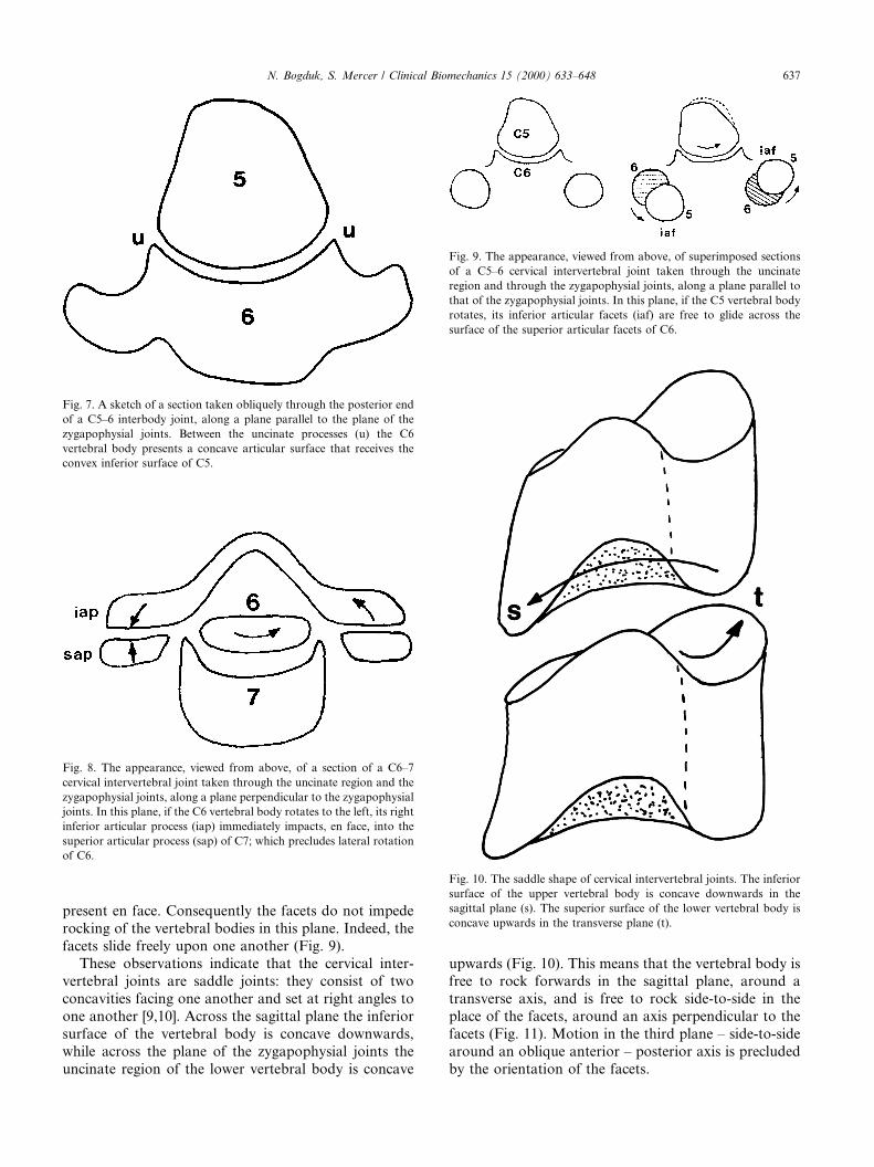
present en face. Consequently the facets do not impederocking of the vertebral bodies in this plane. Indeed, thefacets slide freely upon one another (Fig. 9).
These observations indicate that the cervical inter-vertebral joints are saddle joints: they consist of twoconcavities facing one another and set at right angles toone another [9,10]. Across the sagittal plane the inferiorsurface of the vertebral body is concave downwards,while across the plane of the zygapophysial joints theuncinate region of the lower vertebral body is concave
upwards (Fig. 10). This means that the vertebral body isfree to rock forwards in the sagittal plane, around atransverse axis, and is free to rock side-to-side in theplace of the facets, around an axis perpendicular to thefacets (Fig. 11). Motion in the third plane ± side-to-sidearound an oblique anterior ± posterior axis is precludedby the orientation of the facets.
Fig. 9. The appearance, viewed from above, of superimposed sections
of a C5±6 cervical intervertebral joint taken through the uncinate
region and through the zygapophysial joints, along a plane parallel to
that of the zygapophysial joints. In this plane, if the C5 vertebral body
rotates, its inferior articular facets (iaf) are free to glide across the
surface of the superior articular facets of C6.
Fig. 10. The saddle shape of cervical intervertebral joints. The inferior
surface of the upper vertebral body is concave downwards in the
sagittal plane (s). The superior surface of the lower vertebral body is
concave upwards in the transverse plane (t).
Fig. 7. A sketch of a section taken obliquely through the posterior end
of a C5±6 interbody joint, along a plane parallel to the plane of the
zygapophysial joints. Between the uncinate processes (u) the C6
vertebral body presents a concave articular surface that receives the
convex inferior surface of C5.
Fig. 8. The appearance, viewed from above, of a section of a C6±7
cervical intervertebral joint taken through the uncinate region and the
zygapophysial joints, along a plane perpendicular to the zygapophysial
joints. In this plane, if the C6 vertebral body rotates to the left, its right
inferior articular process (iap) immediately impacts, en face, into the
superior articular process (sap) of C7; which precludes lateral rotation
of C6.
N. Bogduk, S. Mercer / Clinical Biomechanics 15 (2000) 633±648 637
This description appears dissonant with traditionalideas that typical cervical segments exhibit ¯exion/ex-tension, lateral ¯exion, and axial rotation; but it is not.Rather it allows ¯exion/extension but stipulates that theonly other pure movement is rotation around an axisperpendicular to the facets. Since the facets are orien-tated at about 45° to the transverse plane of the verte-brae,[8] the axis of rotation is 45° from the conventionalaxes of both horizontal axial rotation and lateral ¯exion.
This geometry stipulates that conventional horizontalaxial rotation and lateral ¯exion and trigonometricprojections of the true axial rotation that occurs in thecervical spine. Moreover, it stipulates that horizontalrotation is inexorably coupled with lateral ¯exion, andvice-versa. If horizontal rotation is attempted, the infe-rior articular process must ride up this slope. As a result,the vertebra must tilt to the side of rotation. A recip-rocal combination of events obtains when lateral ¯exionis attempted. Downward movement of the ipsilateralinferior articular process is arrested by the upward fac-ing superior articular process; but is permitted if theinferior process slides backwards down the slope of thesuperior process. As a result, the vertebrae must rotateto the side of lateral ¯exion.
The axis of rotation in the plane of the zygapophysialjoints passes through the anterior end of the movingvertebral body [9,10]. This means that the anterior end
does not swing but pivots about the axis without gliding.Meanwhile, the posterior end of the vertebral body mustbe able to swing (because it is displaced from the axis).These requirements are re¯ected in the structure of theintervertebral disc.
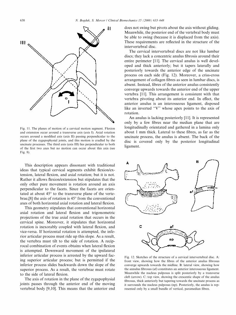
The cervical intervertebral discs are not like lumbardiscs; they lack a concentric anulus ®brosis around theirentire perimeter [11]. The cervical anulus is well devel-oped and thick anteriorly; but it tapers laterally andposteriorly towards the anterior edge of the uncinateprocess on each side (Fig. 12). Moreover, a criss-crossarrangement of collagen ®bres as seen in lumbar discs, isabsent. Instead, ®bres of the anterior anulus consistentlyconverge upwards towards the anterior end of the uppervertebra [11]. This arrangement is consistent with thatvertebra pivoting about its anterior end. In e�ect, theanterior anulus is an interosseous ligament, disposedlike an inverted ``V'' whose apex points to the axis ofrotation.
An anulus is lacking posteriorly [11]. It is representedonly by a few ®bres near the median plane that arelongitudinally orientated and gathered in a lamina onlyabout 1 mm thick. Lateral to these ®bres, as far as theuncinate process, the anulus is absent. The back of thedisc is covered only by the posterior longitudinalligament.
Fig. 12. Sketches of the structure of a cervical intervertebral disc. A:
front view, showing how the ®bres of the anterior anulus ®brosus
converge upwards towards the midline. B: lateral view, showing how
the annulus ®brosus (af) constitutes an anterior interosseous ligament.
Meanwhile the nucleus pulposus is split posteriorly by a transverse
cleft (arrow). C: top view, showing the crescentic shape of the anulus
®brosus, thick anteriorly but tapering towards the uncinate process as
it surrounds the nucleus pulposus (np). Posteriorly, the anulus is rep-
resented only by a small bundle of vertical, paramedian ®bres.
Fig. 11. The planes of motion of a cervical motion segment. Flexion
and extension occur around a transverse axis (axis I). Axial rotation
occurs around a modi®ed axis (axis II) passing perpendicular to the
plane of the zygapophysial joints, and this motion is cradled by the
uncinate processes. The third axis (axis III) lies perpendicular to both
of the ®rst two axes but no motion can occur about this axis (see
Fig. 8).
638 N. Bogduk, S. Mercer / Clinical Biomechanics 15 (2000) 633±648

This structure arises in adults through the develop-ment of transverse ®ssures across the back the cervicaldiscs [12]. The ®ssures commence, at about the age ofnine years, as clefts in the uncovertebral region. Pro-gressively they extend medially across the disc, ulti-mately to form transverse clefts by the third decade.These clefts are a normal feature of cervical discs. Whatis not known is whether they constitute some form ofprogrammed attrition of the posterior anulus, or theyarise as a result of repeated attempts at axial rotationduring early life. Whatever the explanation, their pres-ence allows, or facilitates, axial rotation.
In the absence of a posterior anulus, and given aposterior transverse cleft the posterior end of the ver-tebral body is free to swing about an anteriorly locatedaxis. As it swings, its posterior inferior border glides upand down the concavity of the uncinate processes, whileits inferior articular processes glide freely across thesuperior articular facets below (Fig. 9).
The restraints to true axial rotation of a typical cer-vical segment have not been determined by experiment.Theoretically they would appear to be tension in thecapsules of the zygapophysial joints, and tension de-veloped in the anterior anulus ®brosus as this structuretwists about the axis of rotation. If rotation is attemptedin the horizontal plane, the slope of the zygapophysialjoints is the primary impediment to rotation.
Flexion is resisted in concert by the posterior longi-tudinal ligament, the ligamentum ¯avum, the capsules ofthe zygapophysial joints, and the interspinous ligaments.Stability is maintained if either the posterior longitudi-nal ligament or the zygapophysial joints remain intact[13,14]. Extension is principally limited by the anteriorlongitudinal ligament and the anulus ®brosus, and ulti-mately by impaction of spinous processes or laminaeposteriorly.
3. Kinematics
3.1. Atlanto-occipital joint
Studies of the atlanto-occipital joint in cadaversfound the range of ¯exion±extension to be about 13°;that of axial rotation was 0°; but about 8° was possiblewhen the movement was forced [15]. A detailed radio-graphic study of cadaveric specimens [16,17] found themean ranges (SD) to be ¯exion±extension: 18:6°�0:6�,axial rotation 3:4°�0:4�, and lateral ¯exion 3:9° �0:6�. Italso revealed that when ¯exion±extension was executed,it was accompanied by negligible movements in theother planes; but when axial rotation was executed asthe primary movement, 1.5° of extension and 2.7° oflateral ¯exion occurred. However, rather than indicatinga normal or ``natural'' coupling of movements, these®gures more likely re¯ect how and where the axial tor-
que was applied to the cadavers. A di�erent degree ofcoupling could apply in vivo when axial rotation is at-tempted by the action of muscles.
Radiographic studies of the atlanto-occipital joints invivo have addressed only the range of ¯exion±extensionbecause axial rotation and lateral ¯exion are impossibleto determine accurately from plain radiographs. Moststudies agree that the average range of motion is 14±15°(Table 1). For some reason, the values reported byFielding [21] are distinctly out of character. What isconspicuous in Table 1 is the enormous variance inrange exhibited by normal individuals, which indeed ledone group of investigators [22] to refrain from o�eringeither an average or representative range. This is re-¯ected formally by the results of Lind et al. [23] in whichthe coe�cient of variation is over 100%. The reasons forthese discrepancies in ®ndings is not readily apparentfrom the original publications, but could be due to dif-ferences in the way in which occipital ¯exion/extensionwere executed and the paradoxical motion of the atlasthat di�erent strategies induce.
3.2. Atlanto-axial joint
In cadavers the atlanto-axial joints exhibit about 47°of axial rotation and some 10° of ¯exion±extension [15].Lateral ¯exion measures about 5° [24]. In living indi-viduals, plain radiography cannot be used to determineaccurately the range of axial rotation of the atlas, fordirect, top views of the moving vertebra cannot be ob-tained. Consequently, the range of axial rotation canonly be inferred from plain ®lms. For this reason, mostinvestigators using plain radiography have reportedonly the range of ¯exion±extension exhibited by the at-las (Table 2).
One approach to obtaining values of the range ofaxial rotation of the atlas has been to use biplanar ra-diography [26]. The results of such studies reveal thatthe total range of rotation (from left to right) of theocciput versus C2 is 75:2° (SD, 11.8). Moreover, axialrotation is, on the average, accompanied by 14° (SD, 6)of extension and 24° (SD, 6) of contralateral lateral¯exion. Axial rotation of the atlas is thus, not a pure
Table 1
Results of studies of normal ranges of ¯exion±extension at the
atlanto-occipital joint
Source Mean Range of motion (deg)
Range SD
Brocher [18] 14.3 0±25
Lewit and Krausova [19] 15
Markuske [20] 14.5
Fielding [21] 35
Kottke and Mundale [22] 0±22
Lind et al. [23] 14 15
N. Bogduk, S. Mercer / Clinical Biomechanics 15 (2000) 633±648 639
movement; it is coupled with a substantial degree ofextension, or in some cases ± ¯exion. The coupling arisesbecause of the passive behavior of the atlas under axialloads from the head; whether it ¯exes or extends duringaxial rotation depends on the shape of the atlanto-axialjoints and the exact orientation of any longitudinalforces acting through the atlas from the head.
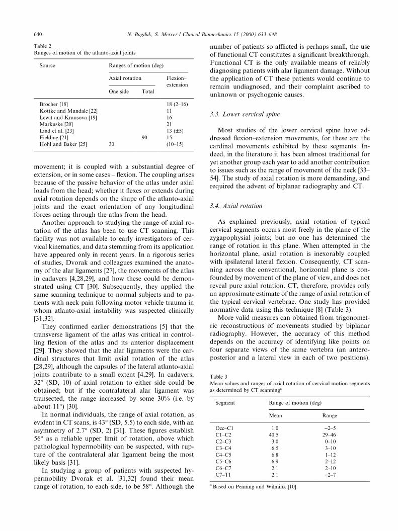
Another approach to studying the range of axial ro-tation of the atlas has been to use CT scanning. Thisfacility was not available to early investigators of cer-vical kinematics, and data stemming from its applicationhave appeared only in recent years. In a rigorous seriesof studies, Dvorak and colleagues examined the anato-my of the alar ligaments [27], the movements of the atlasin cadavers [4,28,29], and how these could be demon-strated using CT [30]. Subsequently, they applied thesame scanning technique to normal subjects and to pa-tients with neck pain following motor vehicle trauma inwhom atlanto-axial instability was suspected clinically[31,32].
They con®rmed earlier demonstrations [5] that thetransverse ligament of the atlas was critical in control-ling ¯exion of the atlas and its anterior displacement[29]. They showed that the alar ligaments were the car-dinal structures that limit axial rotation of the atlas[28,29], although the capsules of the lateral atlanto-axialjoints contribute to a small extent [4,29]. In cadavers,32° (SD, 10) of axial rotation to either side could beobtained; but if the contralateral alar ligament wastransected, the range increased by some 30% (i.e. byabout 11°) [30].
In normal individuals, the range of axial rotation, asevident in CT scans, is 43° (SD, 5.5) to each side, with anasymmetry of 2:7° (SD, 2) [31]. These ®gures establish56° as a reliable upper limit of rotation, above whichpathological hypermobility can be suspected, with rup-ture of the contralateral alar ligament being the mostlikely basis [31].
In studying a group of patients with suspected hy-permobility Dvorak et al. [31,32] found their meanrange of rotation, to each side, to be 58°. Although the
number of patients so a�icted is perhaps small, the useof functional CT constitutes a signi®cant breakthrough.Functional CT is the only available means of reliablydiagnosing patients with alar ligament damage. Withoutthe application of CT these patients would continue toremain undiagnosed, and their complaint ascribed tounknown or psychogenic causes.
3.3. Lower cervical spine
Most studies of the lower cervical spine have ad-dressed ¯exion±extension movements, for these are thecardinal movements exhibited by these segments. In-deed, in the literature it has been almost traditional foryet another group each year to add another contributionto issues such as the range of movement of the neck [33±54]. The study of axial rotation is more demanding, andrequired the advent of biplanar radiography and CT.
3.4. Axial rotation
As explained previously, axial rotation of typicalcervical segments occurs most freely in the plane of thezygapophysial joints; but no one has determined therange of rotation in this plane. When attempted in thehorizontal plane, axial rotation is inexorably coupledwith ipsilateral lateral ¯exion. Consequently, CT scan-ning across the conventional, horizontal plane is con-founded by movement of the plane of view, and does notreveal pure axial rotation. CT, therefore, provides onlyan approximate estimate of the range of axial rotation ofthe typical cervical vertebrae. One study has providednormative data using this technique [8] (Table 3).
More valid measures can obtained from trigonomet-ric reconstructions of movements studied by biplanarradiography. However, the accuracy of this methoddepends on the accuracy of identifying like points onfour separate views of the same vertebra (an antero-posterior and a lateral view in each of two positions).
Table 3
Mean values and ranges of axial rotation of cervical motion segments
as determined by CT scanninga
Segment Range of motion (deg)
Mean Range
Occ±C1 1.0 )2±5
C1±C2 40.5 29±46
C2±C3 3.0 0±10
C3±C4 6.5 3±10
C4±C5 6.8 1±12
C5±C6 6.9 2±12
C6±C7 2.1 2±10
C7±T1 2.1 )2±7
a Based on Penning and Wilmink [10].
Table 2
Ranges of motion of the atlanto-axial joints
Source Ranges of motion (deg)
Axial rotation Flexion±
extension
One side Total
Brocher [18] 18 (2±16)
Kottke and Mundale [22] 11
Lewit and Krausova [19] 16
Markuske [20] 21
Lind et al. [23] 13 (�5)
Fielding [21] 90 15
Hohl and Baker [25] 30 (10±15)
640 N. Bogduk, S. Mercer / Clinical Biomechanics 15 (2000) 633±648

Accuracy in this process is not easy to achieve [16].Nevertheless, one study [26] has provided normativedata using this technique (Table 4). What is noticeablefrom these data is that biplanar radiography reveals asomewhat more generous range of axial rotation thandoes CT, but that this rotation is coupled with a lateral¯exion of essentially the same magnitude.
By applying trigonometric corrections to the dataobtained from CT and biplanar radiography, the rangeof axial rotation in the plane of the zygapophysial jointscan be calculated (see Appendix A). If the plane of thejoints is orientated at an angle of h° to the horizontalplane; and if a is the rotation in the horizontal plane,and u is the rotation in the plane of the facets,tan a� tan / cos h. Allowing for a 45° slope of the cer-vical facets, for a range of horizontal rotation of 6° therange of rotation in the plane of the zygapophysial jointswould be about 8°.
3.5. Flexion±extension
Early studies of the cervical spine examined the rangeof movement of the entire neck, typically by applyinggoniometers to the head [39±41,44,51]. Fundamentally,however, such studies describe the range of movement ofthe head. Although they provide implicit data on theglobal function of the neck, they do not reveal whatactually is happening inside the neck.
Some investigators studied cadavers [42,45,50]. Suchstudies are an important ®rst iteration for they establishwhat might be expected when individual segments cometo be studied in vivo, and how it might best be mea-sured. However, cadaver studies are relatively arti®cial;the movement of skeletons without muscles does notaccurately re¯ect how intact, living individuals move.
Investigators recognized that for a proper compre-hension of cervical kinematics radiographic studies ofnormal individuals were required; [32±38,43±48,52±54]and a large number of investigators produced whatmight be construed as normative data on the range ofmotion of individual cervical segments and the neck as awhole [7,22,33±35,37,38,46±48].
What is conspicuous about these data, however, isthat while ranges of values were sometimes reported,standard deviations were not. It seems that most of thesestudies were undertaken in a era before the advent ofstatistical and epidemiological rigour. Two early studies[36,46] provided raw data from which means and stan-dard deviations could be calculated, and two recentstudies [23, 52] provided data properly described instatistical terms (Table 5).
The early studies of cervical motion were also marredby lack of attention to the reliability of the techniqueused; inter-observer and intra-observer errors were notreported. This leaves unknown the extent to which ob-server errors and technical errors compromise the ac-curacy of the data reported. Only those studiesconducted in recent years specify the inter-observer er-ror of their techniques; [23,52] so only their data can beconsidered acceptable.
The implication of collecting normative data is thatsomehow it might be used diagnostically to determineabnormality. Unfortunately, without means and stan-dard deviations and without values for observer errors,normative data is at best illustrative, and cannot beadopted for diagnostic purposes. To declare an indi-vidual or a segment to be abnormal, an investigatormust clearly be able to calculate the probability of agiven observation constituting a normal value, and mustdetermine whether or not technical errors have biasedthe observation.
One study has pursued this application using reliableand well-described data [52]. For active and passive
Table 4
Normal ranges of motion of cervical spine in axial rotation, and ranges
of coupled motions, as determined by Biplanar radiographya
Segment Coupled movement
Axial
rotation
mean degrees
(SD)
Flexion/
extension
mean degrees
(SD)
Lateral
¯exion mean
degrees
(SD)
Occ±C2 75 (12) )14 (6) )2 (6)
C2±3 7 (6) 0 (3) )2 (8)
C3±4 6 (5) )3 (5) 6 (7)
C4±5 4 (6) )2 (4) 6 (7)
C5±6 5 (4) 2 (3) 4 (8)
C6±7 6 (3) 3 (3) 3 (7)
a Based on Mimura et al. [26].
Table 5
Results of those studies of cervical ¯exion and extension that reported both mean values and (standard deviations)
Source Number Mean range and standard deviation of motion (°)
C2±3 C3±4 C4±5 C5±6 C6±7
Aho et al. [36] 15 12 (5) 15 (7) 22 (4) 28 (4) 15 (4)
Bhalla and Simmons [46] 20 9 (1) 15 (2) 23 (1) 19 (1) 18 (3)
Lind et al. [23] 70 10 (4) 14 (6) 16 (6) 15 (8) 11 (7)
Dvorak et al. [52] 28 10 (3) 15 (3) 19 (4) 20 (4) 19 (4)
N. Bogduk, S. Mercer / Clinical Biomechanics 15 (2000) 633±648 641
cervical ¯exion, mean values and standard deviationswere determined for the range of motion of every cer-vical segment, using a method of stated reliability.Furthermore, it was claimed that symptomatic patientscould be identi®ed on the basis of hypermobility orhypomobility [52]. However, the normal range adoptedin this study was one standard deviation either side ofthe mean [52]. This is irregular and illusory.
It is more conventional to adopt the two standarddeviation range as the normal range. This conventionestablishes a range within which 96% of the asymp-tomatic population lies; only 2% of the normal popu-lation will fall above these limits, and only 2% will fallbelow. Adopting a one standard deviation range classi-®es only 67% of the normal population within the limits,leaving 33% of normal individuals outside the range.This means that any population of putatively abnormalindividuals will be ``contaminated'' with 33% of thenormal population. This reduces the speci®city of thetest, and increases its false-positive rate.
3.6. Directional and temporal consistency
Regardless of how fashionable it may have been tostudy ranges of motion of the neck, and regardless ofhow genuine may have been the intent and desire ofearly investigators to derive data that could be used todetect abnormalities, a de®nitive study has appearedwhich has put paid to all previous studies and rendersirrelevant any further studies of cervical motion usingconventional radiographic techniques. No longer areany of the earlier data of any great use.
Van Mameren and colleagues [3] used an exquisitetechnique to study cervical motion in ¯exion and exten-sion in normal volunteers. High-speed cineradiographswere taken to produce upto 25 exposures fore each ex-cursion form full ¯exion to full extension, or from fullextension to full ¯exion. When printed and converted toa static view, each frame provided an image equal inquality and resolution to a conventional lateral radio-graph of the cervical spine. These images could be reli-ably digitized, and each could be compared to any otherin the series in order to reconstruct and plot the patternof motion either algebraically or geometrically. Theirtechnique di�ered from video¯uoroscopy in that insteadof viewing dynamic ®lms, each frame was fastidiouslystudied as a static ®lm and compared to every other.
Ten subjects undertook ¯exion from full extension,and also extension from full ¯exion. The experimentswere repeated two weeks and 10 weeks after the ®rstobservation. These studies allowed the ranges of motionof individual cervical segments to be studied andcorrelated against total range of motion of the neck,and against the direction in which movement wasundertaken. Moreover, the stability of the observations
over time could be determined. The results are mostrevealing.
The maximum range of motion of a given cervicalsegment is not necessarily re¯ected by the range appar-ent when the position of the vertebra in full ¯exion iscompared to its position in full extension. Often themaximum range of motion is exhibited at some stageduring the excursion but prior to the neck reaching its®nal position. In other words, a vertebra may reach itsmaximum range of ¯exion, but as the neck continuestowards ``full ¯exion'', that vertebra actually reverses itsmotion, and extends slightly. This behavior is particu-larly apparent at upper cervical segments: Occ±C1, C1±2. A consequence of this behavior is that the total rangeof motion of the neck is not the arithmetic sum of itsintersegmental ranges of motion.
A second result is that segmental range of motiondi�ers according to whether the motion is executed from¯exion to extension or from extension to ¯exion. At thesame sitting, in the same individual, di�erences of 5±15°can be recorded in a single segment, particularly at Occ±C1 and C6±7. The collective e�ect of these di�erences,segment by segment, can result in di�erences of 10±30°in total range of cervical motion.
There is no criterion by which to decide whichmovement strategy should be preferred. It is not aquestion of standardizing a convention as to which di-rection of movement should (arbitrarily) be recognizedas standard. Rather, the behavior of cervical motionsegments simply raises a caveat that no single observa-tion de®nes a unique range of movement. Since the di-rection of movement used can in¯uence the observedrange, an uncertainty arises. Depending on the segmentinvolved, an observer may record a range of movementthat may be ®ve or even 15° less or more the range ofwhich the segment is actually capable. By the same to-ken, claims of therapeutic success in restoring a range ofmovement must be based on ranges in excess of thisrange of uncertainty.
The third result is that ranges of movement are notstable with time. A di�erence in excess of 5° for the samesegment in the same individual can be recorded if theyare studied by the same technique but on another oc-casion, particular at segments Occ±C1, C5±6 and C6±7.Rhetorically, the question becomes ± which observationwas the true normal? The answer is that, within an in-dividual, normal ranges do not come as a single value;they vary with time, and it is variance and the range ofvariation that constitute the normal behavior, not asingle value. The implication is that a single observationof a range must be interpreted carefully and can be usedfor clinical purposes only with this variance in mind. Alower range today, a higher range tomorrow, or vice-versa, could be only the normal, diurnal variation andnot something attributable to a disease or to a thera-peutic intervention.
642 N. Bogduk, S. Mercer / Clinical Biomechanics 15 (2000) 633±648
3.7. Cadence
Commentators in the past have maintained that asthe cervical spine as a whole moves there must a setorder in which the individual cervical vertebra move, i.e.there must be a normal pattern of movement, or ca-dence. Buonocore et al. [55] asserted that ``The spinousprocesses during ¯exion separate in a smooth fan-likeprogression. Flexion motion begins in the upper cervicalspine. The occiput separates smoothly from the poste-rior arch of the atlas, which then separates smoothlyfrom the spine of the axis, and so on down the spine.The interspaces between the spinous processes becomegenerally equal in complete ¯exion. Most important, thespinous processes separate in orderly progression. Inextension the spines rhythmically approximate eachother in reverse order to become equidistant in fullextension.''
This idealized pattern of movement is not what nor-mally occurs. During ¯exion and extension, the motionof the cervical vertebrae is regular but is not simple; it iscomplex and counter-intuitive. Nor is it easy to describe.Van Mameren [56] undertook a detailed analysis of hiscineradiographs of 10 normal individuals performing¯exion and extension of the cervical spine. His descrip-tions are complex, re¯ecting the intricacies of movementof individual segments. However, a general pattern canbe discerned.
Flexion is initiated in the lower cervical spine (C4±7).Within this block, and during this initial phase of mo-tion, the C6±7 segment regularly makes its maximumcontribution, before C5±6, followed by C4±5. That ini-tial phase is followed by motion at C0±C2, and then byC2±3 and C3±4. During this middle phase, the order ofcontribution of C2±3 and C3±4 is variable. Also duringthis phase, a reversal of motion (i.e. slight extension)occurs at C6±7 and, in some individuals, at C5±6. The®nal phase of motion again involves the lower cervicalspine (C4±7), and the order of contribution of individualsegments is C4±5, C5±6, and C6±7. During this phase,C0±C2 typical exhibits a reversal of motion (i.e. exten-sion). Flexion is thus initiated and terminated by C6±7.It is never initiated at mid cervical levels. C0±C2 andC2±3, C3±4 contribute maximally during the middlephase of motion, but in variable order.
Extension is initiated in the lower cervical spine (C4±7), but the order of contribution of individual segmentsis variable. This is followed by the start of motion atC0±C2 and at C2±C4. Between C2 and C4 the order ofcontribution is quite variable. The terminal phase ofextension is marked by a second contribution by C4±7,in which the individual segments move in the regularorder ± C4±5, C5±6, C6±7. During this phase the con-tribution of C0±C2 reaches its maximum.
The fact that this pattern of movements is repro-ducible is remarkable. Studied on separate occasions,
individuals consistently show the same pattern with re-spect to the order of maximum contribution of indi-vidual segments. Consistent between individuals is theorder of contribution of the lower cervical spine and itscomponent segments during both ¯exion and extension.Such variation as does occur between individuals appliesonly to the mid cervical levels: C2±C4.
3.8. Instantaneous centres of rotation
Having noted the lack of utility of range of motionstudies, some investigators explored the notion ofquality of motion of the cervical vertebrae. They con-tended that although perhaps not revealed by abnormalranges of motion, abnormalities of the cervical spinemight be revealed by abnormal patterns of motionwithin individual segments.
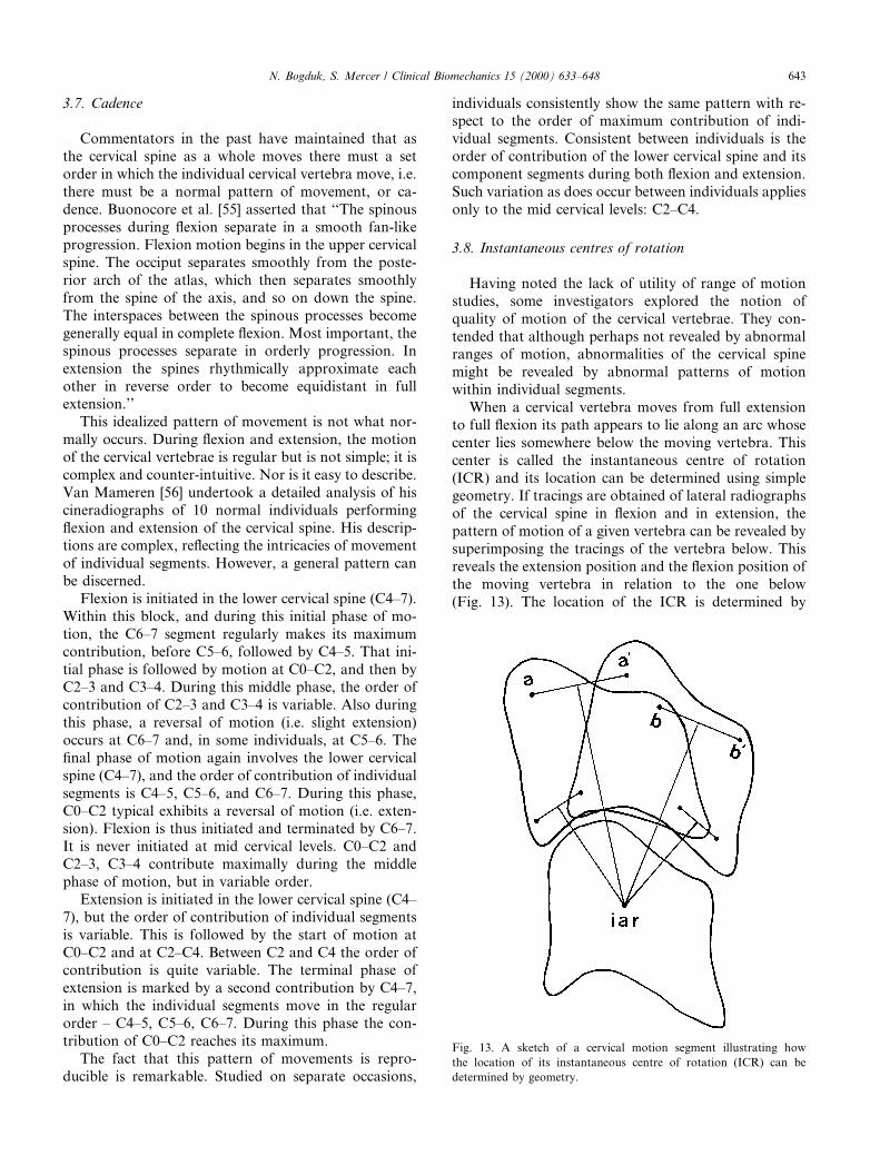
When a cervical vertebra moves from full extensionto full ¯exion its path appears to lie along an arc whosecenter lies somewhere below the moving vertebra. Thiscenter is called the instantaneous centre of rotation(ICR) and its location can be determined using simplegeometry. If tracings are obtained of lateral radiographsof the cervical spine in ¯exion and in extension, thepattern of motion of a given vertebra can be revealed bysuperimposing the tracings of the vertebra below. Thisreveals the extension position and the ¯exion position ofthe moving vertebra in relation to the one below(Fig. 13). The location of the ICR is determined by
Fig. 13. A sketch of a cervical motion segment illustrating how
the location of its instantaneous centre of rotation (ICR) can be
determined by geometry.
N. Bogduk, S. Mercer / Clinical Biomechanics 15 (2000) 633±648 643
drawing the perpendicular bisectors of intervals con-necting like points on the two positions of the movingvertebra. The point of intersection of the perpendicularbisectors marks the location of the ICR (Fig. 13).
The ®rst normative data on the ICRs of the cervicalspine were provided by Penning [9,37,43]. He foundthem to be located in di�erent positions for di�erentcervical segments. At lower cervical levels, the ICRswere located close to the intervertebral disc of the seg-ment in question but, at higher segmental levels the ICRwas located substantially lower than this position.
A problem emerged, however, with Penning's data[9,37,43]. Although he displayed the data graphically hedid not provide any statistical parameters such as themean location and variance; nor did he explain howICRs from di�erent individuals with vertebra of di�er-ent sizes were plotted onto a single, common silhouetteof the cervical spine. This process requires some form ofnormalization but this was not described by Penning[9,37,43].
Subsequent studies pursued the accurate determi-nation of the location of the ICRs of the cervicalspine. First, it was found that the technique used byPenning [9,37,43,49] to plot ICRs was insu�cientlyaccurate; the basic ¯aw lay in how well the images ofthe cervical vertebrae could be traced [57]. Subse-quently, an improved technique with smaller inter-observer errors was developed [58] and was used todetermine the location of ICRs in a sample of 40normal individuals [59].
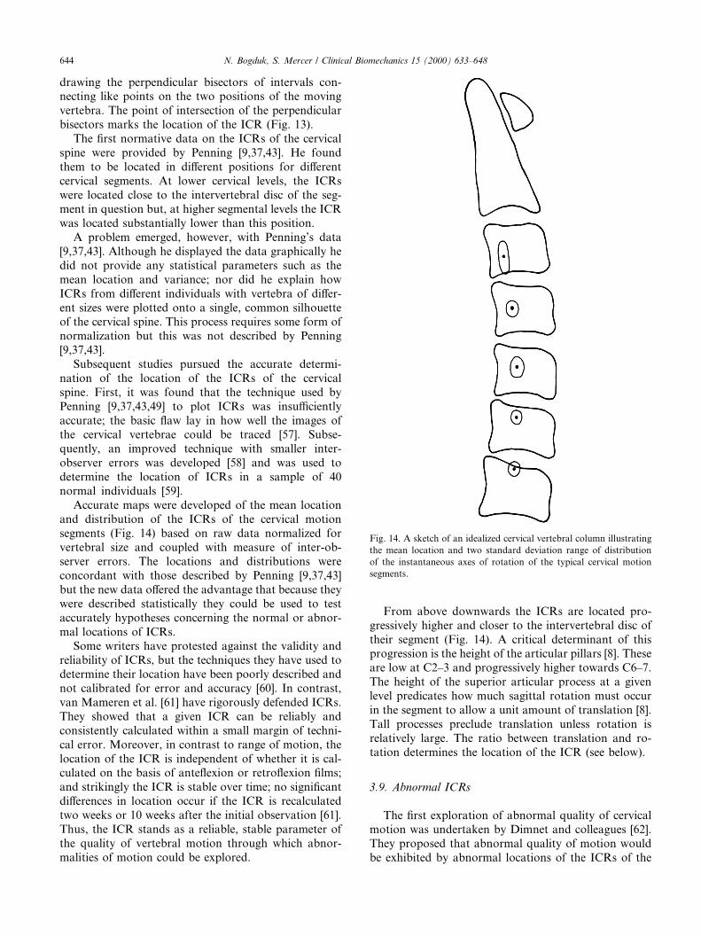
Accurate maps were developed of the mean locationand distribution of the ICRs of the cervical motionsegments (Fig. 14) based on raw data normalized forvertebral size and coupled with measure of inter-ob-server errors. The locations and distributions wereconcordant with those described by Penning [9,37,43]but the new data o�ered the advantage that because theywere described statistically they could be used to testaccurately hypotheses concerning the normal or abnor-mal locations of ICRs.
Some writers have protested against the validity andreliability of ICRs, but the techniques they have used todetermine their location have been poorly described andnot calibrated for error and accuracy [60]. In contrast,van Mameren et al. [61] have rigorously defended ICRs.They showed that a given ICR can be reliably andconsistently calculated within a small margin of techni-cal error. Moreover, in contrast to range of motion, thelocation of the ICR is independent of whether it is cal-culated on the basis of ante¯exion or retro¯exion ®lms;and strikingly the ICR is stable over time; no signi®cantdi�erences in location occur if the ICR is recalculatedtwo weeks or 10 weeks after the initial observation [61].Thus, the ICR stands as a reliable, stable parameter ofthe quality of vertebral motion through which abnor-malities of motion could be explored.
From above downwards the ICRs are located pro-gressively higher and closer to the intervertebral disc oftheir segment (Fig. 14). A critical determinant of thisprogression is the height of the articular pillars [8]. Theseare low at C2±3 and progressively higher towards C6±7.The height of the superior articular process at a givenlevel predicates how much sagittal rotation must occurin the segment to allow a unit amount of translation [8].Tall processes preclude translation unless rotation isrelatively large. The ratio between translation and ro-tation determines the location of the ICR (see below).
3.9. Abnormal ICRs
The ®rst exploration of abnormal quality of cervicalmotion was undertaken by Dimnet and colleagues [62].They proposed that abnormal quality of motion wouldbe exhibited by abnormal locations of the ICRs of the
Fig. 14. A sketch of an idealized cervical vertebral column illustrating
the mean location and two standard deviation range of distribution
of the instantaneous axes of rotation of the typical cervical motion
segments.
644 N. Bogduk, S. Mercer / Clinical Biomechanics 15 (2000) 633±648

cervical motion segment. In a small study of six symp-tomatic patients they found that in patients with neckpain, the ICRs exhibited a wider scatter than in normalindividuals. However, they compared samples of pa-tients and not individual patients; their data did notreveal in a given patient which and how many ICRswere normal or abnormal or to what extent.
A similar study was pursued by Mayer et al. [63] whoclaimed that patients with cervical headache exhibitedabnormal ICRs of the upper cervical segments. How-ever, their normative data were poorly described withrespect to ranges of distribution; nor was the accuracydescribed of their technique used to determine bothnormal and abnormal centres.
Nevertheless, these two studies augured that if reli-able and accurate techniques were to be used it waslikely that abnormal patterns of motion could be iden-ti®ed in patients with neck pain, in the form of abnormallocations of their ICRs. This contention was formallyinvestigated.
Amevo et al. [64] studied 109 patients with post-traumatic neck pain. Flexion±extension radiographswere obtained and ICRs were determined for all seg-ments from C2±3 to C6±7 where possible. These loca-tions were subsequently compared with previouslydetermined normative data [59]. It emerged that 77% ofthe patients with neck pain exhibited an abnormallylocated centre at one segmental level at least. This re-lationship between axis location and pain was highlysigni®cant statistically (Table 6); there was clearly arelationship between pain and abnormal patterns ofmotion.
Further analysis revealed that most abnormal centreswere at upper cervical levels, notably at C2±3 and C3±4.However, there was no evident relationship between thesegmental level of an abnormally located ICR and thesegment found to be symptomatic on the basis ofprovocation discography or cervical zygapophysial jointblocks [64]. This suggested that perhaps abnormal ICRswere not caused by intrinsic abnormalities of a painfulsegment but were secondary to some factor such asmuscle spasm. However, this contention could not beexplored because insu�cient numbers of patients had
undergone investigation of upper cervical segments withdiscography or joint blocks.
3.10. Biological basis
Mathematical analysis shows that the location of anICR is a function of three basic variables: the amplitudeof rotation (h) of a segment, its translation (T), and thelocation of its center of rotation (CR) [65]. In mathe-matical terms, with respect to any universal coordinatesystem �X ; Y �, the location of the ICR is de®ned by theequations:
XICR � XCR � T =2;
YICR � YCR ÿ T=�2 tan�h=2��;where (XICR, YICR) is the location of the ICR, and (XCR,YCR) is the location of the center or reaction.
In this context, the center of reaction is a point on theinferior endplate of the moving vertebra where com-pression loads on that vertebra are maximal, or themathematical average point where compression loadsare transmitted from the vertebra to the underlying disc.It is also the pivot point around which the vertebrarocks under compression, or around which the vertebrawould rotate in the absence of any shear forces that addtranslation to the movement [65].
The equations dictate that the normal location, andany abnormal location, of an ICR is governed by the nete�ect of compression forces, shear forces and momentsacting on the moving segment. The compression forcesexerted by muscles and by gravity, and the resistance tocompression exerted by the facets and disc of the seg-ment determine the location of the center of reaction.The shear forces exerted by gravity and muscles, and theresistance to these forces exerted by the intervertebraldisc and facets determine the magnitude of translation.The moments exerted by gravity and by muscles, and theresistance to these exerted by tension in ligaments, jointcapsules and the anulus ®brosus determine the ampli-tude of rotation.
These relationships allow the location of an ICR tobe interpreted in anatomical and pathological terms.Displacement of an ICR from its normal location canoccur only if the normal balance of compression loads,shear loads, or moments is disturbed. Moreover, dis-placements in particular directions can occur only as aresult of certain, ®nite, combinations of disturbances tothese variables. For example, the ICR equations dictatethat downward and backward displacement of an ICRcan occur only if there is a simultaneous posterior dis-placement of the center or reaction and a reduction inrotation [65]. Mechanically, this combination of distur-bances is most readily achieved by increased posteriormuscle tension. On one hand, this tension eccentricallyloads the segment in compression, displacing the center
Table 6
Chi-squared analysis of the relationship between the presence of pain
and the location of instantaneous centres of rotationa
Instantaneous centre of rotation
Normal Abnormal
Pain 31 78 109
No painb 44 2 46
75 80 155
a X 2 � 58:5; df � 1; P < 0:001.b n� 46, and by de®nition 96% of these (44) exhibit normal ICRs.
Based on Amevo et al. [64].
N. Bogduk, S. Mercer / Clinical Biomechanics 15 (2000) 633±648 645
or reaction posteriorly; meanwhile, the increased tensionlimits forward ¯exion and reduces angular rotation. Anabnormal ICR, displaced downwards and backwards is,therefore, a strong sign of increased posterior muscletension. Although the tension is not recorded electr-omyographically or otherwise, its presence can be in-ferred from mathematical analysis of the behavior of thesegment. Although the tension is not ``seen'', the e�ectsof its force are manifest (just as the presence of an in-visible planet can be detected by the gravitational e�ectsit exerts on nearby celestial bodies).
Upward displacement of an ICR can occur only ifthere is a decrease in translation, or an increase in ro-tation, all other variables being normal. This type ofdisplacement of displacement is most readily produced if¯exion±extension is produced in the absence of shearforces, i.e. the segment is caused to rotate only by forcesacting essentially parallel to the long axis of the cervicalspine. This type of movement occurs during the earlyphases of whiplash [66], and will explored in a laterreview.
3.11. Applications
A major, but clinically unexciting, application ofICRs is in the ®eld of biomechanical modeling. Achallenge for any model is validation. For a model tooperate, estimates need to be applied of the forces actingon the vertebrae, such as the compression sti�ness of thediscs, tension in the capsules and ligaments, and theaction of muscles. But these estimates usually stem froma variety of separate sources. There is no guarantee thatwhen combined into a single model they accurately re-¯ect what happens in a normal cervical spine. One test,however, is to determine the ICRs produced by themodel as the neck moves.
If the estimates of forces are wrong, their net e�ectwill be to execute movements about abnormal ICRs.Conversely, if the resultant movements occur aboutnormal centres of movement, investigators can be con-®dent that their estimates of forces are realistic. Al-though possible, it seems highly improbable thatincorrect estimates would accidentally combine to pro-duce correct ICRs at all segments simultaneously.
This approach to validation has been used to goode�ect in the most detailed model of the cervical spinedeveloped to date [67]. The model generates normalICRs at lower cervical segments; but errors obtain atupper cervical segments. This calls for a re®nement ofthe forces exerted across upper cervical segments, interms of the magnitude or direction of the vectors of theupper cervical muscles, or the details of upper cervicalvertebral geometry.
More relevant clinically is the potential application ofICRs in cervical diagnosis. To date, it has been ®rmlyestablished that abnormal ICRs correlate with neck pain
[64]. However, the abnormal ICRs do not necessarily lieat the symptomatic segment. Therefore, they do notre¯ect damage to that segment. Rather, abnormal ICRsseem to re¯ect secondary e�ects of pain.
Theoretically, it is possible to apply the ICR equa-tions to resolve, case by case, whether an abnormal ICRis due to muscle spasm, impairment of ligament tension,or altered compression sti�ness of the disc. The neces-sary studies, however, have not yet been conducted. Forinterested clinicians, this ®eld remains open.
Appendix A. The relationship between horizontal rotation
and rotation in the plane of the cervical facets
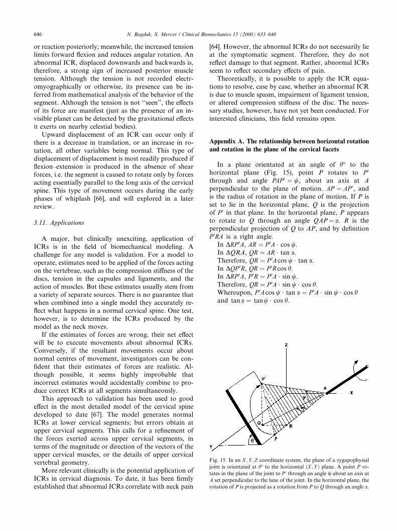
In a plane orientated at an angle of h° to thehorizontal plane (Fig. 15), point P rotates to P 0
through and angle PAP 0 � w, about an axis at Aperpendicular to the plane of motion. AP � AP 0, andis the radius of rotation in the plane of motion. If P isset to lie in the horizontal plane, Q is the projectionof P 0 in that plane. In the horizontal plane, P appearsto rotate to Q through an angle QAP� a. R is theperpendicular projection of Q to AP, and by de®nitionP 0RA is a right angle.
In DRP 0A, AR � P 0A � cos w.In DQRA, QR � AR � tan a.Therefore, QR � P 0Acos w � tan a.In DQP 0R, QR � P 0R cos h.In DRP 0A, P 0R � P 0A � sin w.Therefore, QR � P 0A � sin w � cos h.Whereupon, P 0Acos w � tan a � P 0A � sin w � cos hand tana � tanw � cos h.
Fig. 15. In an X ; Y ;Z coordinate system, the plane of a zygapophysial
joint is orientated at h° to the horizontal �X ; Y � plane. A point P ro-
tates in the plane of the joint to P 0 through an angle w about an axis at
A set perpendicular to the lane of the joint. In the horizontal plane, the
rotation of P is projected as a rotation from P to Q through an angle a.
646 N. Bogduk, S. Mercer / Clinical Biomechanics 15 (2000) 633±648
References
[1] Koebke J, Brade H. Morphological and functional studies on the
lateral joints of the ®rst and second cervical vertebrae in man.
Anat Embryol 1982;164:265±75.
[2] Mercer S, Bogduk N. Intra-articular inclusions of the cervical
synovial joints. Brit J Rheumatol 1993;32:705±10.
[3] Van Mameren H, Drukker J, Sanches H, Beursgens J. Cervical
spine motion in the sagittal plane. (I). Range of motion of
actually performed movements, an X-ray cinematographic study.
Eur J Morph 1990;28:47±68.
[4] Crisco JJ, Oda T, Panjabi MM, Bue� HU, Dvorak J, Grob D.
Transections of the C1±C2 joint capsular ligaments in the
cadaveric spine. Spine 1991;16:S474±9.
[5] Fielding JW, Cochran GVB, Lawsing JF, Hohl M. Tears of the
transverse ligament of the atlas. J Bone Joint Surg
1974;56A:1683±91.
[6] Bogduk N, Major GAC, Carter J. Lateral subluxation of the atlas
in rheumatoid arthritis: a case report and post-mortem study.
Ann Rheum Dis 1984;43:341±6.
[7] Mestdagh H. Morphological aspects and biomechanical proper-
ties of the vertebro-axial joint (C2-C3). Acta Morphol Neerl-
Scand 1976;14:19±30.
[8] Nowitzke A, Westaway M, Bogduk N. Cervical zygapophyseal
joints: geometrical parameters and relationship to cervical kine-
matics. Clin Biomech 1994;9:342±8.
[9] Penning L. Di�erences in anatomy, motion, development and
aging of the upper and lower cervical disk segments. Clin
Biomech 1988;3:37±47.
[10] Penning L, Wilmink JT. Rotation of the cervical spine. A CT
study in normal subjects. Spine 1987;12:732±8.
[11] Mercer S, Bogduk N. The ligaments and anulus ®brosus of
human adult cervical intervertebral discs. Spine 1999;24:619±
26.
[12] Oda J, Tanaka H, Tsuzuki N. Intervertebral disc changes with
aging of human cervical vertebra. From the neonate to the
eighties. Spine 1988;13:1205±11.
[13] Panjabi MM, White AA, Johnson RM. Cervical spine mechanics
as a function of transection of components. J Biomech
1975;8:327±36.
[14] White AA, Johnson RM, Panjabi MM, Southwick WO. Biome-
chanical analysis of clinical stability in the cervical spine. Clin
Orthop 1975;109:85±96.
[15] Werne S. The possibilities of movement in the craniovertebral
joints. Acta Orthop Scandinav 1958;28:165±73.
[16] Worth D. Cervical Spine Kinematics. PhD thesis, Flinders
University of South Australia, 1985.
[17] Worth DR, Selvik G. Movements of the craniovertebral joints.
In: Grieve G, editor. Modern manual therapy of the vertebral
column. Edinburgh: Churchill Livingstone, 1986:53.
[18] Brocher JEW. Die Occipito-Cervical-Gegend. Eine diagnostische
pathogenetische Studie. Stuttgart: Georg Thieme Verlag, 1955
[cited by van Mameren et al. [47]].
[19] Lewit K, Krausova L. Messungen von Vor- and Ruckbeuge in
den Kopfgelenken. Fortsch R�ontgenstr 1963;99:538±43.
[20] Markuske H. Untersuchungen zur Statik und Dynamik der
kindlichen Halswirbels�aule: Der Aussagewert seitlicher R�ontge-
naufnahmen. Die Wirbels�aule in Forschung und Praxis 50, 1971
[cited by van Mameren et al. [47]].
[21] Fielding JW. Cineroentgenography of the normal cervical spine.
J Bone Joint Surg 1957;39A:1280±8.
[22] Kottke FJ, Mundale MO. Range of mobility of the cervical spine.
Arch Phys Med Rehab 1959;40:379±86.
[23] Lind B, Sihlbom H, Nordwall A, Malchau H. Normal ranges of
motion of the cervical spine. Arch Phys Med Rehabil
1989;70:692±5.
[24] Dankmeijer J, Rethmeier BJ. The lateral movement in the
atlanto-axial joints and its clinical signi®cance. Acta Radiol
1943;24:55±66.
[25] Hohl M, Baker HR. The atlanto-axial joint. J Bone Joint Surg
1964;46A:1739±52.
[26] Mimura M, Moriya H, Watanabe T, Takahashi K, Yamagata M,
Tamaki Tl. Three-dimensional motion analysis of the cervical
spine with special reference to the axial rotation. Spine
1989;14:1135±9.
[27] Saldinger P, Dvorak J, Rahn BA, Perren SM. Histology of the
alar and transverse ligaments. Spine 1990;15:257±61.
[28] Dvorak J, Panjabi MM. Functional anatomy of the alar
ligaments. Spine 1987;12:183±9.
[29] Dvorak J, Schneider E, Saldinger P, Rahn B. Biomechanics of the
craniocervical region: the alar and transverse ligaments. J Orthop
Res 1988;6:452±61.
[30] Dvorak J, Panjabi M, Gerber M, Wichmann W. CT-functional
diagnostics of the rotatory instability of upper cervical spine. 1.
An experimental study on cadavers. Spine 1987;12:197±205.
[31] Dvorak J, Hayek J, Zehnder R. CT-functional diagnostics of the
rotatory instability of the upper cervical spine. Part 2. An
evaluation on healthy adults and patients with suspected insta-
bility. Spine 1987;12:725±31.
[32] Dvorak J, Penning L, Hayek J, Panjabi MM, Zehnder Rl.
Functional diagnostics of the cervical spine using computer
tomography. Neuroradiology 1988;30:132±7.
[33] Bakke SN. R�ontgenologische Beobachtungen uber die Bewegun-
gen der Wirbels�aule. Acta Radiol Suppl 1931;13:1±76.
[34] de Seze S. Etude radiologique de la dynamique cervicale dans la
plan sagittale. Rev Rhum 1951;3:111±6.
[35] Buetti-Bauml C. Funcktionelle R�oentgendiagnostik der Halswir-
belsaule. Stuttgart: Georg Thieme Verlag, 1954 [cited by van
Mameren et al. [47], Aho et al. [31] and Dvorak et al. [40]].
[36] Aho A, Vartianen O, Salo O. Segmentary antero-posterior
mobility of the cervical spine. Annales Medicinae Internae
Fenniae 1955;44:287±99.
[37] Penning L. Funktioneel r�ontgenonderzoek bij degeneratieve en
traumatische afwijikingen der laag-cervicale bewingssegmenten.
thesis, Reijuniversiteit Groningen, Groningen, The Netherlands,
1960.
[38] Zeitler E, Markuske H. R�ontegenologische Bewegungsanalyse
der Halswirbelsaule bei gesunden Kinden. Forstschr R�ontgestr
1962;96:87 [cited by van Mameren et al. [47]].
[39] Ferlic D. The range of motion of the ``normal'' cervical spine.
Bull Johns Hopkins Hosp 1962;110:59±65.
[40] Bennett JG, Bergmanis LE, Carpenter JK, Skowund HV. Range
of motion of the neck. Phys Ther 1963;43:45±7.
[41] Schoening HA, Hanna V. Factors related to cervical spine
mobility, Part 1. Arch Phys Med Rehabil 1964;45:602±9.
[42] Ball J, Meijers KAE. On cervical mobility. Ann Rheum Dis
1964;23:429±38.
[43] Penning L. Nonpathologic and pathologic relationships between
the lower cervical vertebrae. Am J Roentgenol 1964;91:1036±50.
[44] Colachis SC, Strohm BR. Radiographic studies of cervical spine
motion in normal subjects. Flexion and hyperextension. Arch
Phys Med Rehabil 1965;46:753±60.
[45] Lysell E. Motion in the cervical spine: an experimental study on
autopsy specimens. Acta Orthop Scand, Suppl 1969;123:41±61.
[46] Bhalla SK, Simmons EH. Normal ranges of intervertebral joint
motion of the cervical spine. Can J Surg 1969;12:181±7.
[47] Johnson RM, Hart DL, Simmons EH, Ramsby GR, South-
wick WO. Cervical orthoses. A study comparing their e�ec-
tiveness in restricting cervical motion. J Bone Joint Surg
1977;59A:332±9.
[48] Dunsker SB, Coley DP, May®eld FH. Kinematics of the cervical
spine. Clin Neurosurg 1978;25:174±83.
N. Bogduk, S. Mercer / Clinical Biomechanics 15 (2000) 633±648 647
[49] Penning L. Normal movement in the cervical spine. Am J
Roentgenol 1978;130:317±26.
[50] Ten Have HAMJ, Eulderink F. Degenerative changes in the
cervical spine and their relationship to mobility. J Path
1980;132:133±59.
[51] O'Driscoll SL, Tomenson J. The cervical spine. Clin Rheum Dis
1982;8:617±30.
[52] Dvorak J, Froehlich D, Penning L, Baumgartner H, Panjabi
MM. Functional radiographic diagnosis of the cervical spine:
¯exion/extension. Spine 1988;13:748±55.
[53] Dvorak J, Panjabi MM, Novotny JE, Antinnes JA. In vivo
¯exion/extension of the normal cervical spine. J Orthop Res
1991;9:828±34.
[54] Dvorak J, Panjabi MM, Grob D, Novotny JE, Antinnes JA.
Clinical validation of functional ¯exion/extension radiographs of
the cervical spine. Spine 1993;18:120±7.
[55] Buonocore E, Hartman JT, Nelson CL. Cineradiograms of cervical
spine in diagnosis of soft tissue injuries. JAMA 1966;198:25±9.
[56] Van Mameren H. Motion patterns in the cervical spine. Thesis,
University of Limburg, Maastricht, 1988.
[57] Amevo B, Macintosh J, Worth D, Bogduk N. Instantaneous axes
of rotation of the typical cervical motion segments: I. an empirical
study of errors. Clin Biomech 1991;6:31±7.
[58] Amevo B, Worth D, Bogduk N. Instantaneous axes of rotation of
the typical cervical motion segments: II. Optimisation of technical
errors. Clin Biomech 1991;6:38±46.
[59] Amevo B, Worth D, Bogduk N. Instantaneous axes of rotation of
the typical cervical motion segments: a study in normal volun-
teers. Clin Biomech 1991;6:111±7.
[60] Fuss FK. Sagittal kinematics of the cervical spine- how constant
are the motor axes? Acta Anat 1991;141:93±6.
[61] van Mameren H, Sanches H, Beurgsgens J, Drukker J. Cervical
spine motion in the sagittal plane II. Position of segmental
averaged instantaneous centers of rotation ± a cineradiographic
study. Spine 1992;17:467±74.
[62] Dimnet J, Pasquet A, Krag MH, Panjabi MM. Cervical spine
motion in the sagittal plane: kinematic and geometric parameters.
J Biomech 1982;15:959±69.
[63] Mayer ET, Hermann G, Pfa�enrath V, Pallman W, Auberger Tl.
Functional radiographs of the craniovertebral region and the
cervical spine. Cephalalgia 1985;5:237±43.
[64] Amevo B, Aprill C, Bogduk N. Abnormal instantaneous axes of
rotation in patients with neck pain. Spine 1992;17:748±56.
[65] Bogduk N, Amevo B, Pearcy M. A biological basis for instan-
taneous centres of rotation of the vertebral column. Proc Inst
Mech Eng 1995;209:177±83.
[66] Kaneoka K, Ono K, Inami S, Hayashi K. Motion analysis
of cervical vertebrae during whiplash loading. Spine 1999;24:
763±70.
[67] de Jager MKJ. Mathematical head-neck models for acceleration
impacts. Thesis, Technical University of Eindhoven, 1996.
648 N. Bogduk, S. Mercer / Clinical Biomechanics 15 (2000) 633±648