cern mmc – user guide · cern mmc – user guide . ... the mmc project cern svn repository server...
TRANSCRIPT

PH-ESE-BE
1
CERN MMC – User Guide Abstract: This document describes the CERN Module Management Controller (MMC) features, its use and integration on specific AMC designs. It specifies both Hardware design rules to use the MMC mezzanine and Software customization to fit to AMC requirements.
CERN MMC Mezzanine
Version: 1.0 Date: 14/04/2015 Authors: Julian Mendez

PH-ESE-BE
2
Table of contents
1 Introduction .................................................................................................................................... 3
1.1 MMC role and environment ................................................................................................... 3
2 Setup ............................................................................................................................................... 6
2.1 SVN repository architecture.................................................................................................... 6
2.2 Installing the Integrated Development Environment (IDE) .................................................... 7
2.3 Downloading the HPM software into the microcontroller ..................................................... 8
2.4 Downloading/upgrading the MMC application (JTAG) ......................................................... 10
2.5 Downloading/upgrading the MMC application (HPM.1) ...................................................... 10
3 Hardware ...................................................................................................................................... 12
3.1 Mezzanine pinout ................................................................................................................. 12
4 HPM.1............................................................................................................................................ 13
5 MMC Application software ........................................................................................................... 14
5.1 Commands implemented ...................................................................................................... 14
5.2 User code architecture.......................................................................................................... 15
5.3 User GPIO .............................................................................................................................. 15
5.4 Analog to Digital Converter (ADC) ........................................................................................ 16
5.5 FRU information .................................................................................................................... 16
5.6 SDR repository ...................................................................................................................... 18
5.7 Power management .............................................................................................................. 23
5.8 E-keying ................................................................................................................................. 24
5.9 Sensors .................................................................................................................................. 25
5.10 Custom LEDs .......................................................................................................................... 26
5.11 OEM commands .................................................................................................................... 28
5.12 Controller specific commands .............................................................................................. 29
5.13 Bench top .............................................................................................................................. 30
6 Appendix A: Cygwin installation on Windows .............................................................................. 31
7 Appendix B: MMC microcontroller signals ................................................................................... 33
8 References .................................................................................................................................... 34
9 Table of figures ............................................................................................................................. 35
10 Table of tables .............................................................................................................................. 35

PH-ESE-BE
3
1 Introduction The CERN MMC (Module Management Controller) is compliant with the Intelligent Platform
Management Interface (IPMI) v1.5 standard [1] as well as the PICMG extension for xTCA. The module is implemented as a small mezzanine card to be mounted on AMC modules (Advanced Mezzanine Card). The MMC mezzanine design can also be used as a reference design for direct integration into an AMC project. Development of the MMC software was started by DESY. The original MMC source code was given to CPPM and CERN by Kay Rehlich and Vahan Petrosyan from DESY. The MMC project has then evolved in a joint collaboration between CERN and CPPM and is currently supported by the PH-ESE-BE group at CERN (https://ph-dep-ese.web.cern.ch/ph-dep-ese/).
1.1 MMC role and environment The MMC communicates with the carrier manager through the IPMB-L bus (I2C based) via the IPMI standard. The module when implemented on an AMC board can be used in both μTCA and/or ATCA environments. Figure 1 bellow shows the Hardware Platform Management components and their connectivity as well as the MMC role and location in an ATCA architecture.
Figure 1: ATCA Hardware Platform Management
In μTCA, the Hardware Platform Management, shown below (Figure 2), is mostly the same. In this architecture, the carrier and shelf managers are both implemented in the MCH (MicroTCA Carrier Hub).

PH-ESE-BE
4
Figure 2: MicroTCA Hardware Platform Management
Upon AMC insertion the MMC provides information like power consumption, ports connectivity, clock configuration, etc. to the carrier IPMC. Based on this information, the carrier IPMC, in association with the Shelf manager, decides whether the AMC can be activated or not. The AMC.0 standard [2] defines an activation/de-activation state machine that handles the AMC hot swapping features. The Figure 3 describes the different states and actions performed during the change of states (AMC activation/de-activation).

PH-ESE-BE
5
Figure 3: Activation / De-activation state machine
The state machine is managed by the Carrier IPMC. To perform this management task, the carrier manager controller receives handle switch events from the MMC.
The software for the CERN MMC supported features are listed here:
FRU information (board information, product information, connectivity, …) FRU management (hot swap, power, reset, …) E-keying Clock configuration Sensors monitoring (temperatures, voltages, …) Hooks for the addition of user functions (OEM support) Remote upgrade with HPM.1

PH-ESE-BE
6
2 Setup This section describes how to install the required development software and tools.
2.1 SVN repository architecture The MMC project is stored on the following CERN SVN repository server
(https://svnweb.cern.ch/cern/wsvn/ph-ese/be/mmc/?#a1c8473bc0300afaf7475ab8f1b9502da).
Note: this directory is restricted to members of the phese-mmc-users e-group (https://e-groups.cern.ch/e-groups). Please contact Markus Joos ([email protected]) to request membership.
Note: On Linux systems, the code can be checked out with the command “svn co svn+ssh://svn.cern.ch/reps/ph-ese/be/mmc/”
These is the trunk architecture of the SVN project is given on (Figure 4) below:
Figure 4: SVN repository architecture
The Docs directory contains this document as well as a short README file.
The HPM directory contains the HPM project described in chapter 4 of this document.
The MMC directory contains the MMC application source code composed of the application core and the user directory. The customization of this program is detailed in chapter 5.

PH-ESE-BE
7
The Tools directory contains 3 tools in relation with the CERN MMC:
HPMDownloader: Allows programming the MMC application using the HPM.1 standard [3]. The procedure is described in section 2.5.
FRU Editor: Generates an FRU information binary from an .h file that can also be used in the MMC application project. One option allows downloading the generated binary into the MMC EEPROM.
MTCALib: C library that allows sending IPMI commands via Ethernet (RMCP) to μTCA modules (MCH, AMC, Cooling units, Power modules).
2.2 Installing the Integrated Development Environment (IDE) The CERN MMC mezzanine is based on the ATMEGA128 microcontroller from ATMEL. For the
compilation of the application, is recommended to use the Atmel Studio IDE (Integrated Development Environment). This environment provides advanced programming and debugging features for MCUs, including the ability to capture data trace information. The latest version of Atmel Studio can be downloaded from the Atmel website (current version: http://www.atmel.com/microsite/atmel_studio6/).
Figure 5: USB driver installation
The USB driver installation must be accepted to use the programmer as described in the next section. After the driver installation, the setup program install the Atmel Studio environment.
Figure 6: Atmel Studio installation
After successful IDE installation, the CERN_HPM and/or CERN_MMC projects can be opened.
PH-ESE-BE
8
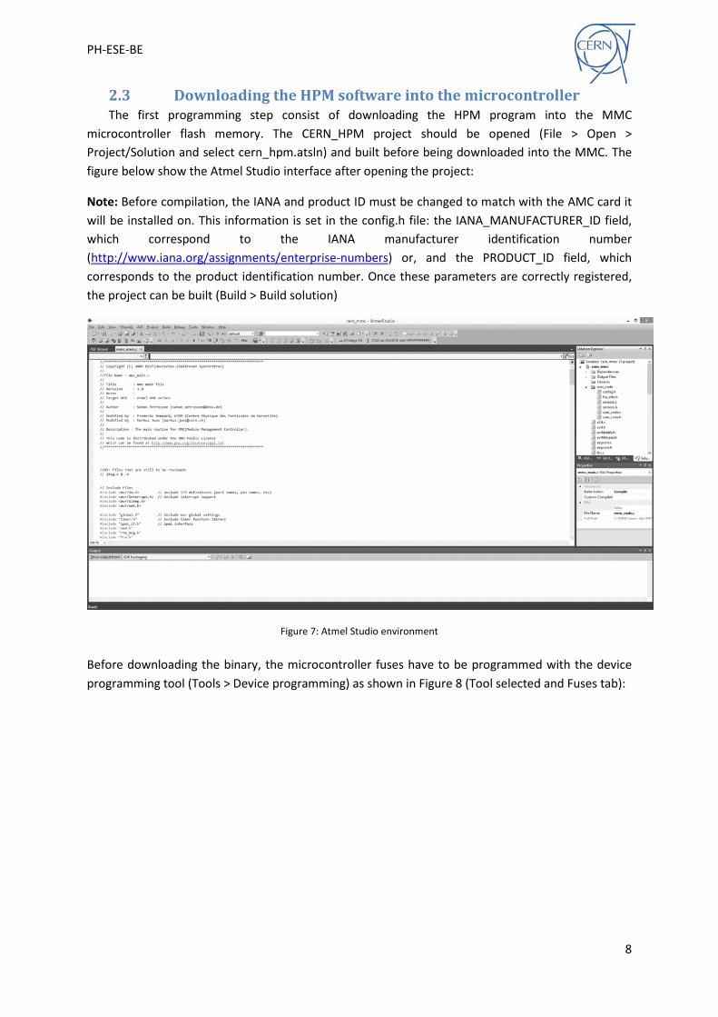
2.3 Downloading the HPM software into the microcontroller The first programming step consist of downloading the HPM program into the MMC
microcontroller flash memory. The CERN_HPM project should be opened (File > Open > Project/Solution and select cern_hpm.atsln) and built before being downloaded into the MMC. The figure below show the Atmel Studio interface after opening the project:
Note: Before compilation, the IANA and product ID must be changed to match with the AMC card it will be installed on. This information is set in the config.h file: the IANA_MANUFACTURER_ID field, which correspond to the IANA manufacturer identification number (http://www.iana.org/assignments/enterprise-numbers) or, and the PRODUCT_ID field, which corresponds to the product identification number. Once these parameters are correctly registered, the project can be built (Build > Build solution)
Figure 7: Atmel Studio environment
Before downloading the binary, the microcontroller fuses have to be programmed with the device programming tool (Tools > Device programming) as shown in Figure 8 (Tool selected and Fuses tab):

PH-ESE-BE
9
Figure 8: MMC microcontroller fuse configuration
Finally the HPM binary can be downloaded into the microcontroller flash memory (click the “program” button in the Flash box):
Figure 9: MMC bootloader programming using JTAG

PH-ESE-BE
10
2.4 Downloading/upgrading the MMC application (JTAG) The MMC application must first be built using Atmel Studio. The cern_mmc project must be
opened and can be adapted to fit the specific AMC requirements as detailed in section 5. The binary can be generated (Build > Build solution) from the user code template (default) and downloaded into the MMC (Tools > Device programming) as shown on Figure 10 (Important: The “Erase device before programming” box must not be checked):
Figure 10: MMC application programming via JTAG
The original user code (template) allows starting the AMC with the default FRU information and power ON/OFF sequence. This template does not implement any custom sensors.
Note: If an uRTM is used with the AMC module, the files present in the user_code directory must be replaced with those present under “user_code (with uRTM)” before compiling. The next section describes how to perform the same action without JTGA (using the HPM.1 feature).
2.5 Downloading/upgrading the MMC application (HPM.1) The MMC application can be downloaded/upgraded via HPM.1 (download performed via IPMI
commands; no JTAG programmer required) with the HPMDownloader program (included in the SVN repository). This software was originally written for Linux and can be used with Cygwin on Windows (The installation procedure is given in Appendix A).
The MMC application must first be built as described in section 2.4. The default/cern_mmc.hex file generated at compilation time will be used to program the MMC. In parallel, the HPMDownloader software must be compiled by executing the make command (using Cygwin or a Linux terminal –

PH-ESE-BE
11
libcrypto and libssl are required) from the tool directory. Finally, the MMC Application program can then be downloaded by running the “./hpmdownloader <.hex file>” command, where <.hex file> is the binary generated previously. During execution, some information is requested to create the HPM image used to check the target compatibility. Thus the importance to register the appropriate IANA and product ID numbers as explained in section 2.3 of this document. Below (Figure 11) is an example of MMC programming using the HPMDownloader software:
Figure 11: MMC programming using HPM.1

PH-ESE-BE
12
3 Hardware
3.1 Mezzanine pinout Pin Pin name µC Description 1 12 Volts PF0 / ADC[0] 12 volts monitoring 2 GPIO[0] / FPGA nReset PC2 User / FPGA nReset IO 3 GPIO[1] / FPGA2 Init done PC4 User / FPGA2 Init done IO 4 GPIO[2] / FPGA nReload PC3 User / FPGA nReload IO 5 GPIO[3] / FPGA1 Init done PC5 User / FPGA1 Init done IO 6 Green nLED PB6 Green LED (AMC front) 7 MMC SCL PD4 Local I2C bus (SCL) 8 Blue nLED PB7 Blue LED (Mandatory, AMC front) 9 MMC SDA PD5 Local I2C bus (SDA)
10 Red nLED PB5 Red LED (AMC front) 11 Handle switch nCLOSED PD2 Handle switch input 12 GND 13 Low voltage POK PA0 Low voltage failure detection 14 IPMB-L SCL PD0 IPMB-L bus (SCL) 15 GA1 PB2 Geographical address bit 1 16 IPMB-L SDA PD1 IPMB-L bus (SDA) 17 GA0 PB1 Geographical address bit 0 18 GPIO[4] / Regulator Enable PC6 User / Regulator enable IO 19 nPS1 PE2 Present signal (PS1) 20 GPIO[5] / DCDC Enable PC7 User / DCDC enable IO 21 nPS0 PE3 Present signal (PS0) 22 GA 2 PB3 Geographical address 2 23 GPIO[13] / RTM PS PA2 User (no RTM) / RTM present signal 24 AMC nENABLE RESET AMC enable N signal 25 GPIO[14] / RTM 12 volts enable PA3 User (no RTM) / RTM 12V enable signal 26 GPIO[6] / ADC[1] PF1 / ADC[1] User IO (Optionally Analog 1) 27 GPIO[15] / RTM 3.3 volts enable PA4 User (no RTM) / RTM 3.3V enable signal 28 GPIO[7] / ADC[2] PF2 / ADC[2] User IO (Optionally Analog 2) 29 GND 30 GPIO[8] / ADC[3] PF3 / ADC[3] User / Payload / Analog signal 31 GPIO[16] / RTM I2C Enable PA5 User (no RTM) / RTM I2C enable signal 32 Master TCK PG0 Master JTAG (TCK) 33 GPIO[9] PE6 User / Payload IO 34 Master TMS PG1 Master JTGA (TMS) 35 GPIO[10] PE4 User / Payload IO 36 Master TDO PG2 Master JTAG (TDO) 37 GPIO[11] PE5 User / Payload IO 38 Local TDI PG3 Master JTAG (TDI) 39 3.3 Volts 40 GPIO[12] PE7 User / Payload IO
Table 1: MMC mezzanine pinout

PH-ESE-BE
13
4 HPM.1 HPM.1 (Hardware Platform Management .1) is a PICMG standard specifying remote firmware
upgrade features of IPM Controller (e.g.: MMC). HPM.1 support requires a boot loader program to be downloaded into the microcontroller flash memory to re-write the flash application memory. The HPM directory present in the SVN directory contains the boot loader program for the MMC microcontroller. The MMC microcontroller flash architecture is shown below (Figure 12):
Figure 12: MMC microcontroller flash memory architecture
The Application Flash Section can be erased and written by the boot loader program that contains the HPM project binary. The MMC application is stored in the application flash section. Upon startup, the microcontroller begins at the first boot loader section address with the following algorithm (Figure 13) that decides which of the HPM or MMC application should be executed:
Figure 13: Start-up algorithm

PH-ESE-BE
14
5 MMC Application software This section describes the features implemented on the CERN MMC as well as how to customize
the source code according to the specific AMC project needs and requirements.
5.1 Commands implemented The table below (Table 2) lists the IPMI commands supported by the MMC program. These
commands are specified by the IPMI 1.5 [1] and PICMG ATCA [4]/AMC.0 [2] standards. In addition, OEM commands (NetFN 2Eh) and/or controller specific commands (NetFN 30h) can optionally be implemented by user.
Name NetFN Cmd Description Get device id 06h 01h Get device information Broadcast get device id 06h 01h Idem, broadcasted to all devices Set event receiver 04h 00h Set event register IPMB address Get event receiver 04h 01h Get event register IPMB address Get device SDR info 04h 20h Get information about SDR Get device SDR 04h 21h Read SDR register(s) Reserve device SDR repo. 04h 22h Get reservation ID used to read SDR Get sensor threshold 04h 27h Get threshold for specified sensor Get sensor reading 04h 2Dh Get sensor value (raw) Get FRU inventory area info 0Ah 10h Get information about FRU Read FRU data 0Ah 11h Read FRU information byte(s) Write FRU data 0Ah 12h Write FRU information byte(s) Get properties 2Ch 00h Get device properties FRU control 2Ch 04h FRU control (reset, reboot …) Get FRU led properties 2Ch 05h Get properties of specified LED Get led colour capabilities 2Ch 06h Get colour capabilities of specified LED Set FRU led state 2Ch 07h Set LED state (ON/OFF, blink, lamp test) Get FRU led state 2Ch 08h Get state of specified LED Get device locator record 2Ch 0Dh Read device locator record Set power level 2Ch 11h Control power level Set AMC port state 2Ch 19h Enable/Disable AMC port Get AMC port state 2Ch 1Ah Get AMC port state FRU control capabilities 2Ch 1Eh Get control capabilities (reboot, reset …) Set clock state 2Ch 2Ch Foreseen Get clock state 2Ch 2Dh Foreseen
Table 2: IPMI and PICMG commands implemented
The table below (Table 3) lists the HPM commands supported by the CERN MMC.
Name NetFN Cmd Description Get target upgrade capabilities 2Ch 2Eh Get upgrade features capabilities Get component properties 2Ch 2Fh Get component information (version …) Initiate upgrade action 2Ch 30h Start an upgrade action Upload firmware block 2Ch 32h Upload firmware binary Finish firmware upload 2Ch 33h Check the binary size and finalize the upgrade Get upgrade status 2Ch 34h Get information about the ongoing upgrade
Table 3: HPM commands implemented

PH-ESE-BE
15
5.2 User code architecture The CERN MMC source code is divided into two parts: core and user. In principle, users only need
to modify the files present in the user_code directory:
Config file (config.h): o Product information (IANA, Product ID, Firmware version) o User IOs configuration o Payload sequences (Power ON/OFF, reboot, warm/cold reset) o Additional LEDs description
Fru info file (fru_info.h): o FRU information (Language, Generator source information , enabled areas) o Board information area (Board name, serial number, product number, …) o Product information area (Product name, manufacturer, serial number, …) o Point to point connectivity record (E-Keying) o Clock configuration record (Clock E-Keying) o Module current record (Current limit)
Sensors files (sensors.h and sensors.c): o Header file contains SDR descriptions (Up to 42 SDRs (40 users + 2 Generic)) o Source code file contains sensor initialisation function o Source code file contains sensor monitoring function (polled every 100ms)
User code files (user_code.c): o OEM commands o Controller specific commands o User main function for bench top use
E-Keying management file (ekeying.c): o AMC port initialization o User command for activation/de-activation of AMC port o User command for activation/de-activation of AMC clock
5.3 User GPIO Some microcontroller pins can optionally be used as user defined GPIO. In addition, a few generic
pins can have multiple usages as described in section 3.2. The default configuration of these pins corresponds to their main function (E.g.: default configuration of pin PC2 is output as required by the FPGA nReset signal). In any case, all GPIO compatible pins are freely configurable as shown below:
user_code/config.h:
/** USER GPIO INITIALIZATION */ //#define GPIO0_DIR INPUT //Not defined -> FPGA nRESET config. //#define GPIO1_DIR INPUT //Not defined -> FPGA2 Init done config. //#define GPIO2_DIR INPUT //Not defined -> FPGA nReload config. //#define GPIO3_DIR INPUT //Not defined -> FPGA1 Init done config. //#define GPIO4_DIR INPUT //Not defined -> Regulator Enable config. //#define GPIO5_DIR INPUT //Not defined -> DCDC Enable config. #define GPIO6_DIR OUTPUT #define GPIO7_DIR OUTPUT #define GPIO8_DIR OUTPUT #define GPIO9_DIR OUTPUT #define GPIO10_DIR OUTPUT #define GPIO11_DIR OUTPUT #define GPIO12_DIR OUTPUT

PH-ESE-BE
16
5.4 Analog to Digital Converter (ADC) Some microcontroller pins can optionally be used as analogue inputs. By default, these pins are configured as GPIO but can be redefined with the ENABLE_ADC<n> macro (<n> is the identifier of the ADC to be enabled). This configuration overwrites previous GPIO configuration for the dedicated pin. The example below shows how to enable ADC features for pin PF1 and PF2:
/** USER ADC INITIALIZATION */ #define ENABLE_ADC1 //ADC[1] is associated with the PF1 pin. #define ENABLE_ADC2 //ADC[2] is associated with the PF2 pin. //#define ENABLE_ADC3 //ADC[3] is associated with the PF3 pin. //#define ENABLE_ADC4 //ADC[4] is associated with the PF4 pin. //#define ENABLE_ADC5 //ADC[5] is associated with the PF5 pin. //#define ENABLE_ADC6 //ADC[6] is associated with the PF6 pin. //#define ENABLE_ADC7 //ADC[7] is associated with the PF7 pin.
Note: ADC[0] is used for payload power monitoring
5.5 FRU information The FRU information is divided in 5 zones: internal use area, chassis info area, board area, product
info area and multi-record area. It is important to note that only the last three sections are used by the MMC software. All information required to generate the FRU information binary is defined in the user_code/fru_info.h file. The list below describes the fields of the different sections:
Board area info: Contains the following information about the board o BOARD_MANUFACTURER: Manufacturer name (E.g.: “CERN”, max. 63 characters) o BOARD_NAME: Board name (E.g.: “AMC-Board” , max. 63 characters) o BOARD_SN: Board serial number (E.g.: “AMC-000001” , max. 63 characters) o BOARD_PM: Board Product number (E.g.: “00001” , max. 63 characters)
Product information area: Contains the following information about the product o PRODUCT_MANUFACTURER: Product manufacturer name (max. 63 characters) o PRODUCT_NAME: Product name (E.g.: “MMC-Template” , max. 63 characters) o PRODUCT_PN: Product part number (E.g.: “0000” , max. 63 characters) o PRODUCT_VERSION: Product version (E.g.: “v1.0” , max. 63 characters) o PRODUCT_SN: Product serial number (E.g.: “sn:00000001” , max. 63 characters) o PRODUCT_ASSET_TAG: Product asset tag (E.g.: “”, max. 63 characters)
MultiRecord area: Contains the following records o AMC point to point connectivity record (Optional) o AMC clock configuration record (Optional - foreseen) o Module current record (Mandatory)
The AMC point to point connectivity record is defined as shown below:
#define AMC_POINT_TO_POINT_RECORD_LIST \ <p2p_definition> \ <p2p_definition> \ …
#define AMC_POINT_TO_POINT_RECORD_CNT <number_of_p2p_definition>
Note: Only one <p2p_definition> must be set by port (only one ID by port).

PH-ESE-BE
17
Where <p2p_definition> should be one of the two macros described below:
GENERIC_POINT_TO_POINT_RECORD(id, amc_port, protocol, ext, matching) o Id : Should be from 0 to AMC_POINT_TO_POINT_RECORD_CNT and unique o Port: PORT(n) where n is the AMC port number (from 0 to 11) o Protocol and ext:
For protocol PCIE, extension could be: • GEN1_NO_SSC • GEN1_SSC • GEN2_NO_SSC • GEN2_SSC
For protocol PCIE_ADV_SWITCHING, there is no extension (NO_EXT) For protocol ETHERNET, extension could be:
• BASE_1G_BX • BASE_10G_BX4
For protocol SERIAL_RAPID_IO, extension could be: • MBAUD_1250 (1.25 GBauds) • MBAUD_2500 (2.5 GBauds) • MBAUD_3125 (3.125 GBauds) • MBAUD_5000 (5.00 GBauds) • MBAUD_6250 (6.25 GBauds)
For protocol STORAGE, there is no extension (NO_EXT) o Matching:
EXACT_MATCHES MATCHES_01 MATCHES_10
OEM_POINT_TO_POINT_RECORD(id, port, oem_id, matching)
o Id: Should be from 0 to AMC_POINT_TO_POINT_RECORD_CNT and unique o Port: PORT(n) where n is the AMC port number (from 0 to 11) o Oem_id: identifies the custom protocol (See OEM_GUID description below) o Matching:
EXACT_MATCHES MATCHES_01 MATCHES_10
To identify an OEM connectivity, the carrier manager uses one GUID (Global Unique ID) number based on 16 bytes. The GUID format is defined in the Attachment A of the Wired for Management Baseline, Version 2.0 specification [5]. A GUID generator can be found on the web (E.g.: http://createguid.com/). The step given below shows how to register a GUID for an OEM protocol:
#define POINT_TO_POINT_OEM_GUID_CNT <number_of_guid>

PH-ESE-BE
18
#define POINT_TO_POINT_OEM_GUID_LIST \ <oem_guid (oem_id = 0)> \ <oem_guid (oem_id = 1)> \ <oem_guid (oem_id = …)>
Where <oem_guid> shall be:
OEM_GUID(guid_0_msb, g1, g2, g3, g4, g5, g6, g7, g8, g9, g10, g11, g12, g13, g14, guid_15_lsb) o guid_15_lsb to guid_0_msb are the 16 GUID bytes.
Below is an example of an AMC point to point connectivity declaration (user_code/fru_info.h):
#define POINT_TO_POINT_OEM_GUID_CNT 2 #define POINT_TO_POINT_OEM_GUID_LIST \ OEM_GUID(0x97,0x47,0x06,0xa2,0x2a,0x98,0x48,0xa9,0xbd,0x96,0x7b,0xf3,0x48,0x91,0x36,0x0f) \ OEM_GUID(0x46,0xbd,0xe8,0x5f,0x44,0xbd,0x44,0x56,0xa8,0x78,0x9f,0x4a,0x7b,0x03,0xfa,0x71) #define AMC_POINT_TO_POINT_RECORD_CNT 5 #define AMC_POINT_TO_POINT_RECORD_LIST \ GENERIC_POINT_TO_POINT_RECORD(0, PORT(0), ETHERNET, BASE_1G_BX, EXACT_MATCHES) \ OEM_POINT_TO_POINT_RECORD(1, PORT(4), 0, EXACT_MATCHES) \ GENERIC_POINT_TO_POINT_RECORD(2, PORT(5), PCIE, GEN1_NO_SSC, MATCHES_10) \ OEM_POINT_TO_POINT_RECORD(1, PORT(6), 1, EXACT_MATCHES) \ GENERIC_POINT_TO_POINT_RECORD(4, PORT(7), PCIE, GEN1_NO_SSC, MATCHES_10)
5.6 SDR repository The SDR (Sensor Data Record) information describes the sensors monitored by the MMC. Different
record types exist and are described in the IPMI v1.5 standard. This document introduces only the two most frequently used types: Full sensors (E.g.: Temperature, voltage, current …) and Compact sensors (E.g.: flags …).
The sensors descriptions are present in user_code/sensors.h. Each SDR is a byte array described as follows (a commented example for a temperature sensor is available in the header file):
#define AMC<id>_RECORD { \ SDR_byte[0], \ SDR_byte[1], \ …, \ SDR_byte[n], \ }
Note: Each line, except the last one, have to finish with a backslash character.
Note: Comments must be surrounded with /* and */ only.
The <id> parameter is an identifier used for record generation and must be an integer from 0 to 17. The MMC core is limited to 18 user sensors for this release but it could be extended (contact the MMC technical person at CERN to increase this limit).
Note: The device locator, hotswap and 12V generic SDR are implemented in the core. They must be not defined in the user code. The device locator record must be customized via the FRU_NAME macro present in the config.h file.
The table below (Table 4) describes Full Sensor records type (01h):

PH-ESE-BE
19
Byte Name Size Description 1:2 Record ID 2 Filled by a MMC core function, set to 0000h 3 SDR Version 1 SDR Version, set to 51h for this version 4 Record type 1 Full sensor, set to 01h 5 Record length 1 Filled by a MMC core function, set to 00h 6 Sensor owner ID 1 Filled by a MMC core function, set to 00h 7 Sensor owner LUN 1 Filled by a MMC core function, set to 00h 8 Sensor number 1 Unique sensor number, set by user 9 Entity ID 1 Entity ID, set to C1h for AMC
10 Entity Instance 1 Filled by a MMC core function, set to 00h 11 Sensor initialization 1 Bit 6: Init scanning (1b: Enable / 0b: Disable)
Bit 5: Init Events (1b: Enable / 0b: Disable) Bit 4: Init Thresholds (1b: Enable / 0b: Disable) Bit 3: Init hysteresis (1b: Enable / 0b: Disable) Bit 2: Init sensor type (1b: Enable / 0b: Disable) Bit 1: Set to 00h Bit 0: Set to 00h
12 Sensor capabilities 1 Set to F6h to be compliant with MMC core 13 Sensor type 1 Sensor types are listed in table 36-3, Sensor Type Code
of the IPMI v1.5 standard. E.g.: Temp. (01h), Voltage (02h), Current (03h) ….
14 Event type code 1 Event type code are listed in table 36-1, Event/Reading Type Code Range of the IPMI v1.5 standard. E.g.: Threshold events (01h)
15:16 Assertion Event Mask 2 Described in Table 37-1, Full Sensor Record of the IPMI v1.5 standard. E.g.: 7Fh to enable all assertion events
17:18 Deassertion Event Mask 2 Described in Table 37-1, Full Sensor Record of the IPMI v1.5 standard. E.g.: 7Fh to enable all deassertion events
19:20 Discrete reading Mask 2 00FFh to be compliant with the MMC 21 Sensor units 1 1 Bits [7:6]: Analog (numeric) data format
00b: unsigned 01b: 1’s complement (signed) 10b: 2’s complement (signed) 11b: Does not return analog reading Bits [5:3]: Rate unit 000b: none 001b: per uS 010b: per ms 011b: per s 100b: per minute 101b: per hour 110b: per day 111b: reserved Bits [2:1]: Modifier unit 00b: none 01b: Basic unit / Modifier Unit 10b: Basic unit * modifier unit 11b: reserved Bit 0: Percentage

PH-ESE-BE
20
0b: no 1b: yes
22 Base unit 1 Described in Table 37-14, Sensor Unit Type Codes of the IPMI v1.5 standard. E.g.: Degrees C (01h), Amps (05h), Volt (05h) …
23 Modifier unit 1 Idem, 00h if not specified 24 Linearization 1 enum (linear, ln, log10, log2, e, exp10, exp2, 1/x, sqr(x),
cube(x), sqrt(x), cube-1 (x) ) 00h: linear 70h: non-linear. 71h-7Fh: non-linear, OEM defined
25 M 1 M, LS 8 bits (Sensval = (M x Raw + B x 10Bexp) + 10Rexp) 26 M, Tolerance 1 Bits[7:6]: M, MS 2 bits
Bits[5:0]: Tolerance, unsigned in +/- ½ raw 27 B 1 B, LS 8 bit (Sensval = (M x Raw + B x 10Bexp) + 10Rexp) 28 B, Accuracy 1 Bits[7:6]: B, MS 2 bits
Bits[5:0]: Accuracy, LS 6 bits in raw 29 Accuracy, Accuracy exp 1 Bits[7:4]: Accuracy, MS 4 bits in raw
Bits[3:2]: Accuracy exp, 2 bits unsigned Bits[1:0]: Reserved, set to 00b
30 R exp, B exp 1 Bits[7:4]: R exponent, 4 bits 2’s complement signed Bits[3:0]: B exponent, 4 bits 2’s complement signed
31 Analog characteristic flags 1 Set to 07h to be compliant with the MMC core 32 Nominal reading 1 Nominal sensor value in raw 33 Normal maximum 1 Normal maximum value in raw 34 Normal minimum 1 Normal minimum value in raw 35 Sensor maximum reading 1 Max reading val (E.g.: FFh for unsigned, 7Fh for signed) 36 Sensor minimum reading 1 Min reading val (E.g.: 00h for unsigned, 80h for signed) 37 Upper Non-rec. threshold 1 Upper non-recoverable threshold value in raw 38 Upper critical threshold 1 Upper critical threshold value in raw 39 Upper non-crit. threshold 1 Upper non-critical threshold value in raw 40 Lower non-rec. threshold 1 Lower non-recoverable threshold value in raw 41 Lower critical threshold 1 Lower critical threshold value in raw 42 Lower non-crit. threshold 1 Lower non critical threshold value in raw 43 Positive going hysteresis 1 Positive going threshold hysteresis value in raw (00h: no
hysteresis) 44 Negative going-hysteresis 1 Negative going threshold hysteresis value in raw (00h:
no hysteresis) 45 Reserved 1 Set to 00h 46 Reserved 1 Set to 00h 47 OEM 1 Set to 00h 48 ID String type/length 1 Bits[7:6]: Type (E.g.: 11b for ASCII)
Bits[5:0]: ID string length in bytes 49:+N ID String bytes N Sensor ID string bytes
Table 4: Full sensor SDR data
The table below (Table 5) describes Compact Sensor records type (02h):

PH-ESE-BE
21
Byte Name Size Description 1:2 Record ID 2 Filled by a MMC core function, set to 0000h 3 SDR Version 1 SDR Version, set to 51h for this version 4 Record type 1 Full sensor, set to 01h 5 Record length 1 Filled by a MMC core function, set to 00h 6 Sensor owner ID 1 Filled by a MMC core function, set to 00h 7 Sensor owner LUN 1 Filled by a MMC core function, set to 00h 8 Sensor number 1 Unique sensor number, set by user 9 Entity ID 1 Entity ID, set to C1h for AMC
10 Entity Instance 1 Filled by a MMC core function, set to 00h 11 Sensor initialization 1 Bit 6: Init scanning (1b: Enable / 0b: Disable)
Bit 5: Init Events (1b: Enable / 0b: Disable) Bit 4: Reserved, set to 00h Bit 3: Init hysteresis (1b: Enable / 0b: Disable) Bit 2: Init sensor type (1b: Enable / 0b: Disable) Bit 1: Set to 00h Bit 0: Set to 00h
12 Sensor capabilities 1 Set to F6h to be compliant with MMC core 13 Sensor type 1 Sensor types are listed in table 36-3, Sensor Type Code
of the IPMI v1.5 standard. E.g.: Temp. (01h), Voltage (02h), Current (03h) ….
14 Event type code 1 Event type code are listed in table 36-1, Event/Reading Type Code Range of the IPMI v1.5 standard. E.g.: Threshold events (01h)
15:16 Assertion Event Mask 2 Described in Table 37-1, Full Sensor Record of the IPMI v1.5 standard. E.g.: 7Fh to enable all assertion events
17:18 Deassertion Event Mask 2 Described in Table 37-1, Full Sensor Record of the IPMI v1.5 standard. E.g.: 7Fh to enable all deassertion events
19:20 Discrete reading Mask 2 00FFh to be compliant with the MMC 21 Sensor units 1 1 Bits [7:6]: Analog (numeric) data format
00b: unsigned 01b: 1’s complement (signed) 10b: 2’s complement (signed) 11b: Does not return analog reading Bits [5:3]: Rate unit 000b: none 001b: per uS 010b: per ms 011b: per s 100b: per minute 101b: per hour 110b: per day 111b: reserved Bits [2:1]: Modifier unit 00b: none 01b: Basic unit / Modifier Unit 10b: Basic unit * modifier unit 11b: reserved Bit 0: Percentage

PH-ESE-BE
22
0b: no 1b: yes
22 Base unit 1 Described in Table 37-14, Sensor Unit Type Codes of the IPMI v1.5 standard. E.g.: Degrees C (01h), Amps (05h), Volt (05h) …
23 Modifier unit 1 Idem, 00h if not specified 24:25 Sensor Record Sharing 2 Bits[15:14]: Reserved, set to 00h
Bits[13:12]: ID String instance modifier type 00b: numeric 01b: alpha Bits[11:8]: Share count (number of sensor sharing this record). E.g.: if the starting sensor number was 10, and the share count was 3, then sensors 10, 11 and 12 would share this record. Bit[7]: Entity instance sharing. Set to 1b Bits[6:0]: ID String Instance modifier offset Multiple Discrete sensors can share the same sensor data record. The ID tring Instance Modifier and Modifier Offset are used to modify the Sensor ID tring as follows: Suppose sensor ID is “Temp ” for ‘Temperature Sensor’, share count = 3, ID string instance modifier = numeric, instance modifier offset = 5 - then the sensors could be identified as: Temp 5, Temp 6, Temp 7. If the modifier = alpha, offset=0 corresponds to ‘A’, offset=25 corresponds to ‘Z’, and offset = 26 corresponds to ‘AA’, thus, for offset=26 the sensors could be identified as: Temp AA, Temp AB, Temp AC (alpha characters are considered to be base 26 for ASCII)
26 Positive going hysteresis 1 Positive going threshold hysteresis value in raw (00h: no hysteresis). Note: Cannot use shared record if sensors require individual hysteresis settings.
27 Negative going-hysteresis 1 Negative going threshold hysteresis value in raw (00h: no hysteresis). Note: Cannot use shared record if sensors require individual hysteresis settings.
45 Reserved 1 Set to 00h 46 Reserved 1 Set to 00h 47 OEM 1 Set to 00h 48 ID String type/length 1 Bits[7:6]: Type (E.g.: 11b for ASCII)
Bits[5:0]: ID string length in bytes 49:+N ID String bytes N Sensor ID string bytes
Table 5: Compact sensor SDR data

PH-ESE-BE
23
5.7 Power management The power management (DC/DC control, Regulators enabling, etc) of an AMC must be taken care
of by the MMC. The standard defines a few sequences to be executed: power ON sequence (Mandatory), power OFF sequence (Mandatory), reboot (Optional), warm reset (Optional) or cold reset (Optional). These sequences are user defined (depend on the AMC requirements).
The sequences configuration is described below (user_code/config.h):
#define POWER_ON_SEQ \ <action> \ …
#define POWER_OFF_SEQ \ <action> \ …
#define REBOOT_SEQ \ <action> \ …
#define WARM_RESET_SEQ \ <action> \ …
#define COLD_RESET_SET \ <action> \ …
Note: To disable optional sequences, the related define must be removed or commented out.
Note: Each line, except the last one, have to finish with a backslash character.
Note: Comments must be surrounded with /* and */ only.
The <action> parameter must be one of the macros described below:
SET_PAYLOAD_SIGNAL(<signal>) o <signal>: name of the pin’s signal (Appendix A)
CLEAR_PAYLOAD_SIGNAL(<signal>) o <signal>: name of the pin’s signal (Appendix A)
WAIT_FOR_HIGH(<signal>,<timeout >,<error>) o <signal>: name of the pin’s signal (Appendix A) o <timeout>: timeout in ms o <error>: could be C code (executed in if statement) or one of the following macros
PON_ERROR: Send a power ON failure event to the MCH and then, execute POWER_OFF_SEQ.
PON_CONTINUE: Continue the in progress sequence POFF_ERROR: Stop the sequence

PH-ESE-BE
24
WAIT_FOR_LOW(<signal>,<timeout >,<error>) o <signal>: name of the pin’s signal (Appendix A) o <timeout>: timeout in ms o <error>: could be C code (executed in if statement) or one of the following macros
PON_ERROR: Send a power ON failure event to the MCH and then, execute POWER_OFF_SEQ.
PON_CONTINUE: Continue the in progress sequence POFF_ERROR: Stop the sequence
SET_REGISTER(<reg_name>,<value>) o <reg_name>: register name (e.g.: DDRx, PORTx …)
<value>: value to set in the register DELAY(<delay >)
o <delay>: delay in ms CUSTOM_C(<c_code>)
o <c_code>: user’s C code to perform custom action (configure I2C component …)
Below is an example of the power ON sequence:
#define POWER_ON_SEQ \ SET_PAYLOAD_SIGNAL(LOCAL_DCDC_ENABLE) /* Set LOCAL_DCDC_ENABLE signal to high */ \ SET_PAYLOAD_SIGNAL(LOCAL_REG_ENABLE) /* Set LOCAL_REG_ENABLE signal to high */ \ WAIT_FOR_LOW(LOCAL_FPGA1_INIT_DONE, 500, PON_ERROR) /* Wait for LOCAL_FPGA1_INIT_DONE */ \ SET_REGISTER(DDRA, (DDRA & 0x0F) | 0x04) /* Set DDRA register */ \ CUSTOM_C( /* Execute custom c code */ \ /* Put your C code here (below is an example) */ \ int myvar = 0; \ for(myvar =0; myvar < 5; myvar ++) \ PORTA = get_ipmi_address()+myvar; \ ) \ DELAY(500) /* Delay of 500 ms */ \ CLEAR_PAYLOAD_SIGNAL(GPIO_1) /* Set GPIO_1 signal to low */
5.8 E-keying The e-keying specification, included in the AMC.0 standard [2], describes an automatic feature to
check port compatibility between modules installed on a common backplane. The AMC ports must be defined in the FRU information (section 5.5). This information, complemented with the backplane information, is used to check the compatibility during the AMC initialization phase. Upon AMC board insertion and when the payload power is enabled, the carrier manager sends the “set AMC Port State (Enable)” command to enable all compatible AMC ports. Similarly, during the extraction procedure, the AMC ports are disabled with the “set AMC port State (Disable)” command that is sent before the payload power is disabled. The three user functions defined below (user_code/ekeying.c) are used to perform initialization, enabling and disabling actions:
void ekeying_init() o By default, all AMC ports are defined as disabled. Users can modify it by calling the
following function: set_channel_init(<desc_id>, <state>). <desc_id>: defines the port specified. The port is selected by the associated
ID defined in the point to point record of the FRU information (section 5.5). <state>: Define the initialization state and can be:
• PORT_ACTIVE • PORT_INACTIVE

PH-ESE-BE
25
u08 port_ekeying_enable(u08 id)
o This function is called when the “set AMC port state (Enable)” command is received from the carrier manager. In this function, the user can configure devices (E.g.: enable interface, configure switch …) with C functions. The macros defined in section 5.10 can also be used.
o Id: defines the specified port. The port is selected by the associated ID defined in the point to point record of the FRU information (section 5.5).
o Returned value: SUCCES FAILED NI (Not Implemented, inform that this port cannot be controlled)
u08 port_ekeying_enable(u08 id)
o This function is called when the “set AMC port state (disabled)” command is received from the carrier manager. In this function, the user can configure devices (E.g.: disable interface, remove switch configuration …) with C functions. The macros defined in section 5.10 can also be used.
o Id: defines the specified port. The port is selected by the associated ID defined in the point to point record of the FRU information (section 5.5).
o Returned value: SUCCES FAILED NI (Not Implemented, inform that this port cannot be controlled)
5.9 Sensors Two functions are dedicated to the user’s sensors. One for initialization and one for monitoring.
These functions are implemented in the user_code/sensors.c file with the following prototypes: void sensor_init_user() and void sensor_monitoring_user().
How to send/get information to/from an I2C based sensor:
GET_I2C_VAL(<address>,<sub_addr>,<sub_addr_type>,<len>,<buf>) o <address>: I2C address of the device o <sub_addr>: Sub-address / register address o <sub_addr_type>: length of the sub-address
ZERO_LEN: no sub-address BYTE_LEN: 1 sub-address byte SHORT_LEN: 2 sub-address byte
o <len>: number of byte to be read o <buf>: pointer to unsigned char (u08) array where the read byte should be stocked

PH-ESE-BE
26
SEND_I2C_VAL(<address>,<sub_addr>,<sub_addr_type>,<len>,<buf>) o <address>: I2C address of the device o <sub_addr>: Sub-address / register address o <sub_addr_type>: length of the sub-address
ZERO_LEN: no sub-address BYTE_LEN: 1 sub-address byte SHORT_LEN: 2 sub-address byte
o <len>: number of byte to be sent o <buf>: pointer to unsigned char (u08) array containing bytes to be sent
How to read an analogue value from a microcontroller ADC pin:
GET_ADC(<chID>) o <chID>: ADC channel ID to be read o Returned value: unsigned char (u08) – value read by the ADC
How to set/clear a MMC microcontroller GPIO pin:
SET_SIGNAL(<signal>) o <signal>: name of the pin’s signal (Appendix B)
CLEAR_SIGNAL(<signal>) o <signal>: name of the pin’s signal (Appendix B)
How to register the sensor value:
set_sensor_value(<sensor_number>,<value>) o <sensor_number>: sensor number specified in the SDR o <value>: unsigned char (u08) value
5.10 Custom LEDs The PICMG standard defines functions to control and monitor LEDs. Three LEDs are described in
the specification: the blue led (mandatory), green led (optional – implemented) and red led (optional – implemented). Moreover, custom LEDs can be defined and controlled with the same functions or by the MMC application itself. The LEDs are implemented as described below:
#define AMC_USER_LED_LIST { \ <led array (ledID = 3)>, \ <led array (ledID = 4)>, \ … \ <led array (ledID = n)> \ }
Note: the ledID is automatically incremented and starts from 3.
Note: Each line, except the last one, have to finish with a backslash character and comments must be surrounded with /* and */ only.

PH-ESE-BE
27
Where <led array> can be one of the two arrays described below (depending on the way the LED is controlled):
LED controlled through IO Extender (PCF8574 family):
{ \ io_type: IO_EXTENDER_PCF8574AT, \ addr: <i2c_address> \ pin: <pin number> \ colour: <colour> \ init: <init_state> \ active: <pin_state> \ inactive: <pin_state> \
},
o <i2c_address>: I2C address of the IO extender o <pin number>: Pin of the IO extender (from 1 to 8) o <colour>: LED colour, can be one of the following value
BLUE RED GREEN AMBER ORANGE WHITE
o <init_state>: Initialization state of the LED, can be one of the following value ACTIVE (led ON) INACTIVE (led OFF)
o <pin_state>: pin value for active/inactive state, can be one of the following value LOW HIGH
LED controlled by a MMC microcontroller pin:
{ \ io_type: MMC_PORT, \ port: <port> \ pin: <pin> \ colour: <colour> \ init: <init_state> \ active: <pin_state> \ inactive: <pin_state> \
},
o <port>: pin’s port must be set as follow: PORT(<signal>) <signal>: name of the pin’s signal (Appendix B)
o <pin>: MMC pin, set as follow: PIN(<signal>) <signal>: name of the pin’s signal (Appendix B)

PH-ESE-BE
28
5.11 OEM commands The OEM commands defined by the IPMI v1.5 standard [1] are user defined IPMI commands.
These can be executed with the netFN 2Eh. To enable this feature, the ENABLE_OEM macro must be set in the user_code/config.h file and the ipmi_oem_user function must be implemented in the user_code/user_code.c file.
Enable oem command (user_code/config.h):
#define ENABLE_OEM
ipmi_oem_user function:
u08 ipmi_oem_user(u08 cmd , u08 *iana, u08 * data, u08 data_len, u08 *buf, u08 *error)
<cmd>: command received <iana>: 3 bytes array containing the IANA identifier (must be checked) <data>: data received <data_len>: number of received data bytes <buf>: bytes array pointer to set data to be sent (3 first bytes must be the IANA) <error>: IPMI completion code value (see Appendix C) Returned value: Number of bytes to be sent (response)
Below is an example of the implementation of the following OEM command:
Command: 01h IANA: 000060h Cmd data length: 1 byte Cmd data: data[0] = <eg0> Returned data: data[0] = <eg0>
u08 ipmi_oem_user(u08 cmd, u08 *iana, u08 * data, u08 data_len, u08 *buf, u08 *err){
//Note: You must not return more than "MAX_BYTES_READ" bytes u08 res_data_len = 0; *err = IPMI_CC_OK; if (iana[0] != 0x00 || iana[1] != 0x00 || iana[2] != 0x60){ *error = IPMI_CC_PARAM_OUT_OF_RANGE; return 0; //Wrond IANA code } buf[0] = buf[1] = 0x00; //IANA ID must be returned as the first 3 bytes buf[2] = 0x60; switch(command){ case 0x01: if(data_size == 1){ buf[3] = user_data[0]; res_data_len = 4; }else{ *err = IPMI_CC_PARAM_OUT_OF_RANGE; return 0; } break;

PH-ESE-BE
29
default: *err = IPMI_CC_PARAM_OUT_OF_RANGE;
return 0; } return res_data_len; }
5.12 Controller specific commands The controller specific commands are defined in the IPMI v1.5 standard [1]. These can be executed
with the netFN 30h. To enable this feature, the ENABLE_CONTROLLER_SPECIFIC macro must be set in the user_code/config.h file and the ipmi_controller_spec function must be implemented in the user_code/user_code.c file.
Enable controller specific command (user_code/config.h):
#define ENABLE_CONTROLLER_SPECIFIC
ipmi_oem_spec function:
u08 ipmi_controller_spec(u08 cmd , u08 * data, u08 data_len, u08 *buf, u08 *err)
<cmd>: command received <data>: data received <data_len>: number of received data bytes <buf>: bytes array pointer to set data to be sent (3 first bytes must be the IANA) <err>: IPMI completion code value (see Appendix C) Returned value: Number of bytes to be sent (response)
Below is an example of the implementation of the following controller specific command:
Command: 01h Cmd data length: 1 byte Cmd data: data[0] = <eg0> Returned data: data[0] = <eg0>
u08 ipmi_controller_specific(u08 cmd, u08 *data, u08 data_len, u08 *buf, u08 *err){
u08 rsp_length = 0; *error = IPMI_CC_OK; switch(command){ case 0x01: buf[0] = data[0]; rsp_length = 1; break;
default: *error = IPMI_CC_INV_CMD; } return rsp_length; }

PH-ESE-BE
30
5.13 Bench top A custom geographical addresses can be defined to power the AMC card in bench top use (outside
of an xTCA shelf). These addresses must be outside of the PICMG specification range and can be defined in the user_code/config.h file as follow:
#define CUSTOM_ADDR_LIST \ ADDR(<addr>,<gaddr_0>,<gaddr_1>,<gaddr_2>) \ …
Where:
<addr>: custom address, should be out of PICMG specification (E.g.: FFh) <gaddr_0>: value for GA0 pin associated to this address
o POWERED: Bit is set o GROUNDED: bit is cleared o UNCONNECTED: bit is unconnected
<gaddr_1>: value for GA1 pin associated to this address (same as above) <gaddr_2>: value for GA2 pin associated to this address (same as above)
If custom addresses are used, the user_main function should be implemented in the user_code/user_code.c file as follow:
u08 user_main(u08 addr){ /* user code */ } o addr: address detected o Returned value:
0: To continue the MMC core program when exit Others: To stop the MMC core program when exit
This function is executed if one of the user’s defined address is detected during the MMC initialization. Below is an example of a user_main function that execute POWER_ON_SEQ when the handle switch is asserted and POWER_OFF_SEQ when it is de-asserted:
u08 user_main(u08 addr){ while(1) manage_payload(); return 1; }
Moreover, sensors can be monitored with the function sensor_monitoring_user() defined in user_code/sensors.c. The sensor values can be read with:
get_sensor_value(u08 sensID) o sensID: sensor number defined in SDR o Returned value: raw sensor value

PH-ESE-BE
31
6 Appendix A: Cygwin installation on Windows Cygwin is a Unix-like command line interface for Windows. It can be downloaded from the project website (https://cygwin.com/install.html). During the installation process, the following packet must be selected to use the MMC related tools:
Make GCC LibSSL
Make:

PH-ESE-BE
32
Gcc:
LibSSL:

PH-ESE-BE
33
7 Appendix B: MMC microcontroller signals
Pin Signal name PA0 LOCAL_LOW_VOLTAGE_POK PA2 RTM_PS or GPIO_13 PA3 RTM_12V_ENABLE or GPIO_14 PA4 RTM_3V3_ENABLE or GPIO_15 PA5 RTM_I2C_ENABLE or GPIO_16 PB0 GA_PULLUP PB1 GA2 PB2 GA1 PB3 GA0 PB5 LOCAL_RED_LED PB6 LOCAL_GREEN_LED PB7 LOCAL_BLUE_LED PC2 LOCAL_RESET_FPGA or GPIO_0 PC3 LOCAL_RELOAD_FPGA or GPIO_2 PC4 LOCAL_FPGA2_INIT_DONE or GPIO_1 PC5 LOCAL_FPGA1_INIT_DONE or GPIO_3 PC6 LOCAL_REG_ENABLE or GPIO_4 PC7 LOCAL_DCDC_ENABLE or GPIO_5 PD0 IPMB_SCL PD1 IPMB_SDA PD2 LOCAL_HANDLE_SWITCH PD4 LOCAL_I2C_SCL PD5 LOCAL_I2C_SDA PE2 PS1 PE3 PS0 PE4 GPIO_10 PE5 GPIO_11 PE6 GPIO_9 PE7 GPIO_12 PF0 PRESENCE_12V PF1 GPIO_6 PF2 GPIO_7 PF3 GPIO_8 PG0 MASTER_TCK PG1 MASTER_TMS PG2 MASTER_TDO PG3 MASTER_TDI

PH-ESE-BE
34
8 References
[1] Intel, "Intelligent Platform Management Interface v1.5," Intel, 20 February 2010. [Online]. http://www.intel.com/content/dam/www/public/us/en/documents/product-briefs/spec-license-agreement.pdf
[2] PICMG, "AMC.0 standard," [Online]. https://www.picmg.org/openstandards/advanced-mezzanine-card/
[3] PICMG, "HPM.1 standard," [Online]. https://www.picmg.org/openstandards/hardware-platform-management/
[4] PICMG, "ATCA standard," [Online]. https://www.picmg.org/openstandards/advancedtca/
[5] Intel, "Wired for Management Baseline, Version 2.0," [Online]. http://download.intel.com/design/archives/wfm/downloads/base20.pdf
[6] PICMG, "MicroTCA standard," [Online]. https://www.picmg.org/openstandards/microtca/

PH-ESE-BE
35
9 Table of figures
Figure 1: ATCA Hardware Platform Management .................................................................................. 3 Figure 2: MicroTCA Hardware Platform Management ........................................................................... 4 Figure 3: Activation / De-activation state machine ................................................................................ 5 Figure 4: SVN repository architecture..................................................................................................... 6 Figure 5: USB driver installation.............................................................................................................. 7 Figure 6: Atmel Studio installation .......................................................................................................... 7 Figure 7: Atmel Studio environment ....................................................................................................... 8 Figure 8: MMC microcontroller fuse configuration ................................................................................ 9 Figure 9: MMC bootloader programming using JTAG ............................................................................ 9 Figure 10: MMC application programming via JTAG ............................................................................ 10 Figure 11: MMC programming using HPM.1 ........................................................................................ 11 Figure 12: MMC microcontroller flash memory architecture ............................................................... 13 Figure 13: Start-up algorithm ................................................................................................................ 13
10 Table of tables
Table 1: MMC mezzanine pinout .......................................................................................................... 12 Table 2: IPMI and PICMG commands implemented ............................................................................. 14 Table 3: HPM commands implemented ............................................................................................... 14 Table 4: Full sensor SDR data ................................................................................................................ 20 Table 5: Compact sensor SDR data ....................................................................................................... 22