cermax portable hygrometer
TRANSCRIPT

KAHN INSTRUMENTS, INC.
Issue October 2001
885 Wells Road, Wethersfield, CT 06109 Tel: 860-529-8643; Fax: 860-529-1895
E-mail: [email protected]
CERMAX
PORTABLE HYGROMETER
INSTALLATION, OPERATION AND MAINTENANCE MANUAL

KAHN INSTRUMENTS, INC.
Page 2
885 Wells Road, Wethersfield, CT 06109 Tel: 860-529-8643; Fax: 860-529-1895
E-mail: [email protected]
TABLE OF CONTENTS SECTION PAGE
1. INTRODUCTION 5
1.1 General 5
1.2 Calibration 5
1.3 Manufacturing Quality 5
2. OPERATING THE CERMAX INSTRUMENT 6
2.1 General 6
2.2 Basic Operation 6 2.2.1 Connecting to a Sample gas 6 2.2.2 Making a Measurement 7
2.3 Modes of Operation 7
2.4 Location of Inputs and Outputs 8 2.4.1 Battery Pack 8 2.4.2 Digital Communication Port 8 2.4.3 Auxiliary Process Variable Input 9
3. CONFIGURING CERMAX 10
3.1 User Set-up 10
3.2 The Main Screen 10
3.3 User Menus 12
3.4 Moving Around the Menus 12 3.4.1 The Main Menu 12 3.4.2 Selecting Measurement Required 13 3.4.3 Selecting Dewpoint options 13 3.4.4 Selecting PPM(W) Options 14 3.4.5 Selecting PPM(V), g/m3, lb/mmscf and %RH 14
3.5 The Auxiliary Menu 14 3.5.1 Selecting an Auxiliary Option 15 3.5.2 Selecting Set Temp/Ext Temp Temperature Unit 16 3.5.3 Entering a Set Temperature 16 3.5.4 Selecting External Temperature Transducer 17 3.5.5 Selecting a Temperature Transducer Input Range 17

KAHN INSTRUMENTS, INC.
Page 3
885 Wells Road, Wethersfield, CT 06109 Tel: 860-529-8643; Fax: 860-529-1895
E-mail: [email protected]
3.5.6 Selecting the Set Press./Ext. Press. Pressure Unit 18 3.5.7 Entering a Set Pressure Value 18 3.5.8 Entering an External Pressure Measurement Span 20 3.5.9 Selecting a Pressure Transducer Input Range 21 3.5.10 Selecting Sensor Options 21 3.5.11 Selecting Display Options 22
3.6 The Logging Menu 23 3.6.1 Starting a Logging Session 23 3.6.2 Entering a Text Identifier 23 3.6.3 Setting the Sample Interval 24 3.6.4 Entering the Number of Samples Required 24 3.6.5 Starting a Logging Session 25 3.6.6 Immediate Start 25 3.6.7 Delayed Start 26 3.6.8 Stopping a Logging Session 26 3.6.9 Selecting a Previously Logged Session to View 27 3.6.10 Logging Display 27 3.6.11 Viewing Logged Samples 28 3.6.12 Downloading Logged Data from CERMAX to PC MS Excel 29
3.7 Serial Communication 30 3.7.1 Using Terminal Commands 31 3.7.2 Downloading Logged Data 32
3.8 Charging 33
4. MECHANICAL INSTALLATION 34
4.1 General 34
4.2 Sampling Hints 34
4.3 Response Characteristics 35
4.4 Which Gases to Measure 36
5. MAINTENANCE 37
5.1 General 37
5.2 CERMAX Sensor Assembly Removal and Replacement. 37 5.2.1 Sensor Assembly Removal 38 5.2.2 Sensor Assembly Replacement 38
6. TECHNICAL SPECIFICATIONS 41

KAHN INSTRUMENTS, INC.
Page 4
885 Wells Road, Wethersfield, CT 06109 Tel: 860-529-8643; Fax: 860-529-1895
E-mail: [email protected]
FIGURES PAGE Figure 1. Opening Screen 10 Figure 2. Main Screen 11 Figure 3. Main Screen, with Low Power Indication 11 Figure 4. Logged Data Screen 11 Figure 5. Main Menu 13 Figure 6. Selecting Dewpoint Measurement 13 Figure 7. Selecting Dewpoint Temperature Unit 13 Figure 8. Selecting Dewpoint Over Water Measurement 14 Figure 9. Selecting PPM(W) Gas Option 14 Figure 10. Auxiliary Menu 15 Figure 11. Selecting an Auxiliary Option 16 Figure 12. Selecting the Set Temp/Ext Temp Temperature Unit 16 Figure 13. Entering a Set Temperature 17 Figure 14. Selecting the Temperature Transducer 17 Figure 15. Selecting the Input Zero Condition 18 Figure 16. Selecting the Set Press./Ext. Press. Pressure Unit 18 Figure 17. Entering a Set Pressure Value 19 Figure 18. Entering an External Pressure Measurement Span 20 Figure 19. Selecting a Pressure Transducer Input Range 21 Figure 20. Selecting Sensor Options 21 Figure 21. Selecting Display Options 22 Figure 22. Auxiliary Display Showing Pressure Compensated Dewpoint 22 Figure 23. Auxiliary Display Showing Input Pressure 23 Figure 24. Logging Menu 23 Figure 25. Entering a Text Identifier 24 Figure 26. Setting the Sample Interval 24 Figure 27. Entering the Number of Samples 25 Figure 28. Start Logging Immediately 25 Figure 29. Selecting Delayed Start Logging 26 Figure 30. Stopping a Logging Session 26 Figure 31. Selecting a Previously Logged Session to View 27 Figure 32. Logging Display with No Data 27 Figure 33. Logged Data 28 Figure 34. Selecting a Sample to View 29 Figure 35. Viewing a Selected Sample 29 Figure 36. CERMAX - Showing Sensor Replacement 40 APPENDIX Appendix 1. RECOMMENDED SAMPLING SYSTEM 42

KAHN INSTRUMENTS, INC.
Page 5
885 Wells Road, Wethersfield, CT 06109 Tel: 860-529-8643; Fax: 860-529-1895
E-mail: [email protected]
1. INTRODUCTION
1.1 General CERMAX is an advanced portable instrument for the measurement of absolute moisture content of air or other gases. It is designed to fulfill a wide range of applications by direct read out of moisture content displayed on the LCD display. The instrument offers several customer selectable display options based on a calibrated dewpoint measurement range of -100 to +20°C. The instrument provides indication only from -100 to -120°C dewpoint.
1.2 Calibration Calibration is performed using precision dewpoint generators and transfer standard optical hygrometers which have been calibrated directly at the National Institute of Standards and Technology (NIST). As with all precision measurement equipment, calibration integrity depends on regular verification. Kahn Instruments suggest that the instrument be returned to the Kahn Calibration Laboratory at least once a year for a re-calibration. Alternatively an exchange sensor can be ordered and simply installed by the user on-site to avoid costly downtime. In either case, calibration is inexpensive and ensures continued accurate operation of the instrument.
1.3 Manufacturing Quality Your hygrometer should reach you in perfect working condition. Rigorous procedures at every stage of production ensure that the materials of construction, manufacturing, calibration and final test procedures meet the requirements laid down by our Quality System.

KAHN INSTRUMENTS, INC.
Page 6
885 Wells Road, Wethersfield, CT 06109 Tel: 860-529-8643; Fax: 860-529-1895
E-mail: [email protected]
2. Operating the Cermax Instrument
2.1 General Operation of CERMAX is very simple as long as necessary precautions are taken to protect the sensor from damage. Statistical information indicates that the vast majority of failures are caused either by incorrect sampling methods, sampling positions or inadequate protection against harmful substances.
2.2 Basic Operation A brief summary of the operating procedure of CERMAX is shown on the instruction label which is attached to the inside of the instrument case flap. This instruction label is designed to remind the user, through the use of simple graphical representations, of the key methods of connecting to the instrument for gas sampling, communication, remote process variable input and battery charging. Each aspect is explained in a step-by-step sequence identifying the stages required to achieve the quickest route to the desired outcome. The flap label has two sections, each presented as a horizontal row. The first row, at the top of the label, identifies the steps needed to connect the instrument to the gas under test, perform a measurement and access the instrument configuration menus. The bottom row shows the location of the communications port, the external charging socket, the auxiliary process variable inputs and the battery pack.
2.2.1 Connecting to a Sample gas Care should be taken to ensure that the gas connected to the Cermax instrument, and any tubing used to make the connection, contains NO LIQUIDS in droplet form and NO PARTICULATE matter. Refer to section 4.2 of this manual for further information and sampling hints. The gas connections to the Cermax are made by way of the two Swagelok type S.S. bulkhead fittings that take 1/8” o.d. sample pipe. The bulkheads are identified as inlet and outlet by the symbols molded into the case. Care should be taken to follow the polarity of connection suggested. Gas under test should be restricted to flow rates between 1 and 5 normal liters per minute and pressures from atmospheric to 6000 PSIG. When connecting the sample tubing, ensure that the components are finger-tight and then tightened a further 90° using a suitable wrench. Care should be taken not to over-tighten the bulkhead fittings as this may result in damage to the instrument.

KAHN INSTRUMENTS, INC.
Page 7
885 Wells Road, Wethersfield, CT 06109 Tel: 860-529-8643; Fax: 860-529-1895
E-mail: [email protected]
2.2.2 Making a Measurement After connecting the sample gas, the instrument should be turned on using the on/off switch located on the control panel. Select the required user setup mode: Default to use standard configuration settings; Previous to re-use custom settings from the last measurement cycle. After a short initialization period, a reading of the sample gas moisture determination will be displayed. Changes to the display configuration can now be made. Details of the display options, and their methods of selection, can be found in section 3, Configuring Cermax.
2.3 Modes of Operation The CERMAX instrument has two basic modes of operation, Field Mode and Laboratory Mode. For details on the method of selection for Field Mode and Lab Mode, see sections 3.7 Serial Communication and 3.7.1 Using Terminal Commands. Alternatively, Field and Laboratory Mode can be set from the keypad as described below. When the display shows USER SETUP: DEFAULT or PREVIOUS, pressing the “0” button will toggle the FIELD MODE or LAB MODE setting (depending upon its previous setting). When the “0” button is pressed, the new mode setting will be shown in the bottom left corner of the display. Field Mode is the default setting for normal use. In this configuration, the instrument response is optimized to the primary requirements of users of portable dewpoint hygrometers and will provide the operator with accurate dewpoint determinations in the quickest time possible. In this mode of operation, readings are typically obtained to within 2°C dp (or equivalent) of final value within 15 minutes from connecting the gas sample line to the instrument and switching it on. As a general rule, measurements of less than 2 hours continuous duration should be made in Field Mode. It is not generally recommended that measurements where the expected final reading is below -80°C dp, or equivalent, are made in Field Mode as determinations of such trace moisture levels require extended periods to reach equilibrium and are more suited to Lab Mode. Lab Mode is provided for the user who wishes to make extended measurements that make full use of the Cermax instrument’s combination of high accuracy and low dewpoint measurement capability. In Lab Mode, the instrument is configured to provide the ultimate in terms of accuracy but at the expense of longer stabilization times. This mode of operation is best suited to either measurements made under exacting laboratory conditions or where the instrument is to be left attached to the same gas stream for extended periods of operation. Measurements of longer than two hours should be made in Lab Mode.

KAHN INSTRUMENTS, INC.
Page 8
885 Wells Road, Wethersfield, CT 06109 Tel: 860-529-8643; Fax: 860-529-1895
E-mail: [email protected]
For clarity, the selected mode of operation is displayed continually to the user via the instrument display. The selected mode of operation is also included in the header attached to logged data files.
2.4 Location of Inputs and Outputs The Cermax instrument is a powerful measurement tool which can perform many advanced functions. In order to make full use of these functions, it is first necessary to know where the inputs and outputs are located and what their purpose is.
2.4.1 Battery Pack The Cermax battery pack is located on the opposite side of the case from the display as is shown graphically on the case flap label. The battery pack is a sub-assembly held in place by four screws and can be removed either for charging or to be exchanged in the field for a spare battery pack should a low battery warning condition occur during a measurement. The connector for charging the battery pack out of the instrument is clearly identified by a label on the battery pack itself. Alternatively, the battery pack can be charged when it is still connected to the instrument. To do this, plug the charger provided into the external charging point located behind the cover to the side of the gas connection bulkheads. This cover is held in place by two screws. Its location is also shown on the case flap label. The Cermax can be operated when using the external charging point. This method of powering the instrument may also be used where continuous measurements in excess of 24 hours are desired. Spare battery packs are available for the Cermax. Use only battery packs and charger systems supplied for use with the Cermax. Use of any other chargers or batteries will result in permanent damage to the instrument. Note: Do not connect the battery charger to any other ports on the instrument, particularly the auxiliary process variable input, as damage will result to the charger and the instrument.
2.4.2 Digital Communication Port The Cermax instrument is provided with an RS232 digital communications port. This is to allow the operator to access some of the instrument configuration parameters that are not accessible via the keypad and also to download logged data files (see sections 3.6 The Logging Menu and 3.7 Serial Communications for more information). The communications port is located alongside the external battery charging point, behind the

KAHN INSTRUMENTS, INC.
Page 9
885 Wells Road, Wethersfield, CT 06109 Tel: 860-529-8643; Fax: 860-529-1895
E-mail: [email protected]
panel to the side of the sample gas bulkheads. Connection to this port is made at the instrument by using a cable with a 9-way male D-plug termination. The cable used should be chosen to have termination at the other end that matches the requirements of your chosen terminal device. If this is to be a PC using a standard Com port, such as that used typically for a mouse, then it is recommended that a standard communication cable be used. Please contact your local Kahn Instruments representative if you have any difficulty obtaining a suitable cable.
2.4.3 Auxiliary Process Variable Input The Cermax instrument is a powerful measurement device, capable of compensating moisture determinations for the effects of temperature and pressure either automatically or by manual entry of these process variables. When operating in the automatic compensation mode, an external industry-standard transducer is used to provide the auxiliary process variable measurement. The connection of this external transducer to the Cermax is made at the rear of the instrument by way of the two 4mm banana-plug connections. This input will accept current signals in either 0-20mA or 4-20mA format (user selectable). The connectors provided are color coded and care should be taken to observe correct polarity when connecting an external process variable transducer to the Cermax. Please note that the Cermax does not provide excitation voltage for the external process variable transducer and so a 3 or 4 wire type should be used with a suitable external power supply. Please refer to section 3.5 The Auxiliary Menu for details on the configuration and use of this function. Your local Kahn Instruments representative will be pleased to advise of a suitable auxiliary process variable transducer. These are also available from Kahn Instruments as optional extras. Note: Damage to the instrument will occur if a reverse polarity connection is made or if the instrument battery charger is mistakenly connected to either of the 4mm banana plugs.

KAHN INSTRUMENTS, INC.
Page 10
885 Wells Road, Wethersfield, CT 06109 Tel: 860-529-8643; Fax: 860-529-1895
E-mail: [email protected]
3. CONFIGURING CERMAX
3.1 User Set-up On power-up, the user may choose to use the default menu options or the previously set options. Selecting the DEFAULT set-up will cause previously selected options to be lost and the following default configuration to be set:
• Main display option set to Dewpoint, Over Ice • Auxiliary option set to None • Temperature units are set to °Fahrenheit if US format has been selected, or
°Celsius if UK format has been selected. (See section 3.7 Serial Communication)
• Pressure units are set to PSIG. • Dewpoint is calculated for the sensor at atmospheric pressure. • The auxiliary display will show compensated dewpoint where applicable.
The user may subsequently change the options via the user menus. To toggle between the user setup options, press the ! key. To select an option, press the select key. The screen will change to the Main Display.
Figure 1. Opening Screen
3.2 The Main Screen The Main Screen includes both the Main Display, as defined by the Main Display Menu options, and the Auxiliary Display, as defined by the Auxiliary Display Menu options. The selected operating mode is shown in the bottom center of the screen. The bottom right of the screen displays the date when the sensor is next due for calibration. This message will be replaced by a warning if the battery power falls below the optimum value.
CERMAX SENSOR ID C123 C45 CALIBRATED 04:14:97 SOFTWARE VERSION 1.90.00 KAHN INSTRUMENTS, INC. USER SETUP: DEFAULT" PREVIOUS BATTERY CHECK OK

KAHN INSTRUMENTS, INC.
Page 11
885 Wells Road, Wethersfield, CT 06109 Tel: 860-529-8643; Fax: 860-529-1895
E-mail: [email protected]
Figure 2. Main Screen
Figure 3. Main Screen, with Low Power Indication
To toggle between the Main Screen and the Logged Data screen, press the display key. If no logged data is currently held in the logging memory, the Logging Display will show the current date and time. If not correct, change the date and/or time using the terminal commands (see section on Communication)
Figure 4. Logged Data Screen
Pressure at Atmosphere
-15.4°C DP
WARNING - LOW BATTERY
DATE 04:14:97 TIME 14:25 NO LOGGED DATA AVAILABLE
Pressure at Atmosphere
-15.4°C DP
FIELD MODE CAL DUE 04:98
Auxiliary Display
Main Display
Main Option
Operating Mode
KAHN INSTRUMENTS, INC.
Page 12
885 Wells Road, Wethersfield, CT 06109 Tel: 860-529-8643; Fax: 860-529-1895
E-mail: [email protected]
3.3 User Menus Three menus are available:
• The Main Menu is for configuring the type of Dewpoint display • The Auxiliary Menu is for configuring the temperature and pressure inputs • The Logging Menu is for configuring the data logging facility.
It is not a requirement that all menus are configured before use, since CERMAX is supplied with a default setup.
3.4 Moving Around the Menus The current cursor position is indicated by shading. The current selection is indicated by a check mark. To enter the Menus, press the setup key. To scroll vertically through the menu, press the # key. To scroll horizontally through the menu, press the ! key. To select an option, press the select key. The selected option is indicated by a check mark. To select a different menu, press the setup key. To return to the Main Screen, press the display key. NB: Menu options cannot be changed if logging is either in progress or set to delayed start.
3.4.1 The Main Menu The Main Menu allows you to select the type of measurement for the Main Display. These are:
DP Measures Dewpoint. The measurement may be displayed either as an Over Water or Over Ice value. This is also known as Dewpoint and Frost point respectively. PPM(V) Measures Parts Per Million of water to dry gas, expressed by volume. PPM(W) Measures Parts Per Million of water to dry gas, expressed by weight. You may select between Nitrogen, Air, Carbon Dioxide and Hydrogen. g/m3 Measures water content in grams per cubic meter of Natural Gas. lb/mmscf Measures pounds of water vapor per Million Standard Cubic Feet in Natural Gas. %RH Measures the Percentage Relative Humidity

KAHN INSTRUMENTS, INC.
Page 13
885 Wells Road, Wethersfield, CT 06109 Tel: 860-529-8643; Fax: 860-529-1895
E-mail: [email protected]
3.4.2 Selecting Measurement Required Move the cursor to the required option by pressing the # key. You will see the available sub-menu options appear as you scroll down the screen.
Figure 5. Main Menu
Select by pressing the select key.
Figure 6. Selecting Dewpoint Measurement
3.4.3 Selecting Dewpoint options You may display the Dew point in temperature units of Celsius, Fahrenheit or Kelvin. Move to the desired temperature unit by pressing the ! key, then press the select key.
Figure 7. Selecting Dewpoint Temperature Unit
MAIN DISPLAY AUX DISPLAY LOGGING DP °C" °F K OVER WATER PPM(V) PPM(W) g/m3 lb/mmscf %RH
MAIN DISPLAY AUX DISPLAY LOGGING DP" °C" °F K OVER WATER PPM(V) PPM(W) g/m3 lb/mmscf %RH
MAIN DISPLAY AUX DISPLAY LOGGING DP" °C" °F K OVER WATER PPM(V) PPM(W) g/m3 lb/mmscf %RH

KAHN INSTRUMENTS, INC.
Page 14
885 Wells Road, Wethersfield, CT 06109 Tel: 860-529-8643; Fax: 860-529-1895
E-mail: [email protected]
The default Dewpoint value is displayed Over Ice. To display Dewpoint Over Water, select Over Water. To display Dewpoint Over Ice, deselect Over Water.
Figure 8. Selecting Dewpoint Over Water Measurement
3.4.4 Selecting PPM(W) Options If PPM(W) is selected, move to the desired gas by pressing the ! key, then press the select key.
Figure 9. Selecting PPM(W) Gas Option
3.4.5 Selecting PPM(V), g/m3, lb/mmscf and %RH No sub-menus are available for PPM(V), g/m3, lb/mmscf or %RH
3.5 The Auxiliary Menu The Auxiliary Menu allows you to apply either pressure or temperature compensation, as appropriate, to the main measured value. The table below shows which auxiliary options may be selected with which Main options: Auxiliary Options
MAIN DISPLAY AUX DISPLAY LOGGING DP" °C" °F K OVER WATER" PPM(V) PPM(W) g/m3 lb/mmscf %RH
MAIN DISPLAY AUX DISPLAY LOGGING DP PPM(V) PPM(W)" N2 AIR" CO2 H2 g/m3 lb/mmscf %RH

KAHN INSTRUMENTS, INC.
Page 15
885 Wells Road, Wethersfield, CT 06109 Tel: 860-529-8643; Fax: 860-529-1895
E-mail: [email protected]
Auxiliary Options Main Option None Set Temp Ext Temp Set Press Ext Press Sensor Display DP " x " " " " " PPM(v) " x " " " " " PPM(w) " x " " " " " g/m3 " x " " x x x lb/mmscf " x " " x x x %RH " " " x x x x The default setting is None.
Figure 10. Auxiliary Menu
3.5.1 Selecting an Auxiliary Option If None is selected, the auxiliary display will show Temperature at 21°C if %RH is selected or Pressure at Atmosphere for all other Main options. Set Temp applies temperature compensation to the %RH measurement, using a manually entered temperature. Ext Temp applies temperature compensation to the %RH measurement, using the temperature measured by the auxiliary input. Set Press applies pressure compensation, using a manually entered pressure. Ext Press applies pressure compensation, using the pressure measured by the auxiliary input. Move the cursor to the required option by pressing the # key. You will see the available sub-menu options.
AUX DISPLAY LOGGING MAIN DISPLAY None" Set Temp Ext Temp Set Press Ext Press

KAHN INSTRUMENTS, INC.
Page 16
885 Wells Road, Wethersfield, CT 06109 Tel: 860-529-8643; Fax: 860-529-1895
E-mail: [email protected]
Figure 11. Selecting an Auxiliary Option
3.5.2 Selecting Set Temp/Ext Temp Temperature Unit If Set Temp or Ext Temp is selected, move to the desired temperature unit by pressing the ! key, then the select key.
Figure 12. Selecting the Set Temp/Ext Temp Temperature Unit
3.5.3 Entering a Set Temperature Move to the Set field by pressing the ! key and press the select key. You will see a flashing cursor. To enter a positive value, enter the temperature required in whole units. To enter a negative value, press the 0 key twice until a minus sign is displayed and press the select key. Enter the temperature required in whole units. The maximum values allowed are +200°C, +392°F and 473K. The minimum values are -100°C, -148°F and +173K. Press the ! or # key to accept the value and leave the field. If the value entered is out of range, you will be prompted to re-enter the value. If you leave the field by pressing the display or setup key, the value will not be accepted.
AUX DISPLAY LOGGING MAIN DISPLAY None Set Temp" °C °F K Set Ext Temp Set Press Ext Press
AUX DISPLAY LOGGING MAIN DISPLAY None Set Temp" °C"°F K Set Ext Temp Set Press Ext Press

KAHN INSTRUMENTS, INC.
Page 17
885 Wells Road, Wethersfield, CT 06109 Tel: 860-529-8643; Fax: 860-529-1895
E-mail: [email protected]
Figure 13. Entering a Set Temperature
3.5.4 Selecting External Temperature Transducer When using the auxiliary input for temperature measurement, you may select between a Platinum Resistance Thermometer (PRT) transducer or Thermocouple (TC). The PRT allows measurement between -50°C and +100.0°C. The TC allows measurement between 0°C and +1100°C. Move to either PRT or TC by pressing the ! key. Select the transducer type by pressing the select key.
Figure 14. Selecting the Temperature Transducer
3.5.5 Selecting a Temperature Transducer Input Range The input range may be either 0-20mA or 4-20mA, making the zero condition either 0mA or 4mA. i.e. for a PRT , 0mA/4mA = -50°C and 20mA = +100.0°C. Move to the 4mA field by pressing the ! key. Toggle between the two options by pressing the select key.
AUX DISPLAY LOGGING MAIN DISPLAY None Set Temp" °C °F K Set -25 Ext Temp Set Press Ext Press
AUX DISPLAY LOGGING MAIN DISPLAY None Set Temp Ext Temp" °C °F K PRT"TC 4mA Set Press Ext Press

KAHN INSTRUMENTS, INC.
Page 18
885 Wells Road, Wethersfield, CT 06109 Tel: 860-529-8643; Fax: 860-529-1895
E-mail: [email protected]
Figure 15. Selecting the Input Zero Condition
3.5.6 Selecting the Set Press./Ext. Press. Pressure Unit You may choose to display pressure in PSIG (Pounds per Square Inch Gauge), barg (Bar Gauge) or KPa (KiloPascals). NOTE: KPa is expressed in KiloPascals Absolute. If Set Press or Ext Press is selected, move to the desired pressure unit by pressing the ! key, then press the select key. Note that only KPa may be used where pressure is lower than atmospheric.
Figure 16. Selecting the Set Press./Ext. Press. Pressure Unit
3.5.7 Entering a Set Pressure Value Move to the Set field by pressing the ! key and press the select key. You will see a flashing cursor. Enter the pressure required in whole units. The maximum values allowed are 5880 PSIG, 400 BARG and 40000 KPa. The minimum values are 0 PSIG, 0 BARG and 50 KPa. Press the ! or # key to accept the value and leave the field. If the value entered is out of range, you will be prompted to re-enter the value. If you leave the field by pressing the display or setup key, the value will not be accepted.
AUX DISPLAY LOGGING MAIN DISPLAY None Set Temp Ext Temp" °C °F K PRT"TC 4mA" Set Press Ext Press
AUX DISPLAY LOGGING MAIN DISPLAY None Set Temp Ext Temp Set Press" PSIG"BARG KPa Set Ext Press Sensor Display

KAHN INSTRUMENTS, INC.
Page 19
885 Wells Road, Wethersfield, CT 06109 Tel: 860-529-8643; Fax: 860-529-1895
E-mail: [email protected]
Figure 17. Entering a Set Pressure Value
When the unit option of lb/mmscf has been selected, the Cermax can only provide this unit conversion for fixed Set Pressure values. This is due to the fact that the unit of lb/mmscf is non-ideal and has been derived empirically. Cermax uses tabulated data from the Institute of Gas Technology, 1958. Set Pressure values for which known data are available are shown below. Please note that Set Pressure can be also entered in Kpa and Bar equivalents.
Operating Pressure Range Available Set Pressure Increments 0-100 psig 10 psig 125-300 psig 25 psig 350-500 psig 50 psig 600-1000 psig 100 psig 1200-3000 psig 200 psig
The Cermax will allow entry of any Set Pressure value but will default to the nearest pressure for which data exists. For example, if the user enters 13 psig the nearest pressure for which lb/mmscf data are present is 10 psig; therefore the Cermax will default to this pressure value. Similarly, if 540 psig is entered, the instrument will use lb/mmscf data for 500 psig. If possible, it is recommended that the user configures their system such that the gas sample pressure is set to a pressure for which published data exists.
AUX DISPLAY LOGGING MAIN DISPLAY None Set Temp Ext Temp Set Press" PSIG"BARG KPa Set 1000 Ext Press Sensor Display

KAHN INSTRUMENTS, INC.
Page 20
885 Wells Road, Wethersfield, CT 06109 Tel: 860-529-8643; Fax: 860-529-1895
E-mail: [email protected]
3.5.8 Entering an External Pressure Measurement Span The measurement span is the pressure value represented by a 20mA input. Move to the Span field by pressing the ! key and press the select key. Enter the pressure span required in whole units. Press the ! or # key to accept the value and leave the field. If the value entered is out of range, you will be prompted to re-enter the value. If you leave the field by pressing the display or setup key, the value will not be accepted. The maximum values allowed are 5880 PSIG, 400 BARG and 40000 KPa. The minimum values are 0 PSIG, 0 BARG and 50 Kpa. Please note that, when measuring a pressure transducer input and displaying moisture content in units of lb/mmscf, the Cermax uses available tabulated data from the Institute of Gas Technology, 1958. These data are provided for the following pressures (and their Bar and Kpa equivalents):
For the purpose of calculating lb/mmscf values, the Cermax will use the nearest tabulated data corresponding to the pressure transducer measured value. Therefore, should the pressure transducer measure 13 psig, for example, the Cermax will use tabulated lb/mmscf data for 10 psig.
Figure 18. Entering an External Pressure Measurement Span
Operating Pressure Range Available Set Pressure Increments 0-100 psig 10 psig 125-300 psig 25 psig 350-500 psig 50 psig 600-1000 psig 100 psig 1200-3000 psig 200 psig
AUX DISPLAY LOGGING MAIN DISPLAY None Set Temp Ext Temp Set Press Ext Press" PSIG"BARG KPa Span 5000 4mA Sensor Display

KAHN INSTRUMENTS, INC.
Page 21
885 Wells Road, Wethersfield, CT 06109 Tel: 860-529-8643; Fax: 860-529-1895
E-mail: [email protected]
3.5.9 Selecting a Pressure Transducer Input Range The input range may be either 0-20mA or 4-20mA, making the zero condition either 0mA or 4mA. Move to the 4mA field by pressing the ! key. Toggle between the two options by pressing the select key.
Figure 19. Selecting a Pressure Transducer Input Range
3.5.10 Selecting Sensor Options Dewpoint may be calculated and displayed on the Auxiliary Display assuming the sensor to be at either atmospheric or line pressure. The Sensor option is available only if either set pressure or external pressure has been selected. It is not available if %RH is selected as the Main option. If either g/m3 or lb/mmscf is selected as the Main option, the sensor option defaults to At Press and may not be changed. Move to the required sensor option by pressing the ! key. Select the option required by pressing the select key.
Figure 20. Selecting Sensor Options
AUX DISPLAY LOGGING MAIN DISPLAY None Set Temp Ext Temp Set Press Ext Press" PSIG"BARG KPa Span 5000 4mA" Sensor Display
AUX DISPLAY LOGGING MAIN DISPLAY None Set Temp Ext Temp Set Press Ext Press" Sensor At Press"At Atm Display

KAHN INSTRUMENTS, INC.
Page 22
885 Wells Road, Wethersfield, CT 06109 Tel: 860-529-8643; Fax: 860-529-1895
E-mail: [email protected]
3.5.11 Selecting Display Options If the Dewpoint has pressure compensation applied, you may either display the compensated Dewpoint or the input pressure on the Auxiliary Display. The Display option is available only if either set pressure or external pressure has been selected. It is not available if %RH is selected as the Main option. If either g/m3 or lb/mmscf is selected as the Main option, the Display option defaults to Press and may not be changed. Move to the required display option by pressing the ! key. Select the option required by pressing the select key.
Figure 21. Selecting Display Options
Figure 22. Auxiliary Display Showing Pressure Compensated Dewpoint
AUX DISPLAY LOGGING MAIN DISPLAY None Set Temp Ext Temp Set Press Ext Press" Sensor Display Press" DP
DP @ Pressure 36.5°C
Responding
-15.4°C DP
FIELD MODE CAL DUE 04:98

KAHN INSTRUMENTS, INC.
Page 23
885 Wells Road, Wethersfield, CT 06109 Tel: 860-529-8643; Fax: 860-529-1895
E-mail: [email protected]
Figure 23. Auxiliary Display Showing Input Pressure
3.6 The Logging Menu The CERMAX logging function has the facility to log up to 10,000 measurements in a maximum 1000 test files. These files are stored on board and may be downloaded, when required, to a personal computer via the serial interface. The data is formatted using Tab separated variables so that it can be viewed on the terminal or downloaded to a spreadsheet package. (For information on downloading, see the section 3.7 on Communication)
Figure 24. Logging Menu
3.6.1 Starting a Logging Session The Test No. field displays the number of the Test file currently displayed on the Logging screen. If the logging database contains no files, the field will display Test No0. A new sequential Test Number is automatically generated when a new logging session is started.
3.6.2 Entering a Text Identifier You may enter a text identifier of up to 15 characters, including “/” and “-”. Move to the Text field by pressing the # key. Press the ! key to begin entering text. The numeric keys each provides three additional characters. To enter a number, press the key once. To enter one of the alternative characters, continue pressing the key until the required
Set Pressure 550 PSIG Responding
-15.4°C DP
FIELD MODE CAL DUE 04:98
LOGGING MAIN DISPLAY AUX DISPLAY Test No. Text Interval Samples Start/Stop

KAHN INSTRUMENTS, INC.
Page 24
885 Wells Road, Wethersfield, CT 06109 Tel: 860-529-8643; Fax: 860-529-1895
E-mail: [email protected]
character is displayed. Press the select key to accept the displayed character and move on. To finish entering text, press either the ! or # key.
Figure 25. Entering a Text Identifier
3.6.3 Setting the Sample Interval The sample interval defines the frequency of sampling in minutes. Move to the sampling interval required by pressing the ! key. Select the interval by pressing the select key.
Figure 26. Setting the Sample Interval
3.6.4 Entering the Number of Samples Required To enter the number of samples field, press the ! key. Enter the number of samples required. The maximum number of samples that can be entered for a single test is 999. The logging database can store a maximum of 10,000 samples. If the number of samples entered for the current test file will not fit in the remaining logging memory, the sample number field will display the maximum number of samples allowed. You may accept this number or enter a smaller number. Press ! or # to move to the next field.
LOGGING MAIN DISPLAY AUX DISPLAY Test No. Text THIS IS MY TEST Interval Samples Start/Stop
LOGGING MAIN DISPLAY AUX DISPLAY Test No. Text Interval 1"2 3 5 10 15 30 45 60 mins Samples Start/Stop

KAHN INSTRUMENTS, INC.
Page 25
885 Wells Road, Wethersfield, CT 06109 Tel: 860-529-8643; Fax: 860-529-1895
E-mail: [email protected]
Figure 27. Entering the Number of Samples
3.6.5 Starting a Logging Session You must enter a number of samples before starting a logging session. All other fields are optional. The interval will default to the current setting. Logging may be started immediately or delayed until a pre-set time.
3.6.6 Immediate Start Move to the Start field by pressing the ! key and select Start by pressing the select key. Logging will start immediately. Press # then display to return to the Main screen. Pressing display again will toggle between the Main screen and the Logging screen.
Figure 28. Start Logging Immediately
LOGGING MAIN DISPLAY AUX DISPLAY Test No. Text Interval Samples 25 Start/Stop
LOGGING MAIN DISPLAY AUX DISPLAY Test No. Text Interval Samples Start/Stop Stop Start"Delay Start 00:00

KAHN INSTRUMENTS, INC.
Page 26
885 Wells Road, Wethersfield, CT 06109 Tel: 860-529-8643; Fax: 860-529-1895
E-mail: [email protected]
3.6.7 Delayed Start Move to the Delayed Start field by pressing the ! key. To change the delayed start time, press the select key. The cursor will move to the hours field. Increment the hours by pressing the ! key. Accept the displayed hour by pressing the select key. The cursor will move to the minutes field. Increment the minutes in 15 minute stages by pressing the ! key. Accept the displayed minutes by pressing the select key. The Delayed Start is now selected and logging will begin at the pre-set time.
Figure 29. Selecting Delayed Start Logging
3.6.8 Stopping a Logging Session A logging session will automatically terminate if
a) The set number of samples has been completed b) CERMAX is powered down
You may also terminate a session manually. Move to the Stop field by pressing the ! key and select Stop by pressing the select key. If in progress, logging will stop immediately. If Delayed Start has been selected, the delayed start will be canceled.
Figure 30. Stopping a Logging Session
LOGGING MAIN DISPLAY AUX DISPLAY Test No. Text Interval Samples Start/Stop Stop Start Delay Start"14:30
LOGGING MAIN DISPLAY AUX DISPLAY Test No. Text Interval Samples Start/Stop Stop"Start Delay Start 14:30

KAHN INSTRUMENTS, INC.
Page 27
885 Wells Road, Wethersfield, CT 06109 Tel: 860-529-8643; Fax: 860-529-1895
E-mail: [email protected]
3.6.9 Selecting a Previously Logged Session to View You may view historical data providing logging is not in progress. Move down to the Test No field by pressing the # key. Press the ! key and enter the number of the test to view. Press the # key or the ! key to leave the field. Press setup then display to return to the Main screen. Pressing display again will toggle between the Main screen and the Logging screen. NOTE: You will not be allowed to enter an unused Test Number.
Figure 31. Selecting a Previously Logged Session to View
3.6.10 Logging Display If there is no logged data to view, the Logging Display will display the current date and time. If not correct, you may change the date and/or time using the terminal commands (see section on Communication)
Figure 32. Logging Display with No Data
LOGGING MAIN DISPLAY AUX DISPLAY Test No. 5 Text Interval Samples Start/Stop
Date 04:14:97 Time 14:48 NO LOGGED DATA AVAILABLE

KAHN INSTRUMENTS, INC.
Page 28
885 Wells Road, Wethersfield, CT 06109 Tel: 860-529-8643; Fax: 860-529-1895
E-mail: [email protected]
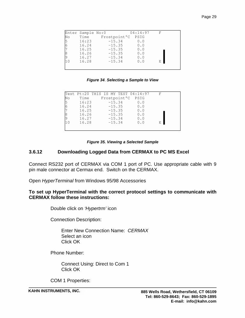
3.6.11 Viewing Logged Samples You may view either historical or real-time logged data on the Logging screen. (See section on Logging Menu) The screen also has a memory gauge that indicates the amount of logging memory used. If logging is in progress, the samples will be automatically scrolled. To view a sample not currently displayed on the screen, press the select key. Enter the number of the sample to view. Press the select key. The screen will display logged data, starting at the sample number entered. Alternatively, you may scroll down by pressing the # key. When the last sample has been displayed, the screen will wrap around to the first sample.
Figure 33. Logged Data
Test Pt:20 THIS IS MY TEST 04:14:97 F No Time Frostpoint°C PSIG 5 16:23 -15.34 0.0 6 16.24 -15.35 0.0 7 16.25 -15.35 0.0 8 16.26 -15.35 0.0 9 16.27 -15.34 0.0 10 16.28 -15.34 0.0 E
Sample number Time stamp
Main value
Auxiliary value
Memory gauge
KAHN INSTRUMENTS, INC.
Page 29
885 Wells Road, Wethersfield, CT 06109 Tel: 860-529-8643; Fax: 860-529-1895
E-mail: [email protected]
Figure 34. Selecting a Sample to View
Figure 35. Viewing a Selected Sample
3.6.12 Downloading Logged Data from CERMAX to PC MS Excel Connect RS232 port of CERMAX via COM 1 port of PC. Use appropriate cable with 9 pin male connector at Cermax end. Switch on the CERMAX. Open HyperTerminal from Windows 95/98 Accessories To set up HyperTerminal with the correct protocol settings to communicate with CERMAX follow these instructions: Double click on ‘Hypertrm’ icon Connection Description: Enter New Connection Name: CERMAX Select an icon Click OK Phone Number: Connect Using: Direct to Com 1 Click OK COM 1 Properties:
Enter Sample No:0 04:14:97 F No Time Frostpoint°C PSIG 5 16:23 -15.34 0.0 6 16.24 -15.35 0.0 7 16.25 -15.35 0.0 8 16.26 -15.35 0.0 9 16.27 -15.34 0.0 10 16.28 -15.34 0.0 E
Test Pt:20 THIS IS MY TEST 04:14:97 F No Time Frostpoint°C PSIG 5 16:23 -15.34 0.0 6 16.24 -15.35 0.0 7 16.25 -15.35 0.0 8 16.26 -15.35 0.0 9 16.27 -15.34 0.0 10 16.28 -15.34 0.0 E
KAHN INSTRUMENTS, INC.
Page 30
885 Wells Road, Wethersfield, CT 06109 Tel: 860-529-8643; Fax: 860-529-1895
E-mail: [email protected]
Port Settings: Bits per Second: 9600 Data bits: 8 Parity: None Stop bits: 1 Flow control: Xon, Xoff or None Click OK To perform data transfer: With HyperTerminal link made to CERMAX: Select Capture text from Transfer drop down menu Capture Test: Enter c:/filename.TXT
Note: Select file location and filename, TXT file extension should be used.
Click Start Type LOAD and press the ENTER key Wait until the file transfer is complete Click Stop Open Excel Click File, Open Select file as c:/filename.txt Select Type of Files: Text files Click Open Follow Text Import Wizard to select area of data to be transferred and to select column and date formats. Transfer complete
3.7 Serial Communication The CERMAX uses an RS232 serial interface to communicate with a standard terminal operating at 9600 baud, 8 data bits, 1 start bit, 1 stop bit, no parity. Using a set of terminal commands you can
Set a customer defined unit ID Define the keyboard response times Set the date and time

KAHN INSTRUMENTS, INC.
Page 31
885 Wells Road, Wethersfield, CT 06109 Tel: 860-529-8643; Fax: 860-529-1895
E-mail: [email protected]
Set the time to US or European format Download logged data for viewing on the terminal or importing into a spreadsheet Clear the Logging memory after a download
To confirm communication, connect the terminal to the CERMAX and switch on the CERMAX. You should see an opening message like this:
KAHN INSTRUMENTS, INC. CERMAX UNIT ID FRED SERIAL NO. C123 C45 SOFTWARE VERSION 1.90.00 :>
To view a list of available commands, type HELP. You will see the user menu like this:-
CLCK? READ THE REAL TIME CLOCK DATE=xx:xx:xx SET DATE TIME=xx:xx:xx SET TIME LANG=US US SETUP LANG=UK UK SETUP KDLY=xx SET KEY REPEAT DELAY IN 10mS UNITS (DEFAULT 100mS) KRPT=xx SET KEY REPEAT RATE IN 10mS UNITS (DEFAULT 100mS) ERAS CLEAR THE LOGGING MEMORY ID= ENTER A MACHINE ID (MAXIMUM 20 CHARACTERS) LOAD DOWNLOAD LOGGED DATA TO TERMINAL :>
3.7.1 Using Terminal Commands

KAHN INSTRUMENTS, INC.
Page 32
885 Wells Road, Wethersfield, CT 06109 Tel: 860-529-8643; Fax: 860-529-1895
E-mail: [email protected]
Function Enter Response Read the clock CLCK? DATE IS 04:14:97
TIME IS 16:43:15 Set the date DATE=04:14:97 DATE IS 04:14:97 Set the time TIME=10:30:00 TIME IS 10:30:00 Set the language format UK format = DDMMYY US format = MMDDYY
LANG=UK or LANG=US
LANGUAGE = UK or LANGUAGE = US
Select Field Mode FIELD UNIT CONFIGURED FOR SPOT CHECK Select Laboratory Mode LABUSE UNIT CONFIGURED FOR EXTENDED
MEASUREMENT MODE Set the key repeat delay This changes the response speed of the CERMAX keyboard. The delay time is entered in 10mS increments. The default is 100mS
KDLY=10 INITIAL KEY REPEAT DELAY SET TO 100 mS
Set the key repeat rate This changes the response speed of the CERMAX keyboard. The delay time is entered in 10mS increments. The default is 100mS
KRPT=10 KEY REPEAT INTERVAL SET TO 100 mS
Download logged data to a PC Downloading may not be done if logging is in progress. During downloading, all other CERMAX functions are suspended.
LOAD DOWNLOADING LOGGING FILES - PLEASE WAIT… DOWNLOAD SUCCESSFUL
Clearing the logging memory This command will delete all logged data stored in the CERMAX on board memory. Once cleared, it cannot be recovered.
ERAS CLEARING THE LOGGING MEMORY WILL TAKE A FEW SECONDS - PLEASE WAIT…. LOGGING MEMORY CLEARED
Enter a machine identifier ID=FRED Unit ID is FRED
3.7.2 Downloading Logged Data

KAHN INSTRUMENTS, INC.
Page 33
885 Wells Road, Wethersfield, CT 06109 Tel: 860-529-8643; Fax: 860-529-1895
E-mail: [email protected]
Once downloaded, the logged data may be viewed on the terminal or loaded into another package, such as a spreadsheet, for easier viewing. Data fields are in tab separated format. UNIT ID FRED Test Pt:0 MY TEST 04:15:97 No Date Time LB/MMSCF PSIG 0 04:15:97 14:59 2.30 1000.0 1 04:15:97 15:00 2.31 1000.0
| |
8 04:15:97 15:02 2.28 1000.0 9 04:15:97 15:03 2.28 1000.0 Example of downloaded data as viewed on the terminal.
3.8 Charging The CERMAX unit is powered by a rechargeable, detachable battery pack. The battery pack may be recharged either by:
a) Removing the battery pack from the instrument and charging via the supplied battery charging unit. b) Connecting the supplied battery charger via the charger socket on the rear of the CERMAX unit.
The unit may be used while charging. Charge time is up to 12 hours but can be up to 14 hours if the instrument is in use at the same time. WARNING Use only the supplied charger. CERMAX will display a Low Battery Warning if the power falls below the minimum recommended operating level. Battery should be recharged immediately. Failure to recharge the battery may result in the unit display to fail and the battery to deep discharge. If this does occur, battery should be recharged immediately. If left deeply discharged for extended periods, its ability to accept charge will be seriously affected. Do not short circuit the batteries.

KAHN INSTRUMENTS, INC.
Page 34
885 Wells Road, Wethersfield, CT 06109 Tel: 860-529-8643; Fax: 860-529-1895
E-mail: [email protected]
4. MECHANICAL INSTALLATION
4.1 General The instrument may have been supplied with a full accessory package. Please check that all the components listed on the packing check list are present.
4.2 Sampling Hints The Ceramic Sensor within CERMAX is designed to operate in a flowing gas stream. It is provided with a sensor sampling block that will enable a small sample of process gas to be diverted past the sensor before returning to the main gas stream or being bled off to atmosphere. See appendix 1 for the recommended sampling system. The general rules to be adhered to when arranging a sampling system are as follows: a) Make sure the sample is representative of the gas under test. The sample point should be as close to the critical measurement point as possible. For example in a glove box application, take the sample close to the exit of the glove box or at the point where work is being carried out, not at the gas entry point. b) Minimize volume in sample lines and potential for moisture ingress through joints. Try to avoid too many fittings or unnecessary tubing. Dead space in sample lines increases response time by holding water molecules that are more slowly released to the passing gas sample. c) Remove any particulate matter or liquid phase components from the gas sample. Particulates at high velocity can damage the sensor. Similarly, at low velocity they may "blind" the sensor and reduce its response speed. If particulates such as degraded desiccant or metal chips and rust are possible, use a particulate in-line filter. A coalescing filter should be used if there is any possibility of liquid or aerosol contamination. Kahn Technical Sales staff will be happy to give advice. d) Use high quality sample pipe and fittings. CERMAX is designed for use with 1/8” stainless steel or PTFE tubing. Always use the shortest run of tubing possible between two points. Use the lowest diameter tubing possible to reduce response time, but take care not to induce pressure differentials by inducing a too high flow rate through small diameter tubing.

KAHN INSTRUMENTS, INC.
Page 35
885 Wells Road, Wethersfield, CT 06109 Tel: 860-529-8643; Fax: 860-529-1895
E-mail: [email protected]
A sampling flow between 1 and 5 liters per minute (2-10 SCFH) will be satisfactory for the Sensor to operate correctly.
4.3 Response Characteristics Many factors will affect the speed at which the hygrometer will give a satisfactory result. It is much easier for the sensor to detect an increase in moisture content than to respond to a decrease. This is similar in principle to the way it is easy to make a sponge wet, but more difficult to dry it out afterwards. In practice, the time taken to dry down a sensor from ambient conditions to the operational dewpoint level of the process will normally be shorter than the time taken to dry down the process itself. Therefore when the sample line is installed into the system prior to system start-up there is normally no time lag before representative test results are obtained. When the instrument is first connected to an operational system, for example an air dryer exhaust, via a sampling tube with particulate filter, typically five minutes should be allowed for the tubing, any filters and the sensor to reach equilibrium with the sample gas. The actual time will depend on many factors including sample line lengths, flow rate, pressure and temperature of the air. Many factors affect the speed at which the instrument will give a satisfactory result. Most importantly, the that good sampling techniques must be observed - See previous section 4.2. After the instrument is first connected, a short period should be allowed for the system to reach equilibrium as the sample gas flows through the instrument. The actual time will depend on, among other things, sample line materials, length and flow rate. CERMAX is a portable hygrometer and, as such, has been designed to provide quick response and optimum accuracy under conditions of field use. The response characteristic of the product has been optimized for maximum accuracy between 15 and 90 minutes from connection of the gas under test. To obtain the best results, it is important to connect the CERMAX onto the sample flow prior to switching on the instrument. After pressing the ‘ON’ button and selecting your desired operating mode, wait for the completion of the short initiation sequence. After this, the instrument display will indicate a reading which is rapidly responding to the dewpoint/moisture content being measured, and will display a “Responding” message. When the actual dewpoint of the gas being measured is reached, the “Responding” message will change to “Stable”. If the instrument is measuring the same gas for periods in excess of 8 hours, a gradual reduction of the displayed moisture content may be observed. This is due to excess desiccation of the sensor and its measuring system and does not indicate a fault

KAHN INSTRUMENTS, INC.
Page 36
885 Wells Road, Wethersfield, CT 06109 Tel: 860-529-8643; Fax: 860-529-1895
E-mail: [email protected]
condition. Starting another measurement cycle returns normal operation after such periods of extended desiccation.
4.4 Which Gases to Measure CERMAX, by nature of its design, is suitable for measurement of the moisture content of a wide variety of gases. In general, if the gas (in conjunction with water vapor) is not corrosive to base metals then it will be suitable for measurement by the Hygrometer. However gases containing entrained solids or hydrocarbon mists should be filtered before presentation to the Sensor using a coalescing filter. If only particulate matter is present in the sample line then a particulate in-line filter is all that is required. Suitable filters are available from Kahn Instruments. If a very dry gas is to be measured which would be corrosive when becoming wet, e. g. chlorine air, the sensor must be purged with an inert gas immediately after use. This will prevent chlorine sample air in the sensor block contaminating the sensor. This hygrometer is not designed for use with potentially explosive gases.

KAHN INSTRUMENTS, INC.
Page 37
885 Wells Road, Wethersfield, CT 06109 Tel: 860-529-8643; Fax: 860-529-1895
E-mail: [email protected]
5. MAINTENANCE
5.1 General Routine maintenance of the CERMAX hygrometer is confined to regular re-calibrations. The standard calibration period is typically one year. The date that the next calibration is due is shown in the bottom right hand corner of the display. The re-calibration indicator will appear approximately six weeks before the end of the current calibration year. This re-calibration work can only be done by exposure of the Moisture Sensor to sample gases of known moisture content. Calibration services traceable to NIST are provided by Kahn Instruments. Contact Kahn Instruments or your local representative for further details. The frequency of re-calibrations required in order to maintain the performance of the CERMAX hygrometer is primarily dependent on the composition of the gas to which the Sensor is exposed, i.e. content of liquid and particulate contaminants, corrosive elements, etc. (refer elsewhere in this manual for guidance). In most applications annual re-calibration ensures that the stated accuracy of the CERMAX hygrometer is maintained. Re-calibration of the CERMAX hygrometer can be achieved either by return of the complete instrument or just the Sensor assembly. In either case, calibration will be undertaken using calibrated test equipment traceable to national standards. The CERMAX sensor can be exchanged for a freshly calibrated one which will be supplied with a detailed certificate of calibration traceable to national standards. The method of removal and replacement of a new sensor is described in section 5.2.
5.2 CERMAX Sensor Assembly Removal and Replacement. The CERMAX sensor assembly consists of the sensor and sensor p.c.b., the sensor block and gas connections. The sensor block acts as a guard for the sensor and it is NOT recommended that the sensor be removed from the sensor block as damage to the sensor may result. Kahn Instruments cannot accept CERMAX Sensors under a warranty claim for recalibration or exchange if the Sensor Assembly is not complete or if the Sensor has been removed from the Sensor block.

KAHN INSTRUMENTS, INC.
Page 38
885 Wells Road, Wethersfield, CT 06109 Tel: 860-529-8643; Fax: 860-529-1895
E-mail: [email protected]
5.2.1 Sensor Assembly Removal The CERMAX hygrometer has been designed for field operation only when in the measurement and transportation mode. Sensor assembly removal and exchange MUST be conducted in an appropriate service environment that provides adequate protection during this procedure. It is strongly recommended that this work is carried out by a service engineer/department. Please fully read the instructions before beginning. 1) Turn the hygrometer off. Disconnect any tubing from the external ports of the gas bulkheads, and replace the gas port blanking caps. Remove any connections made to the RS232, auxiliary input ports and battery charging port. Close the instrument front cover and place the instrument face down on a bench top. 2) Loosen and remove the six case sealing screws, shown in figure 36, and be sure that the sealing washers are not misplaced. 3) Fully open the bottom half of the case by using the rubber handle grip as a hinge point and lay the bottom half of the case on the bench top. CAUTION: The internal electronics of the CERMAX hygrometer will now be exposed. Care should be exercised when handling tools. 4) The CERMAX Sensor Assembly will now be exposed in the top half of the open instrument case. The Sensor assembly has three connectors attached at the sensor p.c.b. All three connectors must be disconnected from the Sensor assembly the single screw and washer from the sensor support bracket and set to one side. 5) Remove the single screw and washer from the sensor bracket and set aside. 6) Loosen and fully unscrew both 1/8” nuts connecting the sensor assembly to the internal ports of the gas bulkheads. The CERMAX Sensor Assembly may now be removed from the Instrument. 7) If a replacement CERMAX Sensor Assembly is available, proceed to the replacement instructions. If the removed Sensor assembly is to be returned to a Kahn Instruments, be sure to save the sensor support bracket securing screw and reseal the two instrument case halves.
5.2.2 Sensor Assembly Replacement 1) Place the Sensor Assembly into the case by inserting the 1/8” connections into the internal ports of the gas bulkheads. Finger tighten the nuts. 2) Replace the sensor support bracket screw and washer. Do not tighten.

KAHN INSTRUMENTS, INC.
Page 39
885 Wells Road, Wethersfield, CT 06109 Tel: 860-529-8643; Fax: 860-529-1895
E-mail: [email protected]
3) Tighten the 1/8” gas bulkhead nuts with a wrench until slight resistance is felt, then continue to tighten no more than one quarter of a full turn. 4) Tighten the sensor support bracket screw. 5) Reconnect the three sensor p.c.b. connectors, and make sure they are correctly and fully mated. The CERMAX Sensor Assembly is now fully installed. 6) Using the rubber handle grip as a hinge mechanism close the rear half of the case onto the front half. Ensure the case halves are fully mated along all edges . Replace the six case sealing washers and screws and tighten. The hygrometer is now ready for use. NOTE: When the hygrometer is next switched on the opening screen will thereafter display the new Sensor Serial number.

KAHN INSTRUMENTS, INC.
Page 40
885 Wells Road, Wethersfield, CT 06109 Tel: 860-529-8643; Fax: 860-529-1895
E-mail: [email protected]
Figure 36. CERMAX - Showing Sensor Replacement

KAHN INSTRUMENTS, INC.
Page 41
885 Wells Road, Wethersfield, CT 06109 Tel: 860-529-8643; Fax: 860-529-1895
E-mail: [email protected]
6. TECHNICAL SPECIFICATIONS Sensor Kahn Ceramic Moisture Sensor Gas wetted components 316 stainless steel Components Gas connections 1/8” Swagelok inlet and outlet fittings. Display Standard version: 240 x 64 dot matrix LCD Range Calibrated from -100 to +20 oC dewpoint; readings to -120 and +30 oC dewpoint Accuracy +/- 1 oC from -60 to +20 oC dewpoint;
+/- 2 oC from -100 to -60 oC dewpoint Resolution 0.1 oC dewpoint, 3 significant figures for other units Units oC, oF, K dewpoint
PPM(V) PPM(W) for air, N2, H2, CO2, natural gas %RH, gm-3 (natural gas) #/MMSCF (natural gas)
Secondary input 0-20 mA or 4-20 mA for temperature or pressure Data storage Up to 10,000 samples of primary and secondary variable,
time and date stamp and identification tag Communications RS232C for stored data Power Internal re-chargeable battery pack (removable) charged
by external a.c. powered 6V charger (supplied). 24 hours normal operation between charges. Charge time is up to 12 hours but can be up to 14 hours if the instrument is in use at the same time.
Case Custom polyurethane case with integral padded carry handle
Dimensions 250W x 300D x 150H mm approx. Weight 8.8 lbs (3 kg) Ingress protection IP65 Operating temperature -20 to +50 OC Storage temperature -40 to +70 oC Operating pressure max 6000 PSIG Flow rate 1 to 5 Normal liters per minute/ 2-10 standard cubic feet
per hour (SCFH) Optional accessories Carrying bag Shoulder strap Sample system Spare battery pack
KAHN INSTRUMENTS, INC.
Page 42
885 Wells Road, Wethersfield, CT 06109 Tel: 860-529-8643; Fax: 860-529-1895
E-mail: [email protected]
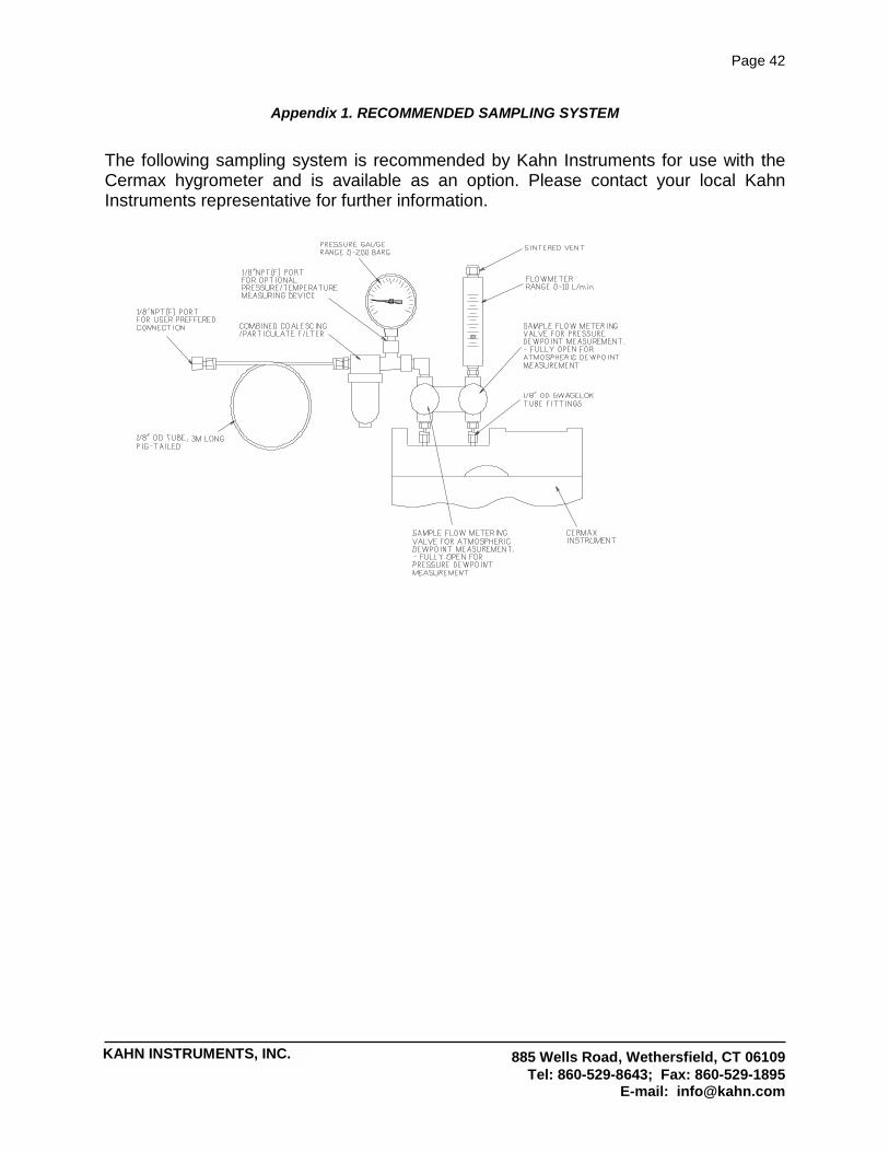
Appendix 1. RECOMMENDED SAMPLING SYSTEM
The following sampling system is recommended by Kahn Instruments for use with the Cermax hygrometer and is available as an option. Please contact your local Kahn Instruments representative for further information.