ambient weather ws-3000 thermo-hygrometer, dew...
TRANSCRIPT
Version 1.3 ©Copyright 2016, Ambient LLC. All Rights Reserved. Page 1
Ambient Weather WS-3000 Thermo-Hygrometer, Dew
Point, Heat Index Wireless Monitor with Graphing,
Alarming, and Radio Controlled Clock User Manual
Table of Contents
1 Introduction ..................................................................................................................................... 3 2 Getting Started ................................................................................................................................ 3
2.1 Parts List ................................................................................................................................. 3 2.2 Recommend Tools .................................................................................................................. 3 2.3 Thermo-Hygrometer Sensor Set Up ....................................................................................... 3 2.4 Display Console Set Up ......................................................................................................... 5
2.4.1 Display Console Layout ......................................................................................................... 6 2.4.2 Sensor Operation Verification ............................................................................................ 7
3 Remote Sensor Installation ............................................................................................................. 7 4 Console Operation........................................................................................................................... 8
4.1 Setup Mode ............................................................................................................................ 8 4.1.1 Display Selection ............................................................................................................... 9 4.1.2 Graph Time ...................................................................................................................... 10 4.1.3 Time Format ..................................................................................................................... 11 4.1.4 Date Format ...................................................................................................................... 11 4.1.5 Date and Time Format ...................................................................................................... 11 4.1.6 Temperature Units of Measure ......................................................................................... 12
4.2 Calibration ............................................................................................................................ 12 4.2.1 Notes about Calibration .................................................................................................... 14 4.2.2 Humidity Calibration Methods ......................................................................................... 14 4.2.3 Temperature Calibration Methods ........................................................................................ 15
4.3 Min / Max and Alarm Mode ................................................................................................. 15 4.3.1 Min / Max ......................................................................................................................... 15 4.3.2 Alarms .............................................................................................................................. 16
4.4 Factory Settings .................................................................................................................... 19 4.4.1 Factory Reset .................................................................................................................... 19 4.4.2 Clear Max/Min Values ..................................................................................................... 20 4.4.3 Re-register Sensors ........................................................................................................... 20 4.4.4 About ................................................................................................................................ 20 4.4.5 Language .......................................................................................................................... 21 4.4.6 Back Light ........................................................................................................................ 21
5 Other Features ............................................................................................................................... 22 5.1 Radio Controlled Clock (RCC) ............................................................................................ 22 5.2 SD Card Export and Firmware Updates ............................................................................... 22
5.2.1 SD Data Export ................................................................................................................ 23 5.2.2 Back Up Graph Data ........................................................................................................ 23 5.2.3 Firmware Updates ............................................................................................................ 23
5.3 PC Software.......................................................................................................................... 24 5.3.1 Getting Started ................................................................................................................. 24 5.3.2 Time, Date and Display Setup .......................................................................................... 25

Version 1.3 ©Copyright 2016, Ambient LLC. All Rights Reserved. Page 2
5.3.3 Alarm Settings .................................................................................................................. 26 5.3.4 Calibration ........................................................................................................................ 27 5.3.5 SDCard File ...................................................................................................................... 27
6 Best Practices for Wireless Communication ................................................................................. 29 7 Glossary of Terms ......................................................................................................................... 30 8 Accessories ................................................................................................................................... 30 9 Specifications ................................................................................................................................ 30
9.1 Wireless Specifications ........................................................................................................ 30 9.2 Measurement Specifications ................................................................................................. 30 9.3 Power Consumption ............................................................................................................. 30
10 Troubleshooting Guide ............................................................................................................. 31 11 Liability Disclaimer .................................................................................................................. 32 12 FCC Statement .......................................................................................................................... 32 13 Warranty Information ............................................................................................................... 33

Version 1.3 ©Copyright 2016, Ambient LLC. All Rights Reserved. Page 3
1 Introduction Thank you for your purchase of the Ambient Weather WS-3000 Thermo-Hygrometer, Dew Point, Heat
Index Wireless Monitor with Graphing, Alarming, and Radio Controlled Clock. The following user
guide provides step by step instructions for installation, operation and troubleshooting. To download
the latest manual and additional troubleshooting tips, please visit:
http://ambientweather.wikispaces.com/ws3000
2 Getting Started
Note: The power up sequence must be performed in the order shown in this section (insert
batteries in the remote transmitter(s) first, Display Console second).
The WS-3000 weather station consists of a display console (receiver), and up to 5 thermo-hygrometers
(remote transmitters), based on your order configuration.
2.1 Parts List QTY Item
1 Display Console
Frame Dimensions (LxHxW): 4.5 x 3.75 x 1.5 in
LCD Dimensions (LxW): 3.75 x 2.25”
* Thermo-hygrometer transmitter (WH31)
Dimensions (LxHxW): 4.75” x 1.5” x 0.6”
1 USB Cable for PC Connection
* 1,2,3,4, or 5, based on your order configuration.
2.2 Recommend Tools Hammer and nail for hanging remote thermo-hygrometer transmitter(s).
2.3 Thermo-Hygrometer Sensor Set Up
Note: Do not use rechargeable batteries. We recommend fresh alkaline batteries for outdoor
temperature ranges between -4 °F and 140 °F and fresh lithium batteries for outdoor temperature
ranges between -40 °F and 140 °F.
Version 1.3 ©Copyright 2016, Ambient LLC. All Rights Reserved. Page 4
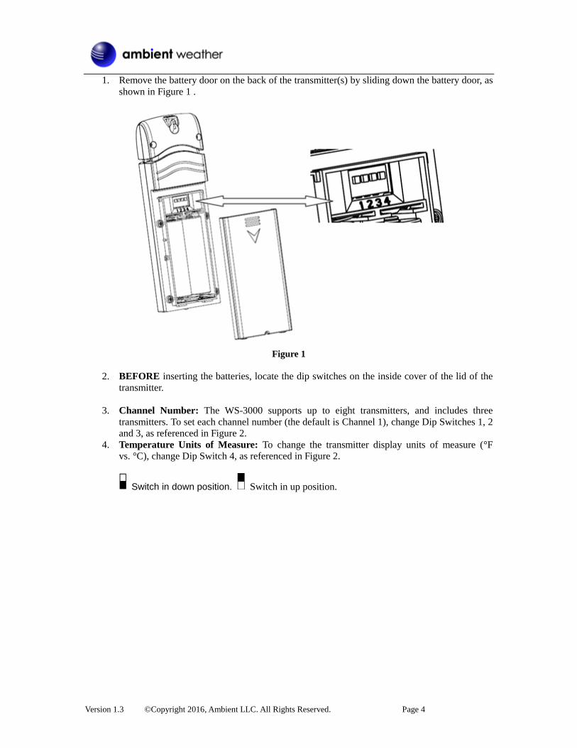
1. Remove the battery door on the back of the transmitter(s) by sliding down the battery door, as
shown in Figure 1 .
Figure 1
2. BEFORE inserting the batteries, locate the dip switches on the inside cover of the lid of the
transmitter.
3. Channel Number: The WS-3000 supports up to eight transmitters, and includes three
transmitters. To set each channel number (the default is Channel 1), change Dip Switches 1, 2
and 3, as referenced in Figure 2.
4. Temperature Units of Measure: To change the transmitter display units of measure (°F
vs. °C), change Dip Switch 4, as referenced in Figure 2.
Switch in down position. Switch in up position.

Version 1.3 ©Copyright 2016, Ambient LLC. All Rights Reserved. Page 5
Figure 2
5. Insert two AA batteries.
6. Verify the correct channel number (CH) and temperature units of measure (°F vs. °C) are on
the display, as shown in Figure 3.
Figure 3
(1) temperature
(2) temperature units (°F vs. °C) (3) channel number (4) relative humidity
7. Close the battery door.
8. Repeat for the additional remote transmitters, verifying each remote is on a different channel.
2.4 Display Console Set Up 1. Move the transmitters(s) about 5 to 10’ away from the display console (if the transmitters are
too close, they may not be received by the display console). With multiple transmitters, make
sure all transmitters are powered up and displaying different channels on the display.
2. Connect the console to AC power with the included AC adapter (Figure 4).
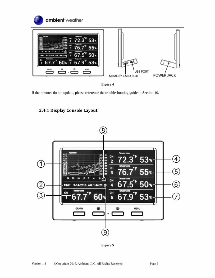
Version 1.3 ©Copyright 2016, Ambient LLC. All Rights Reserved. Page 6
Figure 4
If the remotes do not update, please reference the troubleshooting guide in Section 10.
2.4.1 Display Console Layout
Figure 5

Version 1.3 ©Copyright 2016, Ambient LLC. All Rights Reserved. Page 7
No Description No Description
1 Graph for Temperature/Dew point/heat
index/humidity of Indoor/outdoor
sensors.
6 Outdoor Temperature/Dew point/heat
index/humidity for channel 4 and other
channels defined to be displayed in
CH4 area.
2 Date and time. 7 Outdoor Temperature/Dew point/heat
index/humidity for channel 5 and other
channels defined to be displayed in
CH5 area.
3 Outdoor Temperature/Dew point/heat
index/humidity for channel 1 and other
channels defined to be displayed in CH1
area.
8 Alarm Icon.
4 Outdoor Temperature/Dew point/heat
index/humidity for channel 2 and other
channels defined to be displayed in CH2
area.
9 Radio Controlled Clock reception icon.
5 Outdoor Temperature/Dew point/heat
index/humidity for channel 3 and other
channels defined to be displayed in CH3
area.
2.4.2 Sensor Operation Verification Verify the humidity sensors match closely with all of the sensors in the same location (about 5 to 10’
apart). The sensors should agree within 10% (the accuracy is ± 5%). Allow about 30 minutes for all
sensors to stabilize. The humidity can be adjusted or calibrated later to match each other a known
source.
Verify the temperature sensors match closely with all of the sensors in the same location (about 5 to
10’ apart). The sensors should be within 4°F (the accuracy is ± 2°F). Allow about 30 minutes for all
sensors to stabilize. The temperature can be adjusted or calibrated later to match each other or a
known source.
3 Remote Sensor Installation If you mount one or more of the sensors outside, it is recommended you mount the sensor in a shaded
area. Direct sunlight and radiant heat sources will result in inaccurate temperature readings. Although
the sensors are water resistant, it is best to mount in a well-protected area, such as under an eve. Use a
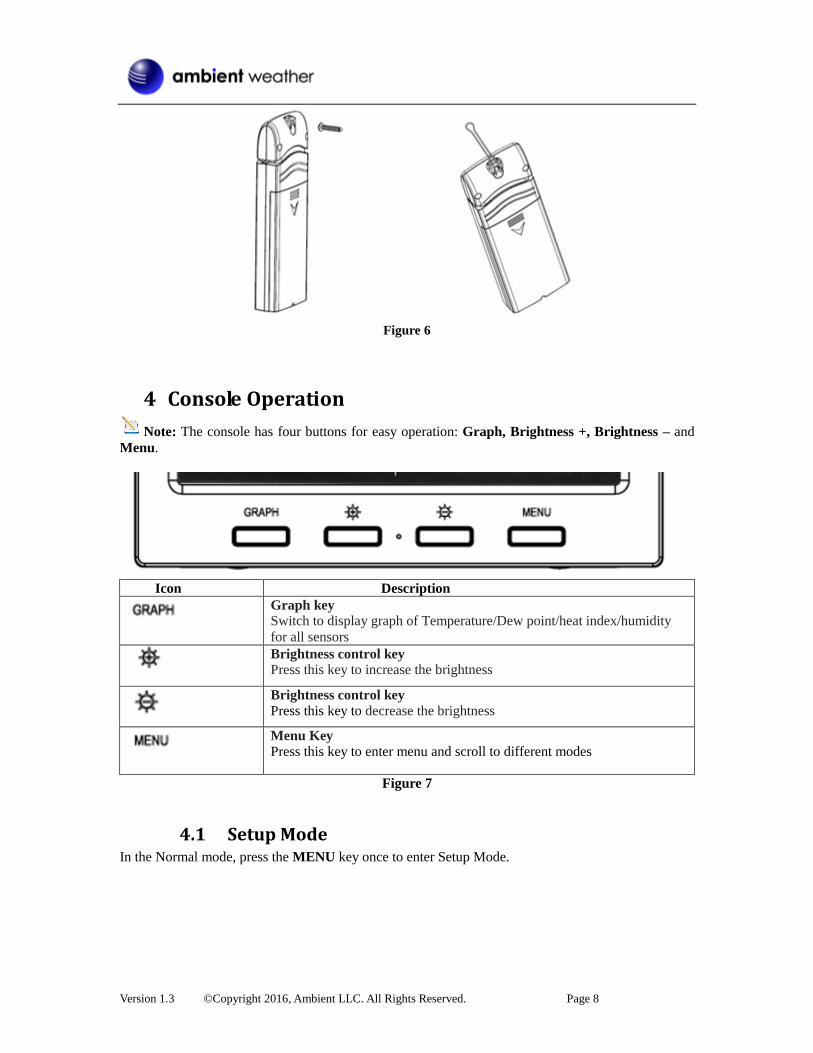
screw to affix the remote sensor to the wall, as shown in Figure 6.
Alternately, you can hang the sensor with fishing wire or a string. This insures the sensor does not
come into contact with any radiant heat source.
Version 1.3 ©Copyright 2016, Ambient LLC. All Rights Reserved. Page 8
Figure 6
4 Console Operation
Note: The console has four buttons for easy operation: Graph, Brightness +, Brightness – and
Menu.
Icon Description
Graph key Switch to display graph of Temperature/Dew point/heat index/humidity
for all sensors
Brightness control key Press this key to increase the brightness
Brightness control key
Press this key to decrease the brightness
Menu Key
Press this key to enter menu and scroll to different modes
Figure 7
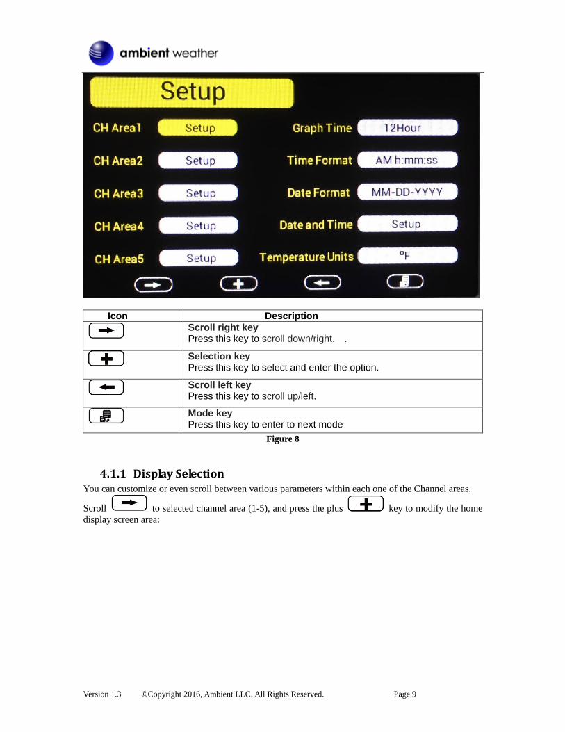
4.1 Setup Mode In the Normal mode, press the MENU key once to enter Setup Mode.
Version 1.3 ©Copyright 2016, Ambient LLC. All Rights Reserved. Page 9
Icon Description
Scroll right key Press this key to scroll down/right. .
Selection key Press this key to select and enter the option.
Scroll left key Press this key to scroll up/left.
Mode key Press this key to enter to next mode
Figure 8
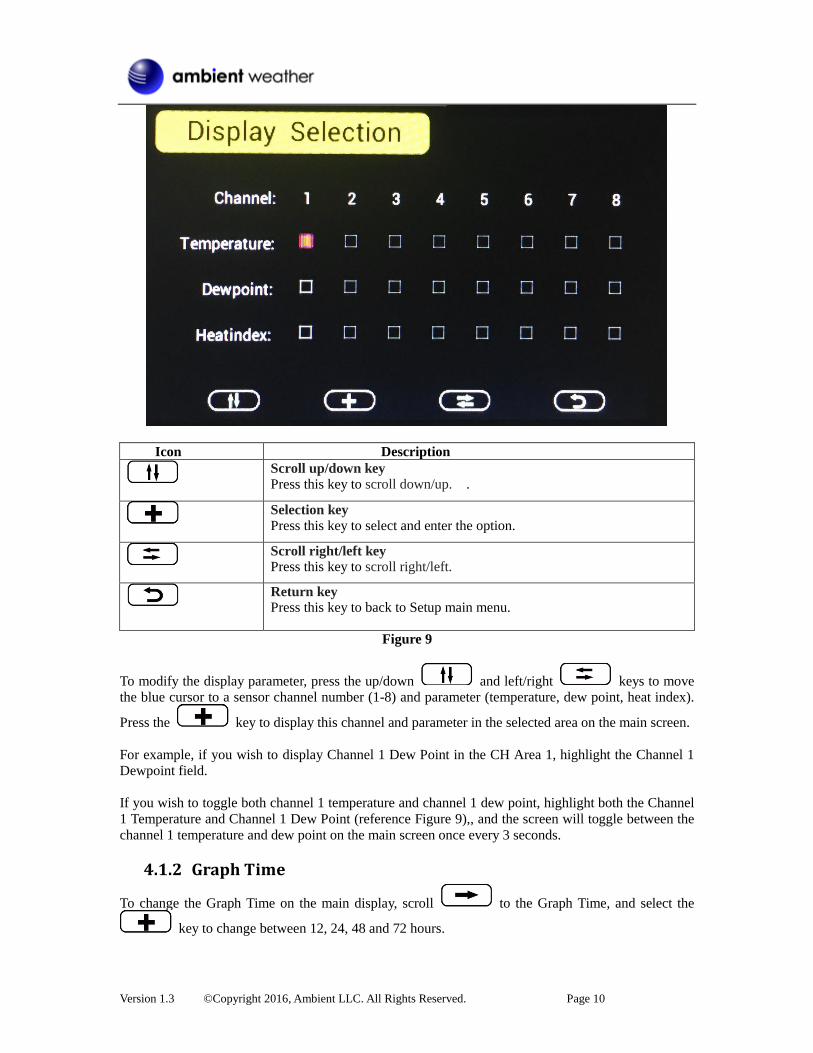
4.1.1 Display Selection You can customize or even scroll between various parameters within each one of the Channel areas.
Scroll to selected channel area (1-5), and press the plus key to modify the home
display screen area:
Version 1.3 ©Copyright 2016, Ambient LLC. All Rights Reserved. Page 10
Icon Description
Scroll up/down key
Press this key to scroll down/up. .
Selection key
Press this key to select and enter the option.
Scroll right/left key Press this key to scroll right/left.
Return key Press this key to back to Setup main menu.
Figure 9
To modify the display parameter, press the up/down and left/right keys to move
the blue cursor to a sensor channel number (1-8) and parameter (temperature, dew point, heat index).
Press the key to display this channel and parameter in the selected area on the main screen.
For example, if you wish to display Channel 1 Dew Point in the CH Area 1, highlight the Channel 1
Dewpoint field.
If you wish to toggle both channel 1 temperature and channel 1 dew point, highlight both the Channel
1 Temperature and Channel 1 Dew Point (reference Figure 9),, and the screen will toggle between the
channel 1 temperature and dew point on the main screen once every 3 seconds.
4.1.2 Graph Time
To change the Graph Time on the main display, scroll to the Graph Time, and select the
key to change between 12, 24, 48 and 72 hours.

Version 1.3 ©Copyright 2016, Ambient LLC. All Rights Reserved. Page 11
Note: When the graph interval is changed, the graph will reset and require rebuidling.
4.1.3 Time Format
To change the Time Format on the main display, scroll to the Time Format, and select the
key to change between AM h:mm:ss, hh:mm:ss AM (12 hour time format) and h:mm:ss (24
hour time format)
4.1.4 Date Format
To change the Date Format on the main display, scroll to the Date Format, and select the
key to change between MM-DD-YYYY, DD-MM-YYYY and YYYY-MM-DD.
4.1.5 Date and Time Format
Figure 10
The console receives the radio controlled time signal from any one of the wireless sensors. The time
and date will set automatically, and adjust for Daylight Savings Time (DST). To work properly, you
must enter the time zone and DST. You can also manually enter the time.
To manually change the time and data settings, scroll to the field you wish to change, and
press the or key to adjust up or down.
Turn ON the DST setting, unless you reside in Arizona or Hawaii, which do not observe Daylight
Savings Time.
Adjust your time zone according to the table below:
Hours from
GMT
Time Zone Cities
-12 IDLW: International Date Line West ---
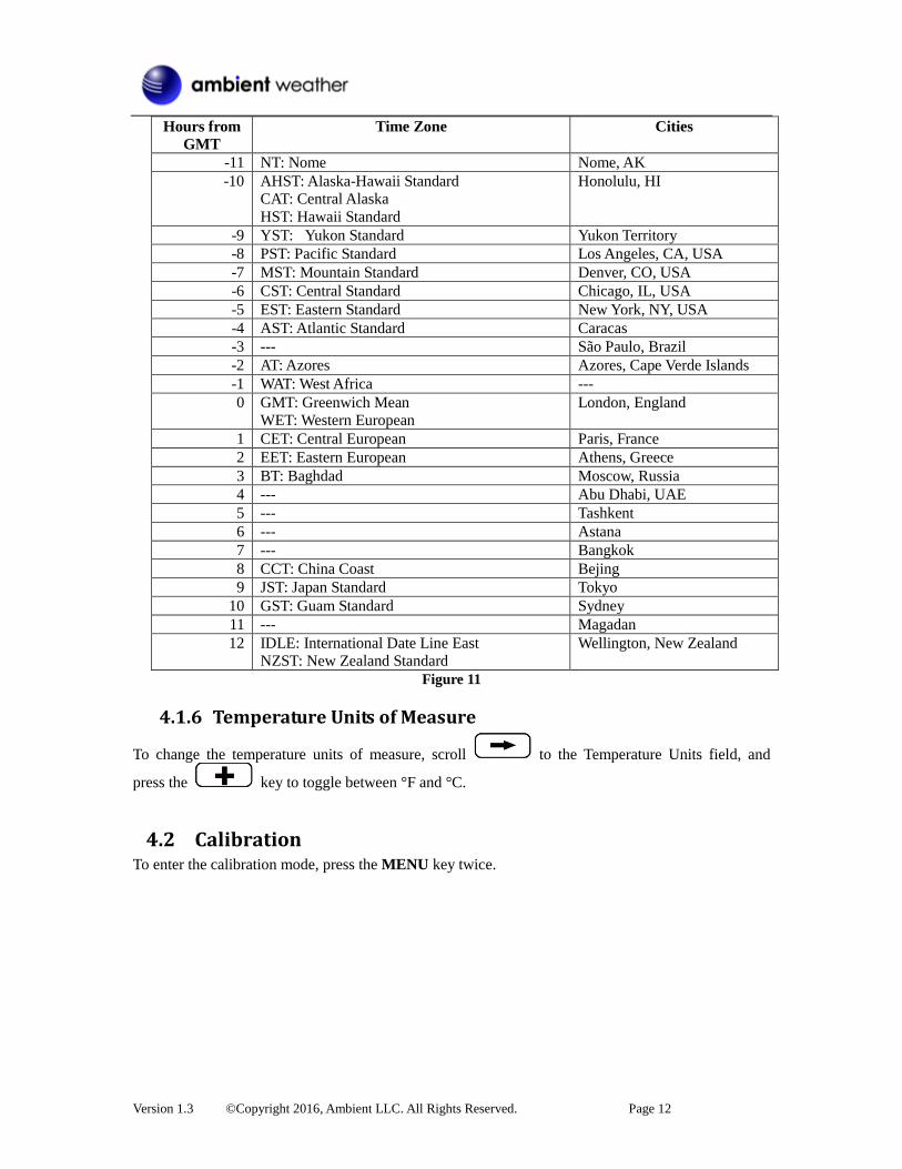
Version 1.3 ©Copyright 2016, Ambient LLC. All Rights Reserved. Page 12
Hours from
GMT
Time Zone Cities
-11 NT: Nome Nome, AK
-10 AHST: Alaska-Hawaii Standard
CAT: Central Alaska
HST: Hawaii Standard
Honolulu, HI
-9 YST: Yukon Standard Yukon Territory
-8 PST: Pacific Standard Los Angeles, CA, USA
-7 MST: Mountain Standard Denver, CO, USA
-6 CST: Central Standard Chicago, IL, USA
-5 EST: Eastern Standard New York, NY, USA
-4 AST: Atlantic Standard Caracas
-3 --- São Paulo, Brazil
-2 AT: Azores Azores, Cape Verde Islands
-1 WAT: West Africa ---
0 GMT: Greenwich Mean
WET: Western European
London, England
1 CET: Central European Paris, France
2 EET: Eastern European Athens, Greece
3 BT: Baghdad Moscow, Russia
4 --- Abu Dhabi, UAE
5 --- Tashkent
6 --- Astana
7 --- Bangkok
8 CCT: China Coast Bejing
9 JST: Japan Standard Tokyo
10 GST: Guam Standard Sydney
11 --- Magadan
12 IDLE: International Date Line East
NZST: New Zealand Standard
Wellington, New Zealand
Figure 11
4.1.6 Temperature Units of Measure
To change the temperature units of measure, scroll to the Temperature Units field, and
press the key to toggle between °F and °C.
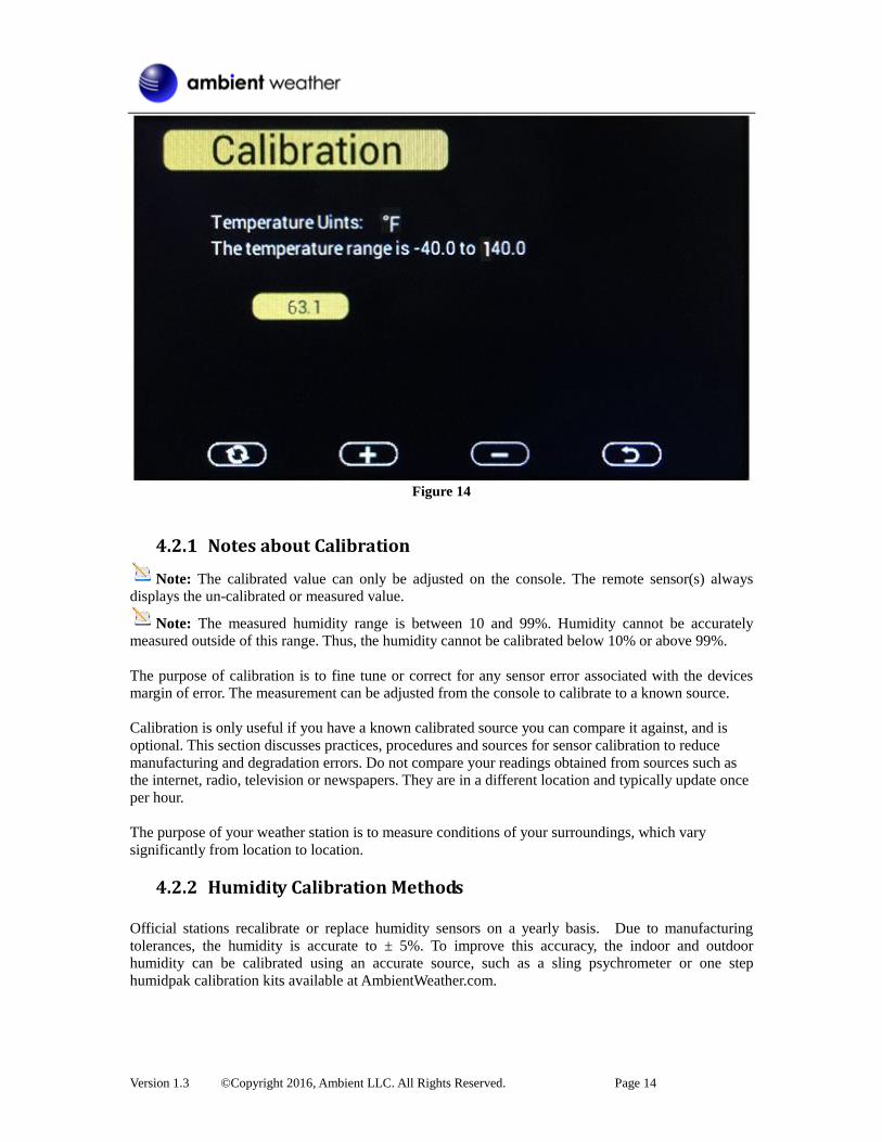
4.2 Calibration To enter the calibration mode, press the MENU key twice.

Version 1.3 ©Copyright 2016, Ambient LLC. All Rights Reserved. Page 13
Figure 12
Icon Description
Scroll down/right key Press this key to scroll down/right. .
Selection/value increase key Press this key to select parameter and enter the calibration interface. Increase the value during calibration.
Value Decrease key Decrease the value during calibration.
Scroll up/left key Press this key to scroll up/left.
Mode key Press this key to enter to next mode
Return Key Back to main menu of calibration mode.
Resume Key Cancel the calibration and resume.
Figure 13
Scroll to the temperature or humidity field you wish to calibrate, press the key
to perform the calibration, and press the or key to match your calibration source.
Version 1.3 ©Copyright 2016, Ambient LLC. All Rights Reserved. Page 14
Figure 14
4.2.1 Notes about Calibration
Note: The calibrated value can only be adjusted on the console. The remote sensor(s) always
displays the un-calibrated or measured value.
Note: The measured humidity range is between 10 and 99%. Humidity cannot be accurately
measured outside of this range. Thus, the humidity cannot be calibrated below 10% or above 99%.
The purpose of calibration is to fine tune or correct for any sensor error associated with the devices
margin of error. The measurement can be adjusted from the console to calibrate to a known source.
Calibration is only useful if you have a known calibrated source you can compare it against, and is
optional. This section discusses practices, procedures and sources for sensor calibration to reduce
manufacturing and degradation errors. Do not compare your readings obtained from sources such as
the internet, radio, television or newspapers. They are in a different location and typically update once
per hour.
The purpose of your weather station is to measure conditions of your surroundings, which vary
significantly from location to location.
4.2.2 Humidity Calibration Methods
Official stations recalibrate or replace humidity sensors on a yearly basis. Due to manufacturing
tolerances, the humidity is accurate to ± 5%. To improve this accuracy, the indoor and outdoor
humidity can be calibrated using an accurate source, such as a sling psychrometer or one step
humidpak calibration kits available at AmbientWeather.com.
Version 1.3 ©Copyright 2016, Ambient LLC. All Rights Reserved. Page 15
4.2.3 Temperature Calibration Methods Temperature errors can occur when a sensor is placed too close to a heat source (such as a building
structure, the ground or trees).
To calibrate temperature, we recommend a mercury or red spirit (fluid) thermometer. Bi-metal (dial)
and other digital thermometers are not a good source and have their own margin of error. Using a local
weather station in your area is also a poor source due to changes in location, timing (airport weather
stations are only updated once per hour) and possible calibration errors (many official weather stations
are not properly installed and calibrated).
Place the sensor in a shaded, controlled environment next to the fluid thermometer, and allow the
sensor to stabilize for 48 hours. Compare this temperature to the fluid thermometer and adjust the
console to match the fluid thermometer.
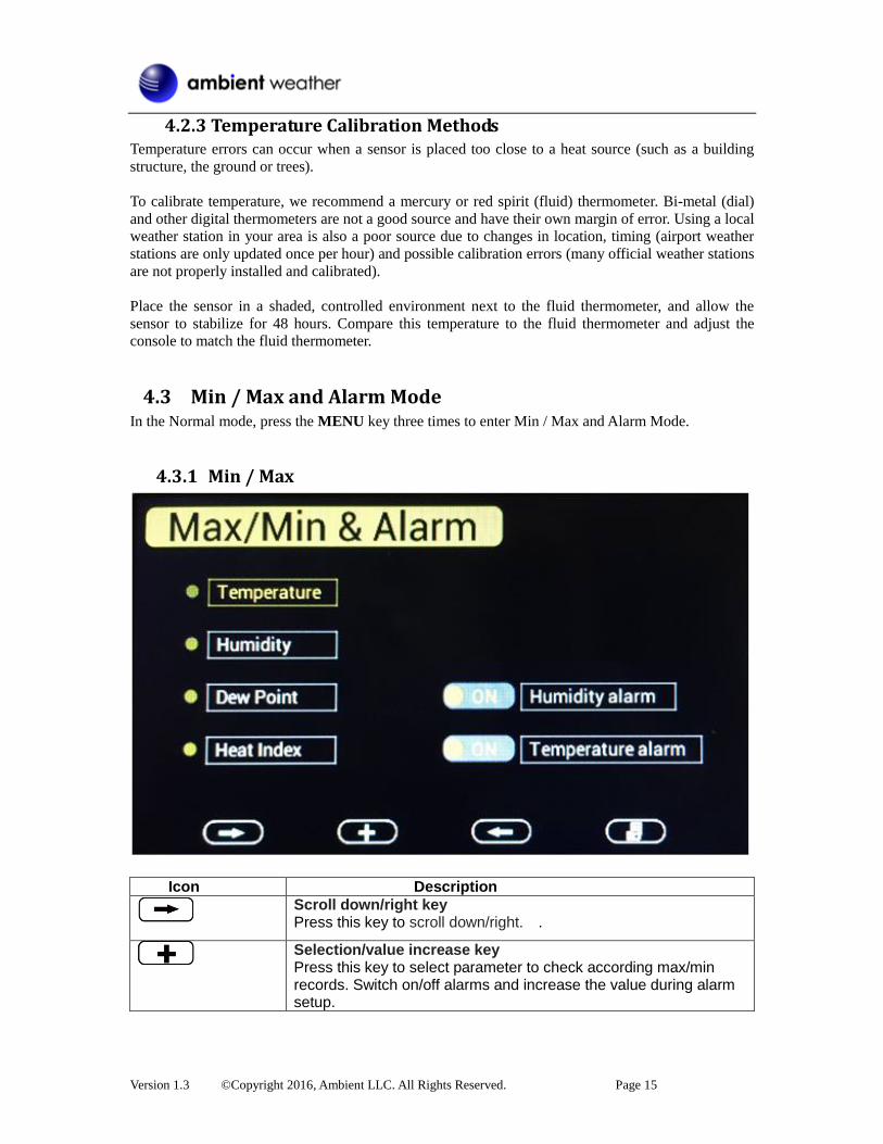
4.3 Min / Max and Alarm Mode In the Normal mode, press the MENU key three times to enter Min / Max and Alarm Mode.
4.3.1 Min / Max
Icon Description
Scroll down/right key Press this key to scroll down/right. .
Selection/value increase key Press this key to select parameter to check according max/min records. Switch on/off alarms and increase the value during alarm setup.
Version 1.3 ©Copyright 2016, Ambient LLC. All Rights Reserved. Page 16
Value Decrease key Decrease the value during alarm setup.
Scroll up/left key Press this key to scroll up/left.
Mode key Press this key to enter to next mode
Return Key Back to main menu of calibration mode.
Resume Key Cancel the calibration and resume.
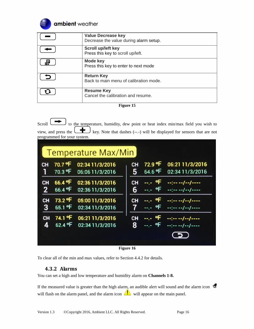
Figure 15
Scroll to the temperature, humidity, dew point or heat index min/max field you wish to
view, and press the key. Note that dashes (--.-) will be displayed for sensors that are not
programmed for your system.
Figure 16
To clear all of the min and max values, refer to Section 4.4.2 for details.
4.3.2 Alarms You can set a high and low temperature and humidity alarm on Channels 1-8.
If the measured value is greater than the high alarm, an audible alert will sound and the alarm icon
will flash on the alarm panel, and the alarm icon will appear on the main panel.
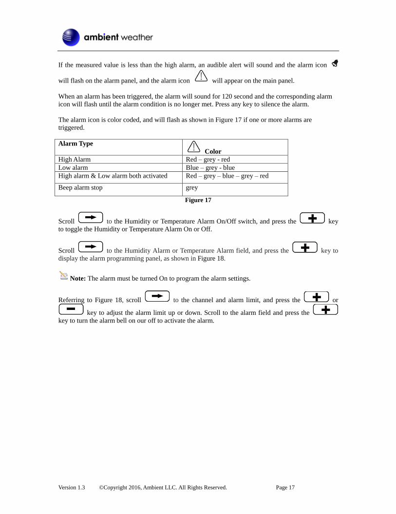
Version 1.3 ©Copyright 2016, Ambient LLC. All Rights Reserved. Page 17
If the measured value is less than the high alarm, an audible alert will sound and the alarm icon
will flash on the alarm panel, and the alarm icon will appear on the main panel.
When an alarm has been triggered, the alarm will sound for 120 second and the corresponding alarm
icon will flash until the alarm condition is no longer met. Press any key to silence the alarm.
The alarm icon is color coded, and will flash as shown in Figure 17 if one or more alarms are
triggered.
Alarm Type
Color
High Alarm Red – grey - red
Low alarm Blue – grey - blue
High alarm & Low alarm both activated Red – grey – blue – grey – red
Beep alarm stop grey
Figure 17
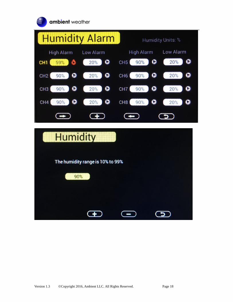
Scroll to the Humidity or Temperature Alarm On/Off switch, and press the key
to toggle the Humidity or Temperature Alarm On or Off.
Scroll to the Humidity Alarm or Temperature Alarm field, and press the key to
display the alarm programming panel, as shown in Figure 18.
Note: The alarm must be turned On to program the alarm settings.
Referring to Figure 18, scroll to the channel and alarm limit, and press the or
key to adjust the alarm limit up or down. Scroll to the alarm field and press the
key to turn the alarm bell on our off to activate the alarm.
Version 1.3 ©Copyright 2016, Ambient LLC. All Rights Reserved. Page 18

Version 1.3 ©Copyright 2016, Ambient LLC. All Rights Reserved. Page 19
Icon Description
Scroll down/right key Press this key to scroll down/right. .
Selection/value increase key Press this key to select parameter to set alarm thresholds and turn on the alarm icon. Red alarm icon is high alarm. Blue one is low alarm.
Value Decrease key Decrease the value during alarm setup.
Scroll up/left key Press this key to scroll up/left.
Mode key Press this key to back to main menu or enter to next mode
Return Key Back to main menu of alarm menu.
Figure 18
4.4 Factory Settings To enter the Factory mode, press the MENU key four times.
Figure 19
4.4.1 Factory Reset
To restore to factory default, scroll to the Factory Reset field and press to clear
all settings and restore to factory default.
Version 1.3 ©Copyright 2016, Ambient LLC. All Rights Reserved. Page 20
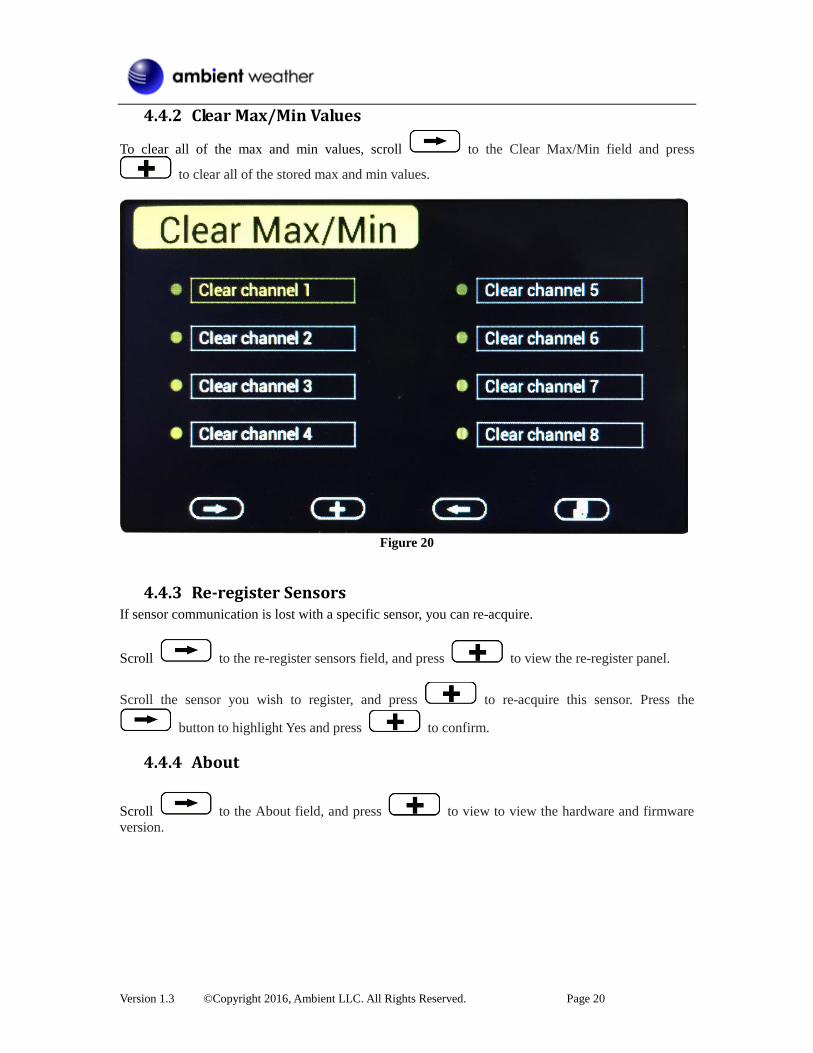
4.4.2 Clear Max/Min Values
To clear all of the max and min values, scroll to the Clear Max/Min field and press
to clear all of the stored max and min values.
Figure 20
4.4.3 Re-register Sensors If sensor communication is lost with a specific sensor, you can re-acquire.
Scroll to the re-register sensors field, and press to view the re-register panel.
Scroll the sensor you wish to register, and press to re-acquire this sensor. Press the
button to highlight Yes and press to confirm.
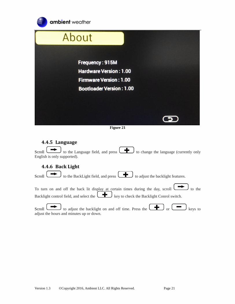
4.4.4 About
Scroll to the About field, and press to view to view the hardware and firmware
version.
Version 1.3 ©Copyright 2016, Ambient LLC. All Rights Reserved. Page 21
Figure 21
4.4.5 Language
Scroll to the Language field, and press to change the language (currently only
English is only supported).
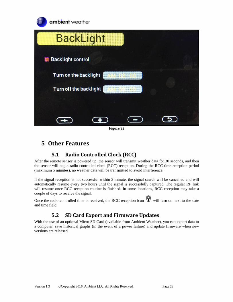
4.4.6 Back Light
Scroll to the BackLight field, and press to adjust the backlight features.
To turn on and off the back lit display at certain times during the day, scroll to the
Backlight control field, and select the key to check the Backlight Conrol switch.
Scroll to adjust the backlight on and off time. Press the or keys to
adjust the hours and minutes up or down.
Version 1.3 ©Copyright 2016, Ambient LLC. All Rights Reserved. Page 22
Figure 22
5 Other Features
5.1 Radio Controlled Clock (RCC) After the remote sensor is powered up, the sensor will transmit weather data for 30 seconds, and then
the sensor will begin radio controlled clock (RCC) reception. During the RCC time reception period
(maximum 5 minutes), no weather data will be transmitted to avoid interference.
If the signal reception is not successful within 3 minute, the signal search will be cancelled and will
automatically resume every two hours until the signal is successfully captured. The regular RF link
will resume once RCC reception routine is finished. In some locations, RCC reception may take a
couple of days to receive the signal.
Once the radio controlled time is received, the RCC reception icon will turn on next to the date
and time field.
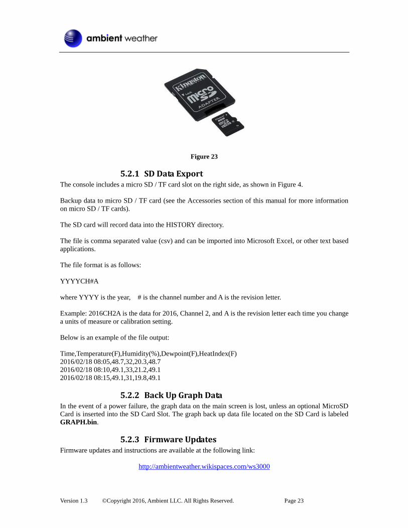
5.2 SD Card Export and Firmware Updates With the use of an optional Micro SD Card (available from Ambient Weather), you can export data to
a computer, save historical graphs (in the event of a power failure) and update firmware when new
versions are released.
Version 1.3 ©Copyright 2016, Ambient LLC. All Rights Reserved. Page 23
Figure 23
5.2.1 SD Data Export The console includes a micro SD / TF card slot on the right side, as shown in Figure 4.
Backup data to micro SD / TF card (see the Accessories section of this manual for more information
on micro SD / TF cards).
The SD card will record data into the HISTORY directory.
The file is comma separated value (csv) and can be imported into Microsoft Excel, or other text based
applications.
The file format is as follows:
YYYYCH#A
where YYYY is the year, # is the channel number and A is the revision letter.
Example: 2016CH2A is the data for 2016, Channel 2, and A is the revision letter each time you change
a units of measure or calibration setting.
Below is an example of the file output:
Time,Temperature(F),Humidity(%),Dewpoint(F),HeatIndex(F)
2016/02/18 08:05,48.7,32,20.3,48.7
2016/02/18 08:10,49.1,33,21.2,49.1
2016/02/18 08:15,49.1,31,19.8,49.1
5.2.2 Back Up Graph Data In the event of a power failure, the graph data on the main screen is lost, unless an optional MicroSD
Card is inserted into the SD Card Slot. The graph back up data file located on the SD Card is labeled
GRAPH.bin.
5.2.3 Firmware Updates Firmware updates and instructions are available at the following link:
http://ambientweather.wikispaces.com/ws3000
Version 1.3 ©Copyright 2016, Ambient LLC. All Rights Reserved. Page 24
5.3 PC Software Optional PC Software is available for download.
The software features:
Live Data Display
Program Date and Time
Program Custom Display
Set Alarms
Calibrate Temperature and Humidity
Export and Graph Data from the SD Card
Sync Date and Time from the Computer
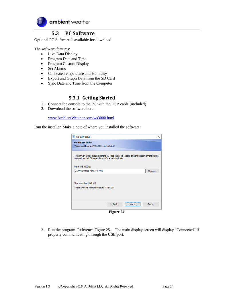
5.3.1 Getting Started 1. Connect the console to the PC with the USB cable (included)
2. Download the software here:
www.AmbientWeather.com/ws3000.html
Run the installer. Make a note of where you installed the software:
Figure 24
3. Run the program. Reference Figure 25. The main display screen will display “Connected” if
properly communicating through the USB port.
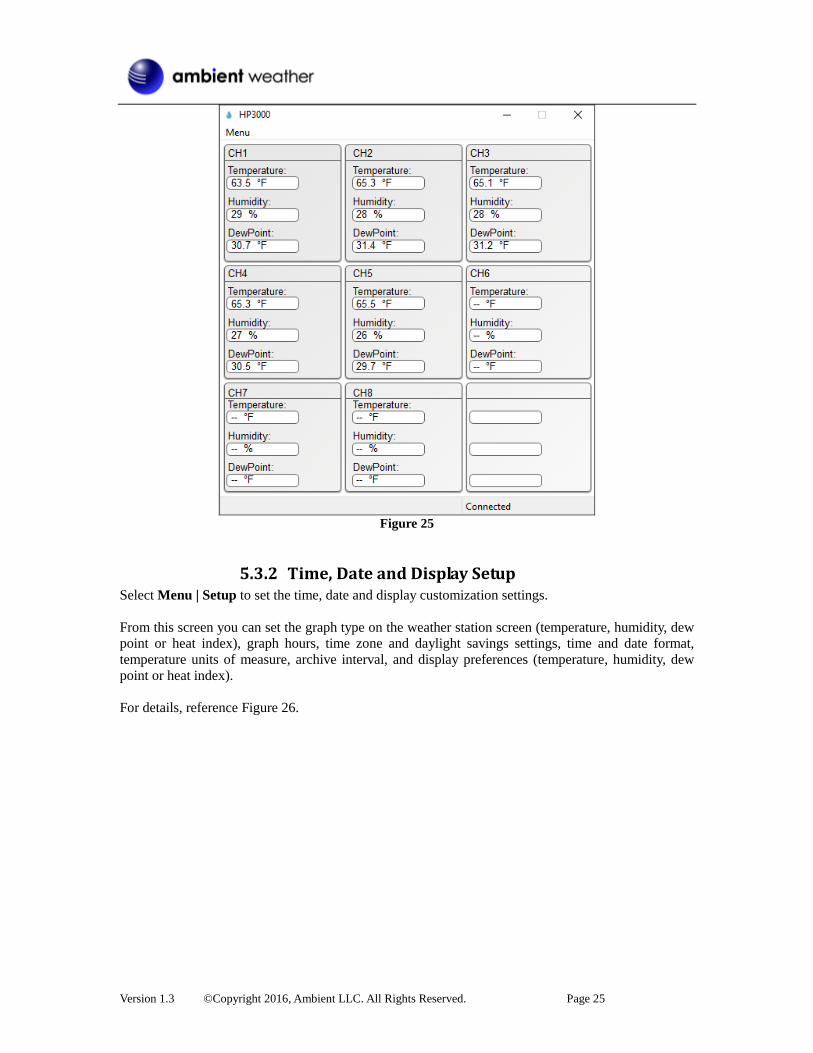
Version 1.3 ©Copyright 2016, Ambient LLC. All Rights Reserved. Page 25
Figure 25
5.3.2 Time, Date and Display Setup Select Menu | Setup to set the time, date and display customization settings.
From this screen you can set the graph type on the weather station screen (temperature, humidity, dew
point or heat index), graph hours, time zone and daylight savings settings, time and date format,
temperature units of measure, archive interval, and display preferences (temperature, humidity, dew
point or heat index).
For details, reference Figure 26.
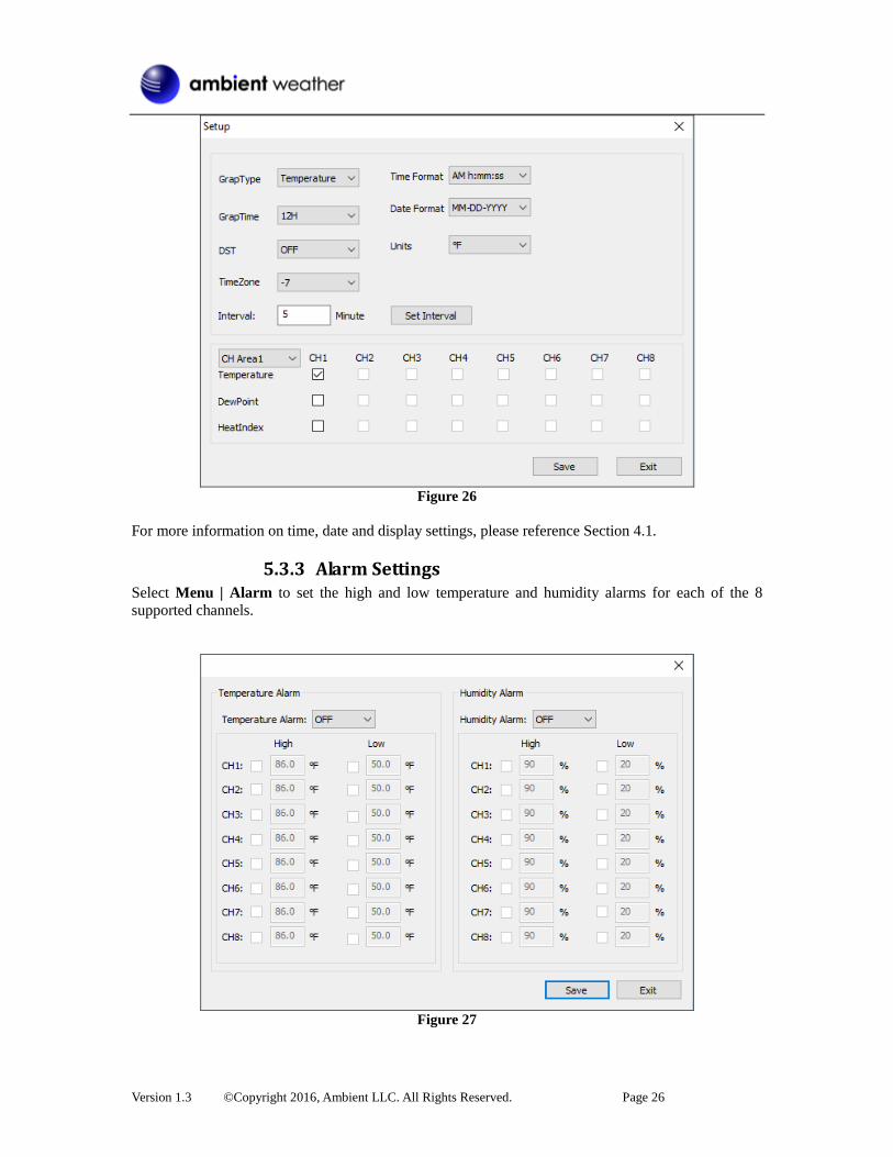
Version 1.3 ©Copyright 2016, Ambient LLC. All Rights Reserved. Page 26
Figure 26
For more information on time, date and display settings, please reference Section 4.1.
5.3.3 Alarm Settings Select Menu | Alarm to set the high and low temperature and humidity alarms for each of the 8
supported channels.
Figure 27

Version 1.3 ©Copyright 2016, Ambient LLC. All Rights Reserved. Page 27
For more information on Alarm Settings, please reference Section 4.3.
5.3.4 Calibration Select Menu | Calibration to calibrate each of the 8 supported channels.
The temperature and humidity values are offsets.
Example: If the actual temperature measured by a calibrated source is 70 °F, and the channel 1
temperature sensor reads 69.5 °F:
CH1 Temperature Offset = 70 – 69.5 = 0.5 °F.
Enter 0.5 in the CH1 Temperature field, as shown in Figure 28.
Figure 28
It may take a minute or two for the console to update the calibrated temperature, since the temperature
updates once per minute.
Note: There may be some °F to °C rounding error, since the native calculations are performed
in °C. For example, if you enter 0.6 °F in the field, 0.5 °F may be displayed the next time you open
this panel.
For more information on Calibration, please reference Section 4.2.
5.3.5 SDCard File
Note: The Micro SD Card is optional, not included and sold separately.

Version 1.3 ©Copyright 2016, Ambient LLC. All Rights Reserved. Page 28
Select Menu | SDCard File to download and analyze data stored on the SD Card.
Select the file you wish to view from the list and press Select to view the data.
To graph the data:
1. Identify the data file start and end date and times (Figure 29).
2. Press the Graph button.
3. Enter the start and end date and times in the appropriate fields identified in Step 1 (Figure 30).
4. Select the parameter you wish to graph, and press the Select button.
Figure 29
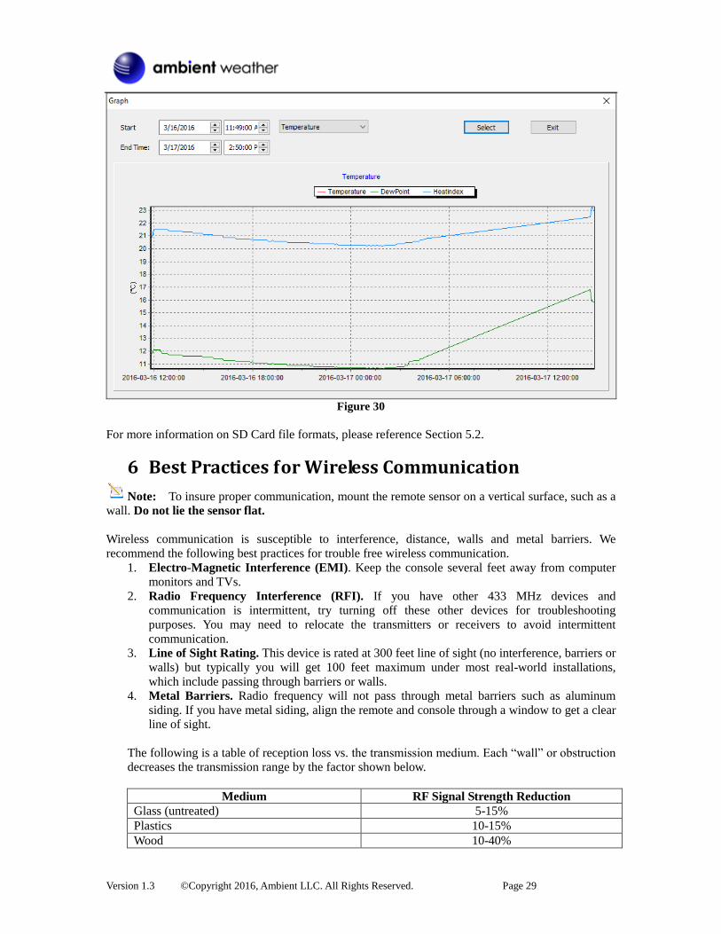
Version 1.3 ©Copyright 2016, Ambient LLC. All Rights Reserved. Page 29
Figure 30
For more information on SD Card file formats, please reference Section 5.2.
6 Best Practices for Wireless Communication
Note: To insure proper communication, mount the remote sensor on a vertical surface, such as a
wall. Do not lie the sensor flat.
Wireless communication is susceptible to interference, distance, walls and metal barriers. We
recommend the following best practices for trouble free wireless communication.
1. Electro-Magnetic Interference (EMI). Keep the console several feet away from computer
monitors and TVs.
2. Radio Frequency Interference (RFI). If you have other 433 MHz devices and
communication is intermittent, try turning off these other devices for troubleshooting
purposes. You may need to relocate the transmitters or receivers to avoid intermittent
communication.
3. Line of Sight Rating. This device is rated at 300 feet line of sight (no interference, barriers or
walls) but typically you will get 100 feet maximum under most real-world installations,
which include passing through barriers or walls.
4. Metal Barriers. Radio frequency will not pass through metal barriers such as aluminum
siding. If you have metal siding, align the remote and console through a window to get a clear
line of sight.
The following is a table of reception loss vs. the transmission medium. Each “wall” or obstruction
decreases the transmission range by the factor shown below.
Medium RF Signal Strength Reduction
Glass (untreated) 5-15%
Plastics 10-15%
Wood 10-40%
Version 1.3 ©Copyright 2016, Ambient LLC. All Rights Reserved. Page 30
Medium RF Signal Strength Reduction
Brick 10-40%
Concrete 40-80%
Metal 90-100%
7 Glossary of Terms
Term Definition
Accuracy Accuracy is defined as the ability of a measurement to match the actual
value of the quantity being measured.
Hygrometer A hygrometer is a device that measures relative humidity. Relative
humidity is a term used to describe the amount or percentage of water
vapor that exists in air.
Range Range is defined as the amount or extent a value can be measured.
8 Accessories Accessory Description
microSDHC Class 4 Flash
Memory Card SDC4/8GB
MicroSDHC for data backup and advanced data analysis.
9 Specifications
9.1 Wireless Specifications Line of sight wireless transmission (in open air): 300 feet, 100 feet under most conditions.
Frequency: 915 MHz
Update Rate: About 60 seconds
9.2 Measurement Specifications The following table provides specifications for the measured parameters.
Measurement Range Accuracy Resolution
Indoor Temperature 32 to 140 °F ± 2 °F 0.1 °F
Outdoor Temperature -40 to 140 °F ± 2 °F 0.1 °F
Indoor Humidity 10 to 99 % ± 5% (only guaranteed
between 20 to 90%)
1 %
Outdoor Humidity 10 to 99% ± 5% (only guaranteed
between 20 to 90%)
1 %
9.3 Power Consumption Base station (display console) : AC Power
Remote sensor : 2 x AA 1.5V Alkaline or Lithium batteries (not included)
Battery life: Minimum 12 months for base station with one sensor and excellent reception.
Intermittent reception and multiple sensors may reduce the battery life.
Minimum 12 months for thermometer-hygrometer sensor (use lithium batteries in cold
weather climates less than -4 °F)
Version 1.3 ©Copyright 2016, Ambient LLC. All Rights Reserved. Page 31
10 Troubleshooting Guide If your question is not answered here, you can contact us as follows:
1. Email Support: [email protected]
2. Technical Support: 480-346-3380 (M-F 8am to 3pm Arizona Time)
Problem Solution
Wireless remote (thermo-hygrometer) not
reporting in to console.
There are dashes (--.-) on the display
console, and these sensors are a port of
your system.
If any of the sensor communication is lost, dashes (--.-)
will be displayed on the screen. To reacquire the signal,
re-acquire the signal per Section 4.4.3. Please verify each
sensor is on a different channel by viewing the sensor’s
LCD display.
The maximum line of sight communication range is 300’
and 100’ under most conditions. Move the sensor
assembly closer to the display console.
If the sensor assembly is too close (less than 5’), move
the sensor assembly away from the display console.
Make sure the remote sensor LCD display is working.
Install a fresh set of batteries in the remote
thermo-hygrometer. For cold weather environments,
install lithium batteries.
Make sure the remote sensors are not transmitting
through solid metal (acts as an RF shield), or earth
barrier (down a hill).
Move the display console around electrical noise
generating devices, such as computers, TVs and other
wireless transmitters or receivers.
Move the remote sensor to a higher location. Move the
remote sensor to a closer location.
Temperature sensor reads too high in the
day time.
Make sure the thermo-hygrometer is mounted in a
shaded area on the north facing wall. Consider the
following radiation shield if this is not possible:
http://www.ambientweather.com/amwesrpatean.html
Temperature sensors do not agree Allow up to one hour for the sensors to stabilize due to
signal filtering. The sensors should agree within 4 °F (the
sensor accuracy is ± 2 °F) under worst case conditions.
Use the calibration feature to match the indoor and
outdoor temperature to a known source.
Humidity sensors do not agree Allow up to one hour for the sensors to stabilize due to
signal filtering. The indoor and outdoor humidity sensors
should agree within 10 % (the sensor accuracy is ± 5 %)
under worst case conditions.
Version 1.3 ©Copyright 2016, Ambient LLC. All Rights Reserved. Page 32
Problem Solution
Use the calibration feature to match the indoor and
outdoor humidity to a known source.
Display console contrast is weak Check the backlight display settings referenced in
Section Back Light.
11 Liability Disclaimer Please help in the preservation of the environment and return used batteries to an authorized depot.
The electrical and electronic wastes contain hazardous substances. Disposal of electronic waste in
wild country and/or in unauthorized grounds strongly damages the environment.
Reading the “User manual” is highly recommended. The manufacturer and supplier cannot accept any
responsibility for any incorrect readings and any consequences that occur should an inaccurate reading
take place.
This product is designed for use in the home only as indication of weather conditions. This product is
not to be used for medical purposes or for public information.
The specifications of this product may change without prior notice.
This product is not a toy. Keep out of the reach of children.
No part of this manual may be reproduced without written authorization of the manufacturer.
Ambient, LLC WILL NOT ASSUME LIABILITY FOR INCIDENTAL, CONSEQUENTIAL,
PUNITIVE, OR OTHER SIMILAR DAMAGES ASSOCIATED WITH THE OPERATION OR
MALFUNCTION OF THIS PRODUCT.
12 FCC Statement Statement according to FCC part 15.19: This device complies with part 15 of the FCC rules. Operation is subject to the following two
conditions:
1. This device may not cause harmful interference.
2. This device must accept any interference received, including interference that may cause
undesired operation.
Statement according to FCC part 15.21: Modifications not expressly approved by this company could void the user's authority to operate the
equipment.
Statement according to FCC part 15.105: NOTE: This equipment has been tested and found to comply with the limits for a Class B digital
device, pursuant to Part 15 of the FCC Rules. These limits are designed to provide reasonable
protection against harmful interference in a residential installation. This equipment generates, uses and
can radiate radio frequency energy and, if not installed and used in accordance with the instructions,
may cause harmful interference to radio communications.
However, there is no guarantee that interference will not occur in a particular installation. If this
equipment does cause harmful interference to radio or television reception, which can be determined
by turning the equipment off and on, the user is encouraged to try to correct the interference by one or more of the following measures:
• Reorient or relocate the receiving antenna.

Version 1.3 ©Copyright 2016, Ambient LLC. All Rights Reserved. Page 33
• Increase the separation between the equipment and receiver.
• Connect the equipment into an outlet on a circuit different from that to which the receiver is
connected.
• Consult the dealer or an experienced radio/TV technician for help.
13 Warranty Information Ambient, LLC provides a 1-year limited warranty on this product against manufacturing defects in
materials and workmanship.
This limited warranty begins on the original date of purchase, is valid only on products purchased and
only to the original purchaser of this product. To receive warranty service, the purchaser must contact
Ambient, LLC for problem determination and service procedures.
Warranty service can only be performed by a Ambient, LLC. The original dated bill of sale must be
presented upon request as proof of purchase to Ambient, LLC.
Your Ambient, LLC warranty covers all defects in material and workmanship with the following
specified exceptions: (1) damage caused by accident, unreasonable use or neglect (lack of reasonable
and necessary maintenance); (2) damage resulting from failure to follow instructions contained in your
owner’s manual; (3) damage resulting from the performance of repairs or alterations by someone other
than an authorized Ambient, LLC authorized service center; (4) units used for other than home use (5)
applications and uses that this product was not intended (6) the products inability to receive a signal
due to any source of interference or metal obstructions and (7) extreme acts of nature, such as
lightning strikes or floods.
This warranty covers only actual defects within the product itself, and does not cover the cost of
installation or removal from a fixed installation, normal set-up or adjustments, claims based on
misrepresentation by the seller or performance variations resulting from installation-related
circumstances.