ceratizit feed-out tools komdrive
TRANSCRIPT
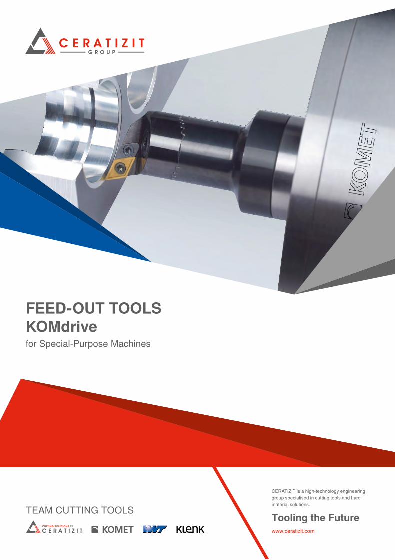
FEED-OUT TOOLS KOMdrivefor Special-Purpose Machines
Tooling the Futurewww.ceratizit.com
CERATIZIT is a high-technology engineering group specialised in cutting tools and hard material solutions.
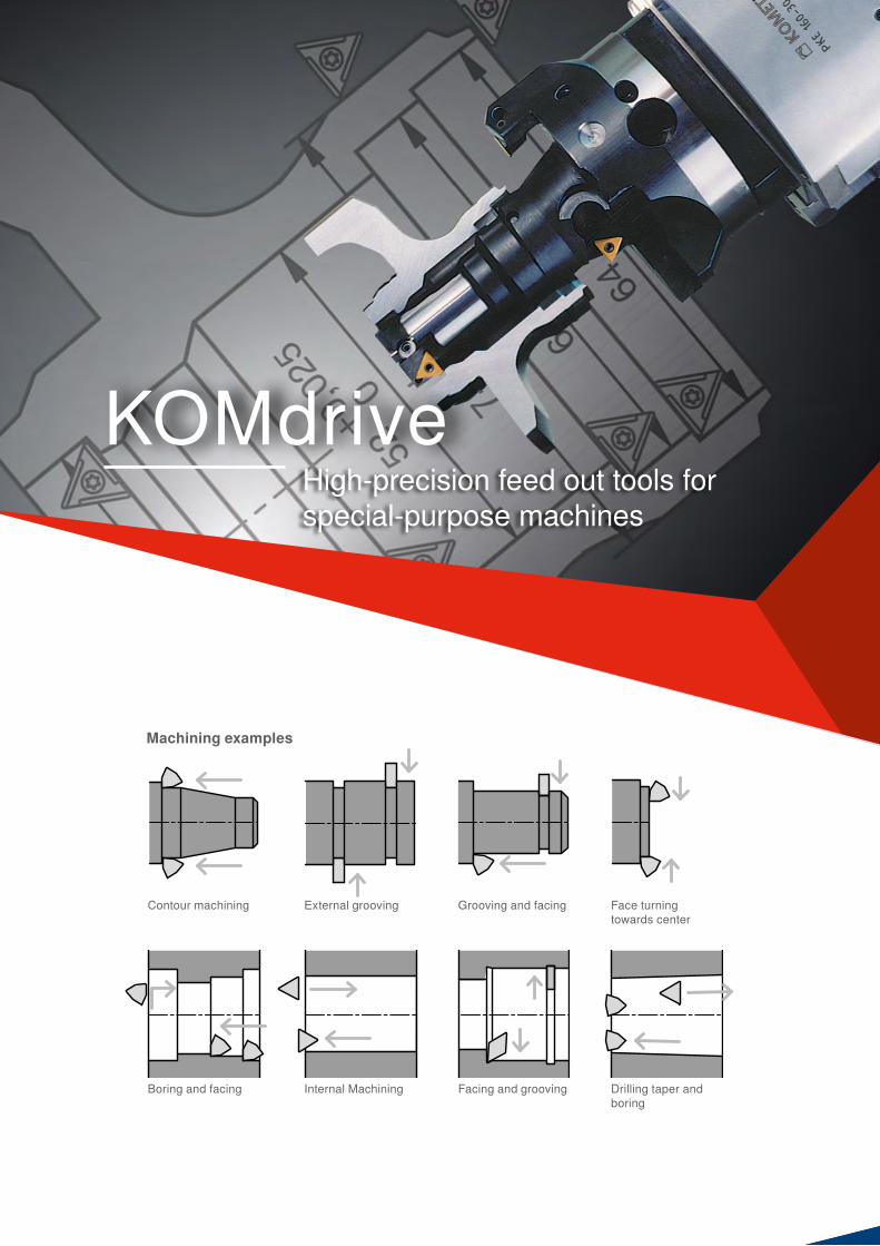
High-precision feed out tools for special-purpose machines
Contour machining External grooving
Facing and grooving
Face turning towards center
Grooving and facing
Boring and facing Drilling taper and boring
Machining examples
Internal Machining
KOMdrive

Your Technical Sales Engineer will be happy to answer any further questions or please contact directly
The slides of the facing heads are actuated mechanically through precision ground serrated rack components designed with maximum engagement of the teeth. The radial stroke is limited through fine adjustable internal stops for safety reasons. Sliding parts are made of long-term nitrided steel with high surface hardness and low friction properties.
▲ Low coefficient of friction through special surface treatment of the sliding components
▲ Minimal backlash in the μm range ▲ Compact slide designs including integrated ABS connections for
highest rigidity and metal removal ▲ High spindle speeds without compromising machining accuracy
or service life ▲ Precision manufacturing processes and extensive research and
development warrant the highest technological level
Unbeatable precision combined with a long service life
4
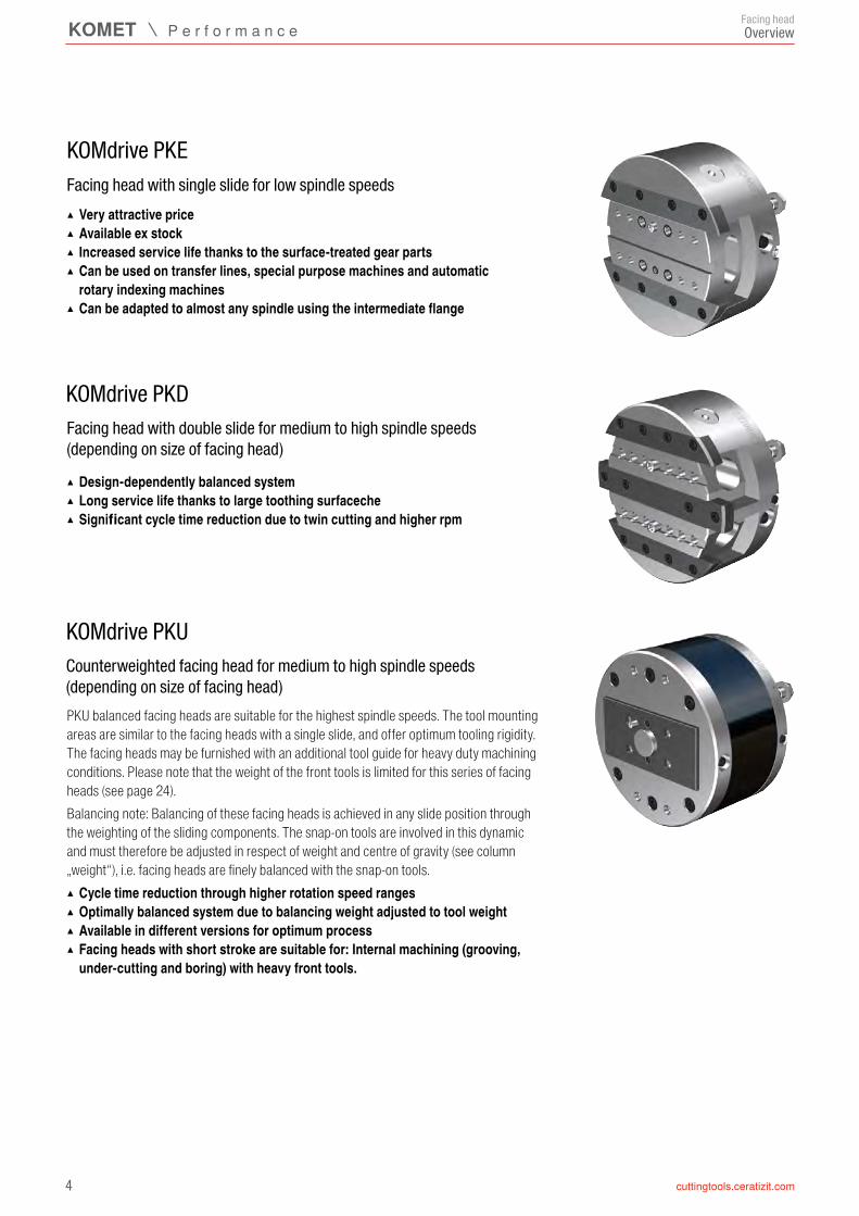
KOMdrive PKD
KOMdrive PKU
KOMdrive PKE
Facing headOverview
▲ Design-dependently balanced system ▲ Long service life thanks to large toothing surfaceche ▲ Significant cycle time reduction due to twin cutting and higher rpm
Facing head with double slide for medium to high spindle speeds (depending on size of facing head)
PKU balanced facing heads are suitable for the highest spindle speeds. The tool mounting areas are similar to the facing heads with a single slide, and offer optimum tooling rigidity. The facing heads may be furnished with an additional tool guide for heavy duty machining conditions. Please note that the weight of the front tools is limited for this series of facing heads (see page 24).Balancing note: Balancing of these facing heads is achieved in any slide position through the weighting of the sliding components. The snap-on tools are involved in this dynamic and must therefore be adjusted in respect of weight and centre of gravity (see column „weight“), i.e. facing heads are finely balanced with the snap-on tools.
▲ Cycle time reduction through higher rotation speed ranges ▲ Optimally balanced system due to balancing weight adjusted to tool weight ▲ Available in different versions for optimum process ▲ Facing heads with short stroke are suitable for: Internal machining (grooving, under-cutting and boring) with heavy front tools.
Counterweighted facing head for medium to high spindle speeds (depending on size of facing head)
▲ Very attractive price ▲ Available ex stock ▲ Increased service life thanks to the surface-treated gear parts ▲ Can be used on transfer lines, special purpose machines and automatic rotary indexing machines
▲ Can be adapted to almost any spindle using the intermediate flange
Facing head with single slide for low spindle speeds

5
16 – 19
6 – 15
32
6 – 7 8 – 9
10 – 11 12 – 13
1415
20 – 24
34 – 35
28 – 31
26 – 27
16 – 17 1819
20 – 21 22 – 23
24
33
25neu Montagevarianten
Facing headIndex
KOMdrive PKD
KOMdrive PKE
Modified facing heads
PKE-101 Facing head with single slide with mounting holes in slidePKE-101 Facing head with single slide with mounting holes in slide with internal coolant supplyPKE-103 Facing head with single slide with integrated ABS-N connectionPKE-104 Facing head with single slide with integrated SBA connectionAdaptor with ABS-N connectionTechnical notes
KOMdrive PKU
KOMlife – Autonomous acquisition of production data accurate to the second
Machining examples
Assembly variants
PKD-101 Facing head with double slide with mounting holes in slideAdaptor with ABS-N connectionTechnical notes
PKU-101 Facing head with counterweighted with mounting holes in slidePKU-103 Facing head with counterweighted with integrated ABS-N connectionTechnical notes
KOMtronic U-axis systems for special purpose machines
Index
KOMdrive Adaptor flange

6
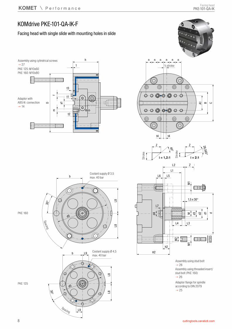
KOMdrive PKE-101 / PKE-101-QA
PKE-101 / PKE-101-QA
D a1
fm
A1 B C
t2
h
t1
n n n n n n
1
L6
Z 40°
Z 26,565°
i = 1,2:1 i = 2:1
M d3 d2 d1 d
M1
h2H2
ZL2
L1L5
d4
L7
L4 L3
b
30°
d5
t3
Facing head
Facing head with single slide with mounting holes in slide
stroke
Spacing
½ stroke
strok
e
strok
e
Adaptor flange for spindle according to DIN 2079 → 25
Assembly using stud bolt→ 26
Adaptor with ABS-N connection→ 14

7
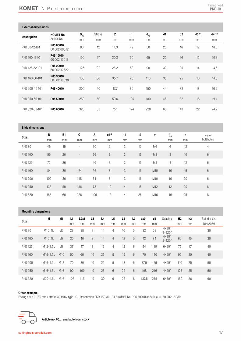
Dh6 i Z h dh6 d1 d2 d3H7 d4+0,1
PKE 80-12-101 P01 00010 80 12 1,2 : 1 14,3 42 50 25 16 12 10,3
PKE 100-17-101 QA P01 1001160 000 10017
10017 1,2 : 1 40°
20,3 50 65 25 16 12 10,3PKE 100-10-101 QA 2:1 P01 10016
60 000 10010 10 2 : 1 26,565°
PKE 125-22-101 QA P01 2001160 000 12522
12522 1,2 : 1 40°
26,2 58 90 30 20 14 14,6PKE 125-13-101 QA 2:1 P01 20016
60 000 12513 13 2 : 1 26,565°
PKE 160-30-101 QA P01 3001160 000 16030
16030 1,2 : 1 40°
35,7 70 110 35 25 18 14,6PKE 160-18-101 QA 2:1 P01 30016
60 000 16018 18 2 : 1 26,565°
PKE 200-40-101 QA P01 40011200
40 1,2 : 1 40°47,7 85 150 44 32 18 16,2
PKE 200-24-101 QA P01 40016 24 2 : 1 26,565°
PKE 250-50-101 QA P01 50011250
50 1,2 : 1 40°59,6 100 180 46 32 18 19,4
PKE 250-30-101 QA P01 50016 30 2 : 1 26,565°
B C A1 a1H8 t1 t2 m f m6 n
PKE 80 36 – 22 8 3 10 M6 6 12 8
PKE 100 40 72 26 8 3 10 M6 6 11 12
PKE 125 50 86 32 10 4 12 M8 8 13 12
PKE 160 60 100 40 10 4 12 M8 8 16 12
PKE 200 80 130 55 12 4 15 M10 10 20 12
PKE 250 100 150 70 12 4 18 M12 12 20 16
M M1 L1 L2±1 L3 L4 L5 L6 L7 b±0,1 d5 H2 h2
PKE 80 M10×1L M6 28 38 8 14 4 10 5 32 68 4×90°3×120° 60 18 30
PKE 100 M10×1L M8 30 40 8 14 4 12 5 42 84 4×90°3×120° 65 15 30
PKE 125 M12×1,5L M8 37 47 8 16 4 12 6 54 110 6×60° 75 17 40
PKE 160 M16×1,5L M10 50 60 10 25 5 15 6 70 140 4×90° 90 20 40
PKE 200 M16×1,5L M12 70 80 10 25 5 18 6 87,5 175 4×90° 110 25 50
PKE 250 M16×1,5L M16 90 100 10 25 6 22 6 108 216 4×90° 125 25 50
PKE-101 / PKE-101-QAFacing head
External dimensions
Description KOMET No.Article No.
Strokemm mm Traduction Pitch mm mm mm mm mm mm mm
Order example: Facing head Ø 100 mm / stroke 17 mm / type 101 QA: Description PKE100-17-101QA / KOMET No. P01 10011 or Article-Nr. 60 000 10017
PKE size 320 / 400 / 500 on request.
Slide dimensions
Size No. of bolt holesmm mm mm mm mm mm mm mm
Mounting dimensions
SizeSpacing Spindle size
mm mm mm mm mm mm mm mm mm mm mm DIN 2079
Article no. 60.... available from stock
8
KOMdrive PKE-101-QA-IK-F
PKE-101-QA-IK
D a1
fm
A1 B C
t2
h
t1
n n n n n n
1
L6
Z 40°
Z 26,565°
i = 1,2:1 i = 2:1
M d3 d2 d1 d
M1M1h2
H2
ZL2
L1L5
d4
L7
L4 L3
b
30° 1,5 x 30°
d5
L8L8
b
30°
d5
L8L8
t3
t4 t4
M2
L9
L9
PKE 160
PKE 125
PKE 125: M10x60 PKE 160: M10x80
Facing head
Facing head with single slide with mounting holes in slide
Spacing
½ stroke
Stro
ke
Stro
ke
Adaptor flange for spindle according to DIN 2079 → 25
Adaptor with ABS-N connection→ 14
Assembly using stud bolt→ 26
Assembly using cylindrical screws → 27
Assembly using threaded insert/stud bolt (PKE 160)→ 26
Coolant supply Ø 3,5max. 40 bar
Spacing
Coolant supply Ø 4,5max. 40 bar

9
Dh6 i Z h dh6 d1 d2 d3H7 d4+0,1
PKE 125-22-101 QA.IK.F 1P01 000100099X60 001 12522
12522 1,2 : 1 40°
26,2 58 90 30 20 14 14,6PKE 125-13-101 QA.IK.F 1P01 000100101X
60 001 12513 13 2 : 1 26,565°
PKE 160-30-101 QA.IK.F 1P01 000100100X60 001 16030
16030 1,2 : 1 40°
35,7 70 110 35 25 18 14,6PKE 160-18-101 QA.IK.F 1P01 000100103X
60 001 16018 18 2 : 1 26,565°
B C A1 a1H8 t1 t2 t3 t4 m f m6 n
PKE 125 50 86 32 10 4 12 5 6,5 M8 8 13 12
PKE 160 60 100 40 10 4 12 5 7 M8 8 16 12
M M1 M2 L1 L2±1 L3 L4 L5 L6 L7 L8 L9 b±0,1 d5 H2 h2
PKE 125 M12×1,5L M8 – 37 47 8 16 4 12 6 47 17 54 110 6×60° 75 17 40
PKE 160 M16×1,5L M10 M14×1,5 50 60 10 25 5 15 6 68 – 70 140 4×90° 90 20 40
PKE-101-QA-IKFacing head
External dimensions
Description KOMET No.Article No.
Strokemm mm Traduction Pitch mm mm mm mm mm mm mm
Order example: Facing head Ø 125 mm / stroke 22 mm / type 101 QA-IK: Description PKE 125-22-101 QA.IK.F / KOMET No. 1P01 000100099X or Article-Nr. 60 001 12522
Slide dimensions
Size No. of bolt holesmm mm mm mm mm mm mm mm mm mm
Article no. 60.... available from stock
Mounting dimensions
SizeSpacing Spindle size
mm mm mm mm mm mm mm mm mm mm mm mm mm DIN 2079

10
KOMdrive PKE-103 / PKE-103-QA
PKE-103 / PKE-103-QA
D B C
h3
1
L6
Z 40°
Z 26,565°
i = 1,2:1 i = 2:1
M d3 d2 d1 d
M1
h2H2
ZL2
L1L5
d4
L7
L4 L3
b
30°
d5
hAB
S-N
d
Facing head
Facing head with single slide with integrated ABS-N connectionon request
stroke
Spacing
½ stroke
strok
e
strok
e
Adaptor flange for spindle according to DIN 2079 → 25
Assembly using stud bolt→ 26

11
Dh6 i Z h h3 dh6 d1 d2 d3H7 d4+0,1
PKE 80-6-103 P01 00030 80 6 1,2 : 1 7,2 52 42 50 25 16 12 10,3
PKE 100-10-103 QA P01 10031100
10 1,2 : 1 40°11,9 60 50 65 25 16 12 10,3
PKE 100-6-103 QA P01 10036 6 2 : 1 26,565°
PKE 125-12-103 QA P01 20031125
12 1,2 : 1 40°14,3 68 58 90 30 20 14 14,6
PKE 125-7-103 QA P01 20036 7 2 : 1 26,565°
PKE 160-15-103 QA P01 30031160
15 1,2 : 1 40°17,9 85 70 110 35 25 18 14,6
PKE 160-9-103 QA P01 30036 9 2 : 1 26,565°
PKE 200-20-103 QA P01 40031200
20 1,2 : 1 40°23,8 100 85 150 44 32 18 16,2
PKE 200-12-103 QA P01 40036 12 2 : 1 26,565°
PKE 250-30-103 P01 50030 250 30 2 : 1 35,7 120 100 180 46 32 18 19,4
B C dABS-N
PKE 80 36 – 32
PKE 100 40 72 32
PKE 125 50 86 40
PKE 160 60 100 50
PKE 200 80 130 63
PKE 250 100 150 80
M M1 L1 L2±1 L3 L4 L5 L6 L7 b±0,1 d5 H2 h2
PKE 80 M10×1L M6 28 38 8 14 4 10 5 32 68 4×90°3×120° 70 18 30
PKE 100 M10×1L M8 30 40 8 14 4 12 5 42 84 4×90°3×120° 75 15 30
PKE 125 M12×1,5L M8 37 47 8 16 4 12 6 54 110 6×60° 85 17 40
PKE 160 M16×1,5L M10 50 60 10 25 5 15 6 70 140 4×90° 105 20 40
PKE 200 M16×1,5L M12 70 80 10 25 5 18 6 87,5 175 4×90° 125 25 50
PKE 250 M16×1,5L M16 90 100 10 25 6 22 6 108 216 4×90° 145 25 50
PKE-103 / PKE-103-QAFacing head
External dimensions
Description KOMET No.Stroke
mm mm Traduction Pitch mm mm mm mm mm mm mm mm
Order example: Facing head Ø 250 mm / stroke 30 mm / type 103: Description PKE250-30-103 / KOMET No. P01 50030
Slide dimensions
Sizemm mm
Mounting dimensions
SizeSpacing Spindle size
mm mm mm mm mm mm mm mm mm mm mm DIN 2079
D B C
h
1
L6
Z 40°
Z 26,565°
i = 1,2:1 i = 2:1
M d3 d2 d1 d
M1
h2H2
ZL2
L1L5
d4
L7
L4 L3
b
30°
d5
SBA d
D1
12
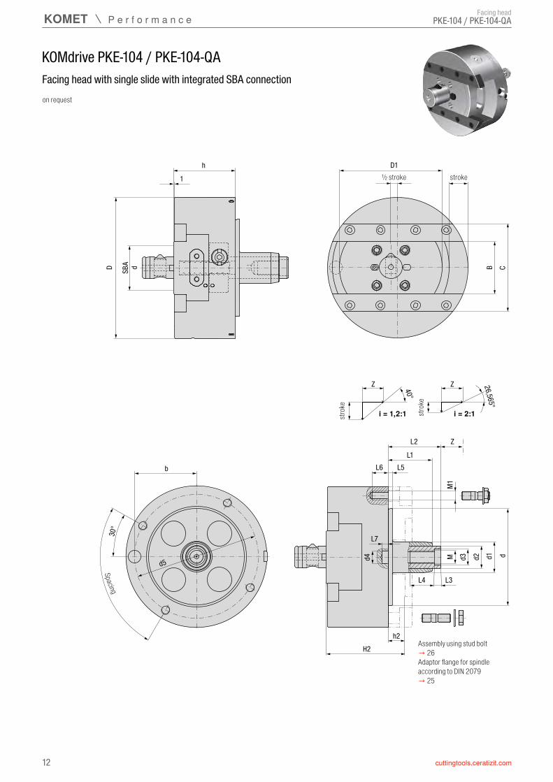
KOMdrive PKE-104 / PKE-104-QA
PKE-104 / PKE-104-QAFacing head
Facing head with single slide with integrated SBA connectionon request
stroke
Spacing
½ stroke
strok
e
strok
e
Adaptor flange for spindle according to DIN 2079 → 25
Assembly using stud bolt→ 26
13
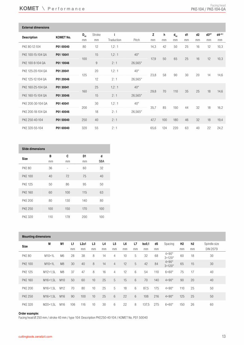
Dh6 i Z h dh6 d1 d2 d3H7 d4+0,1
PKE 80-12-104 P01 00040 80 12 1,2 : 1 14,3 42 50 25 16 12 10,3
PKE 100-15-104 QA P01 10041100
15 1,2 : 1 40°17,9 50 65 25 16 12 10,3
PKE 100-9-104 QA P01 10046 9 2 : 1 26,565°
PKE 125-20-104 QA P01 20041125
20 1,2 : 1 40°23,8 58 90 30 20 14 14,6
PKE 125-12-104 QA P01 20046 12 2 : 1 26,565°
PKE 160-25-104 QA P01 30041160
25 1,2 : 1 40°29,8 70 110 35 25 18 14,6
PKE 160-15-104 QA P01 30046 15 2 : 1 26,565°
PKE 200-30-104 QA P01 40041200
30 1,2 : 1 40°35,7 85 150 44 32 18 16,2
PKE 200-18-104 QA P01 40046 18 2 : 1 26,565°
PKE 250-40-104 P01 50040 250 40 2 : 1 47,7 100 180 46 32 18 19,4
PKE 320-55-104 P01 60040 320 55 2 : 1 65,6 124 220 63 40 22 24,2
B C D1 dSBA
PKE 80 36 – 60 32
PKE 100 40 72 75 40
PKE 125 50 86 95 50
PKE 160 60 100 115 63
PKE 200 80 130 140 80
PKE 250 100 150 170 100
PKE 320 110 178 200 100
M M1 L1 L2±1 L3 L4 L5 L6 L7 b±0,1 d5 H2 h2
PKE 80 M10×1L M6 28 38 8 14 4 10 5 32 68 4×90°3×120° 60 18 30
PKE 100 M10×1L M8 30 40 8 14 4 12 5 42 84 4×90°3×120° 65 15 30
PKE 125 M12×1,5L M8 37 47 8 16 4 12 6 54 110 6×60° 75 17 40
PKE 160 M16×1,5L M10 50 60 10 25 5 15 6 70 140 4×90° 90 20 40
PKE 200 M16×1,5L M12 70 80 10 25 5 18 6 87,5 175 4×90° 110 25 50
PKE 250 M16×1,5L M16 90 100 10 25 6 22 6 108 216 4×90° 125 25 50
PKE 320 M20×1,5L M16 106 116 10 30 6 22 8 137,5 275 6×60° 150 26 60
PKE-104 / PKE-104-QAFacing head
External dimensions
Description KOMET No.Stroke
mm mm Traduction Pitch mm mm mm mm mm mm mm
Order example: Facing head Ø 250 mm / stroke 40 mm / type 104: Description PKE250-40-104 / KOMET No. P01 50040
Slide dimensions
Sizemm mm mm
Mounting dimensions
SizeSpacing Spindle size
mm mm mm mm mm mm mm mm mm mm mm DIN 2079
d H u hABS-N
PKE 80-...-101 P80 03010 32 25 15 42
PKE100-...-101 P80 13010 32 25 15 50
PKE125-...-101 P80 24010 40 30 17 58
PKE160-...-101 P80 35010 50 35 22 70
PKE200-...-101 P80 46010 63 40 24 85
PKE250-...-101 P80 57010 80 45 25 100
PKE320-...-101 P80 68010 100 60 40 124
14
KOMdrive PKE-101 / PKE-101-QA
PKE-101 / PKE-101-QA
ABS-
Nd
hHu
½ Stroke
ABS-N Adaptor
Size KOMET No.mm mm mm
Adaptor
Adaptor with ABS-N connectionwithout internal coolant supply

15
PKE-... / PKE-...-QA
KOMdrive PKE-... / PKE-...-QA
8000 N1760 pound force
7000 N1540 pound force
6000 N1320 pound force
5000 N1100 pound force
4000 N880 pound force
3000 N660 pound force
2000 N440 pound force
1000 N220 pound force
0 500 1000 1500 2000
5
4
3
21
1 PKE100 1,2 kg 2.6 lbs
2 PKE125 2,0 kg 4.4 lbs
3 PKE160 3,2 kg 7.1 lbs
4 PKE200 5,5 kg 12.1 lbs
5 PKE250 12,0 kg 26.5 lbs
0 2 4 6 8 10 12
36003400320030002800260024002200200018001600140012001000
800
PKE100 PKE125 PKE160 PKE200 PKE250
70 ml4.3 in³
60 ml3.7 in³
50 ml3.1 in³
40 ml2.4 in³
30 ml1.8 in³
20 ml1.2 in³
10 ml0.6 in³
r.p.m. max =2500
√ stroke*
** Spindle speed [rpm]Drawbar forces shown are valid for maximum weight of front tool.
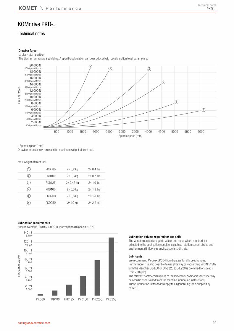
Lubrication volume required for one shiftThe values specified are guide values and must, where required, be adjusted to the application conditions such as rotation speed, stroke and environmental influences such as coolant, dirt, etc.
LubricantsWe recommend Mobilux EP004 liquid grease for all speed ranges. Furthermore, it is also possible to use slideway oils according to DIN 51502 with the identifier CG-L68 or CG-L220 (CG-L220 is preferred for speeds from 700 rpm).The relevant commercial names of the mineral oil companies for slide-way oils can be ascertained from the machine lubrication instructions.These lubrication instructions apply to all generating tools supplied by KOMET.
The maximum spindle speed is estimated as follows:
* stroke in mm from /to rotational axis
Lubr
icatio
n volu
me
***max. weight of front tool
Technical notes
Spind
le sp
eed [
rpm]
+/– stroke [mm]
***max. weight of front toolStroke/spindle speed diagram
Technical notes
Draw
bar f
orce
**Spindle speed [rpm]
Slide movement: 150 m / 6,000 in. (corresponds to one shift, 8 h)Lubrication requirements
Full max. strokeThe diagram serves as a guideline. A specific calculation can be produced with consideration to all parameters.
Drawbar force

16
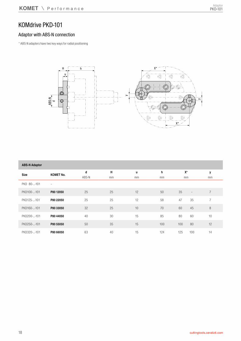
KOMdrive PKD-101
PKD-101
D
a1f
m
B C
t2
h
t1
n n n n n n
n n n n n n
1
L6
Z 40°
M d3 d2 d1 d
M1
h2H2
ZL2
L1L5
d4
L7
L4 L3
b
30°
d5
t3
B1
Facing head
Facing head with double slide with mounting holes in slides
Stroke ½ Stroke
Adaptor with ABS-N connection→ 18
Spacing
Stroke½ Stroke
Stro
ke
Adaptor flange for spindle according to DIN 2079 → 25
Assembly using stud bolt→ 26
17
Dh6 Z h dh6 d1 d2 d3H7 d4+0,1
PKD 80-12-101 P05 0001060 002 08012 80 12 14,3 42 50 25 16 12 10,3
PKD 100-17-101 P05 1001060 002 10017 100 17 20,3 50 65 25 16 12 10,3
PKD 125-22-101 P05 2001060 002 12522 125 22 26,2 58 90 30 20 14 14,6
PKD 160-30-101 P05 3001060 002 16030 160 30 35,7 70 110 35 25 18 14,6
PKD 200-40-101 P05 40010 200 40 47,7 85 150 44 32 18 16,2
PKD 250-50-101 P05 50010 250 50 59,6 100 180 46 32 18 19,4
PKD 320-63-101 P05 60010 320 63 75,1 124 220 63 40 22 24,2
B B1 C A a1H8 t1 t2 m f m6 n
PKD 80 46 15 – 30 6 3 10 M6 6 12 4
PKD 100 56 20 – 36 8 3 15 M8 8 10 6
PKD 125 72 26 – 46 8 3 15 M8 8 12 6
PKD 160 84 30 124 56 8 3 16 M10 10 15 6
PKD 200 102 36 148 64 8 3 16 M10 10 20 6
PKD 250 136 50 186 78 10 4 18 M12 12 20 8
PKD 320 166 60 226 106 12 4 25 M16 16 25 8
M M1 L1 L2±1 L3 L4 L5 L6 L7 b±0,1 d5 H2 h2
PKD 80 M10×1L M6 28 38 8 14 4 10 5 32 68 4×90°3×120° – – 30
PKD 100 M10×1L M8 30 40 8 14 4 12 5 42 84 4×90°3×120° 65 15 30
PKD 125 M12×1,5L M8 37 47 8 16 4 12 6 54 110 6×60° 75 17 40
PKD 160 M16×1,5L M10 50 60 10 25 5 15 6 70 140 4×90° 90 20 40
PKD 200 M16×1,5L M12 70 80 10 25 5 18 6 87,5 175 4×90° 110 25 50
PKD 250 M16×1,5L M16 90 100 10 25 6 22 6 108 216 4×90° 125 25 50
PKD 320 M20×1,5L M16 106 116 10 30 6 22 8 137,5 275 6×60° 150 26 60
PKD-101 Facing head
External dimensions
Description KOMET No.Article No.
Strokemm mm mm mm mm mm mm mm mm
Order example: Facing head Ø 160 mm / stroke 30 mm / type 101: Description PKD 160-30-101 / KOMET No. P05 30010 or Article-Nr. 60 002 16030
Slide dimensions
Size No. of bolt holesmm mm mm mm mm mm mm mm mm
Mounting dimensions
SizeSpacing Spindle size
mm mm mm mm mm mm mm mm mm mm mm DIN 2079
Article no. 60.... available from stock
ABS-
Nd
hHu
X*
X*
y
y
d H u h X* yABS-N
PKD 80-...-101 –
PKD100-...-101 P80 12050 25 25 12 50 35 – 7
PKD125-...-101 P80 22050 25 25 12 58 47 35 7
PKD160-...-101 P80 33050 32 25 10 70 60 45 8
PKD200-...-101 P80 44050 40 30 15 85 80 60 10
PKD250-...-101 P80 55050 50 35 15 100 100 80 12
PKD320-...-101 P80 66050 63 40 15 124 125 100 14
18
KOMdrive PKD-101
PKD-101
ABS-N Adaptor
Size KOMET No.mm mm mm mm mm
Adaptor
Adaptor with ABS-N connection* ABS-N adapters have two key ways for radial positioning
19
PKD-...
KOMdrive PKD-...
1 PKD 80 2× 0,2 kg 2× 0.4 lbs
2 PKD100 2× 0,3 kg 2× 0.7 lbs
3 PKD125 2× 0,45 kg 2× 1.0 lbs
4 PKD160 2× 0,6 kg 2× 1.3 lbs
5 PKD200 2× 0,8 kg 2× 1.8 lbs
6 PKD250 2×1,0 kg 2× 2.2 lbs
500 1000 1500 2000 2500 3000 3500 4000 4500 5000 5500 6000
65 4
3
2
1
20 000 N4500 pound force
18 000 N4100 pound force
16 000 N3600 pound force
14 000 N3200 pound force
12 000 N2700 pound force
10 000 N2300 pound force
8 000 N1800 pound force
6 000 N1400 pound force
4 000 N900 pound force
2 000 N450 pound force
PKD80 PKD100 PKD125 PKD160 PKD200 PKD250
140 ml8.5 in³
120 ml7.3 in³
100 ml6.1 in³
80 ml4.9 in³
60 ml3.7 in³
40 ml2.4 in³
20 ml1.2 in³
* Spindle speed [rpm]Drawbar forces shown are valid for maximum weight of front tool.
Lubr
icatio
n volu
me
max. weight of front tool
Technical notes
Technical notes
Draw
bar f
orce
*Spindle speed [rpm]
Slide movement: 150 m / 6,000 in. (corresponds to one shift, 8 h)Lubrication requirements
Lubrication volume required for one shiftThe values specified are guide values and must, where required, be adjusted to the application conditions such as rotation speed, stroke and environmental influences such as coolant, dirt, etc.
LubricantsWe recommend Mobilux EP004 liquid grease for all speed ranges. Furthermore, it is also possible to use slideway oils according to DIN 51502 with the identifier CG-L68 or CG-L220 (CG-L220 is preferred for speeds from 700 rpm).The relevant commercial names of the mineral oil companies for slide-way oils can be ascertained from the machine lubrication instructions.These lubrication instructions apply to all generating tools supplied by KOMET.
stroke = start positionThe diagram serves as a guideline. A specific calculation can be produced with consideration to all parameters.
Drawbar force
D d6
fm
Ax B
t2
h
t1
ay4
L6
Z 40°
M d3 d2 d1 d
M1
h2H2
ZL2
L1L5
d4
L7
L4 L3
b
30°
d5
ax
AyL
20
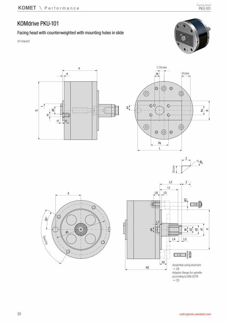
KOMdrive PKU-101
PKU-101
Stro
ke
Spacing
Stroke
½ Stroke
Facing head
Facing head with counterweighted with mounting holes in slideon request
Adaptor flange for spindle according to DIN 2079 → 25
Assembly using stud bolt→ 26

Dh6 Z h dh6 d1 d2 d3H7 d4+0,1
PKU 100-10-101 P20 10110 100 10 11,9 66 65 25 16 12 10,3
PKU 125-6-101 P20 20010125
6 7,273 90 30 20 14 14,6
PKU 125-15-101 P20 20110 15 17,9
PKU 160-8-101 P20 30010160
8 9,595 110 35 25 18 14,6
PKU 160-22-101 P20 30110 22 26,2
PKU 200-10-101 P20 40010200
10 11,9115 150 44 32 18 16,2
PKU 200-30-101 P20 40110 30 35,7
PKU 250-12-101 P20 50010250
12 14,3140 180 46 32 18 19,4
PKU 250-40-101 P20 50110 40 47,7
PKU 320-15-101 P20 60010320
15 17,9174 220 63 40 22 24,2
PKU 320-50-101 P20 60110 50 59,6
M M1 L1 L2±1 L3 L4 L5 L6 L7 b±0,1 d5 H2 h2
PKU 100 M10×1L M8 30 40 8 14 4 12 5 42 84 4×90°3×120° 81 15 30
PKU 125 M12×1,5L M8 37 47 8 16 4 12 6 54 110 6×60° 90 17 40
PKU 160 M16×1,5L M10 50 60 10 25 5 15 6 70 140 4×90° 115 20 40
PKU 200 M16×1,5L M12 70 80 10 25 5 18 6 87,5 175 4×90° 140 25 50
PKU 250 M16×1,5L M16 90 100 10 25 6 22 6 108 216 4×90° 165 25 50
PKU 320 M20×1,5L M16 106 116 10 30 6 22 8 137,5 275 6×60° 200 26 60
B L Ax Ay ax±0,02 ay±0,02 d6h6 t1 t2 m f m6 kg lbs
PKU 100-10-101 42 80 18 33 11 7 16 5 9 M6 5 0,22 – 0,4 0.5 – 0.9
PKU 125-6-101 52 88 28 50 14 15 20 5 16 M8 6 0,55 – 1,05 1.2 – 2.3
PKU 125-15-101 46 92 22 42 11 12 20 5 13 M6 5 0,53 – 0,9 1.2 – 2.0
PKU 160-8-101 66 106 32 60 16 18 25 5 19 M10 6 0,46 – 1,5 1.0 – 3.3
PKU 160-22-101 56 120 28 50 14 15 25 5 16 M8 6 0,47 – 1,2 1.0 – 2.6
PKU 200-10-101 78 130 40 80 20 25 30 5 18 M12 8 1,25 – 3,5 2.8 – 7.7
PKU 200-30-101 68 150 32 60 16 18 30 5 18 M10 6 1,15 – 2,7 2.5 – 6.0
PKU 250-12-101 93 156 50 90 25 30 32 5 18 M12 10 1,51 – 5,3 3.3 – 11.7
PKU 250-40-101 78 190 40 80 20 25 32 5 18 M12 8 1,23 – 3,8 2.7 – 6.0
PKU 320-15-101 108 194 60 120 30 40 40 5 28 M16 12 0 – 7,2 0 – 15.9
PKU 320-50-101 92 234 50 90 25 30 40 5 22 M12 10 0 – 5,4 0 – 11.9
21
PKU-101
External dimensions
Description KOMET No.Stroke
mm mm mm mm mm mm mm mm mm
Order example: Facing head Ø 250 mm / stroke 40 mm / type 101: Description PKU 250-40-101 / KOMET No. P20 50110
Mounting dimensions
SizeSpacing Spindle size
mm mm mm mm mm mm mm mm mm mm mm DIN 2079
Slide dimensions Front tool
Sizemm mm mm mm mm mm mm mm mm mm min – max min – max
Facing head
D
ABS-
Nd
hH
4
L6
Z 40°
M d3 d2 d1 d
M1
h2H2
ZL2
L1L5
d4
L7
L4 L3
b
30°
d5
D1
u
22
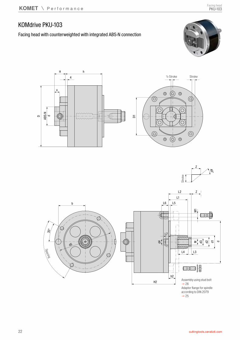
KOMdrive PKU-103
PKU-103
Stro
ke
Spacing
Stroke½ Stroke
Facing head
Facing head with counterweighted with integrated ABS-N connection
Adaptor flange for spindle according to DIN 2079 → 25
Assembly using stud bolt→ 26
Dh6 Z h D1 dh6 d1 d2 d3H7 d4+0,1
PKU 100-10-103 P20 10130 100 10 11,9 61 64 65 25 16 12 10,3
PKU 125-6-103 P20 20030125
6 7,273 85 90 30 20 14 14,6
PKU 125-15-103 P20 20130 15 17,9
PKU 160-8-103 P20 30030160
8 9,595 100 110 35 25 18 14,6
PKU 160-22-103 P20 30130 22 26,2
PKU 200-10-103 P20 40030200
10 11,9115 125 150 44 32 18 16,2
PKU 200-30-103 P20 40130 30 35,7
PKU 250-12-103 P20 50030250
12 14,3140 150 180 46 32 18 19,4
PKU 250-40-103 P20 50130 40 47,7
PKU 320-15-103 P20 60030320
15 17,9174 180 220 63 40 22 24,2
PKU 320-50-103 P20 60130 50 59,6
M M1 L1 L2±1 L3 L4 L5 L6 L7 b±0,1 d5 H2 h2
PKU 100 M10×1L M8 30 40 8 14 4 12 5 42 84 4×90°3×120° 81 15 30
PKU 125 M12×1,5L M8 37 47 8 16 4 12 6 54 110 6×60° 90 17 40
PKU 160 M16×1,5L M10 50 60 10 25 5 15 6 70 140 4×90° 115 20 40
PKU 200 M16×1,5L M12 70 80 10 25 5 18 6 87,5 175 4×90° 140 25 50
PKU 250 M16×1,5L M16 90 100 10 25 6 22 6 108 216 4×90° 165 25 50
PKU 320 M20×1,5L M16 106 116 10 30 6 22 8 137,5 275 6×60° 200 26 60
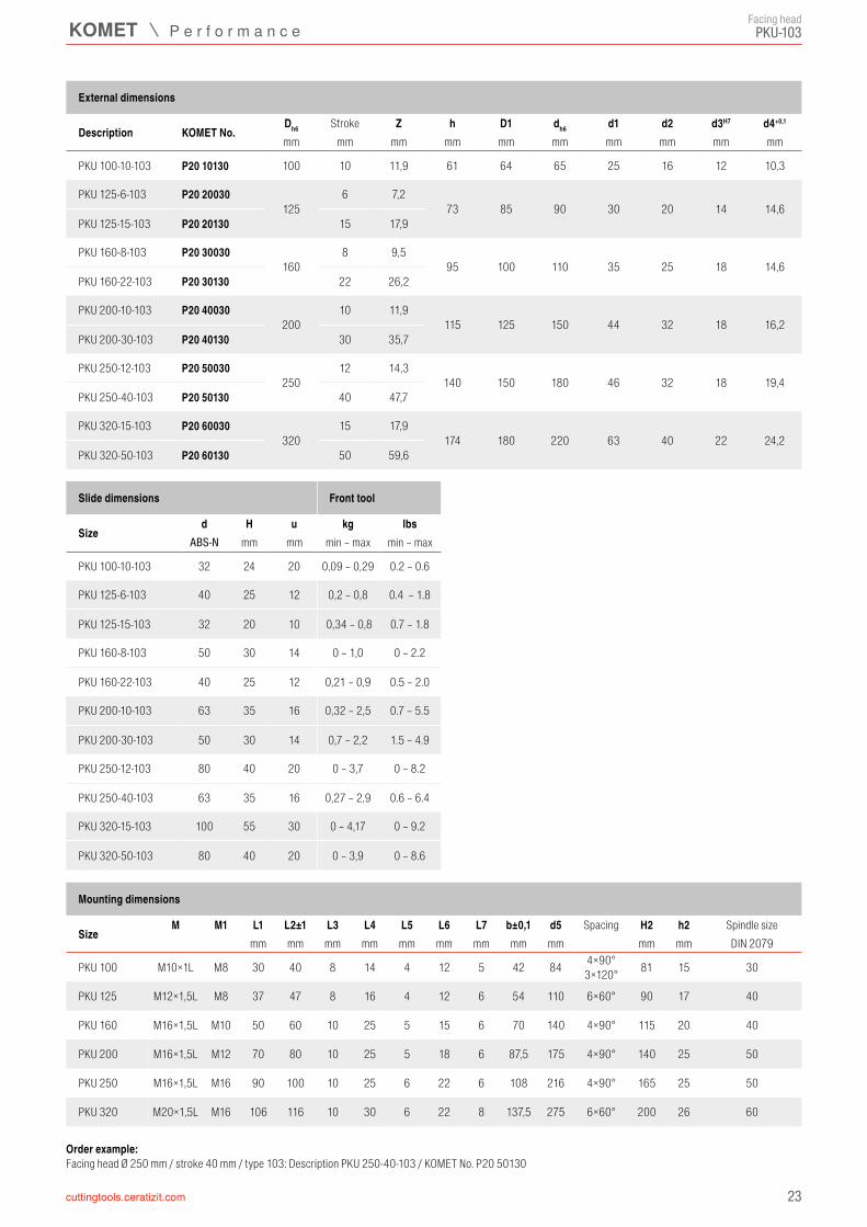
d H u kg lbsABS-N
PKU 100-10-103 32 24 20 0,09 – 0,29 0.2 – 0.6
PKU 125-6-103 40 25 12 0,2 – 0,8 0.4 – 1.8
PKU 125-15-103 32 20 10 0,34 – 0,8 0.7 – 1.8
PKU 160-8-103 50 30 14 0 – 1,0 0 – 2.2
PKU 160-22-103 40 25 12 0,21 – 0,9 0.5 – 2.0
PKU 200-10-103 63 35 16 0,32 – 2,5 0.7 – 5.5
PKU 200-30-103 50 30 14 0,7 – 2,2 1.5 – 4.9
PKU 250-12-103 80 40 20 0 – 3,7 0 – 8.2
PKU 250-40-103 63 35 16 0,27 – 2,9 0.6 – 6.4
PKU 320-15-103 100 55 30 0 – 4,17 0 – 9.2
PKU 320-50-103 80 40 20 0 – 3,9 0 – 8.6
23
PKU-103
External dimensions
Description KOMET No.Stroke
mm mm mm mm mm mm mm mm mm mm
Mounting dimensions
SizeSpacing Spindle size
mm mm mm mm mm mm mm mm mm mm mm DIN 2079
Slide dimensions Front tool
Sizemm mm min – max min – max
Facing head
Order example: Facing head Ø 250 mm / stroke 40 mm / type 103: Description PKU 250-40-103 / KOMET No. P20 50130
PKU-...
KOMdrive PKU-...
1 PKU 100 0,4 kg 0.9 lbs
2 PKU 125 0,6 kg 1.3 lbs
3 PKU 160 0,9 kg 2.0 lbs
4 PKU 200 2,0 kg 4.4 lbs
5 PKU 250 2,8 kg 6.17 lbs
24
PKU 100 PKU 125 PKU 160 PKU 200 PKU 250
500 1000 1500 2000 2500 3000 3500 4000 4500 5000 5500 6000
5
4
3
2
1
90 ml5.5 in³80 ml
4.9 in³70 ml
4.3 in³60 ml
3.7 in³50 ml
3.1 in³40 ml
2.4 in³30 ml
1.8 in³20 ml
1.2 in³10 ml
0.6 in³
40 000 N8800 pound force
30 000 N6600 pound force
25 000 N5500 pound force
20 000 N4400 pound force
15 000 N3300 pound force
10 000 N2200 pound force
5 000 N1100 pound force
* Spindle speed [rpm]Drawbar forces shown are valid for maximum weight of front tool.
Lubr
icatio
n volu
me
max. weight of front tool
Technical notes
Technical notes
stroke = start and end positionThe diagram serves as a guideline. A specific calculation can be produced with consideration to all parameters.
Drawbar force
Draw
bar f
orce
*Spindle speed [rpm]
Slide movement: 150 m / 6,000 in. (corresponds to one shift, 8 h)Lubrication requirements
Lubrication volume required for one shiftThe values specified are guide values and must, where required, be adjusted to the application conditions such as rotation speed, stroke and environmental influences such as coolant, dirt, etc.
LubricantsWe recommend Mobilux EP004 liquid grease for all speed ranges. Furthermore, it is also possible to use slideway oils according to DIN 51502 with the identifier CG-L68 or CG-L220 (CG-L220 is preferred for speeds from 700 rpm).The relevant commercial names of the mineral oil companies for slide-way oils can be ascertained from the machine lubrication instructions.These lubrication instructions apply to all generating tools supplied by KOMET.
d2
h3
d3d1
h2
d4
α
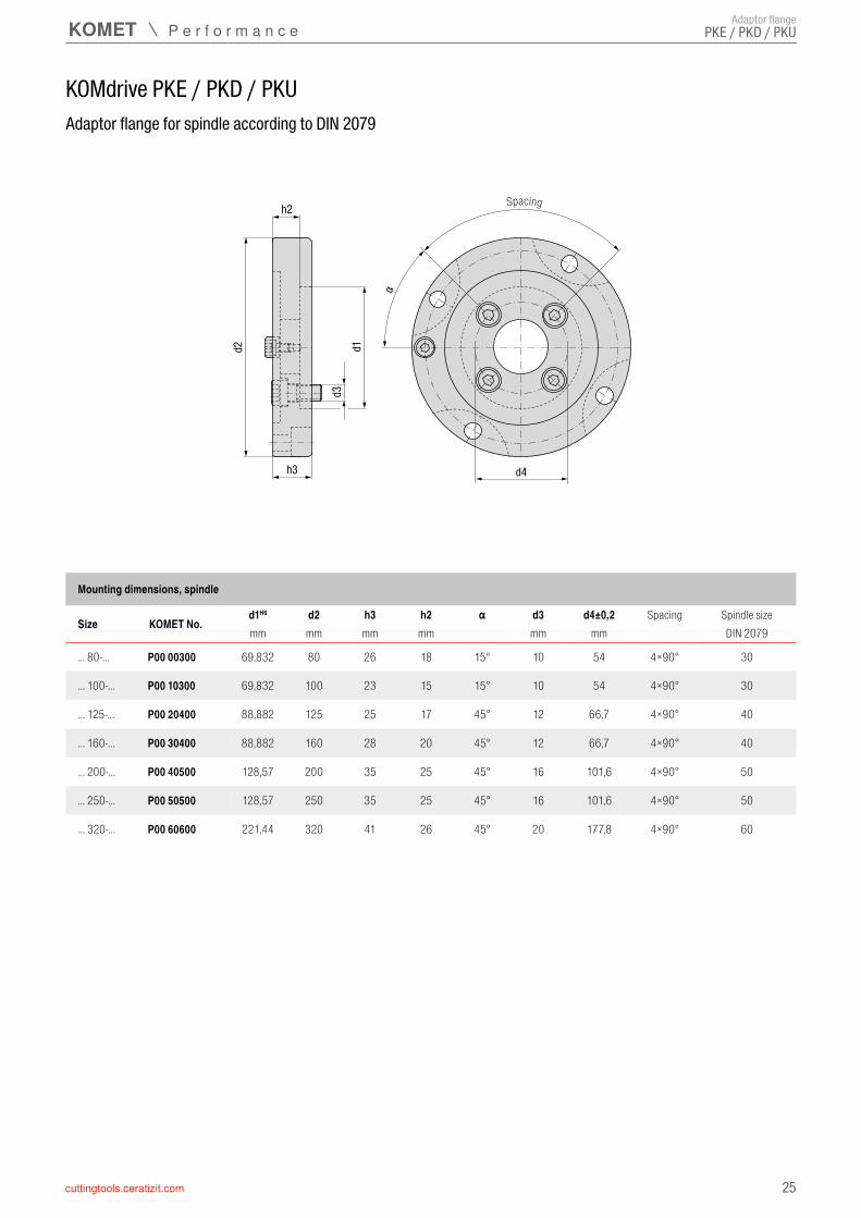
KOMdrive PKE / PKD / PKU
PKE / PKD / PKU
d1H6 d2 h3 h2 α d3 d4±0,2
... 80-... P00 00300 69,832 80 26 18 15° 10 54 4×90° 30
... 100-... P00 10300 69,832 100 23 15 15° 10 54 4×90° 30
... 125-... P00 20400 88,882 125 25 17 45° 12 66,7 4×90° 40
... 160-... P00 30400 88,882 160 28 20 45° 12 66,7 4×90° 40
... 200-... P00 40500 128,57 200 35 25 45° 16 101,6 4×90° 50
... 250-... P00 50500 128,57 250 35 25 45° 16 101,6 4×90° 50
... 320-... P00 60600 221,44 320 41 26 45° 20 177,8 4×90° 60
25
Adaptor flange
Adaptor flange for spindle according to DIN 2079
Mounting dimensions, spindle
Size KOMET No.Spacing Spindle size
mm mm mm mm mm mm DIN 2079
Spacing
Adaptor flange

PKE / PKD / PKU
26
Assembly variants
Assembly using stud bolt per DIN 939
Assembly using threaded insert/stud bolt with PKE 160-..-101-QA-IK-F
When assembling the stud bolt provided, it is necessary to install threaded inserts in two holes.The threads are adapted to the correct size through usage of the threaded inserts provided.
Threaded insert assembly: Observe direction (position of the slot). Screw in the threaded insert until slightly recessed or flush in accordance with the assembly instructions, and secure with medium-tight screw lock.Use the specified tools or other suitable auxiliary aids to screw in the threaded inserts.
Stud bolt assembly:When assembling the stud bolt, make sure that it is screwed into the threaded insert with the short thread length.A failure to observe this instruction will result in housing damage!
When assembling the stud bolt, make sure that it is screwed into the housing with the short thread length.
A failure to observe this instruction will result in housing damage!
Stud bolt DIN939
Washer DIN125-B
Hex nut ISO 4035
Intermediate flange
Stud bolt DIN939
Intermediate flange
Threaded insert
M8 → max. 12 NmM10 → max. 20 Nm
Washer DIN125-B
Hex nut ISO 4035M8 → max. 12 NmM10 → max. 20 Nm
Assembly variants

PKE / PKD / PKU
27
Assembly variants
Assembly using cylinder head screws per ISO 4762
Auxiliary aids for assembly/removal of the threaded insert
Assembly variants
When assembling with cylinder head screws, the optional threaded inserts must not be fitted; remove if necessary.
M10x60 → max. 35 NmM10x80 → max. 35 Nm
Screwing in by hand usually takes place with the hand tool via the internal thread of the threaded insert:
Screw on the threaded sleeve, note the slot position! Make sure that the screw does not point into the cutting edge geometry after locking with the nut.
Screw in the threaded insert up to approx. 0.1-0.2 mm below the tool surface (in case of makeshift assembly using screw and nut, screw in the threaded insert until flush as a minimum). Ensure vertical assembly.
Counter-lock the nut, otherwise the threaded insert will be unscrewed again. Then unscrew the hand tool or screw/nut.
Makeshift screwing in with screw/nut:
Screw in using hand tool:
28
Workpiece: gear caseMachining:
▲ finishbore bearing Ø 80H7 / Ø 100H7 (Ø 3.149”+0.00125” and Ø 3.937”+0.0014”) with bridge mounted tools
▲ retract after boring ▲ face turn with slide
Cutting data: Ø 80 / 100 mm Ø 3.149“ / 3.937“vc = 400 m/min 1,300 sfmn = 1591 min–1 1,591 rpmf = 0,11 mm/rev 0.0044 iprvf = 175 mm/min 6.89 ipm
Machining examplesFacing head
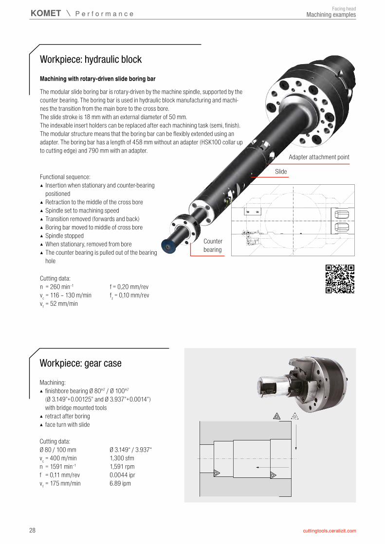
Machining with rotary-driven slide boring bar
Workpiece: hydraulic block
The modular slide boring bar is rotary-driven by the machine spindle, supported by the counter bearing. The boring bar is used in hydraulic block manufacturing and machi-nes the transition from the main bore to the cross bore.The slide stroke is 18 mm with an external diameter of 50 mm.The indexable insert holders can be replaced after each machining task (semi, finish).The modular structure means that the boring bar can be flexibly extended using an adapter. The boring bar has a length of 458 mm without an adapter (HSK100 collar up to cutting edge) and 790 mm with an adapter.
Functional sequence: ▲ Insertion when stationary and counter-bearing positioned
▲ Retraction to the middle of the cross bore ▲ Spindle set to machining speed ▲ Transition removed (forwards and back) ▲ Boring bar moved to middle of cross bore ▲ Spindle stopped ▲ When stationary, removed from bore ▲ The counter bearing is pulled out of the bearing hole
Cutting data:n = 260 min–1 f = 0,20 mm/revvc = 116 – 130 m/min fz = 0,10 mm/revvf = 52 mm/min
Adapter attachment point
Slide
Counter bearing
29
Workpiece: gear case
Machining examplesFacing head
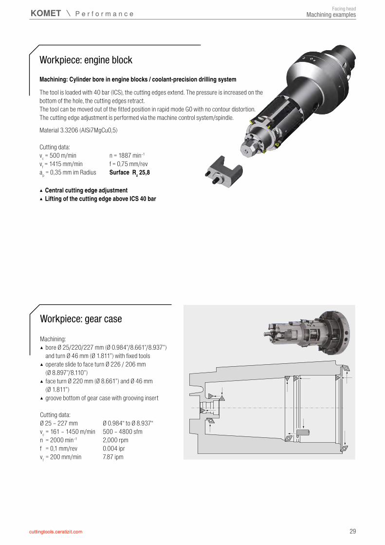
Machining: ▲ bore Ø 25/220/227 mm (Ø 0.984”/8.661”/8.937”) and turn Ø 46 mm (Ø 1.811”) with fixed tools
▲ operate slide to face turn Ø 226 / 206 mm (Ø 8.897”/8.110”)
▲ face turn Ø 220 mm (Ø 8.661”) and Ø 46 mm (Ø 1.811”)
▲ groove bottom of gear case with grooving insert
Cutting data: Ø 25 – 227 mm Ø 0.984“ to Ø 8.937“vc = 161 – 1450 m/min 500 – 4800 sfmn = 2000 min–1 2,000 rpmf = 0,1 mm/rev 0.004 iprvf = 200 mm/min 7.87 ipm
Machining: Cylinder bore in engine blocks / coolant-precision drilling system
Workpiece: engine block
The tool is loaded with 40 bar (ICS), the cutting edges extend. The pressure is increased on the bottom of the hole, the cutting edges retract.The tool can be moved out of the fitted position in rapid mode G0 with no contour distortion.The cutting edge adjustment is performed via the machine control system/spindle.
▲ Central cutting edge adjustment ▲ Lifting of the cutting edge above ICS 40 bar
Material 3.3206 (AlSi7MgCu0,5)
Cutting data: vc = 500 m/min n = 1887 min–1
vf = 1415 mm/min f = 0,75 mm/revap = 0,35 mm im Radius Surface Rz 25,8

30
Workpiece: bearing housingMachining:
▲ bore Ø 40 mm (Ø 1.575”) and chamfer 1×45°; Turn outer Ø 95 mm (Ø 3.740”) and step Ø 86 mm (Ø 3.386”)
▲ lift of cutting edges ▲ turn both faces
Cutting data: Ø 50 mm / 1.575“ Ø2 110 mm / 2 4.331“vc = 180 m/min 600 sfmn1 = 1150 min–1 1,550 rpmn2 = 520 min–1 520 rpmf = 0,15 mm/rev 0.006 iprvf1 = 172 mm/min 6.77 ipmvf2 = 80 mm/min 3.15 ipm
Workpiece: Tube end machining
Machining: ▲ chamfer bore ▲ bore inner contour including undercut ▲ chamfer outer diameter and plungecut the face ▲ cut thread in multiple passes ▲ centrally located front tool is exchangeable for machi-ning different tube diameters
Cutting data: Ø 94 mm Ø 3.700“vc = 220 m/min 725 sfmn = 1350 min–1 1,350 rpmf = 0,12 mm/rev 1,35053 iprvf = 162 mm/min 6.75 ipm
Machining examplesFacing head
31
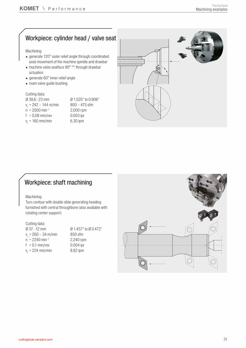
Workpiece: shaft machining
Workpiece: cylinder head / valve seat
Machining: ▲ generate 120° outer relief angle through coordinated axial movement of the machine spindle and drawbar
▲ machine valve sealface 90°–30’ through drawbar actuation
▲ generate 60° inner relief angle ▲ ream valve guide bushing
Cutting data: Ø 38,6 - 23 mm Ø 1.520“ to 0.906“vc = 242 – 144 m/min 800 – 475 sfmn = 2000 min–1 2,000 rpmf = 0,08 mm/rev 0.003 iprvf = 160 mm/min 6.30 ipm
Machining: Turn contour with double slide generating heading furnished with central throughbore (also available with rotating center support)
Cutting data: Ø 37 - 12 mm Ø 1.457“ to Ø 0.472“vc = 260 – 34 m/min 850 sfmn = 2240 min–1 2,240 rpmf = 0,1 mm/rev 0.004 iprvf = 224 mm/min 8.82 ipm
Machining examplesFacing head

32
40°
45°
26°
M d3
Modification 1Rack angle for various transmission ratios. All facing heads are also availa-ble with transmission ratios of 1:1 and 1:2.
Modification 2Drawbar connection with different locating diameter and thread. Capable to connect with existing machines.
Modification 3Additional mounting holes to install bridge. Installation of fixed tools to combine boring and facing operations.
Modification 4Modified mounting hole pattern in slides allows the installation of existing cutting tools.
Modification 5Coolant supply through the face of the spindle. Improved chip control and chip removal in drilling and boring operations.
Below is a listing of modifications to standard facing heads which are available upon request. Replacement parts such as drawbars, gear racks and slides are stocked as semifinished components.
Modified facing heads
Modified standard facing headsFacing head

33
KOMtronic SMS / UAC / UAD
AussteuerwerkzeugFor special purpose machines
Facing heads with integrated measuring system and KOMtronic U-axis systems for spindle integration
Produce turning contours economically when working with a stationary workpiece
Based on decades of experience producing facing heads for special purpose machines, KOMET is expanding its product range to include KOMtronic systems for spindle integration for different installation and usage requirements for facing heads.
▲ Facing heads with direct encoder on the slide ▲ KOMtronic systems for spindle integration with own drive

KOMlife
34
Free KOMlife app in the App Store for iOS devices
KOMlife deactivated
Tool rotates
KOMlife activated
Maintenance interval reached
Digital display of production data
QR code screen
Try me out with the KOMlife app!
▲ Number of operating hours ▲ Current status of the maintenance interval ▲ Dimensions: 30 x 30 x 11 mm
▲ With linear or rotary acceleration greater than 1.5 g ▲ Required installation space: 30.1 x 30.1 x 10 mm
▲ Adjustable maintenance interval depending on the application
▲ Visualisation of the necessary tool maintenance with a red, flashing LED
▲ Digital acquisition and export of production data via smartphone and KOMlife app
▲ Display of serial number and production data
Ergonomic display unit
Can be used with various tool systems
Customer-specifi c adaptation
Patented, dynamic QR codeSpecial tools
Actuating tools
Advantages ▲ Planned, preventative maintenanceRegular, advance maintenance planning can increase tool service life and ensure workpiece quality at all times.
▲ Digital production data acquisitionThrough a patented, dynamic QR code and the KOMlife app.
▲ Assessment of tool useConclusions can be drawn about the status and load of the cutting edge by gathering data on tool use.
▲ Not dependent on tool manufacturerKOMlife can be easily integrated into new and existing linear and rotating systems, irrespective of the tool manufacturer.
Application
Autonomous acquisition and processing of production data directly on the respective tool
Technical dataLithium battery CR2032Battery life Approx. 2 yearsMin. acceleration 1,5 gMin. tool diameter 50 mm
Benefi ts
KOMlifeAutonomous acquisition of production data accurate to the second

35
Free KOMlife app in the App Store for iOS devices
KOMlife deactivated
Tool rotates
KOMlife activated
Maintenance interval reached
Digital display of production data
QR code screen
Try me out with the KOMlife app!
▲ Number of operating hours ▲ Current status of the maintenance interval ▲ Dimensions: 30 x 30 x 11 mm
▲ With linear or rotary acceleration greater than 1.5 g ▲ Required installation space: 30.1 x 30.1 x 10 mm
▲ Adjustable maintenance interval depending on the application
▲ Visualisation of the necessary tool maintenance with a red, flashing LED
▲ Digital acquisition and export of production data via smartphone and KOMlife app
▲ Display of serial number and production data
Ergonomic display unit
Can be used with various tool systems
Customer-specifi c adaptation
Patented, dynamic QR codeSpecial tools
Actuating tools
Advantages ▲ Planned, preventative maintenanceRegular, advance maintenance planning can increase tool service life and ensure workpiece quality at all times.
▲ Digital production data acquisitionThrough a patented, dynamic QR code and the KOMlife app.
▲ Assessment of tool useConclusions can be drawn about the status and load of the cutting edge by gathering data on tool use.
▲ Not dependent on tool manufacturerKOMlife can be easily integrated into new and existing linear and rotating systems, irrespective of the tool manufacturer.
Application
Autonomous acquisition and processing of production data directly on the respective tool
Technical dataLithium battery CR2032Battery life Approx. 2 yearsMin. acceleration 1,5 gMin. tool diameter 50 mm
Benefi ts
KOMlifeAutonomous acquisition of production data accurate to the second

UNITED. EXPERIENCED. METAL CUTTING.
The product brand CERATIZIT stands for high-quality indexable insert tools. The products are characterized by their high quality and contain the DNA of many years of experience in the development and production of carbide tools.
SPECIALIST FOR INDEXABLE INSERT TOOLS FOR TURNING, MILLING AND GROOVING
WNT is synonymous with product diversity: solid carbide and HSS rotating tools, tool holders and efficient workholding solutions are all part of this brand.
EXPERTS FOR ROTATING TOOLS, TOOL HOLDERS AND CLAMPING SOLUTIONS
Solid carbide drills specially developed for the aerospace industry bear the product name KLENK. The highly specialised products are specifically designed for machining lightweight materials.
CUTTING TOOLS FOR THE AEROSPACE INDUSTRY
High-precision drilling, reaming, countersinking and boring is a matter of expertise: efficient tooling solutions for drilling and mechatronic tools are therefore part of the KOMET brand name.
THE QUALITY LABEL FOR EFFICIENT BORE PRODUCTION
12/20
20 –
94 22
1 010
12