ce power wheel supplemental manual - crafco
TRANSCRIPT
CE POWER WHEEL SUPPLEMENTAL MANUAL
REV 0 – 1/1/2019
Page 2 of 13
Revision Date
Page 3 of 13
Page 4 of 13
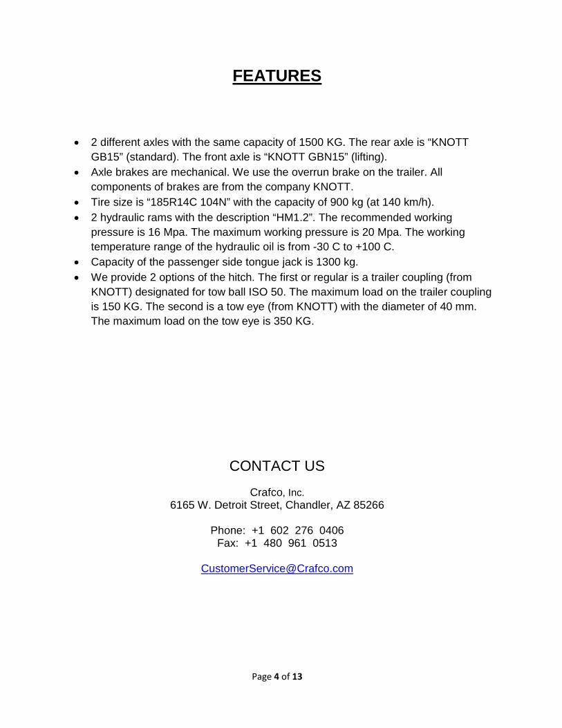
FEATURES
• 2 different axles with the same capacity of 1500 KG. The rear axle is “KNOTT GB15” (standard). The front axle is “KNOTT GBN15” (lifting).
• Axle brakes are mechanical. We use the overrun brake on the trailer. All components of brakes are from the company KNOTT.
• Tire size is “185R14C 104N” with the capacity of 900 kg (at 140 km/h). • 2 hydraulic rams with the description “HM1.2”. The recommended working
pressure is 16 Mpa. The maximum working pressure is 20 Mpa. The working temperature range of the hydraulic oil is from -30 C to +100 C.
• Capacity of the passenger side tongue jack is 1300 kg. • We provide 2 options of the hitch. The first or regular is a trailer coupling (from
KNOTT) designated for tow ball ISO 50. The maximum load on the trailer coupling is 150 KG. The second is a tow eye (from KNOTT) with the diameter of 40 mm. The maximum load on the tow eye is 350 KG.
CONTACT US
Crafco, Inc. 6165 W. Detroit Street, Chandler, AZ 85266
Phone: +1 602 276 0406
Fax: +1 480 961 0513
Page 5 of 13
OPERATING INSTRUCTIONS
• The power wheel has been designed to be used on paved roads, parking lots, highways and run-/taxiways. We do not recommend to use the power wheel when the slope is greater than 7%. Do not use the power wheel when driving up or down the loading ramp.
• Check closely all hydraulic hoses, wheel nuts and screws before start to use the power wheel (on a daily basis).
• Damaged hydraulic hoses need to be removed and replaced before start to use the power wheel.
• Unfastened nuts or screws need to be tightened before start to use the power wheel. • Do not adjust the hydraulic pressure. The optimal hydraulic pressure has been pre-set by
the manufacturer. • Only trained persons can operate the power wheel.
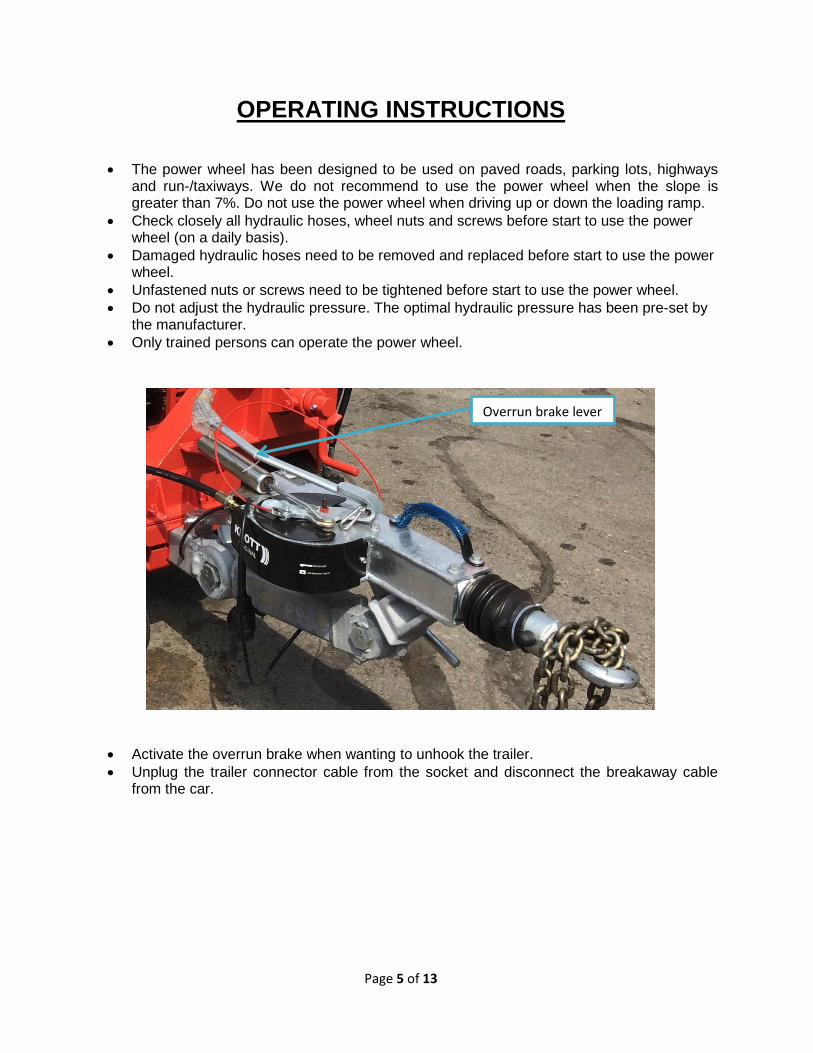
• Activate the overrun brake when wanting to unhook the trailer. • Unplug the trailer connector cable from the socket and disconnect the breakaway cable
from the car.
Overrun brake lever
Page 6 of 13
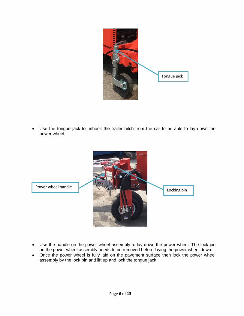
• Use the tongue jack to unhook the trailer hitch from the car to be able to lay down the power wheel.
• Use the handle on the power wheel assembly to lay down the power wheel. The lock pin on the power wheel assembly needs to be removed before laying the power wheel down.
• Once the power wheel is fully laid on the pavement surface then lock the power wheel assembly by the lock pin and lift up and lock the tongue jack.
Tongue jack
Locking pin Power wheel handle
Page 7 of 13
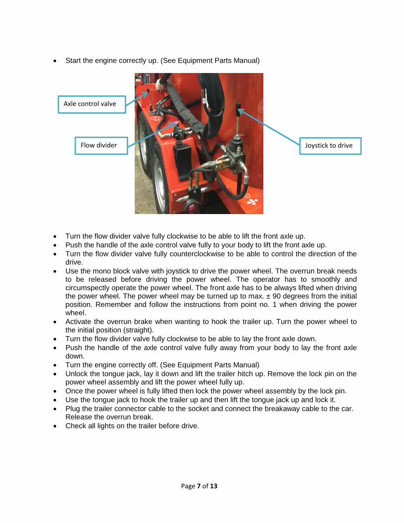
• Start the engine correctly up. (See Equipment Parts Manual)
• Turn the flow divider valve fully clockwise to be able to lift the front axle up. • Push the handle of the axle control valve fully to your body to lift the front axle up. • Turn the flow divider valve fully counterclockwise to be able to control the direction of the
drive. • Use the mono block valve with joystick to drive the power wheel. The overrun break needs
to be released before driving the power wheel. The operator has to smoothly and circumspectly operate the power wheel. The front axle has to be always lifted when driving the power wheel. The power wheel may be turned up to max. ± 90 degrees from the initial position. Remember and follow the instructions from point no. 1 when driving the power wheel.
• Activate the overrun brake when wanting to hook the trailer up. Turn the power wheel to the initial position (straight).
• Turn the flow divider valve fully clockwise to be able to lay the front axle down. • Push the handle of the axle control valve fully away from your body to lay the front axle
down. • Turn the engine correctly off. (See Equipment Parts Manual) • Unlock the tongue jack, lay it down and lift the trailer hitch up. Remove the lock pin on the
power wheel assembly and lift the power wheel fully up. • Once the power wheel is fully lifted then lock the power wheel assembly by the lock pin. • Use the tongue jack to hook the trailer up and then lift the tongue jack up and lock it. • Plug the trailer connector cable to the socket and connect the breakaway cable to the car.
Release the overrun break. • Check all lights on the trailer before drive.
Joystick to drive
Axle control valve
Flow divider
Page 8 of 13
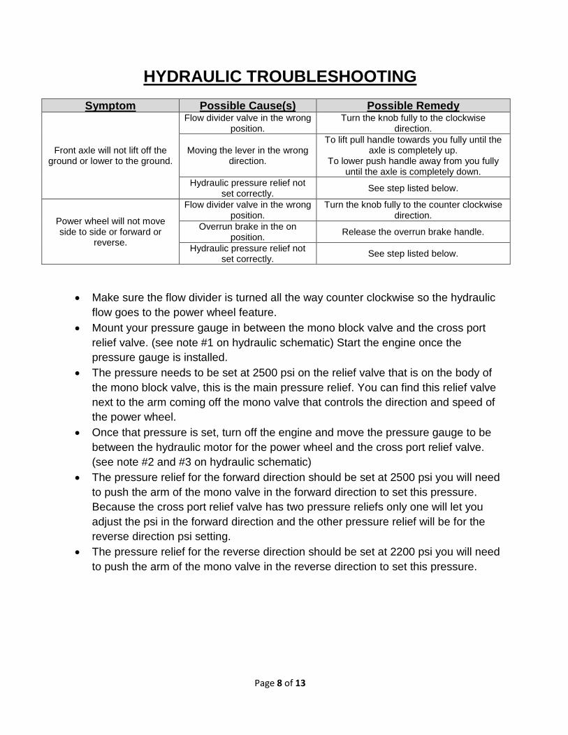
HYDRAULIC TROUBLESHOOTING
Symptom Possible Cause(s) Possible Remedy
Front axle will not lift off the ground or lower to the ground.
Flow divider valve in the wrong position.
Turn the knob fully to the clockwise direction.
Moving the lever in the wrong direction.
To lift pull handle towards you fully until the axle is completely up.
To lower push handle away from you fully until the axle is completely down.
Hydraulic pressure relief not set correctly. See step listed below.
Power wheel will not move side to side or forward or
reverse.
Flow divider valve in the wrong position.
Turn the knob fully to the counter clockwise direction.
Overrun brake in the on position. Release the overrun brake handle.
Hydraulic pressure relief not set correctly. See step listed below.
• Make sure the flow divider is turned all the way counter clockwise so the hydraulic flow goes to the power wheel feature.
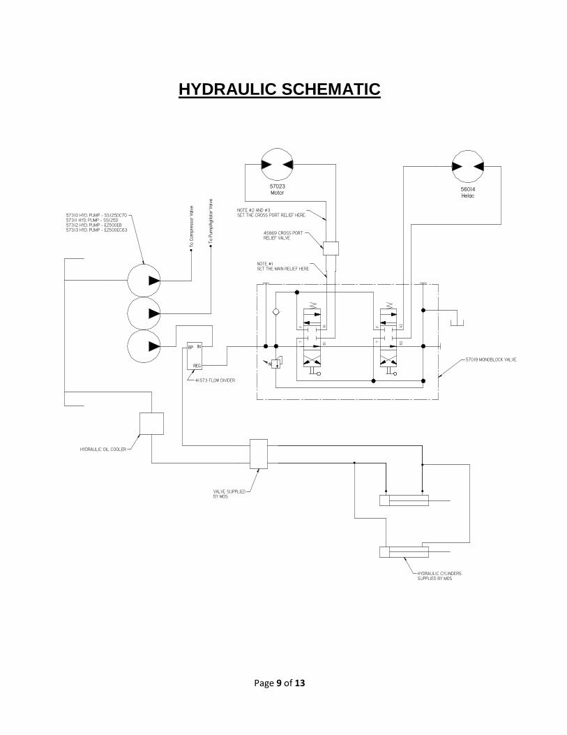
• Mount your pressure gauge in between the mono block valve and the cross port relief valve. (see note #1 on hydraulic schematic) Start the engine once the pressure gauge is installed.
• The pressure needs to be set at 2500 psi on the relief valve that is on the body of the mono block valve, this is the main pressure relief. You can find this relief valve next to the arm coming off the mono valve that controls the direction and speed of the power wheel.
• Once that pressure is set, turn off the engine and move the pressure gauge to be between the hydraulic motor for the power wheel and the cross port relief valve. (see note #2 and #3 on hydraulic schematic)
• The pressure relief for the forward direction should be set at 2500 psi you will need to push the arm of the mono valve in the forward direction to set this pressure. Because the cross port relief valve has two pressure reliefs only one will let you adjust the psi in the forward direction and the other pressure relief will be for the reverse direction psi setting.
• The pressure relief for the reverse direction should be set at 2200 psi you will need to push the arm of the mono valve in the reverse direction to set this pressure.
Page 9 of 13
HYDRAULIC SCHEMATIC
B2A2
TP
B1A1
TP
57023Motor
56014Helac
To C
ompr
esso
r Val
ve
To P
ump/
Agita
tor V
alve
57019 MONOBLOCK VALVE
45869 CROSS PORT RELIEF VALVE
41573 FLOW DIVIDER
VALVE SUPPLIEDBY MOS
HYDRAULIC CYLINDERSSUPPLIED BY MOS
57310 HYD. PUMP - SS125DC7057311 HYD. PUMP - SS125D57312 HYD. PUMP - EZ500EB57313 HYD. PUMP - EZ500EC63
HYDRAULIC OIL COOLER
IN
REG
BP
NOTE #1 SET THE MAIN RELIEF HERE
NOTE #2 AND #3SET THE CROSS PORT RELIEF HERE
Page 10 of 13
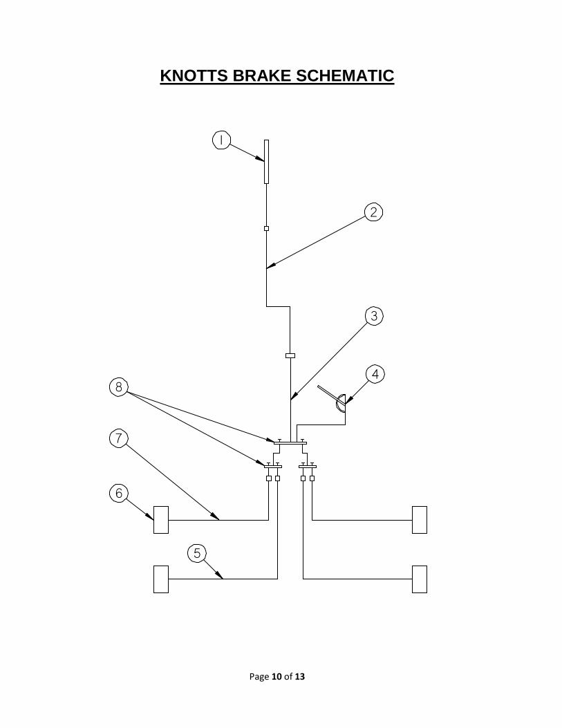
KNOTTS BRAKE SCHEMATIC
1
2
3
5
6
7
48
Page 11 of 13
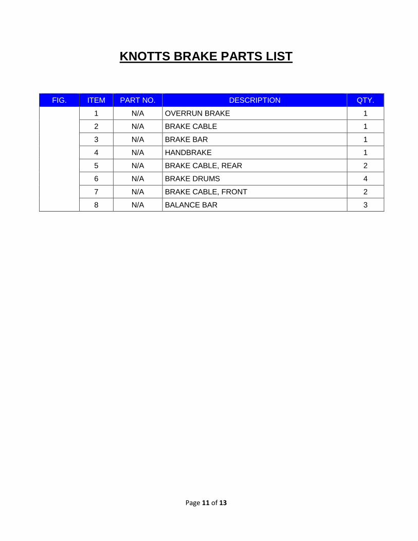
KNOTTS BRAKE PARTS LIST
FIG. ITEM PART NO. DESCRIPTION QTY.
1 N/A OVERRUN BRAKE 1
2 N/A BRAKE CABLE 1
3 N/A BRAKE BAR 1
4 N/A HANDBRAKE 1
5 N/A BRAKE CABLE, REAR 2
6 N/A BRAKE DRUMS 4
7 N/A BRAKE CABLE, FRONT 2
8 N/A BALANCE BAR 3

Page 12 of 13
---THIS PAGE INTENTIONALLY LEFT BLANK---

Page 13 of 13
©2019 Crafco, Inc.