ccna exploration1 chapter 7: osi data link layer · pdf fileccna exploration1 chapter 7: osi...
TRANSCRIPT

1© 2004, Cisco Systems, Inc. All rights reserved.
CCNA Exploration1 Chapter 7:OSI Data Link Layer
LOCAL CISCO ACADEMY ELSYS TUINSTRUCTOR: STELA STEFANOVA

222© 2004, Cisco Systems, Inc. All rights reserved.
Objectives
• Explain the role of Data Link layer protocols in data transmission;
• Describe how the Data Link layer prepares data for transmission on network media;
• Describe the different types of media accesscontrol methods;
• Identify several common logical network topologies and describe how the logical topology determines the media access control method for that network;
• Explain the purpose of encapsulating packets into frames to facilitate media access;
• Describe the Layer 2 frame structure and identify generic fields;
• Explain the role of header key frame and

333© 2004, Cisco Systems, Inc. All rights reserved.
Data Link Layer – Accessing the MediaService the Data Link Layer provides as it prepares communication for transmission on specific media

444© 2004, Cisco Systems, Inc. All rights reserved.
Data Link Layer – Accessing the Media
Data Link layer basic services:
• Allows the upper layers to access the media using techniques – framing;
• Controls how data is placed onto the media and is received from the mediausing techniques:
- media access control;- error detection.

555© 2004, Cisco Systems, Inc. All rights reserved.
Data Link Layer – Accessing the Media
Frame - Data Link layer PDU;Node - Layer 2 notation for
network devices connected to a common medium;
Media/medium- physical means for the transfer of information between two nodes;- material that actually carriesthe signals representing the transmitted data;- is the physical coppercable, optical fiber, or atmosphere through which the signals travel.
Network (Physical)• - two or more nodes
connected to a common medium;
• physical networks represent the interconnection of devices on a common media.
Data Link layer basic terms
666© 2004, Cisco Systems, Inc. All rights reserved.
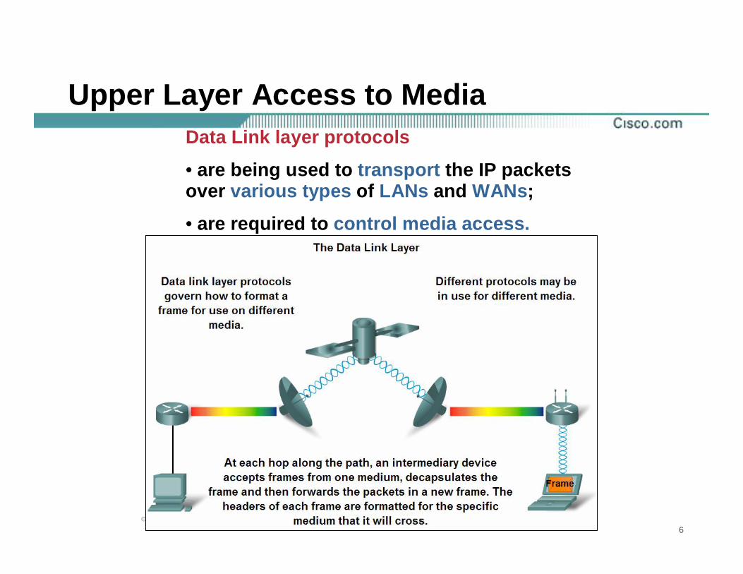
Upper Layer Access to MediaData Link layer protocols
• are being used to transport the IP packets over various types of LANs and WANs;
• are required to control media access.

777© 2004, Cisco Systems, Inc. All rights reserved.
Controlling Transfer across Local MediaFraming - preparing a packet for transmission on a given media

888© 2004, Cisco Systems, Inc. All rights reserved.
Controlling Transfer across Local Media
Media access control methods• techniques used for getting the frame on and off media;
• for the data to be transferred across a number of different media, different media access control methods may be required during the course of a single communication;
• define the processes by which network devices can access the network media and transmit framesin diverse network environments.

999© 2004, Cisco Systems, Inc. All rights reserved.
Data Link Layer – Creating a Frame
Data Link layer frame:• Data - packet from
the Network layer;• Header - Contains
control information, such addressing, and is located at the beginning of the PDU;
• Trailer - Contains control informationadded to the end of the PDU.
The Data Link layer prepares a packet for transport across the local media by encapsulating it with a header and a trailer to create a frame

101010© 2004, Cisco Systems, Inc. All rights reserved.
Data Link Layer – Creating a Frame
Data Link layerframe fields:
• Start and stop indicator fields -beginning and end limits of the frame;
• Naming or addressing fields;
• Type field - type of PDU contained in the frame;
• Quality - control fields;
• Data field - frame payload (Network layer packet).
Framing breaks the stream into decipherable groupings, with control information inserted in the header and trailer as values in different fields

111111© 2004, Cisco Systems, Inc. All rights reserved.
Data Link Layer – Connecting Upper Layer Services to the Media
The Data Link layer exists as a connecting layer between the software processes of the layers above it and the Physical layer below it.

121212© 2004, Cisco Systems, Inc. All rights reserved.
Data Link Layer – Connecting Upper Layer Services to the Media
Data Link layer• prepares the Network layer packets for transmission
across some form of media, be it copper, fiber, or the atmosphere;
• is embodied as a physical entity.
Ethernet Network Interface Card (NIC):• inserts into the system bus of a computer;• makes the connection between running software
processes on the computer and physical media;• is not solely a physical entity;• software associated with the NIC enables the NIC to
perform its intermediary functions of preparing datafor transmission and encoding the data as signals to be sent on the associated media.
131313© 2004, Cisco Systems, Inc. All rights reserved.
Data Link Sublayers
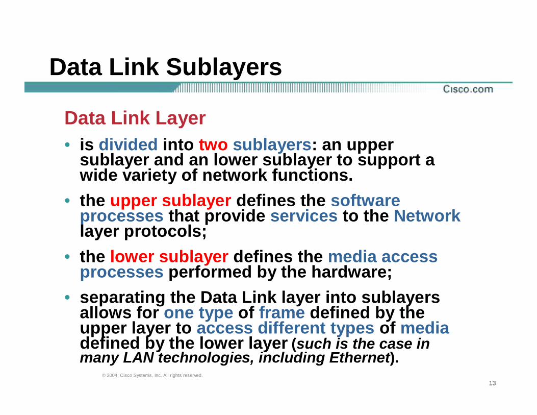
Data Link Layer• is divided into two sublayers: an upper
sublayer and an lower sublayer to support a wide variety of network functions.
• the upper sublayer defines the softwareprocesses that provide services to the Network layer protocols;
• the lower sublayer defines the media accessprocesses performed by the hardware;
• separating the Data Link layer into sublayersallows for one type of frame defined by theupper layer to access different types of mediadefined by the lower layer (such is the case in many LAN technologies, including Ethernet).

141414© 2004, Cisco Systems, Inc. All rights reserved.
Data Link SublayersData Link Sublayers:Logical Link Control (LLC)• places information in the frame that
identifies which Network layer protocol is being used for the frame;
• allows multiple Layer 3 protocols (IP and IPX), to utilize the same networkinterface and media.
Media Access Control (MAC)• provides Data Link layer addressing;• provides delimiting of data according
to the physical signaling requirements of the medium and the type of Data Link layer protocol in use.

151515© 2004, Cisco Systems, Inc. All rights reserved.
Data Link Layer – Connecting Upper Layer Services to the Media
Data Link layer Sublayers

161616© 2004, Cisco Systems, Inc. All rights reserved.
Data Link Layer – Standards and Protocols
Data Link layer services and specifications:• are defined by multiple standards based on a variety of technologies and media to which the protocols are applied;• some of the standards integrate both Layer 2 and Layer 1 services.
Engineering organizations:• describe the functional protocols and servicesat the Data Link layer;• set public and open standards and protocols;• communications companies may set and useproprietary protocols to take advantage of new advances in technology or market opportunities.

171717© 2004, Cisco Systems, Inc. All rights reserved.
Data Link Layer – Standards and ProtocolsEngineering organizations that define open standards and protocols that apply to the Data Link layer
Engineeringorganizations:• International Organization for Standardization (ISO)• Institute of Electrical and Electronics Engineers (IEEE)• American National Standards Institute (ANSI) • International Telecommunication Union (ITU)

181818© 2004, Cisco Systems, Inc. All rights reserved.
Media Access Control Techniques
Necessity for controlling access to the media
Media Access Control
• regulating the placement of data frames onto the media;
Method of media access control depends on:
• Media sharing - if and how the nodes share the media• Topology - how the connection between the nodes appears to the Data Link layer.

191919© 2004, Cisco Systems, Inc. All rights reserved.
Media Access Control Techniques
Media access control methods for shared media
Controlled Access• each node has its own time to usethe medium Contention-based Access• all nodes compete for the use of the medium

202020© 2004, Cisco Systems, Inc. All rights reserved.
Media Access Control Techniques
Controlled Access for Shared Media• network devices take turns, in sequence, to access the medium;• is also known as scheduled access or deterministic;• if a device does not need to access the medium, the opportunity to use the medium passes to the next device in line;• when one device places a frame on the media, no other device can do so until the frame has arrived at the destination and has been processed by the destination. • is well-ordered and provides predictable throughput;• can be inefficient because a device has to wait for itsturn before it can use the medium.

212121© 2004, Cisco Systems, Inc. All rights reserved.
Media Access Control Techniques
Controlled Access

222222© 2004, Cisco Systems, Inc. All rights reserved.
Media Access Control Techniques
Contention-based Access Methods for Shared Media• referred to as non-deterministic, contention-based methods;• allow any device to try to access the medium whenever it has data to send;• use a Carrier Sense Multiple Access (CSMA) process to first detect if the media is carrying a signal;• used by Ethernet and wireless networks;• do not have the overhead of controlled access methods (a mechanism for tracking whose turn it is to access the media is not required);• do not scale well under heavy media use;• if the number of nodes increases, the probability of successful media access without a collision decreases;• require a recovery mechanisms to correct errors due to these collisions further diminishes the throughput.

232323© 2004, Cisco Systems, Inc. All rights reserved.
Media Access Control TechniquesCarrier Sense Multiple Access (CSMA) process• if a carrier signal on the media from another node is detected, it means that another device is transmitting;• when the device attempting to transmit sees that the media is busy, it will wait and try again after a short time period;• if no carrier signal is detected, the device transmits its data;• is usually implemented in conjunction with a method for resolving the media contention.Data collision• it is possible that the CSMA process will fail and twodevices will transmit at the same time;• if occurs, the data sent by both devices will be corruptedand will need to be resent;Methods resolving the media contention:
- CSMA/Collision Detection;- CSMA/Collision Avoidance.

242424© 2004, Cisco Systems, Inc. All rights reserved.
Media Access Control Techniques
Contention based Access

252525© 2004, Cisco Systems, Inc. All rights reserved.
Media Access Control TechniquesCSMA/Collision Detection• the device monitors the media for the presence of a datasignal;• if a data signal is absent, indicating that the media is free, the device transmits the data;• if signals are then detected that show another device was transmitting at the same time, all devices stop sending and try again later;• is used by an Ethernet.CSMA/Collision Avoidance• device examines the media for the presence of a data signal;• if the media is free, the device sends a notification across the media of its intent to use it;• the device then sends the data;• is used by 802.11 wireless networking technologies.

262626© 2004, Cisco Systems, Inc. All rights reserved.
Media Access Control for Non-Shared MediaFull Duplex and Half Duplex as it relates toMedia Access Control for non-shared media

272727© 2004, Cisco Systems, Inc. All rights reserved.
Media Access Control for non-shared mediaMedia Access Control for non-shared media protocols
• require little or no control before placing frames onto the media;• have simpler rules and procedures for media access control.
In Point-to-point topologies:• the media interconnects just two nodes;• the nodes do not have to share the media with other hosts or determine if a frame is destined for that node;• Data Link layer protocols have little to do for controlling non-shared media access. • the Data Link layer has to consider whether the communication is half-duplex or full-duplex.

282828© 2004, Cisco Systems, Inc. All rights reserved.
Media Access Control for non-shared media
Half-duplex communication• means that the devices can both transmit and receive on the media but cannot do so simultaneously;• Ethernet has established arbitration rules for resolving conflicts arising from instances when more than onestation attempts to transmit at the same time.
Full-duplex communication• both devices can transmit and receive on the media at the same time;• the Data Link layer assumes that the media is available for transmission for both nodes at any time;• there is no media arbitration necessary in the Data Link layer.

292929© 2004, Cisco Systems, Inc. All rights reserved.
Media Access Control for Non-Shared Media
Full Duplex Communication

303030© 2004, Cisco Systems, Inc. All rights reserved.
Media Access Control for Non-Shared Media
Half Duplex Communication

313131© 2004, Cisco Systems, Inc. All rights reserved.
Physical and Logical Topology
Topology of a network• is the arrangement or relationship of
the network devices and the interconnections between them;
• can be viewed at the physical leveland the logical level.
Physical topology• is an arrangement of the nodes and
the physical connections between them;
• the representation of how the media is used to interconnect the devicesis the physical topology.

323232© 2004, Cisco Systems, Inc. All rights reserved.
Physical and Logical Topology
Logical topology• is the way a network transfers frames from one
node to the next;• the arrangement consists of virtual connections
between the nodes of a network independent of their physical layout;
• are defined by Data Link layer protocols;• influences the type of network framing and media
access control used;• is closely related to the mechanism used to manage
network access;• access methods provide the procedures to manage
network access so that all stations have access.
333333© 2004, Cisco Systems, Inc. All rights reserved.
Physical and Logical Topology
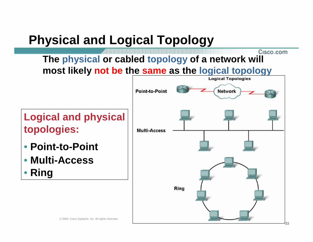
Logical and physical topologies:• Point-to-Point • Multi-Access • Ring
The physical or cabled topology of a network will most likely not be the same as the logical topology

343434© 2004, Cisco Systems, Inc. All rights reserved.
Physical and Logical TopologyLogical Point-to-Point Networks• the end nodes communicating in a point-to-point networkcan be physically connected via a number of intermediate devices;• the use of physical devices in the network does not affectthe logical topology;• the source and destination node may be indirectly connected to each other over some geographical distance.Virtual Circuit• is a logical connection created within a network between two network devices;• is important logical communication construct used by some Layer 2 technologies;• the two nodes on either end of the virtual circuit exchangethe frames with each other.

353535© 2004, Cisco Systems, Inc. All rights reserved.
Logical Point-to-Point Networks
The media access method used by the Data Link protocol is determined by the logical point-to-point topology, not the physical topology.

363636© 2004, Cisco Systems, Inc. All rights reserved.
Logical Point-to-Point NetworksPoint-to-point topology
In point-to-point networks:
Half-duplex link - if data can only flow in one direction at a time;
Full-duplex link - If data can successfully flow across the link from each node simultaneously.

373737© 2004, Cisco Systems, Inc. All rights reserved.
Logical Multi-access Topology
Logical Multi-access Topology• enables a number of nodes to communicate by using the same shared media;• data from only one node can be placed on the medium at any one time;• every node sees all the frames that are on the medium, but only the node to which the frame is addressed processes the contents of the frame;• requires a Data Link media access control method to regulate the transmission of data and thereby reduce collisions between different signals; • media access control methods - CSMA/CD or CSMA/CA. (Token Passing methods can also be used).

383838© 2004, Cisco Systems, Inc. All rights reserved.
Logical Multi-access Topology
Logical Multi-access Topology
1
2
3

393939© 2004, Cisco Systems, Inc. All rights reserved.
Logical Ring TopologyLogical Ring Topology• each node in turn receives a frame;• if the frame is not addressed to the node, the node
passes the frame to the next node;• uses a controlled media access control technique called
token passing;• nodes in a logical ring topology remove the frame from
the ring, examine the address, and send it on if it is notaddressed for that node;
• in a ring, all nodes around the ring- between the source and destination node examine the frame;
• only one frame at a time is usually carried by the media;• if there is no data being transmitted, a signal (known as
a token) may be placed on the media and a node can only place a data frame on the media when it has the token.

404040© 2004, Cisco Systems, Inc. All rights reserved.
Logical Ring Topology
Logical Ring Topology

414141© 2004, Cisco Systems, Inc. All rights reserved.
Media Access Control Addressing and Framing Data
Data Link Layer Protocols – the Frame

424242© 2004, Cisco Systems, Inc. All rights reserved.
Data Link Layer Protocols – FrameData Link layer frame basic parts:• Header• Data• TrailerData Link layer protocol:• encapsulates the Layer 3 PDU within the data field of the frame;• the structure of the frame and the fields contained in the header and trailer vary according to the protocol; • describes the features required for the transport of packets across different media;• takes the frame off the media, the framing information is read and discarded;• there is no one frame structure that meets the needs of all data transportation across all types of media.
434343© 2004, Cisco Systems, Inc. All rights reserved.
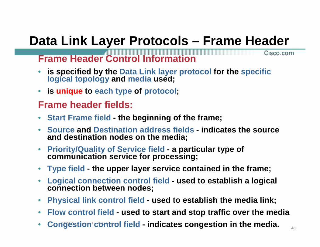
Data Link Layer Protocols – Frame HeaderFrame Header Control Information• is specified by the Data Link layer protocol for the specific
logical topology and media used;• is unique to each type of protocol;
Frame header fields:• Start Frame field - the beginning of the frame;• Source and Destination address fields - indicates the source
and destination nodes on the media;• Priority/Quality of Service field - a particular type of
communication service for processing;• Type field - the upper layer service contained in the frame;• Logical connection control field - used to establish a logical
connection between nodes; • Physical link control field - used to establish the media link; • Flow control field - used to start and stop traffic over the media• Congestion control field - indicates congestion in the media.

444444© 2004, Cisco Systems, Inc. All rights reserved.
Data Link Layer Protocols – Frame HeaderData Link Layer Frame Header Structure

454545© 2004, Cisco Systems, Inc. All rights reserved.
Data Link Layer Addressing
Data Link Layer Addressing• is used in transporting the frame across the shared local media;• device addresses are referred to as physical addresses;• is contained within the frame header;• frame header specifies the frame destinationnode on the local network and contain the source address of the frame;• physical addresses do not indicate on what network the device is located;• is only used for local delivery and have nomeaning beyond the local network.

464646© 2004, Cisco Systems, Inc. All rights reserved.
Data Link Layer Addressing
Data Link layer addressing depends on the logical topology
Addressing Requirements
• Point-to-point topology - do notrequire addressing;
• Ring and Multi-access topologies - addressing is required.

474747© 2004, Cisco Systems, Inc. All rights reserved.
Data Link Layer Protocols – Frame Trailer
Frame Trailer• is add by the Data Link layer protocols to the end of each frame;
• is used to determine if the frame arrived without error.
Error Detection• the process of determination of frame errors;
• is different from error correction;
• is accomplished by placing a logical or mathematical summary of the bits that comprise the frame in the trailer.

484848© 2004, Cisco Systems, Inc. All rights reserved.
Data Link Layer Protocols – Frame Trailer
Frame Check Sequence (FCS) field:• is used to determine if errors occurred in the transmission and reception of the frame;• the error detection mechanism provided by the use of the FCS field discovers most errors caused on the media;Cyclic Redundancy Check (CRC) value:• created by the transmitting node as a logical summary of the contents of the frame;• is placed in the Frame Check Sequence(FCS) field of the frame to represent the contents of the frame.

494949© 2004, Cisco Systems, Inc. All rights reserved.
Data Link Layer Protocols – Frame Trailer
Receiving node:• calculates its own logical summary, or CRC, of the frame (when the frame arrives at the destination node);• compares the two CRC values:
- if the two values are the same, the frame is considered to have arrived as transmitted;
- if the CRC value in the FCS differs from the CRC calculated at the receiving node, the frame is discarded.

505050© 2004, Cisco Systems, Inc. All rights reserved.
Data Link Layer Protocols – Frame Trailer
Frame Trailer Fields – FCS, Stop Frame

515151© 2004, Cisco Systems, Inc. All rights reserved.
Data Link Layer ProtocolsData Link Layer Protocols – LAN and WAN Technology
Layer 2 Protocols:• Ethernet • Point-to-Point Protocol(PPP) • High-Level Data Link Control (HDLC)• Frame Relay• Asynchronous Transfer Mode (ATM)

525252© 2004, Cisco Systems, Inc. All rights reserved.
Ethernet Protocols for LANsEthernet Protocol for LANsEthernet• is a family of networking technologies that are defined in the
IEEE 802.2 and 802.3 standards;• defines both the Layer 2 protocols and the Layer 1 technologies;• is the most widely used LAN technology and supports data
bandwidths of 10, 100, 1000, or 10,000 Mbps; • the basic frame format and the IEEE sublayers of OSI Layers 1
and 2 remain consistent across all forms of Ethernet;• provides unacknowledged connectionless service over a shared
media using CSMA/CD as the media access method;MAC address • shared media requires that the Ethernet packet header use a
Data Link layer address to identify the source and destination nodes;
• is 48 bits and is generally represented in hexadecimal format.

535353© 2004, Cisco Systems, Inc. All rights reserved.
Ethernet Protocols for LANsEthernet Protocols for LANs

545454© 2004, Cisco Systems, Inc. All rights reserved.
Point to Point Protocol for WANsPoint to Point Protocol (PPP) for WANs• is a protocol used to deliver frames between two nodes;• PPP standard is defined by RFCs;• was developed as a WAN protocol and remains the protocol of
choice to implement many serial WANs;• can be used on various physical media - twisted pair, fiber optic
lines, and satellite transmission, as well as for virtual connections. • uses a layered architecture.PPP session• establishes logical connections between two nodes;• hides the underlying physical media from the upper PPP protocol;• provide PPP with a method for encapsulating multiple protocols
over a point-to-point link;• each protocol encapsulated over the link establishes its own PPP
session; • PPP allows the two nodes to negotiate options within the PPP
session. This includes authentication, compression, and multilink (the use of multiple physical connections).

555555© 2004, Cisco Systems, Inc. All rights reserved.
Point to Point Protocol for WANsPoint to Point Protocol - Data Link Layer Protocol for WANs

565656© 2004, Cisco Systems, Inc. All rights reserved.
Wireless Protocol for LANs
Wireless Protocol for LANs802.11• is an extension of the IEEE 802 standards;• uses the same 802.2 LLC and 48-bit addressing
scheme as other 802 LANs;Standard IEEE 802.11• commonly referred to as Wi-Fi;• is a contention-based system using a Carrier
Sense Multiple Access/Collision Avoidance (CSMA/CA) media access process;
• other services are authentication, association(connectivity to a wireless device), and privacy(encryption).

575757© 2004, Cisco Systems, Inc. All rights reserved.
Wireless Protocol for LANsCSMA/CA• specifies a random backoff procedure for all nodes
that are waiting to transmit;• the most likely opportunity for medium contention
is just after the medium becomes available. Making the nodes back off for a random periodgreatly reduces the likelihood of a collision;
802.11 networks:• use Data Link acknowledgements to confirm that a
frame is received successfully;• if the sending station does not detect the
acknowledgement frame (either because the original data frame or the acknowledgment was not received intact) the frame is retransmitted;
• the explicit acknowledgement overcomesinterference and other radio-related problems.

585858© 2004, Cisco Systems, Inc. All rights reserved.
Wireless Protocol for LANs802.11 frame fields:• Protocol Version field - version of 802.11 frame in use;• Type and Subtype fields - Identifies one of three functions and sub
functions of the frame: control, data, and management• To DS field - Set to 1 in data frames destined for the distribution
system (devices in the wireless structure)• From DS field - Set to 1 in data frames exiting the distribution system• More Fragments field - Set to 1 for frames that have another fragment • Retry field - Set to 1 if the frame is a retransmission of an earlier
frame• Power Management field - Set to 1 to indicate that a node will be in
power-save mode• More Data field - Set to 1 to indicate to a node in power-save mode
that more frames are buffered for that node• Wired Equivalent Privacy (WEP) field - Set to 1 if the frame contains
WEP encrypted information for security• Order field - Set to 1 in a data type frame that uses Strictly Ordered
service class (does not need reordering)

595959© 2004, Cisco Systems, Inc. All rights reserved.
Wireless Protocol for LANs802.11 frame fields:• Duration/ID field - Depending on the type of frame, represents either
the time (in microseconds), required to transmit the frame or an association identity (AID) for the station that transmitted the frame;
• Destination Address (DA) field - MAC address of the final destination node in the network;
• Source Address (SA) field - MAC address of the node the initiated the frame;
• Receiver Address (RA) field - MAC address that identifies the wireless device that is the immediate recipient of the frame;
• Transmitter Address (TA) field - MAC address that identifies the wireless device that transmitted the frame;
• Sequence Number field – a sequence number assigned to the frame;retransmitted frames are identified by duplicate sequence numbers;
• Fragment Number field – a number for each fragment of a frame;• Frame Body field - Contains the information being transported; for
data frames, typically an IP packet• FCS field - Contains a 32-bit cyclic redundancy check (CRC) of the
frame

606060© 2004, Cisco Systems, Inc. All rights reserved.
Wireless Protocol for LANsWireless Protocol for LANs
616161© 2004, Cisco Systems, Inc. All rights reserved.
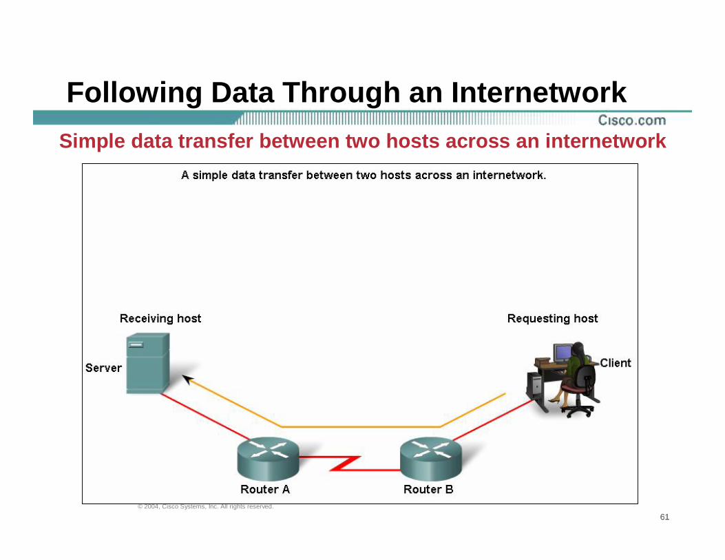
Following Data Through an InternetworkSimple data transfer between two hosts across an internetwork

626262© 2004, Cisco Systems, Inc. All rights reserved.
Following Data Through an InternetworkSimple data transfer between two hosts across an internetwork
1
636363© 2004, Cisco Systems, Inc. All rights reserved.
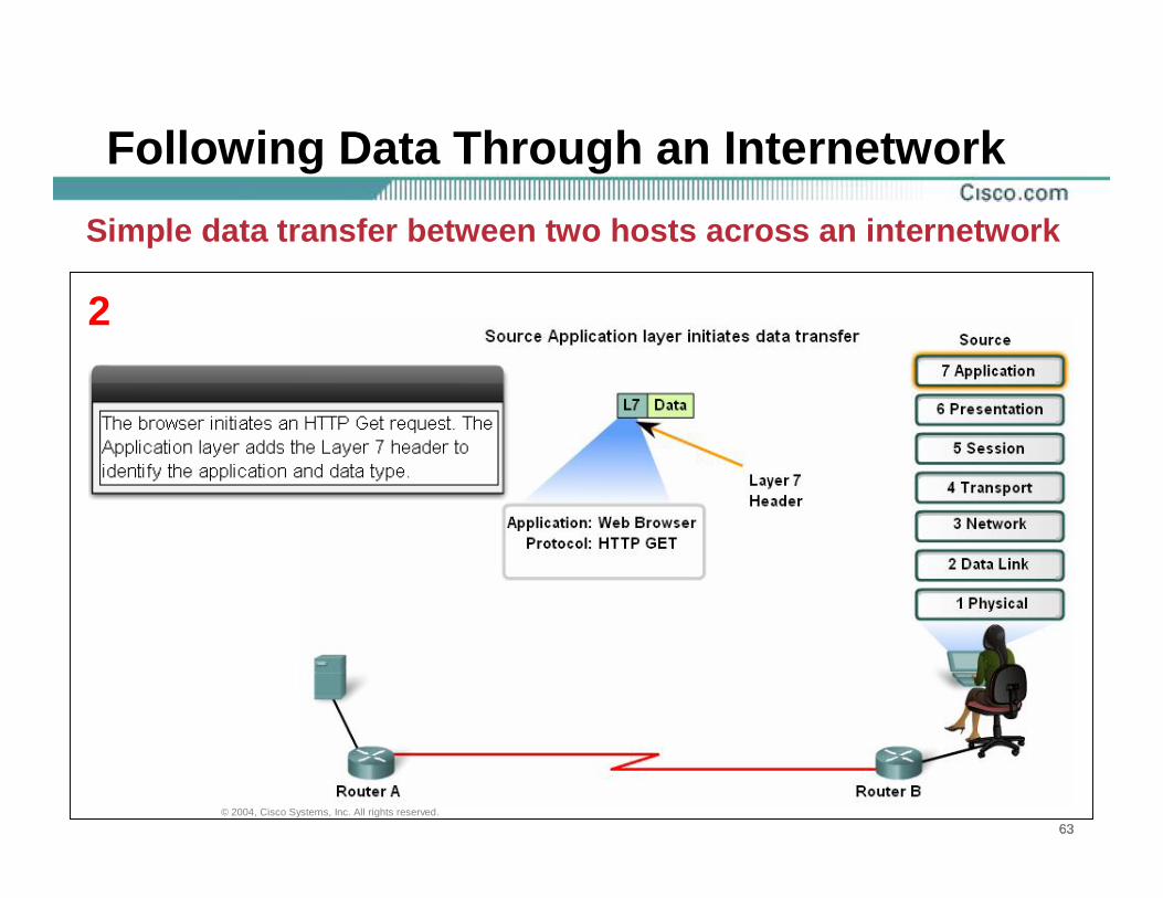
Following Data Through an InternetworkSimple data transfer between two hosts across an internetwork
2

646464© 2004, Cisco Systems, Inc. All rights reserved.
Following Data Through an InternetworkSimple data transfer between two hosts across an internetwork
3

656565© 2004, Cisco Systems, Inc. All rights reserved.
Following Data Through an InternetworkSimple data transfer between two hosts across an internetwork
4

666666© 2004, Cisco Systems, Inc. All rights reserved.
Following Data Through an InternetworkSimple data transfer between two hosts across an internetwork
5

676767© 2004, Cisco Systems, Inc. All rights reserved.
Following Data Through an InternetworkSimple data transfer between two hosts across an internetwork
6

686868© 2004, Cisco Systems, Inc. All rights reserved.
Following Data Through an InternetworkSimple data transfer between two hosts across an internetwork
7

696969© 2004, Cisco Systems, Inc. All rights reserved.
Following Data Through an InternetworkSimple data transfer between two hosts across an internetwork
8

707070© 2004, Cisco Systems, Inc. All rights reserved.
Following Data Through an InternetworkSimple data transfer between two hosts across an internetwork
9

717171© 2004, Cisco Systems, Inc. All rights reserved.
Following Data Through an InternetworkSimple data transfer between two hosts across an internetwork
10

727272© 2004, Cisco Systems, Inc. All rights reserved.
Following Data Through an InternetworkSimple data transfer between two hosts across an internetwork
11

737373© 2004, Cisco Systems, Inc. All rights reserved.
Following Data Through an InternetworkSimple data transfer between two hosts across an internetwork
12

747474© 2004, Cisco Systems, Inc. All rights reserved.
Following Data Through an InternetworkSimple data transfer between two hosts across an internetwork
13

757575© 2004, Cisco Systems, Inc. All rights reserved.
Following Data Through an InternetworkSimple data transfer between two hosts across an internetwork
14

767676© 2004, Cisco Systems, Inc. All rights reserved.
Following Data Through an InternetworkSimple data transfer between two hosts across an internetwork
15

777777© 2004, Cisco Systems, Inc. All rights reserved.
Following Data Through an InternetworkSimple data transfer between two hosts across an internetwork
16

787878© 2004, Cisco Systems, Inc. All rights reserved.
Following Data Through an InternetworkSimple data transfer between two hosts across an internetwork
17

797979© 2004, Cisco Systems, Inc. All rights reserved.
Following Data Through an InternetworkSimple data transfer between two hosts across an internetwork
18

808080© 2004, Cisco Systems, Inc. All rights reserved.
Following Data Through an InternetworkSimple data transfer between two hosts across an internetwork
19

818181© 2004, Cisco Systems, Inc. All rights reserved.
Following Data Through an InternetworkSimple data transfer between two hosts across an internetwork
20

828282© 2004, Cisco Systems, Inc. All rights reserved.
Following Data Through an InternetworkSimple data transfer between two hosts across an internetwork
21

838383© 2004, Cisco Systems, Inc. All rights reserved.
Following Data Through an InternetworkSimple data transfer between two hosts across an internetwork
22

848484© 2004, Cisco Systems, Inc. All rights reserved.
Summary

© 2004, Cisco Systems, Inc. All rights reserved.