caution: this document contains mixed page sizes (8.5 …n0nas/manuals/onan/184-0169 onan grca...
TRANSCRIPT

Caution: This document contains mixed page sizes (8.5 x 11 or 11 x 17), which may affect printing. Please adjust your printer settings
according to the size of each page you wish to print.

Printed in U. S. A.
Installation ManualGRCA
184-0169May, 2004


Page 1 of 7
Supplement 965−1081Date: 12-2004Insert with-
Titles: GRCA Installation ManualGRCA Service Manual
Numbers: 184−0169, dated May, 2004184−0177, dated July, 2004
This supplement updates the GRCA Installation Manual and GRCA Service Manual to include infor-mation on the RSZ transfer switch time delay relay.
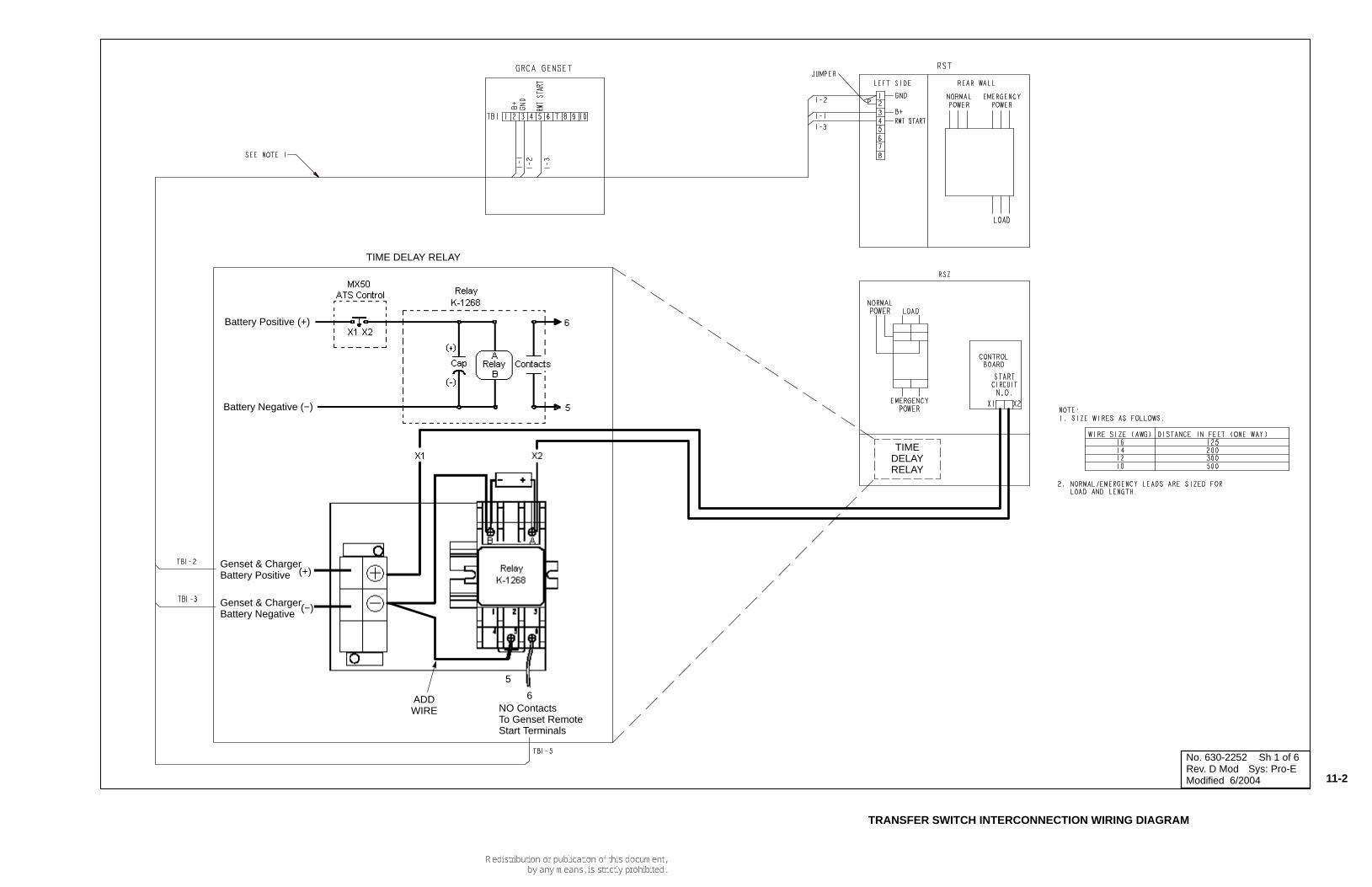
TIME DELAY RELAY
Beginning in April of 2004, GRCA generatorsets include a transfer switch time delay relay.
This relay eliminated a loss of start signal thatsometimes occured on earlier models duringtransfer from normal to emergency power.Without this relay, the genset may not start ascommanded during a loss of power or whentesting the transfer switch.
If your genset does not include this relay, kit307−3040 can be purchased separately.
NOTE: The wiring diagram provided with thetransfer switch shows connections ofthis relay to a genset, incorrectly indi-cating that terminals 1 and 5 are nor-mally open contacts. As shown in theillustrations, the normally open con-tacts are terminals 5 and 6.
CHANGES TO MANUALS
GRCA Installation Manual (184−0169) − Replace Figures 7-3, 7-4, 7-5, and 7-6 with the attachedpages.
GRCA Service Manual (184−0177) − Replace page 11-2 with the attached page.

Page 2 of 7

7-3
No. 306-4692 Sh 2 of 2Rev. C Mod Sys: Pro-EModified 7/2004
WITH TIME DELAY RELAY
FIGURE 7-3. RSZ 100-AMP NEMA-1 TRANSFER SWITCH

7-4
No. 306-4693 Sh 2 of 2Rev. C Mod Sys: Pro-EModified 7/2004
WITH TIME DELAY RELAY
RSZ 200-AMP NEMA-1 TRANSFER SWITCH

7-5
No. 306-4694 Sh 2 of 2Rev. C Mod Sys: Pro-EModified 7/2004
WITH TIME DELAY RELAY
RSZ 100-AMP NEMA-3R TRANSFER SWITCH

7-6
No. 306-4695 Sh 2 of 2Rev. C Mod Sys: Pro-EModified 7/2004
WITH TIME DELAY RELAY
RSZ 200-AMP NEMA-3R TRANSFER SWITCH
No. 630-2252 Sh 1 of 6Rev. D Mod Sys: Pro-EModified 6/2004
TIME DELAY RELAY
TIMEDELAYRELAY
ADDWIRE
5
NO ContactsTo Genset RemoteStart Terminals
6
Battery Positive (+)
Battery Negative (−)
Genset & ChargerBattery Positive (+)
Genset & ChargerBattery Negative
(−)
TRANSFER SWITCH INTERCONNECTION WIRING DIAGRAM
11-2

Table of Contents
i
TITLE PAGE
SAFETY PRECAUTIONS . . . . . . . . . . . . . . . . . . . . . . . . . . . . . . . . . . . . . . . . . . . . . . . . iii
1. INTRODUCTION . . . . . . . . . . . . . . . . . . . . . . . . . . . . . . . . . . . . . . . . . . . . . . . . . . . 1-1
About this Manual . . . . . . . . . . . . . . . . . . . . . . . . . . . . . . . . . . . . . . . . . . . . . . . 1-1
Pre-Installation Considerations . . . . . . . . . . . . . . . . . . . . . . . . . . . . . . . . . . . . . 1-1
Installation Overview . . . . . . . . . . . . . . . . . . . . . . . . . . . . . . . . . . . . . . . . . . . . 1-2
Installation Codes and Safety Recommendations . . . . . . . . . . . . . . . . . . . . . . 1-2
2. STEP-BY-STEP INSTALLATION OUTLINE . . . . . . . . . . . . . . . . . . . . . . . . . . . . . . 2-1
Introduction . . . . . . . . . . . . . . . . . . . . . . . . . . . . . . . . . . . . . . . . . . . . . . . . . . . . 2-1
Locating the Site . . . . . . . . . . . . . . . . . . . . . . . . . . . . . . . . . . . . . . . . . . . . . . . . 2-1
Genset Clearances . . . . . . . . . . . . . . . . . . . . . . . . . . . . . . . . . . . . . . . . . . . . . . 2-2
Preparing the Site . . . . . . . . . . . . . . . . . . . . . . . . . . . . . . . . . . . . . . . . . . . . . . . 2-2
Moving the Genset . . . . . . . . . . . . . . . . . . . . . . . . . . . . . . . . . . . . . . . . . . . . . . 2-3
Placing the Genset . . . . . . . . . . . . . . . . . . . . . . . . . . . . . . . . . . . . . . . . . . . . . . 2-4
Connecting the Genset . . . . . . . . . . . . . . . . . . . . . . . . . . . . . . . . . . . . . . . . . . . 2-5
3. MECHANICAL . . . . . . . . . . . . . . . . . . . . . . . . . . . . . . . . . . . . . . . . . . . . . . . . . . . . . 3-1
Location . . . . . . . . . . . . . . . . . . . . . . . . . . . . . . . . . . . . . . . . . . . . . . . . . . . . . . 3-1
Access and Mounting . . . . . . . . . . . . . . . . . . . . . . . . . . . . . . . . . . . . . . . . . . . . 3-1
Engine Exhaust . . . . . . . . . . . . . . . . . . . . . . . . . . . . . . . . . . . . . . . . . . . . . . . . 3-2
Fuel System . . . . . . . . . . . . . . . . . . . . . . . . . . . . . . . . . . . . . . . . . . . . . . . . . . . 3-2
Natural Gas Fuel System . . . . . . . . . . . . . . . . . . . . . . . . . . . . . . . . . . . . . . . . . 3-3
LP Vapor Fuel System . . . . . . . . . . . . . . . . . . . . . . . . . . . . . . . . . . . . . . . . . . . 3-4
4. ELECTRICAL CONNECTIONS . . . . . . . . . . . . . . . . . . . . . . . . . . . . . . . . . . . . . . . . 4-1
Conduit . . . . . . . . . . . . . . . . . . . . . . . . . . . . . . . . . . . . . . . . . . . . . . . . . . . . . . . 4-1
Control and Power Connections . . . . . . . . . . . . . . . . . . . . . . . . . . . . . . . . . . . . 4-1
Grounding . . . . . . . . . . . . . . . . . . . . . . . . . . . . . . . . . . . . . . . . . . . . . . . . . . . . . 4-3
Transfer Switch . . . . . . . . . . . . . . . . . . . . . . . . . . . . . . . . . . . . . . . . . . . . . . . . . 4-4
Battery . . . . . . . . . . . . . . . . . . . . . . . . . . . . . . . . . . . . . . . . . . . . . . . . . . . . . . . 4-8
5. INSTALLATION REVIEW AND STARTUP . . . . . . . . . . . . . . . . . . . . . . . . . . . . . . . 5-1
Installation Review . . . . . . . . . . . . . . . . . . . . . . . . . . . . . . . . . . . . . . . . . . . . . . 5-1
Startup . . . . . . . . . . . . . . . . . . . . . . . . . . . . . . . . . . . . . . . . . . . . . . . . . . . . . . . 5-1
6. SPECIFICATIONS . . . . . . . . . . . . . . . . . . . . . . . . . . . . . . . . . . . . . . . . . . . . . . . . . . 6-1

7. DRAWINGS . . . . . . . . . . . . . . . . . . . . . . . . . . . . . . . . . . . . . . . . . . . . . . . . . . . . . . . 7-1
GRCA Genset Outline Drawing . . . . . . . . . . . . . . . . . . . . . . . . . . . . . . . . . . . . .7-1
GRCA Wiring Diagram . . . . . . . . . . . . . . . . . . . . . . . . . . . . . . . . . . . . . . . . . . . .7-2
RST Transfer Switch Drawings . . . . . . . . . . . . . . . . . . . . . . . . . . . . . . . . . . . . .7-3
ii

Thoroughly read the OPERATOR’S MANUALbefore operating the genset. Safe operationand top performance can be obtained onlywhen equipment is operated and maintainedproperly.
The following symbols in this manual alert you topotential hazards to the operator, service personand equipment.
alerts you to an immediate hazardwhich will result in severe personal injury ordeath.
alerts you to a hazard or unsafepractice which can result in severe personalinjury or death.
alerts you to a hazard or unsafepractice which can result in personal injury orequipment damage.
Electricity, fuel, exhaust, batteries and movingparts present hazards which can result in severepersonal injury or death.
GENERAL PRECAUTIONS
• Keep ABC fire extinguishers handy.
• Make sure all fasteners are secure andtorqued properly.
• Keep the genset and its compartment clean.Excess oil and oily rags can catch fire. Dirtand gear stowed in the compartment canrestrict cooling air.
• Before working on the genset, disconnect thenegative (–) battery cable at the battery toprevent starting.
• Use caution when making adjustments whilethe genset is running—hot, moving or electri-cally live parts can cause severe personalinjury or death.
• Used engine oil has been identified by somestate and federal agencies as causing cancer
or reproductive toxicity. Do not ingest, inhale,or contact used oil or its vapors.
• Do not work on the genset when mentally orphysically fatigued or after consuming alco-hol or drugs.
• Carefully follow all applicable local, state andfederal codes.
GENERATOR VOLTAGE IS DEADLY!
• Generator output connections must be madeby a qualified electrician in accordance withapplicable codes.
• The genset must not be connected to thepublic utility or any other source of electricalpower. Connection could lead to electrocu-tion of utility workers and damage to equip-ment. An approved switching device must beused to prevent interconnections.
• Use caution when working on live electricalequipment. Remove jewelry, make sureclothing and shoes are dry and stand on adry wooden platform.
FUEL IS FLAMMABLE AND EXPLOSIVE
• Keep flames, cigarettes, sparks, pilot lights,electrical arc-producing equipment andswitches and all other sources of ignition wellaway from areas where fuel fumes are pres-ent and areas sharing ventilation.
• Fuel lines must be secured, free of leaks andseparated or shielded from electrical wiring.
• Leaks can lead to explosive accumulations ofgas. Natural gas rises when released andcan accumulate under hoods and insidehousings and buildings. LPG sinks whenreleased and can accumulate inside hous-ings and basements and other below–gradespaces. Prevent leaks and the accumulationof gas.
iii
▲ DANGER!
▲WARNING!
▲CAUTION!
IMPORTANT SAFETY INSTRUCTIONSSAVE THESE INSTRUCTIONS - This manual contains important instructions thatshould be followed during installation and maintenance of the generator and battery.

ENGINE EXHAUST IS DEADLY!
• Learn the symptoms of carbon monoxide poi-soning in this manual.
• The exhaust system must be installed inaccordance with the genset InstallationManual.
• Do not use engine cooling air to heat a roomor compartment.
• Make sure there is ample fresh air whenoperating the genset in a confined area.
BATTERY PRECAUTIONS
Battery Gas Is Explosive!
• When replacing batteries use the same num-ber and the following type battery: Group 26.
• Do not dispose of battery orbatteries in a fire. The battery is capableof exploding.
• Do not open or mutilate thebattery or batteries. Released electrolytehas ben known to be harmful to the skinand eyes and to be toxic.
• A battery presents a risk ofelectrical shock and high short circuitcurrent. The following precautions are tobe observed when working on batteries.(1) Remove watches, rings, or othermetal objects.(2) Use tools with insulated handles.
• The electrolyte is a dilute sul-furic acid that is harmful to the skin andeyes. It is electrically conductive andcorrosive. The following procedures are tobe observed:(1) Wear full eye protection and protective
clothing,(2) Where electrolyte contacts the skin,
wash it off immediately with water and
seek medical attention, and(3) Where electrolyte contacts the eyes,
flush thoroughly and immediately with water and seek medical attention, and
(4) Spilled electrolyte is to be washed down with an acid neutralizing agent. A common practice is to use a solution of onepound (500 grams) bicarbonate of soda to one gallon (4 liters) of water. Thebicarbonate of sods solution is to beadded until the evidence of reaction(foaming) has ceased. The resultingliquid is to be flushed with water and thearea dried.
• Lead acid batteries presenta risk of fire because they generatehydrogen gas. The following proceduresare to be followed:(1) DO NOT SMOKE when near batteries.(2) DO NOT cause flame or spark in battery
area, and(3) Discharge static electricity from body
before touching batteries by first touching a grounded metal surface.
• When disconnecting the battery cables,always check for a battery charger and dis-connect it first then disconnect the negative(-) battery cable.
• When reconnecting battery cables, alwaysreconnect the negative (-) battery cable afterthe positive (+) cable, then reconnect the bat-tery charger to reduce arcing.
MOVING PARTS CAN CAUSE SEVEREPERSONAL INJURY OR DEATH
• Do not wear loose clothing or jewelry nearmoving parts such as fans.
• Keep hands away from moving parts.
• Keep guards in place over fans.
iv
▲CAUTION!
▲CAUTION!
▲CAUTION!
▲CAUTION!
▲CAUTION!

1. Where can I find field wiring data on this unit? It it covered by Section 7 of the Installation Manual.
2. Where can I find explanations of all symbols used in this manual? Refer toPage iii.
3. Where can I find the circuit breaker used with this unit? A 2-Pole 50 Ampcircuit breaker is an intergral part of the Genset located in the main controlpanel.
4. At what temperature range can the unit run at? The Genset is designed to run from 00 to 1100 F.
5. What are the electrical ratings for this unit? Refer to Installation Section 6-1.
6. What is the electrical Phase Configuration of the unit? Single Phase - 3 Wire120/240v, refer to Installation Section 6-1.
7. What is the fuel connection type, pressure and flow of the unit? SeeInstallation Sections 6-1, and 3-2 to 3-5.
8. Where can I find exhaust connection and muffler part numbers for the unit?Refer to Installation Section 3-2.
9. Where are the ground connection instructions? See Installation Section 4-3.
10. Where can I find instructions on the fuses the unit uses? See InstallationSection 4-1.
11. What voltage is the battery rated at? See Installation Section 4-6 and 6-1.
12. What is the minimum cold cranking amperage rating of the batteries? SeeInstallation Section 6-1.
13. How do I remove and replace the battery? See Installation Section 4-8 andOperator’s Section 3-7.
v
Safety Informational Data

ABOUT THIS MANUALThis manual is a guide for the installation of theSeries GRCA generator sets (gensets). The Step-by-Step Installation Outline section provides anoverview of the basic installation steps. TheMechanical and Electrical Connections sectionscover most aspects of the installation procedures.The Installation Review and Startup section cov-ers the steps necessary to place the genset inservice. Specifications tabulates features of thegenset important for installation, operation andmaintenance. Refer to the model-specific OutlineDrawing, Specification Bulletin and Data Sheetfor more information.
This manual covers two specs of GRCA gensets:• GRCA, Natural Gas• GRCA, LP Vapor (requires conversion)
See the Operator’s Manual for operation andmaintenance and refer to the Service Manual forservice procedures.
PRE–INSTALLATION CONSIDERATIONSThe exhaust from this genset contains carbonmonoxide. Do not install this genset inside abuilding or where exhaust can be drawn into oraccumulate in an inhabitable area.
Consider the following factors to determinewhether the location is suitable for the gensetinstallation.
• Install on compacted ground leveled with alayer of sand or pea gravel.
• Place near electric service to house.
• Place near fuel source.
• Orient so that prevailing winds carry exhaustaway from occupied areas.
• Before installing, call for local utilities to markthe location of buried utility services (electric,gas, telephone, etc.).
• For natural gas installations, verify that theexisting meter supplies gas at adequatepressure and flow rate. At full load, the
genset requires 239,000 BTU/hr. If you usenatural gas for any other purpose, you mustconsider the total of the genset and house-hold use. For example, a typical installationat a residence with other gas applianceswould need a 420,000 BTU meter. Thiswould require 659,000 BTU/hr. capability fora typical household.
• Provide adequate fresh air for the engine.Allow sufficient air flow for cooling and venti-lation. Figure 1–1 shows airflow patternsthrough the genset.
Do not locate the genset in aconfined area such as in a three–sidedniche of a building. Insufficient air flowthrough the genset housing can causethe genset to overheat and shut downresulting in a loss of standby electricalpower.
• Locate away from noise sensitive areas suchas bedrooms, living room windows, andneighbors.
• Secure from vandalism, flooding, and vehic-ular traffic.
• Locate away from possible obstructions toventilation caused by snow drifts, plantgrowth, lawn clippings, falling leaves, etc.
FIGURE 1-1. GENSET AIRFLOW
1-1
1. Introduction
▲CAUTION!

INSTALLATION OVERVIEW
Proper application and installation are essentialfor reliability and safety.
Installation: The proper installation of the gensetand all the other equipment included in the stand-by power system requires the skill of qualifiedpersonnel such as electricians, mechanics andplumbers. Call an authorized Cummins/Onandealer or distributor if questions remain.
Reliability and Safety: It is essential for reliabili-ty and safety that these instructions be followedclosely and that the standby system, as a whole,complies with all applicable codes at the time it isplaced in service.
Improper application or installa-tion can result in severe personal injury ordeath and property damage. Installation mustbe made by qualified electrical and mechani-cal technicians. The standby power systemmust comply with all applicable codes.
IMPORTANT NOTICE: Depending on the locationof the genset and its use, it may be necessary toobtain an air quality emissions permit before
installation begins. Check with the local pollutioncontrol or air quality authority.
INSTALLATION CODES AND SAFETYRECOMMENDATIONS
The following list of Installation Codes and SafetyRecommendations applies to the installation andoperation of standby gensets. This list is for refer-ence only and not intended to be inclusive of allapplicable codes and standards. The address ofeach agency is listed so that copies of the codesmay be obtained for reference. Installation codesand recommendations are subject to change, andmay vary by location or over time. The gensetinstaller bears sole responsibility for following allapplicable local codes and regulations.
This manual contains information that is subject tochange. For this reason, use only the installationmanual supplied with the genset for the installation.
Incorrect installation, service, orreplacement of parts can result in severe per-sonal injury, death and/or equipment damage.Service personnel must be qualified to per-form electrical and/or mechanical componentinstallation.
1-2
TABLE 1–1. INSTALLATION CODES AND SAFETY RECOMMENDATIONS
NFPA 70 National Electric CodeNFPA 37 Installation and Use of Stationary Combustion
Engines and Gas Turbines
NFPA 54 National Fuel Gas Code
NFPA 58 Storage and Handling of Liquefied PetroleumGases
CSA Electrical BulletinCSA C22.2 No. 100CSA C22.2 No. 14
California Administrative Code – Title 25 Chapter 3
Underwriters LaboratoriesUL2200 Stationary Engine Generator Assemblies
National Fire Protection Association,470 Atlantic AvenueBoston, MA 02210
Canadian Standards Association,Housing and Construction Materials Section178 Rexdale Blvd.Rexdale, Ontario, Canada M9W 1R3
State of CaliforniaDocuments SectionP.O. Box 1015North Highlands, CA 95660
Underwriters Laboratories, Inc.3333 Pfingsten RoadNorthbrook, IL 60062–2096
▲WARNING!
▲WARNING!

INTRODUCTION
This section is a step-by-step overview of a typi-cal installation. This section includes:
• Locating the site
• Genset Clearances
• Preparing the site
• Moving the genset
• Placing the genset
• Connecting the genset
Review this section, then refer to the detailedinstructions that are given in the following sec-
tions for specific procedures and important safetyprecautions before starting the installation. Theinstaller is responsible for complying with all appli-cable installation codes and safety requirements.
LOCATING THE SITE
These gensets are housed in a weather-protec-tive enclosure for installation out-of-doors.
Choose a site close to the electric service andfuel supply lines (Natural Gas) or tanks (LPVapor). Figure 2–1 shows a typical natural gasinstallation. The main distribution, transfer switchand sub-panels are inside the house.
2-1
2. Step-by-Step Installation Outline
FIGURE 2–1. TYPICAL GENSET SITE
ElectricDisconnect
gasmeter
gasshutoffvalve
Electricmeter
Maindistribution
panel
transferswitch
sub-panel
Undergroundgas service
undergroundelectric service

GENSET CLEARANCES
The genset must be a minimum of 3 ft (915 mm)from combustible material (NFPA 37). Leave atleast 3 ft (915 mm) all around the genset enclo-sure for access to the inside (NEC Art. 110–26a,Art. 110–26b). The genset must be at least 5 ft(1524 mm) from any opening (window, door, vent,etc.) in the wall, and the exhaust must not be ableto accumulate in any occupied area (See Figure2–2).
PREPARING THE SITE
If the site is not on level ground prepare an arealarge enough to easily hold the genset so that itcan be mounted level. If you add fill to the site, besure to tamp the ground until it is firm and stabilized.
Prepare a site at least 45 in by 34 in (1143 mm by864 mm) on firm ground. Sites on inclines require
more area. Add a layer of sand or pea graveldeep enough so that you can level the genset.See Figure 2–3.
Install the rigid fuel line, manual fuel shut-offvalve, electrical disconnect, (See Mechanical andElectrical section for details) and the waterproofelectrical conduit to the site (See Mechanical sec-tion for details).
2-2
FIGURE 2–2. GENSET CLEARANCES
5 ft (1524 mm) Min to any opening
FIGURE 2–3. LEVELING THE GENSET

2-3
MOVING THE GENSET
The genset is heavy [575 lbs (261 kg)], and mustbe handled with care. Carefully raise the gensetwith a forklift or crane. Make sure the unit is sta-ble before moving it into position for installation.See Figures 2–4 and 2–5.
The genset weighs 575 lb. (261 kg).Dropping the genset can cause severe per-sonal injury or death. Keep feet and handsclear when lifting the genset.
Use a fork lift truck to move the genset to the siteyou prepared. The genset base has fork lift chan-nels. Orient the genset so that the access open-ing for the control is opposite from the buildingand exhaust is pointed away from windows,doors, vents, and habitable areas.
The genset can be transported and moved to thesite in a small tilt-bed trailer. At the site, the gensetcan be carefully slid from the trailer to the groundwhen the bed is tilted. See Figure 2–6
The genset is shipped with oil inthe crankcase. Do not tip the genset on itsside.
FIGURE 2–4. MOVING THE GENSET INTOPOSITION
FIGURE 2–5. LIFTING STRAPS
FIGURE 2–6. TILT–BED TRAILER
▲WARNING!
▲CAUTION!

PLACING THE GENSET
Remove the plastic bag covering the genset andcollect loose shipped items, such as theOperator’s Manual.
While the genset is raised, install the tabs to thefour corners of the base. Use the cap screws andwashers supplied to secure the tabs to the base.The tabs have weld–nuts on the bottom. The tabscan be turned 90 degrees. See Figure 2–7.
Place the genset in position at the prepared siteon the ground. Pound the four spikes into theground to fix the genset in place. Do not poundthe spikes into any wires or pipes.
Pounding the spikes into electric,gas, or telephone service lines can result insevere personal injury or death. Observe theutility company markings.
2-4
▲WARNING!
FIGURE 2–7. CORNER TABS
mountingTAB
MountingTab

CONNECTING THE GENSET
Fuel Lines
Fuel presents the hazard of fire orexplosion that can result in severe personalinjury or death. Do not smoke or allow anyflame, spark, pilot light, or other ignitionsources near fuel or in the installation area.Read the important safety precautions in theFuel System section.
Connect the flexible fuel line included (See FuelSystem in Section 3) between the 3/4 NPT fittingon the genset and the fuel supply line. See Figure2–8.
Electrical Lines
Thread the flexible liquid-tight conduits throughthe electrical stub-up area in the skid base andconnect the clamp on the conduit to the bottom ofthe genset control box. The control has two holesfor conduit on its bottom. See Figure 2–9.
The outline drawing, Figure 7–1, shows alternateconduit access areas on the sides of the enclo-sure. Use these areas for entry into the enclosurewhen underground access is not practical. Theinstaller is responsible for complying with all localcodes.
Route the wires from the transfer switch, batterycharger, and battery pad heater through the con-duit and connect the wires to the mating terminalson TB1 in the genset control box.
Refer to each of the sections in this manual fordetailed installation instructions and for importantsafety precautions. Always follow the proceduresin the Initial Start and Checks section when theinstallation is complete.
2-5
▲WARNING!
FLEXIBLEfuel line
gensetfuel fitting
control box
FIGURE 2–9. ELECTRICAL CONNECTION
FIGURE 2–8. FUEL CONNECTION

LOCATION
These gensets are designed for installation out-of-doors in its weather-protective enclosure.
Factors to consider when deciding where tolocate the genset include:
• Proximity of genset, transfer switch, loadsand fuel supply lines (Natural Gas) or tanks(LPG).
• Access for maintenance and service.
• Security from vandalism, flooding and vehic-ular traffic.
• Noise levels and proximity of property lines.
• Away from gutter wash and roof dripping.
• Safe dispersal of engine exhaust and coolingair away from buildings, habitable areas, andpeople.
• Possible obstructions to ventilation causedby snowdrifts, plant growth, lawn clippings,falling leaves, etc.
• See Locating the Site in Section 2.
ACCESS AND MOUNTING
The genset requires 3 ft (915 mm) minimumaccess space on all sides for servicing. SeeFigure 3–1.
3-1
3. Mechanical
FIGURE 3–1. GENSET ACCESS FOR MAINTENANCE

ENGINE EXHAUST
The exhaust system of this genset was designedfor this engine and is complete. Do not modify oradd to the exhaust system of this genset.
EXHAUST GAS IS DEADLY! Theexhaust system must terminate away frombuilding vents, windows and doors and shel-tered spaces that may not have ample freshair ventilation.
Do not use genset discharge air or engineexhaust for heating a room or enclosed space.
Engine discharge air and exhaustcarry carbon monoxide gas (odorless andinvisible) which can cause asphyxiation anddeath. Never use engine discharge air orexhaust for heating a room or enclosed space.
FUEL SYSTEM
Fuel systems must be installed byqualified service technicians. Improper instal-lation presents hazards of fire and improperoperation, resulting in severe personal injuryor property damage.
This GRCA Genset can be equipped to operate on:
• GRCA, Natural Gas or LP Vapor
Follow fuel type installation instructions.
Gaseous fuels are flammable andexplosive and can cause severe personalinjury or death. Do not smoke if you smell gasor are near fuel tanks or fuel-burning equip-ment or are in an area sharing ventilation withsuch equipment. Keep flames, sparks, pilotlights, electrical arcs and arc-producingequipment and all other sources of ignition
well away. Keep a type ABC fire extinguisherhandy.
Install a dry-type fuel filter (fuel strainer) ahead ofthe service pressure regulator to protect thesensitive pressure regulating components andorifices downstream from rust, scale and othersolid substances carried along in the gas stream.
In all fuel system installations, cleanliness is ofthe utmost importance. Make every effort to pre-vent entrance of moisture, dirt, excess threadsealant, or contaminants of any kind. Clean allfuel system components before installing.
The section of flexible fuel hose supplied with thegenset must be used between the engine’s fuelsystem and fuel supply line to protect the fuel sys-tem from damage caused by vibration, expansionand contraction. The fuel hose must be installedaccording to all applicable codes and standards.
Gaseous-fuel supply system design, materials,components, fabrication, assembly, installation,testing, inspection, operation and maintenancemust comply with the applicable codes. SeeNFPA Standards No. 37, No. 54 and No. 58.
Most codes require a manual shutoff valve aheadof a flexible fuel hose. The genset has an electric(battery-powered) shutoff valve included betweenthe fuel supply and the carburetor. The manualvalve should be of the indicating type. The elec-tric valve should be wired so that the valve isclosed when the genset is off.
Until the genset is connected, cap the fuel linestub-up at the genset to prevent dirt from enteringand gas discharging if the gas supply shutoffvalve is opened inadvertently.
See the Specifications section for Natural Gas/LPVapor fuel inlet size.
3-2
▲WARNING!
▲WARNING!
▲WARNING!
▲WARNING!

NATURAL GAS FUEL SYSTEM
The genset requires an adequate fuel supply tooperate correctly at full load. The length of thefuel supply pipe from the gas service entrance tothe genset must be known to determine the cor-rect fuel pipe size.
Natural Gas Supply Line Size
It is important to consider other loads operatedfrom the fuel supply pipe. Other loads, such asspace heating and water heating equipment,must also be determined to correctly size the fuelpipe. Use the total load requirement of the fuelsupply line to determine the size of the fuel sup-ply pipe. Use Table 3–1 to determine the correctpipe size. (typically, 1 ft3/hr =1000 BTU/hr.)Figure 3.2 shows a typical natural gas installation.
When the fuel delivery value falls between twocolumns, use the larger value.
3-3
TABLE 3–1. NATURAL GAS PIPE CAPACITY—CUBIC FEET OF GAS PER HOUR
Maximum pipe capacity in cubic feet per hour of 0.60 specific gravity natural gas witha pressure drop of 0.5 inches (1.27 mm) WC over the length
LENGTH OF PIPE IN FEET
10 20 30 40 50 60 70 80 90 100 125 150 175 200
3/4 360 250 200 170 151 138 125 118 110 103 93 84 77 72
1 680 465 375 320 285 260 240 220 205 195 175 160 145 135
1–1/4 1400 950 770 660 580 530 490 460 430 400 360 325 300 280
NOMINAL IRONPIPE SIZE(INCHES)
FIGURE 3–2. TYPICAL NATURAL GAS INSTALLATION

LP VAPOR FUEL SYSTEM
Fuel leaks can lead to explosiveaccumulations of gas. Natural gas rises andcan accumulate under overhanging hoodsand inside housings and buildings. LP Vaporsinks air and can accumulate inside housings,basements and other below-grade spaces.Prevent gas leaks and the accumulation ofgaseous fuel in the event of a leak.
NFPA Standard No. 58 requires all personshandling and operating LP Vapor to be trainedin proper handling and operating procedures.
Converting from Natural Gas to LP Vapor
The genset leaves the factory set up for naturalgas. The genset must be converted to use LPVapor.
The GRCA genset can be configured to use NaturalGas or LP Vapor and can not be converted to useLP Liquid.
Conversion Procedure (Natural Gas to LPVapor): This unit was manufactured to operateon Natural Gas as it leaves our factory. To con-vert to LP Vapor, after disconnecting both bat-tery leads, follow these instructions;
1. Remove both doors.2. Remove the top panel.3. Remove the front housing.4. Remove the cap from the “LP” marked outleton the Brass Tee located on the upper right sideof the Gas Regulator.5. Unscrew the fuel line that leads to the carbu-retor from the “NG” side of the tee and reinstallthe hose to the “LP” side.6. Install the cap removed in step 4 on to theoutlet marked “NG”.7. Be sure that no leaks exist in any connectionby using thread sealant to seal. Do not useexcessive amounts of thread sealant taking careto keep it from entering the gas lines.8. Test for leaks using soapy water.9. Reinstall the front housing.10. Reinstall the top panel.11. Reinstall both doors.12. Reconnect the battery cables through the
access panel on the front of the genset.13. Make one final test for fuel leaks using
soapy water.
Fuel Pressure
High gas supply pressure cancause gas leaks which can lead to fire andsevere personal injury or death. Gas supplypressure must be adjusted to Specificationsby qualified personnel.
The gas pressure regulators in each line provideconstant gas pressure at the gas mixer undervarying load conditions. There are pressure testports on both sides of the regulator for measuringsupply and regulated fuel pressures (natural gasor LP Vapor systems). When measuring supplypressure, the most accurate reading would be onthe input side of the solenoid valve.The statedrequired inlet pressure is measured at the inlet ofthe genset.
See the Specifications section for fuel pressurelimits and fuel consumption. Size the fuel line sothat LP Vapor and natural gas systems have nomore than 2" WC of drop from no load to full load with all other gas appliances running.
LP Vapor Fuel Supply Line Size
Fuel line size depends on the amount of fuelneeded to run the genset at full load at the dis-tance the fuel must be moved. The gensetrequires 85.0 ft3/hr of LP Vapor at full load deliv-ered to the genset inlet at 7-15 inches (280 mm)water column gas pressure. Figure 3–5 shows atypical LP Vapor installation and Table 3–2 listsfuel capacity for given distances and pipe size.
3-4
▲WARNING!
▲WARNING!

3-4.1


3-5
TABLE 3–2. LP VAPOR PIPE CAPACITY—CUBIC FEET OF GAS PER HOUR
Maximum pipe capacity in cubic feet per hour of LP vapor with a pressure drop of 0.5 inches (1.27 mm) WC over the length
LENGTH OF PIPE IN FEET
10 20 30 40 50 60 70 80 90 100 125 150
3/4 227 157 126 107 95 87 78 74 69 65 58 53
1 428 293 236 201 179 164 151 138 129 123 110 101
1–1/4 882 598 485 416 365 333 308 289 207 252 230 204
1–1/2 1323 920 743 624 567 570 472 434 409 390 346 315
2 2488 1732 1386 1197 1058 958 882 819 768 724 642 598
NOMINAL IRONPIPE SIZE(INCHES)
FIGURE 3–5. TYPICAL LP VAPOR INSTALLATION

TABLE 3–3. REQUIRED LP TANK SIZE IN GALLONS (LITERS) FORINDICATED TEMPERATURES WHEN KEPT AT LEAST HALF FULL
LOWEST AVERAGE WINTER TEMPERATURE
WITHDRAWAL RATE 32°F(0°C) 20°F(-7°C) 10°F(-12°C) 0°F(-18°C) -10°F(-23°C) -20°F(-29°C) -30°F(-34C)
100 cfh (250,000 BTU/hr) 250 250 250 400 500 1000 1500[2.8 m3/hr (264 MJ/hr)] (945) (945) (945) (1515) (1890) (3785) (5675)
150 cfh (375,000 BTU/hr) 300 400 500 500 1000 1500 2500[4.2 m3/hr (395.6 MJ/hr)] (1135) (1515) (1890) (1890) (3785) (5675) (9640)
200 cfh (500,000 BTU/hr) 400 500 750 1000 1200 2000 3500[5.7 m3/hr (527.5 MJ/hr)] (1515) (1890) (2840) (3785) (4540) (7570) (13250)
300 cfh (750,000 BTU/hr) 750 1000 1500 2000 2500 4000 5000[8.5 m3/hr (791.2 MJ/hr)] (2840) (3785) (5675) (7570) (9460) (15140) (18925)
3-6
Recommended Fuel
Use clean, fresh HD-5 grade liquified petroleumgas or equivalent product consisting of at least 90percent propane. Commercial liquified petroleumgas fuels may contain more than 2.5 percentbutane which can result in poor fuel vaporizationand low tank pressure resulting in poor enginestarting in low ambient temperatures (below 32°F(0°C).
Satisfactory performance requires that the LPVapor (vapor-withdrawal models only) be sup-plied at a pressure within the range of 9–13 in.(228–295 mm) WC (water column).
High LP supply pressure (vaporwithdrawal models only) can cause gas leakswhich can lead to fire and severe personalinjury or death. LP Vapor supply pressuremust be adjusted to Specifications by quali-fied personnel.
LP gas presents the hazard of fireor explosion that can cause severe personalinjury or death. Do not permit any flame,spark, arc-producing equipment, switch, pilotlight, cigarette, or other ignition source nearthe fuel system. Keep an ABC type fire extin-guisher nearby.
LP Vapor Fuel Tank Size
If the genset operates on LP Vapor, you mustsupply an LP tank for the fuel supply. To assist inthe proper selection of the fuel tank, follow theguidelines below.
• LP tanks are sized by the number of gallonsof water they can hold, not the amount of fuelthey hold.
• LP tanks are generally filled to only 80% oftheir water capacity.
• Low ambient temperatures affect the amountof fuel available from the LP tank.
• Approximately 60% of the fuel (in gallons)filled in the tank can be effectively used.
• LP tanks must be fitted with a pressurereducing regulator before connection to thegenset to prevent fuel system damage.
• LP tanks must be located at least 10 ft (3048mm) from any source of combustion (includ-ing the genset).
▲WARNING!
▲WARNING!

3-7
Testing Fuel System for Leaks
Before operating the set, test the LP fuel systemfor leaks. Energize the fuel solenoids from a sep-arate 12-volt DC source before testing the fuelsystem. Testing must conform to procedures list-ed in NFPA-58, or to the UL recommended testprocedure, as follows:
After assembly and before initial operation, allfuel system connections, hose valves, regulators,and fittings must be tested and proven free ofleaks using a soap-and-water (or equivalent)solution while the system is under gas or air
pressure of at least 1.5 times the supply pressureor 3 psi (20.7 kPa) minimum.
Other approved methods of detecting leaks canbe used if appropriate. DO NOT make this testwith a flame.
LP fuel presents the hazard ofexplosion or fire which can result in severepersonal injury or death. Do not smoke orallow any flame, spark, pilot light, arc-produc-ing equipment, switch, or other ignitionsources around fuel or fuel components.
▲WARNING!

Electrical connections must beinstalled by qualified electricians. Improperinstallation presents hazards of electricalshock and improper operation, resulting insevere personal injury or property damage.
To prevent injury due to accidental start-up, donot connect the battery cables to the battery untilthe installation has been completed and it is timeto start the set. See Installation Review andStartup, Section 5.
Automatic startup of the gensetwhile performing maintenance or service cancause severe personal injury or death. Pushthe control switch to Off and disconnect thenegative (–) battery cable from the battery tokeep the genset from starting up while work-ing on it.
CONDUIT
Stranded conductors and flexible conduit must beused for connections to take up movement of thegenset. The control panel has two access holesfor flexible conduit: one hole is 1/2 in dia the otheris 1 in dia. Refer to the outline drawing, Figure7–1, for the location of these holes in the controlpanel and for the location of two other areas onthe sides of the enclosure for alternate access.
The larger conduit hole is intended for power out-put wires and the optional battery pad heaterwires. The smaller conduit hole is intended for theremote start signal wires, optional battery chargerwires, equipment ground wire, and the remotelight wire. See Table 4–1. for a complete list of allwires including optional wires. All external con-nections except the common or equipmentground are made to the lower terminals of TB1.
CONTROL AND POWER CONNECTIONS
Remove the access panel from the end of thegenset, and the cover from the back of the thecontrol panel. Figure 2–9 shows the location ofthe control panel.
Connect the AC power output conductors to thebottom terminals of the circuit breaker and theneutral to the lug on the back of the controlassembly. Figure 4–1 shows the back of the con-trol with the cover removed.
Figure 4–1 also shows connection points for thetransfer switch, battery charger, equipmentground and optional battery pad heater.
The National Electrical Code (NFPA No. 70)should be used as a guide for all AC wiring con-nections.
Keep fuel lines physically separatedfrom electrical wiring. Wire and fuel linecontact can cause severe personal injury ordeath.
Faulty grounding can lead to fireand electrocution, resulting in severe per-sonal injury or death. The genset must begrounded in accordance with the applicablecodes.
TABLE 4–1. WIRE CONNECTIONS AT THEGENSET
WIRE TERMINAL IN GENSETAC Output Circuit Breaker
L1 and L2
AC Neutral Neutral Lug
Battery Charger TB1–3 (GNDNegative)
Battery Charger TB1–1Positive
Transfer Switch TB1–3 and TB1–5(Remote)
Battery Pad Heater TB1–9 (Black) andTB1–10 (White)
Remote Light TB1–4
Common Ground Lug above terminal strip
4-1
4. Electrical Connections
▲WARNING!
▲WARNING!
▲WARNING!
▲WARNING!

FIGURE 4–1. ELECTRICAL CONNECTIONS ON THE BACK OF THE CONTROL ASSEMBLY
4-2
Common Ground
Remote LightTb1-4
Tb1-3 - (GND)
Tb1-5 Remote Start
Battery Pad HeaterTb1-10Tb1-9
Main OutputCircuit Breaker
AC Output

GROUNDINGThe generator set, power supply wiring, and allconnected electrical equipment must be bondedto a common grounding point in accordance withapplicable codes or standards. Do not provide anadditional ground for the genset alone.
The genset ground terminal (TB1–3) is connectedto the common ground on the control panel.Figure 4–2 illustrates typical system grounding fora 2–pole automatic transfer switch (ATS). Notethat the generator neutral is connected to the ATSand is NOT bonded to ground at the generator.
Contact with electrical equipmentcan result in severe personal injury or death.It is extremely important that bonding andequipment grounding be properly done. Allmetallic parts that could become energizedunder abnormal conditions must be properlygrounded.
Typical requirements for bonding and groundingare given in the National Electrical Code. All con-nections, wire sizes, etc. must conform to therequirements of the electrical codes in effect atthe installation site.
4-3
FIGURE 4–2. TYPICAL SYSTEM GROUNDING ONE–LINE DIAGRAM
▲WARNING!

TRANSFER SWITCH
An approved device must be used to prevent thegenset and utility from being interconnected andmust also posess a line powered battery chargerto maintain genset battery voltage. Figures 4–2and 4–3 show the control, line, load and utilityconnections to the transfer switch.
Refer to the manufacturer’s transfer switch instal-lation manual for important safety precautionsand installation instructions.
Interconnecting the genset and thepublic utility (or any other power source) canlead to the electrocution of personnel workingon the utility lines, damage to equipment andfire. An approved switching device must beused to prevent interconnections.
Contact with electrical equipmentcan result in severe personal injury or death.It is extremely important that bonding andequipment grounding be done properly done.All metal parts that could become energizedunder normal conditions must be properlygrounded.
The transfer switch can be connected to a partialload equal to the capacity of the genset or to theentire load. Refer to Figure 4–3 for a diagram of apartial load (60 amp) connection and to Figure4–4 for a diagram of an entire load (200 amp)connection. If the transfer switch is connected tothe entire load, the load on the genset must bemanaged so that the capacity of the genset is notexceeded. See Powering Equipment in theOperator’s Manual for genset loading details.
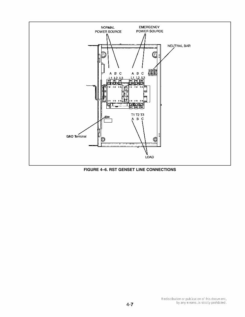
Figures 4–5 shows the Onan RST TransferSwitch to genset control connections, and Figure4–6 shows the power connections at the RSTTransfer Switch. Use the National Electrical Code(NFPA No. 70) as a guide for all AC wiringconnections.
4-4
▲WARNING!
▲WARNING!
FIGURE 4–3. TRANSFER SWITCH WITH 60 AMP LOAD
GENSET

4-5
NORMAL STANDBY
200 AMP RSTTRANSFER PANEL
200 AMPMAIN DISTRIBUTION
PANEL
TO ALL LOADS
200AMP
200 AMP OVER CURRENTPROTECTION DEVICE
METER
UTILITY SOURCE
FIGURE 4–4. TRANSFER SWITCH WITH 200 AMP LOAD
GENSET

4-6
FIGURE 4–5. RST TRANSFER SWITCH CONTROL CONNECTIONS
TB2-1
TB2
RST Transfer Switch
TB1
GRCA Genset
TB1-1
4-7
FIGURE 4–6. RST GENSET LINE CONNECTIONS

BATTERY
The genset has a 12 VDC, negative-ground con-trol and engine cranking system. The engine isequipped with an automatic, 6-amp nominal bat-tery charging circuit. A remote battery chargermust be connected to the genset to keep the bat-tery charged. The battery must be installed in thebattery tray and secured to the tray with the strap.See Figure 4–7. The genset requires a 12 voltBCI Group 26 battery [8.2L x 6.8W x 8.1H inches(208 x 173 x 205 mm) to the top of the terminals].
Battery Capacity
See Specifications for minimum battery require-ments.
Arcing can ignite the explosivehydrogen gas given off by the battery, caus-ing severe personal injury. The battery com-partment must be ventilated and must isolatethe battery from spark–producing equipment.
Battery Cables
To prevent injury due to accidental start-up, donot connect the battery cables to the battery untilthe installation has been completed and it is timeto start the set. See Installation Review andStartup.
Electric sparks can ignite gaseousfuel and cause severe personal injury ordeath.
Optional battery heater
Use the optional thermostatically controlledheater for the battery for more reliable starting inambient temperatures down to 0° F (-17.8° C).The heater fits in the battery tray and must beconnected to external AC power. The installer isresponsible for complying with all local electricalcodes. See Figure 4–1 and Table 4–1 for wiringdetails.
4-8
▲WARNING!
▲WARNING!
FIGURE 4–7. BATTERY INSTALLATION

INSTALLATION REVIEW
Before starting the genset inspect the installationand check off (✓) each of the following questionsif it can be answered “YES”. If a question cannotbe checked off, review the appropriate section inthe manual.
[ ] Is there access to the control switch for start-ing and stopping the genset?
[ ] Is there access to the circuit breaker andcontrol fuses for resetting or replacement?
[ ] Is there access to the engine oil drain fordraining engine oil?
[ ] Are the cooling air inlet and outlet openingsfree of obstructions?
[ ] Have the AC output connections been madeproperly?
[ ] Has an approved transfer switch beeninstalled to prevent connecting the genset tothe utility?
[ ] Has a properly sized battery been installed?[ ] Are all fuel connections tight?[ ] Is fuel supply pressure correct?[ ] Are electrical and fuel lines properly separat-
ed?[ ] Does engine exhaust disperse away from
buildings?
STARTUP
When all installation requirements have beenmet, connect the battery cables to the battery,positive (+) cable first.
Batteries give off explosive gasesthat can cause severe personal injury. Do notsmoke near batteries. Keep flames, sparks,pilot lights, electrical arcs and arc-producingequipment, switches, and all other ignitionsources well away.
Do not disconnect the battery cables while thegenset is cranking or running: the arcing canignite the explosive battery gases.
Read through the Operator’s Manual and performthe maintenance and pre-start checks instructed.The genset is shipped from the factory with theproper level of engine oil, but should be checkedbefore the genset is started. Start and operate thegenset, following all the instructions and precau-tions in the Operator’s Manual.
EXHAUST GAS IS DEADLY! Do notoperate the genset indoors.
Check for fuel and exhaust leaks and unusualnoises while the genset is running under full andintermediate loads. To calculate electrical loadssee Operation in the Operator’s Manual. Do notplace the genset in service until all leaks havebeen fixed and operation is satisfactory.
Before leaving the site, if the genset is readyto be placed in service, set the control switchto the AUTO position to provide automaticstandby power.
5-1
5. Installation Review and Startup
▲WARNING!
▲WARNING!

6-1
6. Specifications
GENERATOR:MODEL: Natural Gas LP VaporRated Power 9kW 11kWFrequency 60 HertzVoltage 120/240 voltsCircuit Breaker Rating 2-Pole, 50 amperesSpeed 3600 RPMFUEL CONSUMPTION:No-load 84,000 BTU/hr 37.0 ft 3/hrHalf-load 124,000 BTU/hr 54.0 ft 3/hrFull-load 190,000 BTU/hr 80.0 ft 3/hrNatural Gas Supply Pressure 7-11” WC (water column)
(178-381 mm) WCLP Supply Pressure (vapor) 9-13” WC (water column)
(178-381 mm) WCGas Supply Connection 3/4 inch NPT 3/4 inch NPTENGINE: Honda GX670 Twin V Overhead Cam (See Owners Manual for Specifications)CRANKING SYSTEM:Nominal Battery Voltage (BCI, GP 26) 12 VoltsBattery Cranking Capacity 530 CCA @ 00 F (-170 C)Nominal Battery Charging Output 6 amperes
ENCLOSURE:Contol Features
Enclosure Features
Exhaust SilencerInstallation Features
Unit Dimensions
WeightSound Level at Full Load* See Periodic Maintenance for oil filling instrustions.
Lighted Run/OFF Auto Switch Running Time Meter, 50 Amp UL Listed CircuitBreaker, DC Control Fuse, Large User Connection AreaSound Attenuated Drip-Proof Design, less than 70 dBA at 23 ft. (7M). EasyService Access, Internal Starting Battery Tray and Tie Down, Heavy DutyExterior High performance Fluoropolymer Finish Coat SystemOversized Silencer, Ultra-Low NoisePre-Mounted UV Resistant Plastic Installation Base, Convenient Electrical andGas Supply Connections, Ground Anchor System for Base Included45 inch (1143 mm) Length, 34 inch (864 mm) Width, 39 inch (986 mm) Height(including installation base)
575 Pounds (261 kg)Less than 70 dBA at 23 ft. (7 m)

7
7. Drawings

7-1

7-2

7-3

7-4

7-5

7-6

