catchments manual - canadian beacons project
TRANSCRIPT

Creating Catchments for the Boreal Forest of Canada: A Semi‐
automated Procedure using ArcGIS and Arc Hydro Tools
P. Vernier and K. Lisgo
April 13, 2011
Prepared by
The Canadian BEACONs Project

Table of Contents 1. Introduction .............................................................................................................................................. 3
1.1 ‐ Data Sources ..................................................................................................................................... 3
1.2 ‐ GIS‐based Tools ................................................................................................................................. 4
1.3 ‐ Scope and Limitations ....................................................................................................................... 5
2. Acquiring and Projecting Datasets ............................................................................................................ 5
2.1 ‐ Download Data ................................................................................................................................. 5
2.2 ‐ Project Data and Resample DEM ...................................................................................................... 6
3. Step‐by‐Step Procedure ............................................................................................................................ 6
3.1 – Set Target Locations ......................................................................................................................... 8
3.2 – Prepare Datasets .............................................................................................................................. 8
3.3 – Terrain Preprocessing ...................................................................................................................... 9
3.4 – Adjust flow direction in lakes ......................................................................................................... 12
3.5 – Create catchments for Canada ....................................................................................................... 12
3.6 – Extract Boreal catchments ............................................................................................................. 13
3.7 – Add catchment attributes .............................................................................................................. 14
3.8 – Calculate land and water area ....................................................................................................... 15
3.9 – Calculate Intactness ....................................................................................................................... 16
Optional – Extract ocean drainage catchments ...................................................................................... 17
4. Notes and Issues ..................................................................................................................................... 18
4.1 Identifying sinks ................................................................................................................................ 18
4.2 Correcting Problem catchments ....................................................................................................... 18
4.3 Eliminate small catchments tools ..................................................................................................... 20
Eliminate Small Catchments (version 1) ............................................................................................. 20
Eliminate Small Catchments (version 2) ............................................................................................. 21
5. References .............................................................................................................................................. 22
6. Appendix 1 – Troubleshooting ................................................................................................................ 22
6.1 DEM not recognized or does not exist .............................................................................................. 22

1. Introduction
Catchments are the primary spatial units on which the Benchmark Builder operates. Previously, the
Builder used a national catchments map1 that was available from the Geogratis web site. However,
these catchments were not ecologically‐defined drainage areas, and the map had several problems,
including the presence of numerous tiny sliver polygons that caused problems when running the
Benchmark Builder. Consequently, we explored the use of three alternative approaches to create a new
set of catchments for the Boreal region. The first and simplest approach uses a digital elevation model
(DEM) to generate both the stream network and the catchments. The second approach uses an existing
Canada‐wide drainage network along with a DEM to generate catchments. The third approach uses the
same datasets as the second approach but also requires that pour points first be identified2. After
testing the different approaches and to maintain compatibility with the current version of the
Benchmark Builder, we decided to use the second method. More recently, we refined the approach to
deal with clusters of anomalous catchments that were created in certain areas with flat topography and
many lakes. This required the use of an additional dataset describing the distribution of lakes in Canada.
In this report, we describe the data sources, GIS tools, and step‐by‐step procedures that we used to
creating catchments for the Boreal region of Canada.
1.1 Data Sources
Several datasets are required to create a national‐scale catchments coverage using the approach that
we describe, and all of them are freely available over the Internet.
Hydrology data. Currently, the most important data are the Atlas of Canada National Scale Frameworks
Hydrology datasets3 (1:1,000,000 scale), whose attributes are necessary for running the Benchmark
Builder. The hydrology datasets, which are based on 1:250,000 topographic maps, consist of several
themes, three of which are required:
1. The Drainage Network Skeleton data are comprised of linear features: single line rivers and flow
lines within waterbodies and coastlines.
2. The Waterbodies data are comprised of area features: lakes, intermittent waterbodies, islands,
and rivers wide enough to be represented as an area feature.
3. The Drainage Areas data are largely based on the Water Survey of Canada (WSC) drainage areas
boundaries at the sub‐sub‐basin level.
1 Catchments were created by constructing a polygon around each arc (line segment). Technically, the catchment polygons were constructed by creating a Voronoi diagram of the drainage network, producing a set of arcs whose vertices are equidistant from the nearest two drainage network arcs. Because there are often multiple line segments between nodes (junctions between stream orders), this causes the creation of many sliver polygons. 2 Pour points are the locations above which catchments will be determined i.e., for each catchment, they are the lowest elevation point where all water will drain to. 3 http://geogratis.cgdi.gc.ca/geogratis/en/option/select.do?id=27749

An alternative data set for future consideration is the National Hydro Network4 (NHN) which is based on
1:50,000 topographic maps. This data set is more detailed and also contains flow direction, but
modifications to the Builder code would be required.
Digital elevation model. A digital elevation model (DEM) is also required to build catchments, and at
least four different Canada‐wide DEM coverages are available: GTOPO30 data, Canadian Digital
Elevation Data (CDED), Shuttle Radar Topography Mission (SRTM), and Canada3D. GTOPO30 is a global‐
scale DEM with a resolution of approximately 1 km2 and was considered to be too coarse for our
purposes. CDED data is available at 1:50,000 and 1:250,000 scales, although there are several missing
areas (tiles) in the former dataset that limit its usefulness. The SRTM dataset has a 90‐m resolution but
is not available above the 60th parallel, which coincides with the northern boundary of several provinces
(e.g., BC and Alberta). We chose to use the Canada3D DEM5 because it was derived from the CDED
1:250,000 DEM and was available as a seamless coverage of Canada.
Intact Forest Landscapes map. The Global Forest Watch Canada (GFWC) Intact Forest Landscapes (IFL)
map (1:1,000,000 scale) depicts Canada's remaining forest landscape fragments within all eleven forest
ecozones using specified size thresholds of 5,000 ha for Boreal regions and 1,000 ha for temperate
forest regions (Lee et al. 2010).
Fire regions map. The fire regions map stratifies Canada’s forests into 5 or 10 fire regions based on
similarities in fire regime parameters such as frequency, size, and seasonality over a spatial grid of
10,000 km2 hexagons. The dataset was created by BEACONs and is used to inform benchmark size.
Boundary maps. We also used four boundary maps to define the area over which catchments were
generated or extracted: (i) a Canada boundary map that matches the extent of the DEM and drainage
network maps, (ii) a Boreal region map for extracting catchments that comprise the Boreal region, and
(iii) an ocean drainages map for extracting boreal catchments based on ocean drainage affiliation.
1.2 GISbased Tools
The catchment creation procedure was developed using ArcGIS 10 (with an ArcInfo license), the Spatial
Analyst extension, and two additional toolboxes that need to be downloaded and installed:
1. Arc Hydro Tools – An extensive set of tools for facilitating hydrologic and other water resource
analyses. The Terrain Preprocessing functions are used in two of the steps described in the step‐
by‐step procedures section.
HTTP download: http://resources.arcgis.com/content/hydro‐data‐model
FTP download: ftp://RiverHydraulics:river%[email protected] (go to the ArcHydro
directory and select the version of ArcGIS you are using)
4 http://www.geobase.ca/geobase/en/data/nhn/index.html 5 http://ftp2.cits.rncan.gc.ca/pub/canada3D/

2. Catchments Tools – A set of Python/ArcGIS tools created by BEACONs for automating the data
management and analysis steps described in the Step‐by‐Step Procedures section.
User’s Guide: http://www.beaconsproject.ca/catch
The Catchment Tools are available on request ([email protected])
1.3 Scope and Limitations
The catchments we generated, using the procedures described below, were developed specifically for
large‐scale (Boreal or Canada‐wide scale) conservation planning and analysis. Moreover, the coverage is
considered a work‐in‐progress that has already been revised a few times. It is not meant to be used for
identifying precise boundaries of watersheds or protected areas. In addition:
The catchments are generated using a semi‐automated procedure applied to all of Canada. No
specific considerations are given to adapting the procedures to reflect regional variation in
topography e.g., mountainous regions vs. flat and wet regions.
The catchments are not meant to replace “official” watershed boundaries such as those
developed by the Watershed Atlas of BC using 1:20,000 TRIM and topographic maps.
2. Acquiring and Projecting Datasets
Prior to following the catchment creation procedure (§ 3 Step‐by‐Step Procedure), it is necessary to
download and project all of the required datasets.
2.1 Download Data
The first step is to acquire and extract the required data. Although the tool is flexible enough to be used
with other datasets6 and study areas, for our purposes we used the following data:
Canada3D DEM – http://ftp2.cits.rncan.gc.ca/pub/canada3D/
Canada Drainage Network, Atlas of Canada 1,000,000 National Frameworks Data (includes
streams, lakes, and sub‐sub watersheds) –
ftp://ftp.geogratis.gc.ca/frameworkdata/hydrology/analytical/drainage_network/canada/
Intact Forest Landscapes, Global Forest Watch Canada (Lee et al. 2010) –
http://www.globalforestwatch.ca/datawarehouse/datawarehouse.htm
Fire Regions –BEACONs’ dataset, not yet publically available
Canada boundary7, Atlas of Canada 1,000,000 National Frameworks Data –
http://geogratis.cgdi.gc.ca/geogratis/en/download/framework.html
Boreal boundary – request from BEACONs ([email protected]) or download from
databasin.org
6 For example, a different measure of intactness could be used. 7 We removed the Great Lakes from the Canada boundary using the Drainage Network lake coverage.

Water Survey of Canada, Sub Sub Drainage Areas ‐
Ocean drainage boundaries, Atlas of Canada 1,000,000 National Frameworks Data –
ftp://ftp.geogratis.gc.ca/frameworkdata/drainage_areas/atlas_rollup/
For more information on the hydrology datasets: NRCAN. 2009. Atlas of Canada 1,000,000 National
Frameworks Data, Hydrology Version 6.0 ‐ A practical guide to the datasets
2.2 Project Data and Resample DEM
The second step is to project the data to a common system, in our case the Albers Equal Area projection
modified for the Boreal region. We also resampled the Canada3D DEM to a 250m resolution for analysis
at ocean drainage, Boreal, and national scales.
Project drainage network, lakes, and boundary feature classes to the Beacons Albers Equal Area
projection.
Project and resample Canada3D DEM to a 250m resolution.
The Albers Equal Area projection used by BEACONs has the following parameters:
Projection: Albers
False_Easting: 0.000000
False_Northing: 0.000000
Central_Meridian: ‐91.867000
Standard_Parallel_1: 49.000000
Standard_Parallel_2: 77.000000
Latitude_Of_Origin: 63.400000
Linear Unit: Meter (1.000000)
Geographic Coordinate System: GCS_North_American_1983
Angular Unit: Degree (0.017453292519943299)
Prime Meridian: Greenwich (0.000000000000000000)
Datum: D_North_American_1983
Spheroid: GRS_1980
Semimajor Axis: 6378137.000000000000000000
Semiminor Axis: 6356752.314140356100000000
Inverse Flattening: 298.257222101000020000
3. Step‐by‐Step Procedure
Several GIS processing steps are required to generate catchments for use by the Benchmark Builder
(Figure 1). In addition, prior to proceeding with the terrain preprocessing steps, it is necessary to set
target locations for raster and vector data and to copy several files into the Raster Data working
directory. In this section, we describe each step along with the required tools.
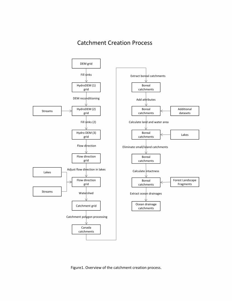
Figure1. Overview of the catchment creation process.
DEM grid
StreamsHydroDEM (2)
grid
HydroDEM (1) grid
Hydro DEM (3) grid
Flow direction grid
DEM reconditioning
Fill sinks
Fill sinks (2)
Flow direction grid
Catchment grid
Flow direction
Lakes
Streams
Adjust flow direction in lakes
Canada catchments
Watershed
Catchment polygon processing
Boreal catchments
Boreal catchments
Boreal catchments
Add attributes
Calculate land and water area
Extract boreal catchments
Boreal catchments
Ocean drainage catchments
Boreal catchments
Calculate intactness
Extract ocean drainages
Eliminate small/island catchments
Additional datasets
Lakes
Forest Landscape Fragments
Catchment Creation Process

3.1 – Set Target Locations
Description: The first step involves setting target locations for raster and vector data and ensuring that
those directories exist or are created. This step is very important and must be done prior to using the
Arc Hydro tools. As an example, we used the following locations to create the Boreal catchments:
Map Name: Layers
Raster Data: D:\gis_data\beacons\catchments\
Vector Data: D:\gis_data\beacons\catchments\catchments.gdb
Note: The Map Name (e.g., Layers ‐> D:\gis_data\beacons\catchments\Layers) refers to a workspace
(directory) where all of the data processing takes place. It is important, therefore, to make sure that
new files (e.g., the catchments shapefile) are created in this directory. After all the steps are
completed, the catchments shapefile and any other files can then be safely moved to a permanent
directory.
ArcGIS Procedure:
Right click on the menu bar in ArcMap and select Arc Hydro Tools 9.
Go to the ApUtilities menu and select the Target Locations menu item.
Select HydroConfig and specify the locations where data will be created.
3.2 – Prepare Datasets
Description: Several raster and vector datasets need to be copied to the workspace and manipulated
prior to creating the catchments. The data and procedures include:
Copy and rasterize the Canada boundary shapefile.
Copy the Boreal region boundary shapefile.
Copy the Canada3D raster DEM and overlay it with the Canada raster.
Copy and clip the Atlas of Canada skeleton shapefile with the Canada boundary shapefile;
rasterize the resulting stream network shapefile.
Copy and clip the Atlas of Canada lakes shapefile with the Canada boundary shapefile.
Copy and dissolve (internal boundaries) of the GFWC study area boundary shapefile.

Copy the GFWC intact forest landscapes shapefile.
Catchment Tools – Prepare Datasets: The Prepare Datasets tool copies and manipulates all of the data
that will be required to create catchments for the Boreal region. The user only needs to identify the
location of the workspace, the datasets, and the analysis cellsize.
Run the Prepare Catchments tool located in the Catchments toolset of the Beacons Toolbox.
Verify that all of the parameters are filled properly and click OK.
3.3 – Terrain Preprocessing
Description: The objective of the terrain preprocessing step is to modify the DEM by removing small
errors, imposing existing stream networks, and adjusting flow direction in lakes. Together these steps
ensure the creation of a hydrologically correct DEM that is compatible with existing streams and lakes
coverages. The procedure consists of four broad steps:
1. Fill Sinks. DEMs often have small errors that are known as sinks – areas that are surrounded by
higher elevation values. These areas of internal drainage can cause problems when calculating a
flow direction map and it is often recommended that they be removed. Thus, in the first step,
we fill the sinks in the DEM to remove small imperfections in the data.
2. DEM Reconditioning. DEMs can be modified by imposing linear features onto them i.e., stream
burning. Essentially, streams are pushed into the DEM by a certain depth ensuring better
hydrological flow and connectivity, and more consistency between the two datasets. In the
second step, we use the DEM Reconditioning function to modify the filled DEM by imposing
linear features onto them – in this case the Atlas of Canada drainage network.
3. Fill Sinks (2). New sinks may have been created through the DEM reconditioning process. As a
result, it is necessary to fill new sinks in the reconditioned DEM.

4. Flow Direction. A flow direction map is one of two required inputs for creating catchments. In
the fourth step, we used the filled reconditioned DEM to generate a flow direction map – a map
that identifies the flow direction from each cell to its steepest downslope neighbour.
Catchment Tools – Terrain Preprocessing: The Terrain Preprocessing tool provides a convenient tool for
running the four terrain preprocessing steps.
Select the Terrain Preprocessing tool and fill in the location of the DEM, streams (drainage
network), and lakes. Note that these are all located in the previously defined workspace (see §
3.1). Make sure not to use the original datasets.
Note: Alternatively, the four preceding steps can also be completed one at a time using the Arc Hydro Tools. This may be desirable if one wants to see the results of the intermediate steps, for example, to see what the DEM looks like after stream burning. Instructions for Arc Hydro:
Fill Sinks. Run the Fill tool located under the Preprocessing menu of the Arc Hydro Tools. Select the raw DEM as the Input surface raster. Optionally, specify the Z limit i.e., the maximum depth that depressions should be to be considered sinks.

DEM Reconditioning. Run the DEM Reconditioning tool located under the Preprocessing menu of the Arc Hydro Tools. Select the “filled” DEM and Atlas of Canada drainage network. For the Boreal catchments, we accepted the default values for the other four parameters.
Fill Sinks (2). Run the Fill function once again using the reconditioned DEM as the input surface raster.
Flow Direction. Run the Flow Direction tool, selecting as input the filled and reconditioned DEM.
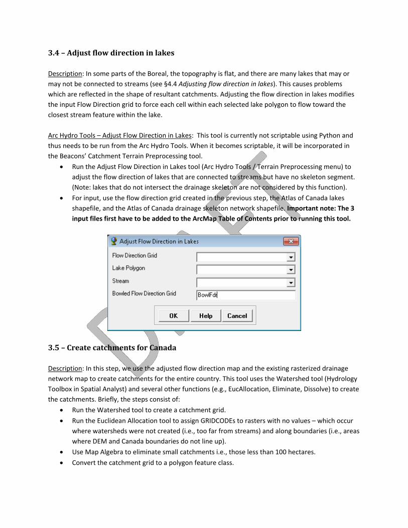
3.4 – Adjust flow direction in lakes
Description: In some parts of the Boreal, the topography is flat, and there are many lakes that may or
may not be connected to streams (see §4.4 Adjusting flow direction in lakes). This causes problems
which are reflected in the shape of resultant catchments. Adjusting the flow direction in lakes modifies
the input Flow Direction grid to force each cell within each selected lake polygon to flow toward the
closest stream feature within the lake.
Arc Hydro Tools – Adjust Flow Direction in Lakes: This tool is currently not scriptable using Python and
thus needs to be run from the Arc Hydro Tools. When it becomes scriptable, it will be incorporated in
the Beacons’ Catchment Terrain Preprocessing tool.
Run the Adjust Flow Direction in Lakes tool (Arc Hydro Tools / Terrain Preprocessing menu) to
adjust the flow direction of lakes that are connected to streams but have no skeleton segment.
(Note: lakes that do not intersect the drainage skeleton are not considered by this function).
For input, use the flow direction grid created in the previous step, the Atlas of Canada lakes
shapefile, and the Atlas of Canada drainage skeleton network shapefile. Important note: The 3
input files first have to be added to the ArcMap Table of Contents prior to running this tool.
3.5 – Create catchments for Canada
Description: In this step, we use the adjusted flow direction map and the existing rasterized drainage
network map to create catchments for the entire country. This tool uses the Watershed tool (Hydrology
Toolbox in Spatial Analyst) and several other functions (e.g., EucAllocation, Eliminate, Dissolve) to create
the catchments. Briefly, the steps consist of:
Run the Watershed tool to create a catchment grid.
Run the Euclidean Allocation tool to assign GRIDCODEs to rasters with no values – which occur
where watersheds were not created (i.e., too far from streams) and along boundaries (i.e., areas
where DEM and Canada boundaries do not line up).
Use Map Algebra to eliminate small catchments i.e., those less than 100 hectares.
Convert the catchment grid to a polygon feature class.
Clip catchment polygon to boundary of Canada (this removes bits of raster that extend beyond
border of Canada).
Run the Eliminate tool to remove any remaining small polygons.
Use the Dissolve tool to remove any remaining duplicate GRIDCODEs.
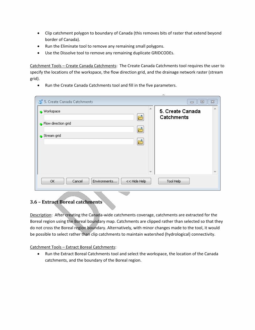
Catchment Tools – Create Canada Catchments: The Create Canada Catchments tool requires the user to
specify the locations of the workspace, the flow direction grid, and the drainage network raster (stream
grid).
Run the Create Canada Catchments tool and fill in the five parameters.
3.6 – Extract Boreal catchments
Description: After creating the Canada‐wide catchments coverage, catchments are extracted for the
Boreal region using the Boreal boundary map. Catchments are clipped rather than selected so that they
do not cross the Boreal region boundary. Alternatively, with minor changes made to the tool, it would
be possible to select rather than clip catchments to maintain watershed (hydrological) connectivity.
Catchment Tools – Extract Boreal Catchments:
Run the Extract Boreal Catchments tool and select the workspace, the location of the Canada
catchments, and the boundary of the Boreal region.

3.7 – Add catchment attributes
Description: In this step, several important attributes are calculated (e.g., area and perimeter) or added
from existing maps (e.g., stream network, drainage area, and fire region characteristics) for later use
with the Benchmark Builder:
Area
Perimeter
SKELUID – unique identifier of the stream arc for which the catchment was created; it
corresponds to the UID_v6 attribute of the Atlas of Canada 1,000,000 Drainage Network,
Version 6. The SKELUID is also the same as the GRIDCODE in the catchment dataset.
CATCHNUM – unique identifier for each catchment
ODRAINAGE – Ocean Drainage Areas
WSCSSDA – Water Survey of Canada Subsub Drainage Areas; the subsub drainage areas (SSDA)
are nested within the ocean drainage areas. The SSDA dataset includes an ODRAINAGE
attribute. This dataset was also used to assign the ODRAINAGE to the catchments.
EMFS – estimated maximum fire size from the BEACONs’ fire regionalization dataset
This tool uses the ArcGIS Join tools (spatial and attribute) to add new attributes to the catchment
shapefile. The ODRAINAGE, WSCSSDA, and EMFS are assigned to a catchment based on the location of
the catchment’s centroid.
NOTE: The tool assigns ODRAINAGE and WSCSSDA as described above. However, some catchments are
incorrectly assigned because, in a handful of cases, the location of the catchment’s centroid does not
accurately represent the location of the catchment’s stream arc. We manually corrected these errors so

that ODRAINAGE and WSCSSDA are assigned based on the location of the catchment’s stream arc.
Stream arcs are nested within the ocean drainage areas and subsub drainage areas.
Catchment Tools – Add Catchment Attributes:
Run the Add Catchment Attributes tool in the Catchment Tools and specify the locations of the
workspace, catchment shapefile, WSC sub‐sub drainage areas shapefile, and the fire region
shapefile.
3.8 – Calculate land and water area
Description: One of the criteria used by Builder to inform the construction of benchmarks is minimum
terrestrial area (i.e., the minimum terrestrial area a contiguous set of catchments needs to have to
qualify as a benchmark area). Currently, minimum size is derived from the local estimated maximum fire
size from the fire regions map. Since most catchments include lakes, the area of lakes needs to be
subtracted from the total area of a catchment to derive the catchment’s terrestrial area. In this step, the
total area of each catchment is divided into terrestrial and aquatic area to facilitate calculation of the
minimum size criteria.
NOTE: The Atlas of Canada 1,000,000 Drainage Network lakes polygon (version 6) coverage includes
lakes, double‐line rivers, and wetlands.
Catchment Tools – Calculate Land & Water Area:
Run the Calculate Catchment Land & Water Area tool in the Catchment Tools and specify the
location of the workspace, catchment shapefile, Drainage Network Atlas of Canada lakes
shapefile, and the Boreal region boundary map. Three new attributes are created: Area_water,
Area_land, and Area_total.

3.9 – Calculate Intactness
Description: The Global Forest Watch Canada (GFWC) Intact Forest Landscapes (IFL) map is used to
calculate intactness for each catchment based on the proportion of the catchment area that is 100%
intact. The tool makes use of the Arc/Info Identity tool and currently only works for catchments in the
forest ecozones of Canada. GFWC’s Intact Forest Landscapes coverage does not extend beyond the
forest ecozones.
GFWC’s IFL dataset was created using Statistic’s Canada boundary shapefile of Canada. The catchments
were created using the Atlas of Canada Canada boundary. To account for discrepancies between these
two boundaries, catchments are clipped to the Statistics Canada boundary before calculating the
proportion of area intact for each catchment (IFL_2010). The IFL_2010 attribute is transferred from the
clipped catchment shapefile to the original shapefile using a join based on GRIDCODE.
CatchmentTools – Calculate Boreal Intactness:
Run the Calculate Boreal Intactness tool in Catchment Tools and specify the location of the
output workspace, the Boreal catchments map, and the GFWC intact forest landscape map.

Optional – Extract ocean drainage catchments
In some cases, it may desirable to extract a subregion of the Boreal catchments map based on ocean
drainage boundaries. This tool extracts catchments whose boundaries are defined by the Boreal region
and one of the four ocean drainages intersecting the Boreal region. Each catchment is assigned to an
ocean drainage based on the location of its associated stream segment. No streams cross drainage
boundaries. In all cases, catchments are selected rather than clipped to maintain watershed (hydrologic)
connectivity because catchment boundaries do not necessarily line up with ocean boundaries.
Catchment Tools – Extract OD Catchments:
Run the Extract OD Catchments tool in Catchment Tools. Select the location of the workspace
and the Boreal catchments.

4. Notes and Issues
4.1 Identifying sinks
DEMs often have small errors that are known as sinks – areas that are surrounded by higher elevation
values. These areas of internal drainage can cause problems when calculating a flow direction map and
it is often recommended that they be removed. However, in areas of low relief, sinks may represent true
features such as glacial and karst areas or bogs and lakes – all of which are common in the Boreal region
(Figure 2).
a) Lakes
b) Sinks
Figure 2. Comparison of actual lakes (a) and DEM sinks (b).
4.2 Correcting Problem catchments
In certain areas of the Boreal region, a combination of flat topography and numerous lakes (including
many that are not connected to streams) result in the creation of clusters of narrow parallel catchments
(Figure 3). To fix this problem, we used a combination of DEM reconditioning (see also § 3.3) and
adjusting flow direction in lakes (see also § 3.4). Brief descriptions of both functions are provided here:
DEM reconditioning (stream burning). From the Arc Hydro Tools help file: “The DEM Reconditioning
function (DEM Manipulation menu) modifies Digital Elevation Models (DEMs) by imposing linear
features onto them (burning/fencing). This function is an implementation of the AGREE method
developed by Ferdi Hellweger at the University of Texas at Austin in 1997.”8
8 http://www.ce.utexas.edu/prof/maidment/GISHYDRO/ferdi/research/agree/agree.html
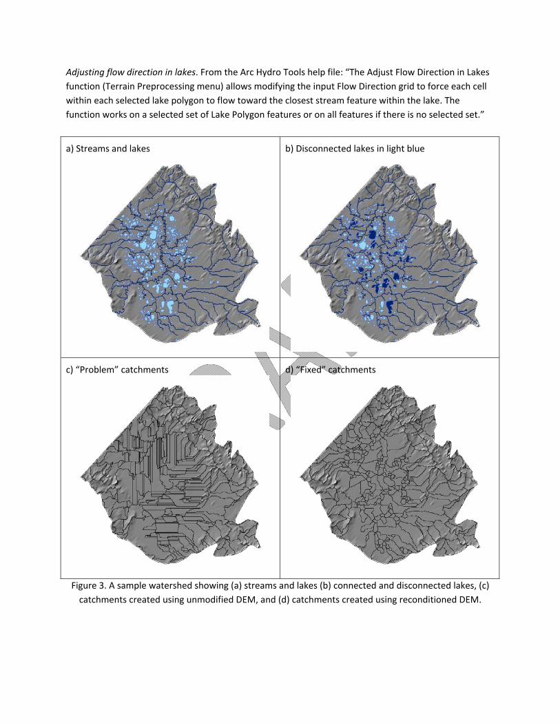
Adjusting flow direction in lakes. From the Arc Hydro Tools help file: “The Adjust Flow Direction in Lakes
function (Terrain Preprocessing menu) allows modifying the input Flow Direction grid to force each cell
within each selected lake polygon to flow toward the closest stream feature within the lake. The
function works on a selected set of Lake Polygon features or on all features if there is no selected set.”
a) Streams and lakes b) Disconnected lakes in light blue
c) “Problem” catchments d) “Fixed” catchments
Figure 3. A sample watershed showing (a) streams and lakes (b) connected and disconnected lakes, (c)
catchments created using unmodified DEM, and (d) catchments created using reconditioned DEM.

4.3 Eliminate small catchments tools
There are two versions of this tool and neither any longer used as a separate step (standalone script) in
the step‐by‐step catchments creation procedure. However, the tools may still be useful in other
situations and are thus described here. Both tools were designed to eliminate small catchments based
on a user defined mininum size, for example, if a minimum catchment size of 100 ha is desired for the
purpose of regional conservation planning. Both versions of the tool use the ArcInfo Eliminate function
one or more times. The second version also considers the stream flow direction so as to merge small
catchments with upstream catchments.
Eliminate Small Catchments (version 1)
Description: This is a utility script that can be used to eliminate small catchments e.g., those less than
100 ha. The number of iterations is set to 2 but can be changed to any value. A minimum of 2 iterations
is recommened in case new small catchments (slivers) are created during the first iteration.
Input: A catchment feature class.
Output: A new catchments feature class with all polygons under a user specified size threshold
eliminated.
Requirements: ArcInfo license.
Instructions: To use the tool, simply click on the Eliminate Small Catchments (version 1) tool to launch
the dialog box. Four parameters need to be entered to run the tool:
Workspace: Specify workspace where new catchments will be created.
Catchments feature class: Specify the location of the catchments feature class.
Minimum Size (ha): Specify the minimum size of polygons in hectares.
Number of iterations: Specify the number of iterations to run (default is 2).

Eliminate Small Catchments (version 2)
Description: This is a utility script that can be used to eliminate small catchments e.g., those less than
100ha. It is similar to version 1 but merges small catchments to neighbouring upstream catchments.
Land and water areas are recalculated for all catchments.
Input: A catchment feature class.
Output: A new catchments feature class with all polygons under a user specified size threshold
eliminated.
Requirements: GPEliminateCatchments.dll9
Instructions: To use the tool, simply click on the Eliminate Small Catchments (version 2) tool to launch
the dialog box. Ten parameters need to be entered to run the tool:
Input features: Specify the name and location of the input catchments feature class.
Output features: Specify the name and location of the output catchments feature class.
Attributes: Seven attributes need to be specified; the defaults should be sufficient.
Eliminate Size: Specify the minimum size of polygons (default = 1000000 m2).
9 To use the DLL, put it in your “C:\Program Files\ArcGIS\Bin” directory. Then run this command to register it: “C:\Windows\Microsoft.NET\Framework\v2.0.50727\regasm.exe C:\Program Files\ArcGIS\Bin\GPEliminateCatchments.dll". Note that if you are installing a newer version of the DLL you will first need to unregister the old DLL using this command: “c:\Windows\Microsoft.NET\Framework\v2.0.50727\regasm.exe /u C:\Program Files\ArcGIS\Bin\GPEliminateCatchments.dll"

5. References
Djokic, D. 2008. Comprehensive Terrain Preprocessing Using Arc Hydro Tools. ESRI.
Lee, P.G., M. Hanneman, J.D. Gysbers, R. Cheng, and W. Smith. 2010. Atlas of Canada’s Intact Forest Landscapes. Edmonton, Alberta: Global Forest Watch Canada 10th Anniversary Publication #1. 74 pp.
6. Appendix 1 – Troubleshooting
6.1 DEM not recognized or does not exist
Problem: This problem was documented when using the Terrain Preprocessing tool (step 3.3). An error
was generated stating that the selected DEM is not recognized or does not exist. Presumably, this
problem could also occur when using other tools that use input grids.
Solution: Go to the Customize menu and make sure the Spatial Analyst extension is selected.