catalogue main index
TRANSCRIPT

PROPORTIONAL CARTRIDGE VALVES
W 36 / 2015 Index
Via Malavolti, 36 • 41122 Modena • ITALY • Phone +39 (059) 254895 • Fax +39 (059) 253512 mail: [email protected] • www.tecnord.com
4484 Boeing Drive Rockford, IL 61109 • USA • Phone +1 (815) 397-6628 • Fax +1 (815) 397-2526 mail: [email protected] • www.delta-power.com
CATALOGUE MAIN INDEX
ACCESSORIES ENGINEERING DATA
MOTORIZED VALVES
COILS DATA
MECHANICAL PRESSURE COMPENSATORS
PROPORTIONALCONTROLS

PROPORTIONAL CARTRIDGE VALVES
Index W 36 / 2015
Via Malavolti, 36 • 41122 Modena • ITALY • Phone +39 (059) 254895 • Fax +39 (059) 253512 mail: [email protected] • www.tecnord.com
4484 Boeing Drive Rockford, IL 61109 • USA • Phone +1 (815) 397-6628 • Fax +1 (815) 397-2526 mail: [email protected] • www.delta-power.com
QUICK SELECTION GUIDE
PROPORTIONAL CONTROLS - Page PT1
MOTORIZED CARTRIDGES - Page DC1
DIRECT ACTING GPM PSI LPM BAR CAVITY MODEL PAGE
1 700 4 50 slip-in IP-DAR-43C-L PT4
1 5000 4 345 slip-in IP-DAR-43C-H PT4
PILOT OPERATED GPM PSI LPM BAR CAVITY MODEL PAGE
7.9 700 30 50 slip-in IP-PRZ-59 PT6
7.9 700 30 50 7/8-14 EG-TRZ-42-L PT8
7.9 3500 30 241 7/8-14 EG-TRZ-42-H PT10
NORMALLY CLOSED GPM PSI LPM BAR CAVITY MODEL PAGE
12 3000 45 207 7/8-14 EE-PRB PT14
NORMALLY OPEN GPM PSI LPM BAR CAVITY MODEL PAGE
12 3000 45 207 7/8-14 EE-PRD PT16
SPOOL TYPE GPM PSI LPM BAR CAVITY MODEL PAGE
13.2 3500 50 245 7/8-14 EE-P2G PT20
23.7 3500 90 245 1 1/16-12 ET-P2S PT22
POPPET TYPE GPM PSI LPM BAR CAVITY MODEL PAGE
6.5 3500 25 245 3/4-16 EB-P2A PT24
12 3500 45 245 7/8-14 EE-P2A PT26
29 3500 110 245 1 1/16-12 ET-P2A PT28
SPOOL TYPE GPM PSI LPM BAR CAVITY MODEL PAGE
8 3500 30 245 7/8-14 EE-P2H PT32
POPPET TYPE GPM PSI LPM BAR CAVITY MODEL PAGE
12 3500 45 245 7/8-14 EG-F2A PT36
12 3500 45 245 1/16-12 EU-F2A PT38
SPOOL TYPE GPM PSI LPM BAR CAVITY MODEL PAGE
1 2
3
1 2
3
6 3500 22 245 7/8-14 EF-F3G PT42
16 3500 60 245 1/16-12 EU-F3G PT44
MOTOR SPOOL TYPE GPM PSI LPM BAR CAVITY MODEL PAGE
(3) (1)
(2) (4)
3 3500 12 245 3/4-16 EQ-S4M PT48
6 3500 23 245 7/8-14 EG-S4M PT50
CYLINDER SPOOL TYPE GPM PSI LPM BAR CAVITY MODEL PAGE
(3) (1)
(2) (4)
3 3500 12 245 3/4-16 EQ-S4P PT52
6 3500 23 245 7/8-14 EG-S4P PT54
FLOW RESTRICTORS (NEEDLE VALVES) GPM PSI LPM BAR CAVITY MODEL PAGE
12 3500 45 245 7/8-14 AE-NVA DC4
40 3500 150 245 1 5/16-12 AJ-NVA DC6
2W PRES. COMPENSATED FLOW REGULATORS GPM PSI LPM BAR CAVITY MODEL PAGE
24 3500 90 245 1 5/16-12 AJ-FCA DC8
3W PRES. COMPENSATED FLOW REGULATORS GPM PSI LPM BAR CAVITY MODEL PAGE
24 3500 90 245 1 5/16-12 AK-FCQ DC10
RELIEF VALVES GPM PSI LPM BAR CAVITY MODEL PAGE
37 3500 140 245 1 5/16-12 AJ-RVR DC14
PRESSURE REDUCING VALVES GPM PSI LPM BAR CAVITY MODEL PAGE
10 3000 38 207 7/8-14 AF-PRP DC16
PROPORTIONAL PRESSURE REDUCING / RELIEVING VALVES
MOTORIZED FLOW REGULATORS MOTORIZED PRESSURE CONTROLS
2 WAY NORMALLY OPEN PROPORTIONAL FLOW CONTROL VALVES
2 WAY NORMALLY CLOSED PRESS. COMPENSATED PROP. FLOW REGULATOR VALVES
3 WAY NORMALLY CLOSED PRESS. COMPENSATED PROP. FLOW REGULATOR VALVES
4W/3P PROPORTIONAL DIRECTIONAL CONTROL VALVES
PROPORTIONAL PRESSURE RELIEF VALVES
PROPORTIONAL PRESSURE RELIEF VALVES

PROPORTIONAL CARTRIDGE VALVES
W 36 / 2015 Index
Via Malavolti, 36 • 41122 Modena • ITALY • Phone +39 (059) 254895 • Fax +39 (059) 253512 mail: [email protected] • www.tecnord.com
4484 Boeing Drive Rockford, IL 61109 • USA • Phone +1 (815) 397-6628 • Fax +1 (815) 397-2526 mail: [email protected] • www.delta-power.com
MECHANICAL PRESSURE COMPENSATORS - Page MC1
COILS DATA - Page CT1
ACCESSORIES - Page AC1
ENGINEERING DATA - Page ED1
QUICK SELECTION GUIDE
GPM PSI LPM BAR CAVITY MODEL PAGE
8 3500 30 245 7/8-14 DF-CP2 MC4
19 3500 70 245 Special QC-CP2 MC6
GPM PSI LPM BAR CAVITY MODEL PAGE
10 3500 38 245 7/8-14 DF-TCS MC10
GPM PSI LPM BAR CAVITY MODEL PAGE
10 3500 38 245 7/8-14 DF-PCR MC14
40 3500 151 245 1 1/16 –12 TR-PCA MC16
40 3500 151 245 1 5/16–12 SL-PCA MC18
33 3500 120 245 Special QC-CP3 MC20
GPM PSI LPM BAR CAVITY MODEL PAGE
10 3500 38 245 7/8-14 DG-TCB MC24
TYPE ID WIDTH HEIGHT PAGE
PJ 1/2 36 38.5 CT4
A 13.3 30 39 CT5
V 13.2 37.5 50 CT6
L 16.1 37.5 50 CT7
Z 19.1 46.5 56 CT8
F 19.1 37 50 CT9
DESCRIPTION PAGE
Valve Bodies AC2
Cavity Plugs AC6
Manual Override Options AC11
PILOT Piston Assemblies AC13
Standard Knob Assemblies AC14
DESCRIPTION PAGE
Cavity Data ED2
General Installation Note ED28
Valve Mnemonic Code ED30
2 WAY COMPENSATING/REDUCING VALVES
STANDARD COILS
2 WAY BYPASS TYPE FOR 3 WAY FLOW CONTROL
4 WAY PRIORITY TYPE COMPENSATOR WITH BYPASS LINE
2 WAY RESTRICTIVE TYPE COMPENSATORS

PROPORTIONAL CONTROLW
9 /
201
6
Page PT1
Via Malavolti, 36 • 41122 Modena • ITALY • Phone +39 (059) 254895 • Fax +39 (059) 253512 mail: [email protected] • www.tecnord.com
4484 Boeing Drive Rockford, IL 61109 • USA • Phone +1 (815) 397-6628 • Fax +1 (815) 397-2526 mail: [email protected] • www.delta-power.com
WARNING: the specifications/application data shown in our catalogs and data sheets are intended only as a general guide for the product described (herein). Any specific application should not be undertaken without independent study, evaluation, and testing for suitability.
PROPORTIONAL PRESSURE CONTROLS
PROPORTIONAL PRESSURE REDUCING / RELIEVING VALVES ...................................................................... PT3
PROPORTIONAL PRESSURE RELIEF VALVES .................................................................................................. PT13
PROPORTIONAL FLOW CONTROLS
2 WAY NORMALLY CLOSED PROPORTIONAL FLOW REGULATOR VALVES ................................................... PT19
2 WAY NORMALLY OPEN PROPORTIONAL FLOW REGULATOR VALVES ....................................................... PT31
2 WAY NOR. CLOSED PRESSURE COMPENSATED PROP. FLOW REGULATOR VALVES .............................. PT35
3 WAY NOR. CLOSED PRESSURE COMPENSATED PROP. FLOW REGULATOR VALVES .............................. PT41
4W/3P PROPORTIONAL DIRECTIONAL CONTROL VALVES ............................................................................. PT47
Section / Description page
PROPORTIONAL CONTROLS

PROPORTIONAL CONTROL
Page PT2
W 9 / 2016
Via Malavolti, 36 • 41122 Modena • ITALY • Phone +39 (059) 254895 • Fax +39 (059) 253512 mail: [email protected] • www.tecnord.com
4484 Boeing Drive Rockford, IL 61109 • USA • Phone +1 (815) 397-6628 • Fax +1 (815) 397-2526 mail: [email protected] • www.delta-power.com
WARNING: the specifications/application data shown in our catalogs and data sheets are intended only as a general guide for the product described (herein). Any specific application should not be undertaken without independent study, evaluation, and testing for suitability.

PROPORTIONAL CONTROLW
9 /
201
6
Page PT3
Via Malavolti, 36 • 41122 Modena • ITALY • Phone +39 (059) 254895 • Fax +39 (059) 253512 mail: [email protected] • www.tecnord.com
4484 Boeing Drive Rockford, IL 61109 • USA • Phone +1 (815) 397-6628 • Fax +1 (815) 397-2526 mail: [email protected] • www.delta-power.com
WARNING: the specifications/application data shown in our catalogs and data sheets are intended only as a general guide for the product described (herein). Any specific application should not be undertaken without independent study, evaluation, and testing for suitability.
DIRECT ACTING GPM PSI LPM BAR CAVITY MODEL PAGE
1 700 4 50 slip-in IP-DAR-43C-L PT4
1 5000 4 345 slip-in IP-DAR-43C-H PT4
PILOT OPERATED GPM PSI LPM BAR CAVITY MODEL PAGE
7.9 700 30 50 slip-in IP-PRZ-59-AM12 PT6
7.9 700 30 50 7/8-14 EG-TRZ-42-L PT8
7.9 3500 30 241 7/8-14 EG-TRZ-42-H PT10
Typical application for the IP-DAR-43 is the control of a metering spool on a directional valve.
PROPORTIONAL PRESSURE REDUCING / RELIEVING VALVES
TYPICAL SCHEMATIC

Via Malavolti, 36 • 41122 Modena • ITALY • Phone +39 (059) 254895 • Fax +39 (059) 253512 mail: [email protected] • www.tecnord.com
4484 Boeing Drive Rockford, IL 61109 • USA • Phone +1 (815) 397-6628 • Fax +1 (815) 397-2526 mail: [email protected] • www.delta-power.com
WARNING: the specifications/application data shown in our catalogs and data sheets are intended only as a general guide for the product described (herein). Any specific application should not be undertaken without independent study, evaluation, and testing for suitability.
Page PT4
PROPORTIONAL CONTROLW
9 / 2016
IP-DAR-43C DIRECT ACTING PROPORTIONAL, PRESSURE REDUCING/RELIEVING, SLIP-IN TYPE
DESCRIPTIONSpecial cavity, slip-in style flange retained, direct acting proportional, pressure reducing/relieving valve.
OPERATIONThe IP-DAR-43C-AJ12 generates a variable pressure in response to a PWM (Pulse Width Modulated) current signal. With no current applied to the proportional solenoid, the inlet port 2 (P) is blocked and the regulated port 3 (U) is vented to port 1 (T). As current is increased, fluid pressure is proportionally controlled at the regulated port 3 (U). On attainment of proportionally determined pressure at 3 (U), the cartridge shifts to block flow at 2 (P), thereby regulating pressure at 3 (U). In this mode, the valve also will relieve 3 (U) to 1 (T) at a variable value over the set reducing pressure.
FEATURES • Slip-in style.• Efficient wet-armature construction.• Integral waterproof coil.• Continuous duty rated solenoid.
Flanged retained product. The coil is an integral part of the valve and is not serviceable. Eventual tank pressure exceeding 0 bar, has to be added to reduced pressure value.
Nominal Flow 1 GPM (4 LPM) @ 8 bar Delta PMax Inlet Pressure “H” version 5000 PSI (345 bar)Max Inlet Pressure “L” version 700 PSI (50 bar)Controlled Pressure Range 0÷25 bar / 0÷30 bar (see graph)Reduced Pressure Tolerance ±5%Max Back-Pressure at T Port 20 barInternal Leakage 15 ml/min @ 500 PSI (35 bar) inlet 35 ml/min @ 5000 PSI (350 bar) inletViscosity Range 36 to 3000 SSU (3 to 647 cSt)Filtration ISO 18/15/13Media Operating Temp. Range -30°C / +100°CWeight .54 lbs (.25 kg)Operating Fluid Media General Purpose Hydraulic FluidCavity T043Cavity Tool Kit K-T043Flange Mounting Screws and Torque M4x10 / 3ft-lbs (4 Nm)
VALVE SPECIFICATIONS
Current Supply Characteristics PWM (Pulse Width Modulation)Rated Current Range 200÷1500 (12 V coil) 100÷750 (24 V coil)PWM or Super-Imposed Dither Freq. 100-200 HzCoil Resistance (12 VDC) 5.4 Ohm ±5% at 68°F (20°C)Coil Resistance (24 VDC) 22 Ohm ±5% at 68°F (20°C)Max Power Consumption 12 Watt (20°C)Protection Degree IP 67 according to IEC 529Coil Termination Deutsch-Integral DT04-2P AMP Jr. Timer 84-9419Color Connectors Black
COIL SPECIFICATIONS
HYDRAULIC SYMBOL
PERFORMANCE
1 (T)
2 (P)
3 (U)
Reduced pressure (bar) vs. Current (mA)12 V and 24 V Coil
1 (T)
2 (P)
3 (U)
P (bar)
l (mA) @ 12V l (mA) @ 24V

Via Malavolti, 36 • 41122 Modena • ITALY • Phone +39 (059) 254895 • Fax +39 (059) 253512 mail: [email protected] • www.tecnord.com
4484 Boeing Drive Rockford, IL 61109 • USA • Phone +1 (815) 397-6628 • Fax +1 (815) 397-2526 mail: [email protected] • www.delta-power.com
WARNING: the specifications/application data shown in our catalogs and data sheets are intended only as a general guide for the product described (herein). Any specific application should not be undertaken without independent study, evaluation, and testing for suitability.
Page PT5
PROPORTIONAL CONTROLW
9 /
201
6
IP-DAR-43C – – – –
COILTERMINATION
VOLTAGE INLETPRESSURE
MAXREGULATEDPRESSURE
OPTIONS BODIES
AJ - AMP Jr. Timer 12 VDC L - up to 700 PSI (50 bar)
25 bar A0 - NBR seals and 300 μm
(50 mesh) screen on port 2
Blank - Without body
DT - Deutsch DT04
24 VDC H - up to 5000 PSI (350 bar)
30 bar N - 1/4” BSP Ports
DH - Deutsch DT04 Horizontal
S - #6 SAE Ports
DIMENSIONS
ORDERING INFORMATION
DT version AJ version DH version

Via Malavolti, 36 • 41122 Modena • ITALY • Phone +39 (059) 254895 • Fax +39 (059) 253512 mail: [email protected] • www.tecnord.com
4484 Boeing Drive Rockford, IL 61109 • USA • Phone +1 (815) 397-6628 • Fax +1 (815) 397-2526 mail: [email protected] • www.delta-power.com
WARNING: the specifications/application data shown in our catalogs and data sheets are intended only as a general guide for the product described (herein). Any specific application should not be undertaken without independent study, evaluation, and testing for suitability.
Page PT6
PROPORTIONAL CONTROLW
9 / 2016
IP-PRZ-59-AM12 PILOT OPERATED PROPORTIONAL, PRESSURE REDUCING/RELIEVING, SLIP-IN TYPE
DESCRIPTIONSpecial cavity, flange retained, slip-in proportional pressure reducing/relieving valve.
OPERATIONThe IP-PRZ-59-AM12 generates a variable pressure in response to a PWM (Pulse Width Modulated) current signal. With no current applied to the proportional solenoid, the inlet port 3 (P) is blocked and the regulated port 2 (U) is vented to port 1 (T). As current is increased, fluid pressure is proportionally controlled at the regulated port 3 (P). On attainment of proportionally determined pressure at 2 (U), the cartridge shifts to block flow at 3 (P), thereby regulating pressure at 2 (U). In this mode, the valve also will relieve 2 (U) to 1 (T) at a variable value over the set reducing pressure.
FEATURES • Economical slip-in style.• Integral waterproof coil.• Efficient wet-armature construction.• Hardened parts for long life.
Nominal Flow 7.9 GPM (30 LPM) @ 3 bar DeltaPMax Inlet Pressure 700 PSI (50 bar)Controlled Pressure Range (see graph)Max Internal Leakage <500 cc/min @ 35 barViscosity Range 5 to 5000 cStFiltration ISO 18/15/13Media Operating Temp. Range -30°C / +100°CWeight .63 lbs (.29 kg)Operating Fluid Media General Purpose Hydraulic FluidCavity T059Cavity Tools Kit(form tool, reamer, tap) K-T059Flange Mounting Screws and Torque M6x10 / 4 ft-lbs (6 Nm)
VALVE SPECIFICATIONS
Current Supply Characteristics PWM (Pulse Width Modulation)Rated Current Range 100-900 mAPWM or Super-ImposedDither Frequency 100-150 HzCoil Resistance (12 VDC) 10 Ohm ±5% at 68°F (20°C)Max Power Consumption 14 WattProtection Degree IP 67 according to IEC 529Coil Termination AMP Superseal 1.5 Series 282080-1 TypeColor Connectors Green
COIL SPECIFICATIONS
Flanged Retained Product. The coil (12 VDC) is an integral part of the valve and is not serviceable. Inlet pressure up to 50 bar. Max regulated pressure can be increased up to 35 bar (factory preset).
HYDRAULIC SYMBOL
PERFORMANCE
Red
uced
Pre
ssur
e (b
ar)
Current (mA)Curve is attained with SAE 40 - Grade oil @ 50°C
Reduced pressure (bar) vs. Current (mA)12 V coil, 24 bar inlet pressure

Via Malavolti, 36 • 41122 Modena • ITALY • Phone +39 (059) 254895 • Fax +39 (059) 253512 mail: [email protected] • www.tecnord.com
4484 Boeing Drive Rockford, IL 61109 • USA • Phone +1 (815) 397-6628 • Fax +1 (815) 397-2526 mail: [email protected] • www.delta-power.com
WARNING: the specifications/application data shown in our catalogs and data sheets are intended only as a general guide for the product described (herein). Any specific application should not be undertaken without independent study, evaluation, and testing for suitability.
Page PT7
PROPORTIONAL CONTROLW
9 /
201
6
IP-PRZ-59-AM12 – –
OPTIONS BODIESBuna Standard 00 Blank Without Body
Buna, Screen A0 N 1/4” BSP PortsS #6 SAE Ports
NOTE: screen (on inlet port): mesh 47 (280 µm)
DIMENSIONS
ORDERING INFORMATION
Via Malavolti, 36 • 41122 Modena • ITALY • Phone +39 (059) 254895 • Fax +39 (059) 253512 mail: [email protected] • www.tecnord.com
4484 Boeing Drive Rockford, IL 61109 • USA • Phone +1 (815) 397-6628 • Fax +1 (815) 397-2526 mail: [email protected] • www.delta-power.com
WARNING: the specifications/application data shown in our catalogs and data sheets are intended only as a general guide for the product described (herein). Any specific application should not be undertaken without independent study, evaluation, and testing for suitability.
Page PT8
PROPORTIONAL CONTROLW
9 / 2016
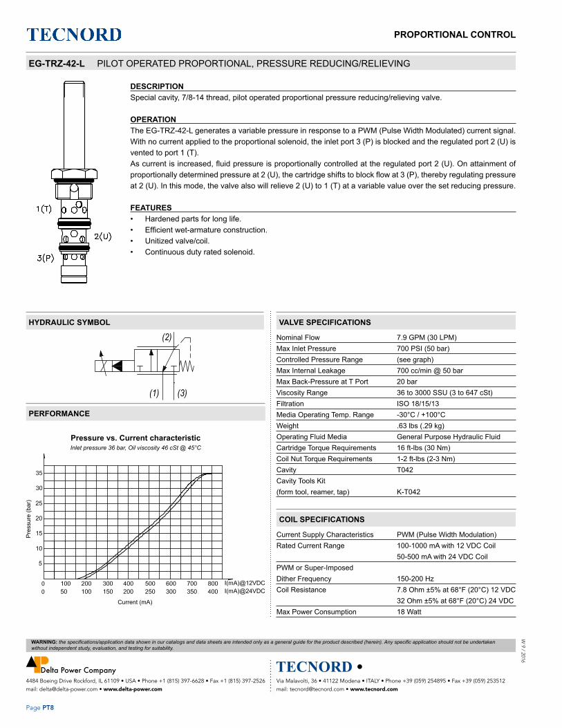
EG-TRZ-42-L PILOT OPERATED PROPORTIONAL, PRESSURE REDUCING/RELIEVING
DESCRIPTIONSpecial cavity, 7/8-14 thread, pilot operated proportional pressure reducing/relieving valve.
OPERATIONThe EG-TRZ-42-L generates a variable pressure in response to a PWM (Pulse Width Modulated) current signal. With no current applied to the proportional solenoid, the inlet port 3 (P) is blocked and the regulated port 2 (U) is vented to port 1 (T). As current is increased, fluid pressure is proportionally controlled at the regulated port 2 (U). On attainment of proportionally determined pressure at 2 (U), the cartridge shifts to block flow at 3 (P), thereby regulating pressure at 2 (U). In this mode, the valve also will relieve 2 (U) to 1 (T) at a variable value over the set reducing pressure.
FEATURES • Hardened parts for long life.• Efficient wet-armature construction.• Unitized valve/coil.• Continuous duty rated solenoid.
Nominal Flow 7.9 GPM (30 LPM) Max Inlet Pressure 700 PSI (50 bar)Controlled Pressure Range (see graph)Max Internal Leakage 700 cc/min @ 50 barMax Back-Pressure at T Port 20 barViscosity Range 36 to 3000 SSU (3 to 647 cSt)Filtration ISO 18/15/13Media Operating Temp. Range -30°C / +100°CWeight .63 lbs (.29 kg)Operating Fluid Media General Purpose Hydraulic FluidCartridge Torque Requirements 16 ft-lbs (30 Nm)Coil Nut Torque Requirements 1-2 ft-lbs (2-3 Nm)Cavity T042Cavity Tools Kit(form tool, reamer, tap) K-T042
VALVE SPECIFICATIONS
Current Supply Characteristics PWM (Pulse Width Modulation)Rated Current Range 100-1000 mA with 12 VDC Coil 50-500 mA with 24 VDC CoilPWM or Super-ImposedDither Frequency 150-200 HzCoil Resistance 7.8 Ohm ±5% at 68°F (20°C) 12 VDC 32 Ohm ±5% at 68°F (20°C) 24 VDCMax Power Consumption 18 Watt
COIL SPECIFICATIONS
HYDRAULIC SYMBOL
PERFORMANCE
Pre
ssur
e (b
ar)
Current (mA)
Pressure vs. Current characteristicInlet pressure 36 bar, Oil viscosity 46 cSt @ 45°C

Via Malavolti, 36 • 41122 Modena • ITALY • Phone +39 (059) 254895 • Fax +39 (059) 253512 mail: [email protected] • www.tecnord.com
4484 Boeing Drive Rockford, IL 61109 • USA • Phone +1 (815) 397-6628 • Fax +1 (815) 397-2526 mail: [email protected] • www.delta-power.com
WARNING: the specifications/application data shown in our catalogs and data sheets are intended only as a general guide for the product described (herein). Any specific application should not be undertaken without independent study, evaluation, and testing for suitability.
Page PT9
PROPORTIONAL CONTROLW
9 /
201
6
DIMENSIONS
ORDERING INFORMATIONApproximate Coil Weight: .42 lbs (.19 kg)
Pre
ssur
e D
rop
(bar
)
Flow (LPM)
Pressure Drop vs. Flow characteristicOil viscosity 46 cSt @ 45°C
MAX REGULATEDPRESSURE
OPTIONS “A” COIL TERMINATION
VOLTAGE BODIES
35 bar 00 - Buna Standard DL - Double Lead 12 - 12 VDC Blank - Without body
A0 - Buna Screen HC - DIN 43650 (Hirschmann)
24 - 24 VDC N - 3/8” BSP Ports
JT - AMP Jr. Timer
DT - Deutsch DT04 Horizontal
EG-TRZ-42-L - – – – –

Via Malavolti, 36 • 41122 Modena • ITALY • Phone +39 (059) 254895 • Fax +39 (059) 253512 mail: [email protected] • www.tecnord.com
4484 Boeing Drive Rockford, IL 61109 • USA • Phone +1 (815) 397-6628 • Fax +1 (815) 397-2526 mail: [email protected] • www.delta-power.com
WARNING: the specifications/application data shown in our catalogs and data sheets are intended only as a general guide for the product described (herein). Any specific application should not be undertaken without independent study, evaluation, and testing for suitability.
Page PT10
PROPORTIONAL CONTROLW
9 / 2016
EG-TRZ-42-H PILOT OPERATED PROPORTIONAL, PRESSURE REDUCING/RELIEVING
DESCRIPTIONSpecial cavity, 7/8-14 thread, pilot operated proportional pressure reducing/relieving valve.
OPERATIONThe EG-TRZ-42-H generates a variable pressure in response to a PWM (Pulse Width Modulated) current signal. With no current applied to the proportional solenoid, the inlet port 3 (P) is blocked and the regulated port 2 (U) is vented to port 1 (T). As current is increased, fluid pressure is proportionally controlled at the regulated port 2 (U). On attainment of proportionally determined pressure at 2 (U), the cartridge shifts to block flow at 3 (P), thereby regulating pressure at 2 (U). In this mode, the valve also will relieve 2 (U) to 1 (T) at a variable value over the set reducing pressure.
FEATURES • Hardened parts for long life.• Efficient wet-armature construction.• Unitized valve/coil.• Continuous duty rated solenoid.
Nominal Flow 7.9 GPM (30 LPM) Max Inlet Pressure 3500 PSI (241 bar)Controlled Pressure Range (see graph)Max Internal Leakage 1500 ml/min @ 200 bar inlet pressureMax Back-Pressure at T Port 20 barViscosity Range 36 to 3000 SSU (3 to 647 cSt)Filtration ISO 18/15/13Media Operating Temp. Range -30°C / +100°CWeight .63 lbs (.29 kg)Operating Fluid Media General Purpose Hydraulic FluidCartridge Torque Requirements 16 ft-lbs (30 Nm)Coil Nut Torque Requirements 1-2 ft-lbs (2-3 Nm)Cavity T042Cavity Tools Kit(form tool, reamer, tap) K-T042
VALVE SPECIFICATIONS
Current Supply Characteristics PWM (Pulse Width Modulation)Rated Current Range 100-1200 mA with 12 VDC Coil 50-600 mA with 24 VDC CoilPWM or Super-ImposedDither Frequency 150-200 HzCoil Resistance 6.85 Ohm ±5% at 68°F (20°C) 12 VDC 27 Ohm ±5% at 68°F (20°C) 24 VDCMax Power Consumption 21 Watt
COIL SPECIFICATIONS
HYDRAULIC SYMBOL
PERFORMANCE
Pre
ssur
e (b
ar)
Current (mA)
Pressure vs. Current characteristicOil viscosity 46 cSt @ 45°C

Via Malavolti, 36 • 41122 Modena • ITALY • Phone +39 (059) 254895 • Fax +39 (059) 253512 mail: [email protected] • www.tecnord.com
4484 Boeing Drive Rockford, IL 61109 • USA • Phone +1 (815) 397-6628 • Fax +1 (815) 397-2526 mail: [email protected] • www.delta-power.com
WARNING: the specifications/application data shown in our catalogs and data sheets are intended only as a general guide for the product described (herein). Any specific application should not be undertaken without independent study, evaluation, and testing for suitability.
Page PT11
PROPORTIONAL CONTROLW
9 /
201
6
DIMENSIONS
ORDERING INFORMATIONApproximate Coil Weight: .42 lbs (.19 kg)
MAX REGULATEDPRESSURE
OPTIONS “PJ” COIL TERMINATION
VOLTAGE BODIES
140 bar 00 - Polyurethane Standard
DL - Double Lead 12 - 12 VDC Blank - Without body
210 bar HC - DIN 43650 (Hirschmann)
24 - 24 VDC N - 3/8” BSP Ports
JT - AMP Jr. Timer
DT - Deutsch DT04 Horizontal
EG-TRZ-42-H - – – – –
Pre
ssur
e D
rop
(bar
)
Flow (LPM)
Pressure Drop vs. Flow characteristicOil viscosity 46 cSt @ 45°C

PROPORTIONAL CONTROL
Page PT12
W 9 / 2016
Via Malavolti, 36 • 41122 Modena • ITALY • Phone +39 (059) 254895 • Fax +39 (059) 253512 mail: [email protected] • www.tecnord.com
4484 Boeing Drive Rockford, IL 61109 • USA • Phone +1 (815) 397-6628 • Fax +1 (815) 397-2526 mail: [email protected] • www.delta-power.com
WARNING: the specifications/application data shown in our catalogs and data sheets are intended only as a general guide for the product described (herein). Any specific application should not be undertaken without independent study, evaluation, and testing for suitability.

PROPORTIONAL CONTROLW
9 /
201
6
Page PT13
Via Malavolti, 36 • 41122 Modena • ITALY • Phone +39 (059) 254895 • Fax +39 (059) 253512 mail: [email protected] • www.tecnord.com
4484 Boeing Drive Rockford, IL 61109 • USA • Phone +1 (815) 397-6628 • Fax +1 (815) 397-2526 mail: [email protected] • www.delta-power.com
WARNING: the specifications/application data shown in our catalogs and data sheets are intended only as a general guide for the product described (herein). Any specific application should not be undertaken without independent study, evaluation, and testing for suitability.
NORMALLY CLOSED GPM PSI LPM BAR CAVITY MODEL PAGE
12 3000 45 207 7/8-14 EE-PRB PT14
PROPORTIONAL PRESSURE RELIEF VALVES
NORMALLY OPEN GPM PSI LPM BAR CAVITY MODEL PAGE
12 3000 45 207 7/8-14 EE-PRD PT16
Typical application for the PRL and PRB is for fan or motor speed control.
TYPICAL SCHEMATIC

Via Malavolti, 36 • 41122 Modena • ITALY • Phone +39 (059) 254895 • Fax +39 (059) 253512 mail: [email protected] • www.tecnord.com
4484 Boeing Drive Rockford, IL 61109 • USA • Phone +1 (815) 397-6628 • Fax +1 (815) 397-2526 mail: [email protected] • www.delta-power.com
WARNING: the specifications/application data shown in our catalogs and data sheets are intended only as a general guide for the product described (herein). Any specific application should not be undertaken without independent study, evaluation, and testing for suitability.
Page PT14
PROPORTIONAL CONTROLW
9 / 2016
EE-PRB 2 WAY NORMALLY CLOSED, PROPORTIONAL RELIEF VALVE
DESCRIPTION10 size, 7/8-14 thread, “Delta” series, solenoid operated, 2 way normally closed, pilot operated spool type relief valve.
OPERATIONThe EE-PRB blocks flow from (2) to (1) until sufficient pressure is present at (2) to offset a spring induced force. As solenoid current is increased, it offsets a portion of this force, resulting in a lower relief pressure. Can be infinitely adjusted across a prescribed range in response to a PWM (Pulse Width Modulated) current. Pressure output is inversely proportional to the current input. With full current applied to the solenoid, the valve will free flow from (2) to (1), at approximately 100 PSI (7 bar).Note: backpressure on port (1) becomes additive to the pressure setting at a 1:1 ratio.
FEATURES • Efficient wet-armature construction.• Cartridges are voltage interchangeable.• Industry common cavity.• Unitized, molded coil design.• Continuous duty rated solenoid.• Optional coil voltages and terminations.
1
2
1
2
Nominal Flow 0÷20 GPM (0÷76 LPM)Operating Range 100-3000 PSI (7-207 bar)Typical Hysteresis 10% MaxViscosity Range 36 to 3000 SSU (3 to 647 cSt)Filtration ISO 18/16/13Media Operating Temp. Range -30°C / +100°CWeight .62 lbs (.28 kg)Operating Fluid Media General Purpose Hydraulic FluidCartridge Torque Requirements 30 ft-lbs (40.6 Nm)Coil Nut Torque Requirements 2-3 ft-lbs (3-4 Nm)Cavity DELTA 2WCavity Tools Kit(form tool, reamer, tap) 40500000Seal Kit 21191202
VALVE SPECIFICATIONS
Current Supply Characteristics PWM (Pulse Width Modulation)Rated Current Range 100÷1000 mAPWM or Super-ImposedDither Frequency 120÷200 HzCoil Resistance (12 VDC) 7.2 Ohm ±5% at 68°F (20°C)
COIL SPECIFICATIONS
Great for fan drive motor control.
HYDRAULIC SYMBOL
PERFORMANCE
Rel
ief P
ress
ure
(bar
)
Current (mA)Coil 12 VDC
Relief pressure vs. CurrentCostant flow 10 LPM (2.6 GPM)

Via Malavolti, 36 • 41122 Modena • ITALY • Phone +39 (059) 254895 • Fax +39 (059) 253512 mail: [email protected] • www.tecnord.com
4484 Boeing Drive Rockford, IL 61109 • USA • Phone +1 (815) 397-6628 • Fax +1 (815) 397-2526 mail: [email protected] • www.delta-power.com
WARNING: the specifications/application data shown in our catalogs and data sheets are intended only as a general guide for the product described (herein). Any specific application should not be undertaken without independent study, evaluation, and testing for suitability.
Page PT15
PROPORTIONAL CONTROLW
9 /
201
6
(for bodies style and sizes see section “Accessories”)0,
87 [
22]
Hex
.
3,58
[91
]1,
25 [
31,8
]
1,97
[50
]
Hex. 1,06 [27]
7/8-14 UNF - 2A
1,46 [37]
1,04 [26,5]
1,77 [45]
SEE COIL DATA FOR TERMINATIONS
DIMENSIONS
ORDERING INFORMATION
OPTIONS BODIESBuna, 100-1015 PSI range (7-70 bar) 0A Blank Without BodyViton, 100-1015 PSI range (7-70 bar) VA N 3/8” BSP Ports
S #8 SAE PortsBuna, 100-2175 PSI range (7-150 bar) 0BViton, 100-2175 PSI range (7-150 bar) VB
Buna, 100-3000 PSI range (7-207 bar) 0CViton, 100-3000 PSI range (7-207 bar) VC VOLTAGE (other voltages available on request)
12 12 VDC24 24 VDC
“F” COIL TERMINATION
DIN 43650 (Hirschmann) HCDeutsch - Integral DT04-2P DI
AMP Jr. Timer JT
EE-PRB – – – – Approximate Coil Weight: .47 lbs (.21 kg)
Great for fan drive motor control. 1
2
1
2
Rel
ief P
ress
ure
(bar
)R
elie
f Pre
ssur
e (b
ar)
Rel
ief P
ress
ure
(PS
I)R
elie
f Pre
ssur
e (P
SI)
Flow (LPM)
Flow (GPM)
Flow (GPM)
Flow (LPM)
Relief pressure vs. Flow - No current appliedCostant flow 10 LPM (2.6 GPM)
Pressure Drop vs. FlowCoil energized

Via Malavolti, 36 • 41122 Modena • ITALY • Phone +39 (059) 254895 • Fax +39 (059) 253512 mail: [email protected] • www.tecnord.com
4484 Boeing Drive Rockford, IL 61109 • USA • Phone +1 (815) 397-6628 • Fax +1 (815) 397-2526 mail: [email protected] • www.delta-power.com
WARNING: the specifications/application data shown in our catalogs and data sheets are intended only as a general guide for the product described (herein). Any specific application should not be undertaken without independent study, evaluation, and testing for suitability.
Page PT16
PROPORTIONAL CONTROLW
9 / 2016
EE-PRD 2 WAY NORMALLY OPEN, PROPORTIONAL RELIEF VALVE
DESCRIPTION10 size, 7/8-14 thread, “Delta” series, solenoid operated, 2 way normally open, pilot operated spool typerelief valve.
OPERATIONThe EE-PRD blocks flow from (2) to (1) until sufficient pressure is present at (2) to offset the electrically induced solenoid force. Can be infinitely adjusted across a prescribed range in response to a PWM (Pulse Width Modulated) current. Pressure output is proportional to the current input.With no current applied to the solenoid, the valve will free flow from (2) to (1) at approximately 50 PSI.Note: backpressure on port (1) becomes additive to the pressure setting at a 1:1 ratio.
FEATURES • Efficient wet-armature construction.• Cartridges are voltage interchangeable.• Industry common cavity.• Unitized, molded coil design.• Continuous duty rated solenoid.• Optional coil voltages and terminations.
Nominal Flow 0-12 GPM (0-45 LPM)Operating Range 50-3000 PSI (3-207 bar)Typical Hysteresis 5%Viscosity Range 36 to 3000 SSU (3 to 647 cSt)Filtration ISO 18/16/13Media Operating Temp. Range -30°C / +100°CWeight .30 lbs (.13 kg)Operating Fluid Media General Purpose Hydraulic FluidCartridge Torque Requirements 30 ft-lbs (40.6 Nm)Coil Nut Torque Requirements 4-6 ft-lbs (5.4-8.1 Nm)Cavity DELTA 2WCavity Tools Kit(form tool, reamer, tap) 40500000Seal Kit 21191202
Current Supply Characteristics PWM (Pulse Width Modulation)Rated Current Range 200-1500 mAPWM or Super-Imposed Dither Frequency 500 HzCoil Resistance (12 VDC) 5.9 Ohm ±5% at 68°F (20°C)
VALVE SPECIFICATIONS
COIL SPECIFICATIONS
For best performance valve must be purged of air. Locate below reservoir or add check valve to return.
HYDRAULIC SYMBOL
PERFORMANCE
Pre
ssur
e (P
SI)
Pre
ssur
e (b
ar)
Current (mA) using 24 VDC Coil

Via Malavolti, 36 • 41122 Modena • ITALY • Phone +39 (059) 254895 • Fax +39 (059) 253512 mail: [email protected] • www.tecnord.com
4484 Boeing Drive Rockford, IL 61109 • USA • Phone +1 (815) 397-6628 • Fax +1 (815) 397-2526 mail: [email protected] • www.delta-power.com
WARNING: the specifications/application data shown in our catalogs and data sheets are intended only as a general guide for the product described (herein). Any specific application should not be undertaken without independent study, evaluation, and testing for suitability.
Page PT17
PROPORTIONAL CONTROLW
9 /
201
6
OPTIONS BODIESBuna Standard 00 Blank Without BodyViton Standard V0 N 3/8” BSP Ports
S #8 SAE Ports
VOLTAGE12 12 VDC24 24 VDC
“V” COIL TERMINATIONHC DIN 43650 (Hirschmann)DI Deutsch - Integral DT04-2PDL Double LeadJT AMP Jr. Timer - Integral
EE-PRD – – – –
(for bodies style and sizes see section “Accessories”)
DIMENSIONS
ORDERING INFORMATIONApproximate Coil Weight: .42 lbs (.19 kg)

PROPORTIONAL CONTROL
Page PT18
W 9 / 2016
Via Malavolti, 36 • 41122 Modena • ITALY • Phone +39 (059) 254895 • Fax +39 (059) 253512 mail: [email protected] • www.tecnord.com
4484 Boeing Drive Rockford, IL 61109 • USA • Phone +1 (815) 397-6628 • Fax +1 (815) 397-2526 mail: [email protected] • www.delta-power.com
WARNING: the specifications/application data shown in our catalogs and data sheets are intended only as a general guide for the product described (herein). Any specific application should not be undertaken without independent study, evaluation, and testing for suitability.

PROPORTIONAL CONTROLW
9 /
201
6
Page PT19
Via Malavolti, 36 • 41122 Modena • ITALY • Phone +39 (059) 254895 • Fax +39 (059) 253512 mail: [email protected] • www.tecnord.com
4484 Boeing Drive Rockford, IL 61109 • USA • Phone +1 (815) 397-6628 • Fax +1 (815) 397-2526 mail: [email protected] • www.delta-power.com
WARNING: the specifications/application data shown in our catalogs and data sheets are intended only as a general guide for the product described (herein). Any specific application should not be undertaken without independent study, evaluation, and testing for suitability.
SPOOL TYPE GPM PSI LPM BAR CAVITY MODEL PAGE
13.2 3500 50 245 7/8-14 EE-P2G PT20
23.7 3500 90 245 1 1/16-12 ET-P2S PT22
2 WAY NORMALLY CLOSED PROPORTIONAL FLOW REGULATOR VALVES
POPPET TYPE GPM PSI LPM BAR CAVITY MODEL PAGE
6.5 3500 25 245 3/4-16 EB-P2A PT24
12 3500 45 245 7/8-14 EE-P2A PT26
29 3500 110 245 1 1/16-12 ET-P2A PT28

Via Malavolti, 36 • 41122 Modena • ITALY • Phone +39 (059) 254895 • Fax +39 (059) 253512 mail: [email protected] • www.tecnord.com
4484 Boeing Drive Rockford, IL 61109 • USA • Phone +1 (815) 397-6628 • Fax +1 (815) 397-2526 mail: [email protected] • www.delta-power.com
WARNING: the specifications/application data shown in our catalogs and data sheets are intended only as a general guide for the product described (herein). Any specific application should not be undertaken without independent study, evaluation, and testing for suitability.
Page PT20
PROPORTIONAL CONTROLW
9 / 2016
Flow vs. Current - “A” VersionCoil 12 VDC - Delta P = 14 bar - Oil 26 cSt (121 SSU) @ 50°C (104°F)
Q (l/min)
l (mA)
EE-P2G 2 WAY NORMALLY CLOSED, PROPORTIONAL FLOW CONTROL VALVE
DESCRIPTION10 size, 7/8-14 thread, “Delta” series, solenoid operated, 2 way normally closed, proportional flow controlvalve.
OPERATIONWhen de-energized the EE-P2G blocks flow at ports (1) and (2). When energized, the valve allows flow from (2) to (1). Flow is proportional to the current applied to the coil. A compensator must be used to create a pressure compensated flow control function.OPERATION OF MANUAL OVERRIDE OPTION: to override, turn the manual override screw clockwise. To release turn the manual override screw counterclockwise.
FEATURES • Efficient wet-armature construction.• Cartridges are voltage interchangeable.• Industry common cavity.• Unitized, molded coil design.• Continuous duty rated solenoid.• Optional coil voltages and terminations.
Flow Range See curves for various versionsMax System Pressure 3500 PSI (245 bar)Leakage Max 50 cc/min at 245 barHysteresis ±3%Viscosity Range 36 to 3000 SSU (3 to 647 cSt)Filtration ISO 18/16/13Media Operating Temp. Range -30°C / +100°CWeight .58 lbs (.26 kg)Operating Fluid Media General Purpose Hydraulic FluidCartridge Torque Requirements 26 ft-lbs (35 Nm)Coil Nut Torque Requirements 2-3 ft-lbs (3-4 Nm)Cavity DELTA 2WCavity Tools Kit(form tool, reamer, tap) 40500000Seal Kit 21191200
Current Supply Characteristics PWM (Pulse Width Modulation)Rated Current Range 400-1400 mAPWM or Super-ImposedDither Frequency 100-150 HzCoil Resistance (12 VDC) 7.2 Ohm ±5% at 68°F (20°C)
HYDRAULIC SYMBOL
PERFORMANCE
VALVE SPECIFICATIONS
COIL SPECIFICATIONS
Curves are attained with Tecnord QC-CP3 compensator.

Via Malavolti, 36 • 41122 Modena • ITALY • Phone +39 (059) 254895 • Fax +39 (059) 253512 mail: [email protected] • www.tecnord.com
4484 Boeing Drive Rockford, IL 61109 • USA • Phone +1 (815) 397-6628 • Fax +1 (815) 397-2526 mail: [email protected] • www.delta-power.com
WARNING: the specifications/application data shown in our catalogs and data sheets are intended only as a general guide for the product described (herein). Any specific application should not be undertaken without independent study, evaluation, and testing for suitability.
Page PT21
PROPORTIONAL CONTROLW
9 /
201
6
EE-P2G – – – –
NOTES: 1) Flows refer to a 14 bar Delta P 2) For other seals, consult factory
OPTIONS BODIESBuna, Push Type Override Standard AP Up to 22 l/min Blank Without Body
Buna, Screw Type Override (Knob) AS Up to 22 l/min N 3/4” BSP PortsBuna, Screw Type Override (Grad. Knob) AK Up to 22 l/min S #8 SAE Ports
Buna, Push Type Override Standard BP Up to 50 l/minBuna, Screw Type Override (Knob) BS Up to 50 l/min
Buna, Screw Type Override (Grad. Knob) BK Up to 50 l/min VOLTAGE12 12 VDC
Buna, Push Type Override Standard CP Up to 50 l/min 24 24 VDCBuna, Screw Type Override (Knob) CS Up to 50 l/min “F” COIL TERMINATION
Buna, Screw Type Override (Grad. Knob) CK Up to 50 l/min HC DIN 43650 (Hirschmann)DI Deutsch-Integral DT04-2PJT AMP Jr. Timer
Flow vs. Current - “C” VersionCoil 12 VDC - Delta P = 14 bar - Oil 26 cSt (121 SSU) @ 50°C (104°F)
(for bodies style and sizes see section “Accessories”)
DIMENSIONS
ORDERING INFORMATIONApproximate Coil Weight: .47 lbs (.21 kg)
Q (l/min)
l (mA)
NOTE: non linear
characteristics
Flow vs. Current - “B” VersionCoil 12 VDC - Delta P = 14 bar - Oil 26 cSt (121 SSU) @ 50°C (104°F)
Q (l/min)
l (mA)

Via Malavolti, 36 • 41122 Modena • ITALY • Phone +39 (059) 254895 • Fax +39 (059) 253512 mail: [email protected] • www.tecnord.com
4484 Boeing Drive Rockford, IL 61109 • USA • Phone +1 (815) 397-6628 • Fax +1 (815) 397-2526 mail: [email protected] • www.delta-power.com
WARNING: the specifications/application data shown in our catalogs and data sheets are intended only as a general guide for the product described (herein). Any specific application should not be undertaken without independent study, evaluation, and testing for suitability.
Page PT22
PROPORTIONAL CONTROLW
9 / 2016
ET-P2S 2 WAY NORMALLY CLOSED, PROPORTIONAL FLOW CONTROL VALVE
DESCRIPTION12 size, 1 1/16-12 thread, “Tecnord” series, solenoid operated, 2 way normally closed, proportional flow controlvalve.
OPERATIONWhen de-energized the ET-P2S blocks flow at ports (2) and (1). When energized, the valve allows flow from (1) to (2). Flow is proportional to the current applied to the coil. A compensator must be used to create a pressure compensated flow control function.OPERATION OF MANUAL OVERRIDE OPTION: to override, turn the manual override screw counterclockwise. To release turn the manual override screw clockwise.
FEATURES • Efficient wet-armature construction.• Cartridges are voltage interchangeable.• Industry common cavity.• Unitized, molded coil design.• Continuous duty rated solenoid.• Optional coil voltages and terminations.
Flow Range See curves for various versionsMax System Pressure 3500 PSI (245 bar)Leakage Max 50 cc/min at 245 barHysteresis ±3%Viscosity Range 36 to 3000 SSU (3 to 647 cSt)Filtration ISO 18/16/13Media Operating Temp. Range -30°C / +100°CWeight .72 lbs (.32 kg)Operating Fluid Media General Purpose Hydraulic FluidCartridge Torque Requirements 37 ft-lbs (50 Nm)Coil Nut Torque Requirements 2-3 ft-lbs (3-4 Nm)Cavity TECNORD 2WCavity Tools Kit(form tool, reamer, tap) 40500032Seal Kit 21191200
Current Supply Characteristics PWM (Pulse Width Modulation)Rated Current Range 400-1400 mAPWM or Super-ImposedDither Frequency 100-150 HzCoil Resistance (12 VDC) 7.2 Ohm ±5% at 68°F (20°C)
VALVE SPECIFICATIONS
COIL SPECIFICATIONS
Curves are attained with Tecnord QC-CP3 compensator.
HYDRAULIC SYMBOL
PERFORMANCE
Flow vs. Current Coil 12 VDC - Press. Drop = 14 bar - Oil 46 cSt (217 SSU) @ 50°C (122°F)
Flow
(LP
M)
Flow
(GP
M)
Current (mA)

Via Malavolti, 36 • 41122 Modena • ITALY • Phone +39 (059) 254895 • Fax +39 (059) 253512 mail: [email protected] • www.tecnord.com
4484 Boeing Drive Rockford, IL 61109 • USA • Phone +1 (815) 397-6628 • Fax +1 (815) 397-2526 mail: [email protected] • www.delta-power.com
WARNING: the specifications/application data shown in our catalogs and data sheets are intended only as a general guide for the product described (herein). Any specific application should not be undertaken without independent study, evaluation, and testing for suitability.
Page PT23
PROPORTIONAL CONTROLW
9 /
201
6
UNF
DIMENSIONS
ET-P2S – – – –
NOTES: 1) Flows refer to a 14 bar Delta P 2) For other seals, consult factory
OPTIONS BODIESBuna Standard C0 Up to 90 l/min Blank Without Body
Buna, Screw Type Override (Knob) CS Up to 90 l/min N 3/4” BSP PortsBuna, Screw Type Override (Grad. Knob) CK Up to 90 l/min S #8 SAE Ports
VOLTAGE12 12 VDC24 24 VDC
“F” COIL TERMINATIONHC DIN 43650 (Hirschmann)DI Deutsch-Integral DT04-2PJT AMP Jr. Timer
(for bodies style and sizes see section “Accessories”)
ORDERING INFORMATIONApproximate Coil Weight: .47 lbs (.21 kg)
Pressure Drop With valve fully open - Oil 46 cSt (217 SSU) @ 50°C (122°F)
Pre
ssur
e D
rop
(bar
)
Pre
ssur
e D
rop
(PS
I)
Flow (LPM)
Flow (GPM)

Via Malavolti, 36 • 41122 Modena • ITALY • Phone +39 (059) 254895 • Fax +39 (059) 253512 mail: [email protected] • www.tecnord.com
4484 Boeing Drive Rockford, IL 61109 • USA • Phone +1 (815) 397-6628 • Fax +1 (815) 397-2526 mail: [email protected] • www.delta-power.com
WARNING: the specifications/application data shown in our catalogs and data sheets are intended only as a general guide for the product described (herein). Any specific application should not be undertaken without independent study, evaluation, and testing for suitability.
Page PT24
PROPORTIONAL CONTROLW
9 / 2016
EB-P2A 2 WAY NORMALLY CLOSED, PROPORTIONAL FLOW CONTROL VALVE
DESCRIPTION8 size, 3/4-16 thread, solenoid operated, 2 way normally closed poppet style, proportional flow control valve.
OPERATIONWhen de-energized the EB-P2A blocks flow from (1) to (2) and allows reverse flow from (2) to (1). When energized, the valve allows flow from (1) to (2). Flow is proportional to current applied to the coil. A compensator must be used to create a pressure compensated flow control function.
FEATURES • Efficient wet-armature construction.• Cartridges are voltage interchangeable.• Industry common cavity.• Unitized, molded coil design.• Continuous duty rated solenoid.• Optional coil voltages and terminations.
Flow Range See curvesMax System Pressure 3500 PSI (245 bar)Leakage 0-10 drops / min @ 245 barHysteresis ±3%Viscosity Range 36 to 3000 SSU (3 to 647 cSt)Filtration ISO 18/16/13Media Operating Temp. Range -30°C / +100°CWeight .72 lbs (.32 kg)Operating Fluid Media General Purpose Hydraulic FluidCartridge Torque Requirements 19 ft-lbs (25 Nm)Coil Nut Torque Requirements 2-3 ft-lbs (3-4 Nm)Cavity POWER 2WCavity Tools Kit(form tool, reamer, tap) 40500005Seal Kit 21191102
Current Supply Characteristics PWM (Pulse Width Modulation)Rated Current Range 400-1400 mAPWM or Super-Imposed Dither Frequency 100 HzCoil Resistance (12 VDC) 7.2 Ohm ±5% at 68°F (20°C)
Pressure Drop 1 to 2 with valve completely open
Flow vs. Current at different Pressure DropCoil 12 VDC - hyd. - Oil 26 cSt (121 SSU) @ 40°C (104°F)
VALVE SPECIFICATIONS
COIL SPECIFICATIONS
Curves are attained without pressure compensator. The valve can work with a pressure drop up to 200 bar.
HYDRAULIC SYMBOL
PERFORMANCE
Pre
ssur
e D
rop
(bar
)
Pre
ssur
e D
rop
(PS
I)
Flow (l/min)
Current (Amps)
Flow
(l/m
in)
Flow
(GP
M)
Flow (GPM)

Via Malavolti, 36 • 41122 Modena • ITALY • Phone +39 (059) 254895 • Fax +39 (059) 253512 mail: [email protected] • www.tecnord.com
4484 Boeing Drive Rockford, IL 61109 • USA • Phone +1 (815) 397-6628 • Fax +1 (815) 397-2526 mail: [email protected] • www.delta-power.com
WARNING: the specifications/application data shown in our catalogs and data sheets are intended only as a general guide for the product described (herein). Any specific application should not be undertaken without independent study, evaluation, and testing for suitability.
Page PT25
PROPORTIONAL CONTROLW
9 /
201
6
DIMENSIONS
EB-P2A – – – –
NOTES: 1) Flows refer to a 14 bar Delta P 2) For other seals, consult factory
OPTIONS BODIESBuna Standard C0 Up to 25 l/min Blank Without Body
Buna, Screw Type Override (Knob) CS Up to 25 l/min N 3/8” BSP PortsBuna, Screw Type Override (Grad. Knob) CK Up to 25 l/min S #8 SAE Ports
VOLTAGE12 12 VDC24 24 VDC
“F” COIL TERMINATIONHC DIN 43650 (Hirschmann)DI Deutsch-Integral DT04-2PJT AMP Jr. Timer
(for bodies style and sizes see section “Accessories”)
ORDERING INFORMATIONApproximate Coil Weight: .47 lbs (.21 kg)

Via Malavolti, 36 • 41122 Modena • ITALY • Phone +39 (059) 254895 • Fax +39 (059) 253512 mail: [email protected] • www.tecnord.com
4484 Boeing Drive Rockford, IL 61109 • USA • Phone +1 (815) 397-6628 • Fax +1 (815) 397-2526 mail: [email protected] • www.delta-power.com
WARNING: the specifications/application data shown in our catalogs and data sheets are intended only as a general guide for the product described (herein). Any specific application should not be undertaken without independent study, evaluation, and testing for suitability.
Page PT26
PROPORTIONAL CONTROLW
9 / 2016
EE-P2A 2 WAY NORMALLY CLOSED, PROPORTIONAL FLOW CONTROL VALVE
DESCRIPTION10 size, 7/8-14 thread, solenoid operated, 2 way normally closed poppet style, proportional flow control valve.
OPERATIONWhen de-energized the EE-P2A blocks flow from (1) to (2) and allows reverse flow from (2) to (1). When energized, the valve allows flow from (1) to (2). Flow is proportional to current applied to the coil. A compensator must be used to create a pressure compensated flow control function.
FEATURES • Efficient wet-armature construction.• Cartridges are voltage interchangeable.• Industry common cavity.• Unitized, molded coil design.• Continuous duty rated solenoid.• Optional coil voltages and terminations.
Flow Range See curves for various versionsMax System Pressure 3500 PSI (245 bar)Leakage 0-10 drops / min @ 245 barHysteresis ±3%Viscosity Range 36 to 3000 SSU (3 to 647 cSt)Filtration ISO 18/16/13Media Operating Temp. Range -30°C / +100°CWeight .72 lbs (.32 kg)Operating Fluid Media General Purpose Hydraulic FluidCartridge Torque Requirements 26-35 ft-lbs (50 Nm)Coil Nut Torque Requirements 2-3 ft-lbs (3-4 Nm)Cavity DELTA 2WCavity Tools Kit(form tool, reamer, tap) 40500000Seal Kit 21191200
Current Supply Characteristics PWM (Pulse Width Modulation)Rated Current Range 400-1400 mAPWM or Super-Imposed Dither Frequency 100 HzCoil Resistance (12 VDC) 7.2 Ohm ±5% at 68°F (20°C)
VALVE SPECIFICATIONS
COIL SPECIFICATIONS
Curves are attained without pressure compensator. The valve can work with a pressure drop up to 200 bar.
HYDRAULIC SYMBOL
PERFORMANCE
Pressure Drop 1 to 2 with valve completely open
Flow vs. Current at different Pressure DropPoppet type A - Coil 12 VDC - hyd. oil 26 cSt (121 SSU) @ 40°C (104°F)
Pre
ssur
e D
rop
(bar
)
Pre
ssur
e D
rop
(PS
I)
Flow (l/min)
Current (Amps)
Flow
(l/m
in)
Flow
(GP
M)
Flow (GPM)

Via Malavolti, 36 • 41122 Modena • ITALY • Phone +39 (059) 254895 • Fax +39 (059) 253512 mail: [email protected] • www.tecnord.com
4484 Boeing Drive Rockford, IL 61109 • USA • Phone +1 (815) 397-6628 • Fax +1 (815) 397-2526 mail: [email protected] • www.delta-power.com
WARNING: the specifications/application data shown in our catalogs and data sheets are intended only as a general guide for the product described (herein). Any specific application should not be undertaken without independent study, evaluation, and testing for suitability.
Page PT27
PROPORTIONAL CONTROLW
9 /
201
6
DIMENSIONS
ORDERING INFORMATION
EE-P2A – – – –
NOTES: 1) Flows refer to a 14 bar Delta P 2) For other seals, consult factory
OPTIONS BODIESBuna Standard A0 Up to 15 l/min Blank Without Body
Buna, Screw Type Override (Knob) AS Up to 15 l/min N 3/4” BSP PortsBuna, Screw Type Override (Grad. Knob) AK Up to 15 l/min S #8 SAE Ports
Buna Standard B0 Up to 30 l/minBuna, Screw Type Override (Knob) BS Up to 30 l/min
Buna, Screw Type Override (Grad. Knob) BK Up to 30 l/min VOLTAGE12 12 VDC
Buna Standard C0 Up to 45 l/min 24 24 VDCBuna, Screw Type Override (Knob) CS Up to 45 l/min “F” COIL TERMINATION
Buna, Screw Type Override (Grad. Knob) CK Up to 45 l/min HC DIN 43650 (Hirschmann)DI Deutsch-Integral DT04-2PJT AMP Jr. Timer
Approximate Coil Weight: .47 lbs (.21 kg)
(for bodies style and sizes see section “Accessories”)
Flow vs. Current at different Pressure DropPoppet type B - Coil 12 VDC - hyd. oil 26 cSt (121 SSU) @ 40°C (104°F)
Flow vs. Current at different Pressure DropPoppet type C - Coil 12 VDC - hyd. oil 26 cSt (121 SSU) @ 40°C (104°F)
Current (Amps)
Current (Amps)
Flow
(l/m
in)
Flow
(GP
M)
Flow
(l/m
in)
Flow
(GP
M)

Via Malavolti, 36 • 41122 Modena • ITALY • Phone +39 (059) 254895 • Fax +39 (059) 253512 mail: [email protected] • www.tecnord.com
4484 Boeing Drive Rockford, IL 61109 • USA • Phone +1 (815) 397-6628 • Fax +1 (815) 397-2526 mail: [email protected] • www.delta-power.com
WARNING: the specifications/application data shown in our catalogs and data sheets are intended only as a general guide for the product described (herein). Any specific application should not be undertaken without independent study, evaluation, and testing for suitability.
Page PT28
PROPORTIONAL CONTROLW
9 / 2016
ET-P2A 2 WAY NORMALLY CLOSED, PROPORTIONAL FLOW CONTROL VALVE
DESCRIPTION12 size, 1 1/16-12 thread, solenoid operated, 2 way normally closed poppet style, proportional flow control valve.
OPERATIONWhen de-energized the ET-P2A blocks flow from (1) to (2) and allows reverse flow from (2) to (1). When energized, the valve allows flow from (1) to (2). Flow is proportional to current applied to the coil. A compensator must be used to create a pressure compensated flow control function.
FEATURES • Efficient wet-armature construction.• Cartridges are voltage interchangeable.• Industry common cavity.• Unitized, molded coil design.• Continuous duty rated solenoid.• Optional coil voltages and terminations.
Flow vs. Current
Flow Range See curves for various versionsMax System Pressure 3500 PSI (245 bar)Leakage 0-10 drops / min @ 245 barHysteresis ±3%Viscosity Range 36 to 3000 SSU (3 to 647 cSt)Filtration ISO 18/16/13Media Operating Temp. Range -30°C / +100°CWeight .72 lbs (.32 kg)Operating Fluid Media General Purpose Hydraulic FluidCartridge Torque Requirements 37 ft-lbs (50 Nm)Coil Nut Torque Requirements 2-3 ft-lbs (3-4 Nm)Cavity TECNORD 2WCavity Tools Kit(form tool, reamer, tap) 40500032Seal Kit 21191200
Current Supply Characteristics PWM (Pulse Width Modulation)Rated Current Range 400-1400 mAPWM or Super-Imposed Dither Frequency 100 HzCoil Resistance (12 VDC) 7.2 Ohm ±5% at 68°F (20°C)
VALVE SPECIFICATIONS
COIL SPECIFICATIONS
Curves are attained without pressure compensator. The valve can work with a pressure drop up to 200 bar.
HYDRAULIC SYMBOL
PERFORMANCE
Pressure Drop 1 to 2 with valve completely open
Flow vs. Current at different Pressure DropPoppet type A - Coil 12 VDC - hyd. oil 26 cSt (121 SSU) @ 40°C (104°F)
Pre
ssur
e D
rop
(bar
)
Pre
ssur
e D
rop
(PS
I)
Flow (l/min)
Current (Amps)
Flow
(l/m
in)
Flow
(GP
M)
Flow (GPM)

Via Malavolti, 36 • 41122 Modena • ITALY • Phone +39 (059) 254895 • Fax +39 (059) 253512 mail: [email protected] • www.tecnord.com
4484 Boeing Drive Rockford, IL 61109 • USA • Phone +1 (815) 397-6628 • Fax +1 (815) 397-2526 mail: [email protected] • www.delta-power.com
WARNING: the specifications/application data shown in our catalogs and data sheets are intended only as a general guide for the product described (herein). Any specific application should not be undertaken without independent study, evaluation, and testing for suitability.
Page PT29
PROPORTIONAL CONTROLW
9 /
201
6
(for bodies style and sizes see section “Accessories”)
DIMENSIONS
ORDERING INFORMATION
ET-P2A – – – –
OPTIONS BODIESBuna Standard A0 Up to 65 l/min Blank Without Body
Buna, Screw Type Override (Knob) AS Up to 65 l/min N 3/4” BSP PortsBuna, Screw Type Override (Grad. Knob) AK Up to 65 l/min S #8 SAE Ports
Buna Standard B0 Up to 85 l/minBuna, Screw Type Override (Knob) BS Up to 85 l/min
Buna, Screw Type Override (Grad. Knob) BK Up to 85 l/min VOLTAGE12 12 VDC
Buna Standard C0 Up to 110 l/min 24 24 VDCBuna, Screw Type Override (Knob) CS Up to 110 l/min “F” COIL TERMINATION
Buna, Screw Type Override (Grad. Knob) CK Up to 110 l/min HC DIN 43650 (Hirschmann)DI Deutsch-Integral DT04-2PJT AMP Jr. Timer
Approximate Coil Weight: .47 lbs (.21 kg)
NOTES: 1) Flows refer to a 14 bar Delta P 2) For other seals, consult factory
Flow vs. Current at different Pressure DropPoppet type B - Coil 12 VDC - hyd. oil 26 cSt (121 SSU) @ 40°C (104°F)
Flow vs. Current at different Pressure DropPoppet type C - Coil 12 VDC - hyd. oil 26 cSt (121 SSU) @ 40°C (104°F)
Current (Amps)
Current (Amps)
Flow
(l/m
in)
Flow
(GP
M)
Flow
(l/m
in)
Flow
(GP
M)

PROPORTIONAL CONTROL
Page PT30
W 9 / 2016
Via Malavolti, 36 • 41122 Modena • ITALY • Phone +39 (059) 254895 • Fax +39 (059) 253512 mail: [email protected] • www.tecnord.com
4484 Boeing Drive Rockford, IL 61109 • USA • Phone +1 (815) 397-6628 • Fax +1 (815) 397-2526 mail: [email protected] • www.delta-power.com
WARNING: the specifications/application data shown in our catalogs and data sheets are intended only as a general guide for the product described (herein). Any specific application should not be undertaken without independent study, evaluation, and testing for suitability.

PROPORTIONAL CONTROLW
9 /
201
6
Page PT31
Via Malavolti, 36 • 41122 Modena • ITALY • Phone +39 (059) 254895 • Fax +39 (059) 253512 mail: [email protected] • www.tecnord.com
4484 Boeing Drive Rockford, IL 61109 • USA • Phone +1 (815) 397-6628 • Fax +1 (815) 397-2526 mail: [email protected] • www.delta-power.com
WARNING: the specifications/application data shown in our catalogs and data sheets are intended only as a general guide for the product described (herein). Any specific application should not be undertaken without independent study, evaluation, and testing for suitability.
SPOOL TYPE GPM PSI LPM BAR CAVITY MODEL PAGE
8 3500 30 245 7/8-14 EE-P2H PT32
2 WAY NORMALLY OPEN PROPORTIONAL FLOW CONTROL VALVES

Via Malavolti, 36 • 41122 Modena • ITALY • Phone +39 (059) 254895 • Fax +39 (059) 253512 mail: [email protected] • www.tecnord.com
4484 Boeing Drive Rockford, IL 61109 • USA • Phone +1 (815) 397-6628 • Fax +1 (815) 397-2526 mail: [email protected] • www.delta-power.com
WARNING: the specifications/application data shown in our catalogs and data sheets are intended only as a general guide for the product described (herein). Any specific application should not be undertaken without independent study, evaluation, and testing for suitability.
Page PT32
PROPORTIONAL CONTROLW
9 / 2016
EE-P2H 2 WAY NORMALLY OPEN, PROPORTIONAL FLOW CONTROL VALVE
DESCRIPTION10 size, 7/8-14 thread, solenoid operated, 2 way normally open, proportional flow control valve.
OPERATIONWhen de-energized the EE-P2H allows flow from (1) to (2). When fully energized, the valve blocks flow at port (1) and (2). Flow is proportional to current applied to the coil. A compensator must be used to create a pressure compensated flow control function.OPERATION OF MANUAL OVERRIDE OPTION: to override, turn the manual override screw clockwise. To release turn the manual override screw counterclockwise.
FEATURES • Efficient wet-armature construction.• Cartridges are voltage interchangeable.• Industry common cavity.• Unitized, molded coil design.• Continuous duty rated solenoid.• Optional coil voltages and terminations.
Flow Range See curveMax System Pressure 3500 PSI (245 bar)Leakage Max 100 cc/min at 245 barHysteresis ±4%Viscosity Range 36 to 3000 SSU (3 to 647 cSt)Filtration ISO 18/16/13Media Operating Temp. Range -30°C / +100°CWeight .58 lbs (.26 kg)Operating Fluid Media General Purpose Hydraulic FluidCartridge Torque Requirements 26 ft-lbs (35 Nm)Coil Nut Torque Requirements 2-3 ft-lbs (3-4 Nm)Cavity DELTA 2WCavity Tools Kit(form tool, reamer, tap) 40500000Seal Kit 21191200
Current Supply Characteristics PWM (Pulse Width Modulation)Rated Current Range 400-1400 mAPWM or Super-Imposed Dither Frequency 100-150 HzCoil Resistance (12 VDC) 7.2 Ohm ±5% at 68°F (20°C)
VALVE SPECIFICATIONS
COIL SPECIFICATIONS
Curve is attained with Tecnord QC-CP3 compensator at with various settings.
HYDRAULIC SYMBOL
PERFORMANCE
Flow (l/min) vs. Current (mA)Coil 12 VDC - Delta P = 5, 14, 20 bar; Toil = 40°C
Q (l/min)
l (mA)

Via Malavolti, 36 • 41122 Modena • ITALY • Phone +39 (059) 254895 • Fax +39 (059) 253512 mail: [email protected] • www.tecnord.com
4484 Boeing Drive Rockford, IL 61109 • USA • Phone +1 (815) 397-6628 • Fax +1 (815) 397-2526 mail: [email protected] • www.delta-power.com
WARNING: the specifications/application data shown in our catalogs and data sheets are intended only as a general guide for the product described (herein). Any specific application should not be undertaken without independent study, evaluation, and testing for suitability.
Page PT33
PROPORTIONAL CONTROLW
9 /
201
6
(for bodies style and sizes see section “Accessories”)
DIMENSIONS
ORDERING INFORMATION
EE-P2H – – – –
OPTIONS BODIESBuna, Push Type Override Standard 0P Blank Without Body
Buna, Screw Type Override (Knob) 0S N 3/8” BSP PortsBuna, Screw Type Override (Grad. Knob) 0K S #8 SAE Ports
VOLTAGE12 12 VDC24 24 VDC
“F” COIL TERMINATIONHC DIN 43650 (Hirschmann)DI Deutsch-Integral DT04-2PJT AMP Jr. Timer
Approximate Coil Weight: .47 lbs (.21 kg)
NOTES: for other seals, consult factory.

PROPORTIONAL CONTROL
Page PT34
W 9 / 2016
Via Malavolti, 36 • 41122 Modena • ITALY • Phone +39 (059) 254895 • Fax +39 (059) 253512 mail: [email protected] • www.tecnord.com
4484 Boeing Drive Rockford, IL 61109 • USA • Phone +1 (815) 397-6628 • Fax +1 (815) 397-2526 mail: [email protected] • www.delta-power.com
WARNING: the specifications/application data shown in our catalogs and data sheets are intended only as a general guide for the product described (herein). Any specific application should not be undertaken without independent study, evaluation, and testing for suitability.

PROPORTIONAL CONTROLW
9 /
201
6
Page PT35
Via Malavolti, 36 • 41122 Modena • ITALY • Phone +39 (059) 254895 • Fax +39 (059) 253512 mail: [email protected] • www.tecnord.com
4484 Boeing Drive Rockford, IL 61109 • USA • Phone +1 (815) 397-6628 • Fax +1 (815) 397-2526 mail: [email protected] • www.delta-power.com
WARNING: the specifications/application data shown in our catalogs and data sheets are intended only as a general guide for the product described (herein). Any specific application should not be undertaken without independent study, evaluation, and testing for suitability.
2 WAY NORMALLY CLOSED PRESSURE COMPENSATED PROPORTIONAL FLOW REGULATOR VALVES
POPPET TYPE GPM PSI LPM BAR CAVITY MODEL PAGE
12 3500 45 245 7/8-14 EG-F2A PT36
12 3500 45 245 1/16-12 EU-F2A PT38

Via Malavolti, 36 • 41122 Modena • ITALY • Phone +39 (059) 254895 • Fax +39 (059) 253512 mail: [email protected] • www.tecnord.com
4484 Boeing Drive Rockford, IL 61109 • USA • Phone +1 (815) 397-6628 • Fax +1 (815) 397-2526 mail: [email protected] • www.delta-power.com
WARNING: the specifications/application data shown in our catalogs and data sheets are intended only as a general guide for the product described (herein). Any specific application should not be undertaken without independent study, evaluation, and testing for suitability.
Page PT36
PROPORTIONAL CONTROLW
9 / 2016
EG-F2A 2 WAY PRESSURE COMPENSATED PROPORTIONAL FLOW REGULATOR
DESCRIPTION10 size, 7/8-14 thread, “Delta” series, solenoid operated, normally closed, poppet style, restrictive type 2 ways pressure compensated proportional flow regulator.
OPERATIONEG-F2A maintains a constant flow rate out of (2) regardless of load pressure variations in the circuit downstream of (1). When coil is not energized, there is no regulated flow out of (2). The valve begins to respond to load variations when the flow through the valve creates a pressure differential across the control spool.Reverse flow from (2) to (1) returns through the control spool and is not compensated.OPERATION OF MANUAL OVERRIDE OPTION: to override, turn the manual override screw counterclockwise. To release turn the manual override screw clockwise.
FEATURES • Hardened parts for long-life.• Industry common cavity.• Excellent linearity and low hysteresis characteristics.• Cartridges are voltage interchangeable.• Optional coil voltages and terminations available.• Unitized, molded coil design.• Continuous duty rated solenoid.
800
0
20
10
15
30
600400 500 700 900 1000
I (mA)
FLOW (lt/min) vs. CURRENT (mA - PWM @ 100 Hz)
14 bar COMPENSATED
Q (
lt/m
in)
1200 150014001300
25
40
35
50
45
5
300
800
0
20
10
15
30
600400 500 700 900 1000
I (mA)
FLOW (lt/min) vs. CURRENT (mA - PWM @ 100 Hz)
14 bar COMPENSATED
Q (
lt/m
in)
1200 150014001300
25
40
35
50
45
5
300
Flow Range See curves for various versionsMax System Pressure 3500 PSI (245 bar)Leakage 0-10 drops / min @ 245 barHysteresis ±5%Viscosity Range 36 to 3000 SSU (3 to 647 cSt)Filtration ISO 18/16/13Media Operating Temp. Range -30°C / +100°COperating Fluid Media General Purpose Hydraulic FluidCartridge Torque Requirements 30 ft-lbs (41 Nm)Coil Nut Torque Requirements 2-3 ft-lbs (3-4 Nm)Cavity DELTA 4WCavity Tools Kit(form tool, reamer, tap) 40500002
Current Supply Characteristics PWM (Pulse Width Modulation)Rated Current Range 400-1400 mAPWM or Super-Imposed Dither Frequency 100 HzCoil Resistance (12 VDC) 7.2 Ohm ±5% at 68°F (20°C)
VALVE SPECIFICATIONS
COIL SPECIFICATIONS
Port (1) must be connected in the manifold to port (3).
HYDRAULIC SYMBOL
PERFORMANCE
Flow (lt/min) vs. Current (mA - PWM @ 100 Hz) 14 bar CompensatedQ (l/min)
l (mA)

Via Malavolti, 36 • 41122 Modena • ITALY • Phone +39 (059) 254895 • Fax +39 (059) 253512 mail: [email protected] • www.tecnord.com
4484 Boeing Drive Rockford, IL 61109 • USA • Phone +1 (815) 397-6628 • Fax +1 (815) 397-2526 mail: [email protected] • www.delta-power.com
WARNING: the specifications/application data shown in our catalogs and data sheets are intended only as a general guide for the product described (herein). Any specific application should not be undertaken without independent study, evaluation, and testing for suitability.
Page PT37
PROPORTIONAL CONTROLW
9 /
201
6
R e g u la t e d F lo w V s . P r e s s u r e D r o p ( b a r )
2 W a y - 1 2 V c o i l - 1 3 0 H z P W M - o i l 2 6 c S t @ 5 0 °C
5 00 1 0 0 1 5 0 2 0 0 2 5 0
Regu
late
d F
low
(l/m
in)
2 0
3 0
4 0
5 0
0
P r e s s u r e D r o p ( b a r )
1 0
Regulated Flow vs. PressureCoil 12 VDC - 130 Hz PWM - Oil 26 cSt (121 SSU) @ 50°C (104°F)
R e g u la t e d F lo w V s . P r e s s u r e D r o p ( b a r )
2 W a y - 1 2 V c o i l - 1 3 0 H z P W M - o i l 2 6 c S t @ 5 0 °C
5 00 1 0 0 1 5 0 2 0 0 2 5 0
Regu
late
d F
low
(l/m
in)
2 0
3 0
4 0
5 0
0
P r e s s u r e D r o p ( b a r )
1 0
DIMENSIONS
ORDERING INFORMATION
(for bodies style and sizes see section “Accessories”)
EG-F2A – – – –
OPTIONS BODIESBuna Standard A0 Up to 15 l/min Blank Without Body
Buna, Screw Type Override (Knob) AS Up to 15 l/min N 3/8” BSP PortsBuna, Screw Type Override (Grad. Knob) AK Up to 15 l/min S #6 SAE Ports
Buna Standard B0 Up to 30 l/minBuna, Screw Type Override (Knob) BS Up to 30 l/min
Buna, Screw Type Override (Grad. Knob) BK Up to 30 l/min VOLTAGE12 12 VDC
Buna Standard C0 Up to 45 l/min 24 24 VDCBuna, Screw Type Override (Knob) CS Up to 45 l/min “F” COIL TERMINATION
Buna, Screw Type Override (Grad. Knob) CK Up to 45 l/min HC DIN 43650 (Hirschmann)DI Deutsch-Integral DT04-2PJT AMP Jr. Timer
Approximate Coil Weight: .47 lbs (.21 kg)
NOTES: for other seals, consult factory.
Pressure Drop (bar)
Reg
ulat
ed F
low
(l/m
in)

Via Malavolti, 36 • 41122 Modena • ITALY • Phone +39 (059) 254895 • Fax +39 (059) 253512 mail: [email protected] • www.tecnord.com
4484 Boeing Drive Rockford, IL 61109 • USA • Phone +1 (815) 397-6628 • Fax +1 (815) 397-2526 mail: [email protected] • www.delta-power.com
WARNING: the specifications/application data shown in our catalogs and data sheets are intended only as a general guide for the product described (herein). Any specific application should not be undertaken without independent study, evaluation, and testing for suitability.
Page PT38
PROPORTIONAL CONTROLW
9 / 2016
EU-F2A 2 WAY PRESSURE COMPENSATED PROPORTIONAL FLOW REGULATOR
DESCRIPTION12 size, 1” 1/16-12 thread, “Tecnord” series, solenoid operated, normally closed, poppet style, restrictive type 2 ways pressure compensated proportional flow regulator.
OPERATIONEU-F2A maintains a constant flow rate out of (2) regardless of load pressure variations in the circuit downstream of (1). When coil is not energized, there is no regulated flow out of (2). The valve begins to respond to load variations when the flow through the valve creates a pressure differential across the control spool.Reverse flow from (2) to (1) returns through the control spool and is not compensated. The manual override increases flow by counter-clockwise rotation of the manual override knob.
FEATURES • Hardened parts for long-life.• Industry common cavity.• Excellent linearity and low hysteresis characteristics.• Cartridges are voltage interchangeable.• Optional coil voltages and terminations available.• Unitized, molded coil design.• Continuous duty rated solenoid.
Regulated Flow vs. Pressure
Flow vs. Current
1
2
3
Regulated Flow vs. Pressure
Flow vs. Current
1
2
3
Flow Range See curves for various versionsMax System Pressure 3500 PSI (245 bar)Leakage 0-10 drops / min @ 245 barHysteresis ±5%Viscosity Range 36 to 3000 SSU (3 to 647 cSt)Filtration ISO 18/16/13Media Operating Temp. Range -30°C / +100°CWeight .72 lbs (.32 kg)Operating Fluid Media General Purpose Hydraulic FluidCartridge Torque Requirements 37 ft-lbs (50 Nm)Coil Nut Torque Requirements 2-3 ft-lbs (3-4 Nm)Cavity TECNORD 3WCavity Tools Kit(form tool, reamer, tap) 40500034
Current Supply Characteristics PWM (Pulse Width Modulation)Rated Current Range 500-1400 mAPWM or Super-Imposed Dither Frequency 100 HzCoil Resistance (12 VDC) 7.2 Ohm ±5% at 68°F (20°C)
VALVE SPECIFICATIONS
COIL SPECIFICATIONS
Port (1) must be connected in the manifold to port (3).
HYDRAULIC SYMBOL
PERFORMANCE
Regulated Flow vs. Pressure
Pressure Drop 1-2 bar
Reg
ulat
ed F
low
(l/m
in)
23

Via Malavolti, 36 • 41122 Modena • ITALY • Phone +39 (059) 254895 • Fax +39 (059) 253512 mail: [email protected] • www.tecnord.com
4484 Boeing Drive Rockford, IL 61109 • USA • Phone +1 (815) 397-6628 • Fax +1 (815) 397-2526 mail: [email protected] • www.delta-power.com
WARNING: the specifications/application data shown in our catalogs and data sheets are intended only as a general guide for the product described (herein). Any specific application should not be undertaken without independent study, evaluation, and testing for suitability.
Page PT39
PROPORTIONAL CONTROLW
9 /
201
6
Regulated Flow vs. Pressure
Flow vs. Current
1
2
3
DIMENSIONS
ORDERING INFORMATION
(for bodies style and sizes see section “Accessories”)
EU-F2A – – – –
OPTIONS BODIESBuna Standard A0 Up to 55 l/min Blank Without Body
Buna, Screw Type Override (Knob) AS Up to 55 l/min N 3/4” BSP PortsBuna, Screw Type Override (Grad. Knob) AK Up to 55 l/min S #8 SAE Ports
Buna Standard B0 Up to 75 l/minBuna, Screw Type Override (Knob) BS Up to 75 l/min
Buna, Screw Type Override (Grad. Knob) BK Up to 75 l/min VOLTAGE12 12 VDC
Buna Standard C0 Up to 100 l/min 24 24 VDCBuna, Screw Type Override (Knob) CS Up to 100 l/min “F” COIL TERMINATION
Buna, Screw Type Override (Grad. Knob) CK Up to 100 l/min HC DIN 43650 (Hirschmann)DI Deutsch-Integral DT04-2PJT AMP Jr. Timer
Approximate Coil Weight: .47 lbs (.21 kg)
NOTES: for other seals, consult factory.
Flow vs. Current Coil 12 VDC - Oil 26 cSt (121 SSU) @ 40°C (104°F)
Current (mA)
Flow
(l/m
in)

PROPORTIONAL CONTROL
Page PT40
W 9 / 2016
Via Malavolti, 36 • 41122 Modena • ITALY • Phone +39 (059) 254895 • Fax +39 (059) 253512 mail: [email protected] • www.tecnord.com
4484 Boeing Drive Rockford, IL 61109 • USA • Phone +1 (815) 397-6628 • Fax +1 (815) 397-2526 mail: [email protected] • www.delta-power.com
WARNING: the specifications/application data shown in our catalogs and data sheets are intended only as a general guide for the product described (herein). Any specific application should not be undertaken without independent study, evaluation, and testing for suitability.

PROPORTIONAL CONTROLW
9 /
201
6
Page PT41
Via Malavolti, 36 • 41122 Modena • ITALY • Phone +39 (059) 254895 • Fax +39 (059) 253512 mail: [email protected] • www.tecnord.com
4484 Boeing Drive Rockford, IL 61109 • USA • Phone +1 (815) 397-6628 • Fax +1 (815) 397-2526 mail: [email protected] • www.delta-power.com
WARNING: the specifications/application data shown in our catalogs and data sheets are intended only as a general guide for the product described (herein). Any specific application should not be undertaken without independent study, evaluation, and testing for suitability.
SPOOL TYPE GPM PSI LPM BAR CAVITY MODEL PAGE
1 2
3
1 2
3
6 3500 22 245 7/8-14 EF-F3G PT42
16 3500 60 245 1/16-12 EU-F3G PT44
3 WAY NORMALLY CLOSED PRESSURE COMPENSATED PROPORTIONAL FLOW REGULATOR VALVES

Via Malavolti, 36 • 41122 Modena • ITALY • Phone +39 (059) 254895 • Fax +39 (059) 253512 mail: [email protected] • www.tecnord.com
4484 Boeing Drive Rockford, IL 61109 • USA • Phone +1 (815) 397-6628 • Fax +1 (815) 397-2526 mail: [email protected] • www.delta-power.com
WARNING: the specifications/application data shown in our catalogs and data sheets are intended only as a general guide for the product described (herein). Any specific application should not be undertaken without independent study, evaluation, and testing for suitability.
Page PT42
PROPORTIONAL CONTROLW
9 / 2016
DESCRIPTION10 size, 7/8-14 thread, “Delta” series, solenoid operated, normally closed, spool style, 3 ways priority type pressure compensated proportional flow regulator. It can also be used as a restrictive-type 2 way, pressure-compensated flow regulator when the bypass line (port 2) is blocked.
OPERATIONEF-F3G maintains a constant flow rate out of (1) regardless of load pressure variations in the circuit downstream of (3) and regardless bypass pressure variations in the circuit downstream of (2). Excess flow bypasses out of (2). When coil is not energized, there is no regulated flow out of (1).OPERATION OF MANUAL OVERRIDE OPTION: to override, turn the manual override screw counterclockwise. To release turn the manual override screw clockwise.
FEATURES • Hardened parts for long-life.• Industry common cavity.• Excellent linearity and low hysteresis characteristics.• Cartridges are voltage interchangeable.• Optional coil voltages and terminations available.• Unitized, molded coil design.• Continuous duty rated solenoid.
0 300 600
10
5
15
900
Current (mA)
Flow vs. Current
20
25
Flo
w (
l/m
in)
30
1200
Type B
1400
Reg
ula
ted
Flo
w (
l/m
in)
10
15
5
20
25
30
50 100 150 200 250
Pressure Compensation from Intel to Work port or By-pass port (bar)
12 V coil - 130 Hz PWM - oil 26 cSt @ 50°C
0
250 100 200 50 150
0Bypass higher than priority Priority higher than bypass
Pressure Drop (Bar)
Regulated Flow Vs. Pressure Drop (bar)
2 W ay - 12 V coil - 130 Hz PW M - oil 26 cSt @ 50°C
500 100 150 200 250
Re
gula
ted
Flo
w (
l/m
in)
5
10
15
20
25
30
0
Pressure Drop (bar)
1 2
3
1 2
3
Flow Range See curves for various versionsMax System Pressure 3500 PSI (245 bar)Leakage 10 cu-in/min @ 3000 PSI 160 cc/min @ 207 barHysteresis ±5%Viscosity Range 36 to 3000 SSU (3 to 647 cSt)Filtration ISO 18/16/13Media Operating Temp. Range -30°C / +100°CWeight .49 lbs (.22 kg)Operating Fluid Media General Purpose Hydraulic FluidCartridge Torque Requirements 30 ft-lbs (41 Nm)Coil Nut Torque Requirements 2-3 ft-lbs (3-4 Nm)Cavity DELTA 3WCavity Tools Kit(form tool, reamer, tap) 40500001
Current Supply Characteristics PWM (Pulse Width Modulation)Rated Current Range 400-1400 mAPWM or Super-Imposed Dither Frequency 120-140 HzCoil Resistance (12 VDC) 7.2 Ohm ±5% at 68°F (20°C)
0 200 600
10
5
15
800
Current (mA)
Flow vs. Current
20
25
Flow
(l/m
in)
30
1200
Type B
14001000600400
Flow vs. CurrentCoil 12 VDC - 130 Hz PWM - Oil 26 cSt (121 SSU) @ 50°C (104°F)
Flow
(l/m
in)
Current (mA)
EF-F3G 3 WAY PRESSURE COMPENSATED PRIORITY TYPE PROP. FLOW REGULATOR
VALVE SPECIFICATIONS
COIL SPECIFICATIONS
It can be used as a restrictive 2-way pressure-compensated flow control valve, blocking bypass line port (2)
HYDRAULIC SYMBOL
PERFORMANCE

Via Malavolti, 36 • 41122 Modena • ITALY • Phone +39 (059) 254895 • Fax +39 (059) 253512 mail: [email protected] • www.tecnord.com
4484 Boeing Drive Rockford, IL 61109 • USA • Phone +1 (815) 397-6628 • Fax +1 (815) 397-2526 mail: [email protected] • www.delta-power.com
WARNING: the specifications/application data shown in our catalogs and data sheets are intended only as a general guide for the product described (herein). Any specific application should not be undertaken without independent study, evaluation, and testing for suitability.
Page PT43
PROPORTIONAL CONTROLW
9 /
201
6
P re s s u re D ro p f ro m 3 to 2
1 00
5
1 0
1 5
2 0
2 5
0
F lo w ( l/m in )
2 0 3 0
P re s s u re D ro p f ro m 3 to 2
1 00
5
1 0
1 5
2 0
2 5
0
F lo w ( l/m in )
2 0 3 0
0 300 600
10
5
15
900
Current (mA)
Flow vs. Current
20
25
Flo
w (
l/m
in)
30
1200
Type B
1400
Reg
ula
ted
Flo
w (
l/m
in)
10
15
5
20
25
30
50 100 150 200 250
Pressure Compensation from Intel to Work port or By-pass port (bar)
12 V coil - 130 Hz PWM - oil 26 cSt @ 50°C
0
250 100 200 50 150
0Bypass higher than priority Priority higher than bypass
Pressure Drop (Bar)
Regulated Flow Vs. Pressure Drop (bar)
2 W ay - 12 V coil - 130 Hz PW M - oil 26 cSt @ 50°C
500 100 150 200 250
Re
gula
ted
Flo
w (
l/m
in)
5
10
15
20
25
30
0
Pressure Drop (bar)
Regulated Flow vs. Pressure2 WAYS - Coil 12 VDC - 130 Hz PWM - Oil 26 cSt (121 SSU) @ 50°C (104°F)
Pressure Drop 3→2 (bar) Oil 26 cSt (121 SSU) @ 50°C (104°F)
DIMENSIONS
ORDERING INFORMATION
(for bodies style and sizes see section “Accessories”)
EF-F3G – – – –
OPTIONS BODIESBuna Standard B0 Up to 25 l/min Blank Without Body
Buna, Screw Type Override (Knob) BS Up to 25 l/min N 3/8” BSP PortsBuna, Screw Type Override (Grad. Knob) BK Up to 25 l/min S #6 SAE Ports
“F” COIL TERMINATION VOLTAGEHC DIN 43650 (Hirschmann) 12 12 VDCDI Deutsch-Integral DT04-2P 24 24 VDCJT AMP Jr. Timer
Approximate Coil Weight: .47 lbs (.21 kg)
NOTES: 1) For other flow settings, consult factory. 2) For other seals, consult factory.
Reg
ulat
ed F
low
(l/m
in)
Pressure Drop (bar)
0 300 600
10
5
15
900
Current (mA)
Flow vs. Current
20
25
Flo
w (
l/m
in)
30
1200
Type B
1400
Reg
ula
ted
Flo
w (
l/m
in)
10
15
5
20
25
30
50 100 150 200 250
Pressure Compensation from Intel to Work port or By-pass port (bar)
12 V coil - 130 Hz PWM - oil 26 cSt @ 50°C
0
250 100 200 50 150
0Bypass higher than priority Priority higher than bypass
Pressure Drop (Bar)
Regulated Flow Vs. Pressure Drop (bar)
2 W ay - 12 V coil - 130 Hz PW M - oil 26 cSt @ 50°C
500 100 150 200 250
Re
gula
ted
Flo
w (
l/m
in)
5
10
15
20
25
30
0
Pressure Drop (bar)
Pres. Compensation from Inlet to Work Port or Bypass Port 3 WAYS - Coil 12 VDC - 130 Hz PWM - Oil 26 cSt (121 SSU) @ 50°C (104°F)
Reg
ulat
ed F
low
(l/m
in)
Pressure Drop (bar)
Bypass higher than priority Priority higher than bypass
Flow (l/min)
Pre
ssur
e (b
ar)

Via Malavolti, 36 • 41122 Modena • ITALY • Phone +39 (059) 254895 • Fax +39 (059) 253512 mail: [email protected] • www.tecnord.com
4484 Boeing Drive Rockford, IL 61109 • USA • Phone +1 (815) 397-6628 • Fax +1 (815) 397-2526 mail: [email protected] • www.delta-power.com
WARNING: the specifications/application data shown in our catalogs and data sheets are intended only as a general guide for the product described (herein). Any specific application should not be undertaken without independent study, evaluation, and testing for suitability.
Page PT44
PROPORTIONAL CONTROLW
9 / 2016
DESCRIPTION12 size, 1” 1/16-12 thread, “Tecnord” series, solenoid operated, normally closed, spool style, 3 ways priority type pressure compensated proportional flow regulator. It can also be used as a restrictive-type 2 way, pressure-compensated flow regulator when the bypass line (port 2) is blocked.
OPERATIONEU-F3G maintains a constant flow rate out of (1) regardless of load pressure variations in the circuit downstream of (3) and regardless bypass pressure variations in the circuit downstream of (2). Excess flow bypasses out of (2). When coil is not energized, there is no regulated flow out of (1).OPERATION OF MANUAL OVERRIDE OPTION: to override, turn the manual override screw counterclockwise. To release turn the manual override screw clockwise.
FEATURES • Hardened parts for long-life.• Industry common cavity.• Excellent linearity and low hysteresis characteristics.• Cartridges are voltage interchangeable.• Optional coil voltages and terminations available.• Unitized, molded coil design.• Continuous duty rated solenoid.
0 300 600
20
10
30
900
Current (mA)
Flow vs. Current
40
50
Flo
w (
L/m
in)
60
Type C
1200
70
1500 1800
80
Reg
ula
ted F
low
(l/m
in)
250
20
30
10
100 200 50
40
50
150
0
50 100 150 200 250
Pressure Compensation from Intel to Work port or By-pass port [bar]
12 V coil - 130 Hz PWM - oil 26 cSt @ 50°C
0
70
Bypass higher than priority Priority higher than bypass
Pressure Drop (Bar)
60
100
Pre
ssure
(ba
r)
5
10
15
20
25
30
0
Flow (l/min)
20 30 40 50 60 70 80 90 100
Pressure Drop from 3 to 2
110 120
Flow Range See curves for various versionsMax System Pressure 3500 PSI (245 bar)Leakage 15.7 cu-in/min @ 3000 PSI 250 cc/min @ 207 barHysteresis ±5%Viscosity Range 36 to 3000 SSU (3 to 647 cSt)Filtration ISO 18/16/13Media Operating Temp. Range -30°C / +100°CWeight .75 lbs (.34 kg)Operating Fluid Media General Purpose Hydraulic FluidCartridge Torque Requirements 37 ft-lbs (50 Nm)Coil Nut Torque Requirements 2-3 ft-lbs (3-4 Nm)Cavity TECNORD 3WCavity Tools Kit(form tool, reamer, tap) 40500034
Current Supply Characteristics PWM (Pulse Width Modulation)Rated Current Range 400-1400 mAPWM or Super-Imposed Dither Frequency 120-140 HzCoil Resistance (12 VDC) 7.2 Ohm ±5% at 68°F (20°C)
EU-F3G 3 WAY PRESSURE COMPENSATED PRIORITY TYPE PROP. FLOW REGULATOR
COIL SPECIFICATIONS
VALVE SPECIFICATIONS
It can be used as a restrictive 2-way pressure-compensated flow control valve, blocking bypass line port (2)
1 2
3
1 2
3
HYDRAULIC SYMBOL
PERFORMANCE
Flow vs. CurrentCoil 12 VDC - 130 Hz PWM - Oil 26 cSt (121 SSU) @ 50°C (104°F)
Flow
(l/m
in)
Current (mA)

Via Malavolti, 36 • 41122 Modena • ITALY • Phone +39 (059) 254895 • Fax +39 (059) 253512 mail: [email protected] • www.tecnord.com
4484 Boeing Drive Rockford, IL 61109 • USA • Phone +1 (815) 397-6628 • Fax +1 (815) 397-2526 mail: [email protected] • www.delta-power.com
WARNING: the specifications/application data shown in our catalogs and data sheets are intended only as a general guide for the product described (herein). Any specific application should not be undertaken without independent study, evaluation, and testing for suitability.
Page PT45
PROPORTIONAL CONTROLW
9 /
201
6
Regulated Flow Vs. Pressure Drop (bar)
2 W ay - 12 V coil - 130 Hz PW M - oil 26 cSt @ 50°C
500 100 150 200 250
Reg
ula
ted F
low
(l/m
in)
10
20
30
40
50
0
Pressure Drop (bar)
70
60
DIMENSIONS
ORDERING INFORMATION
(for bodies style and sizes see section “Accessories”)
EU-F3G – – – –
OPTIONS BODIESBuna Standard C0 Up to 60 l/min Blank Without Body
Buna, Screw Type Override (Knob) CS Up to 60 l/min N 3/4” BSP PortsBuna, Screw Type Override (Grad. Knob) CK Up to 60 l/min S #8 SAE Ports
“Z” COIL TERMINATION VOLTAGEHC DIN 43650 (Hirschmann) 12 12 VDCDI Deutsch-Integral DT04-2P 24 24 VDCJT AMP Jr. Timer
Approximate Coil Weight: .47 lbs (.21 kg)
NOTES: 1) For other flow settings, consult factory. 2) For other seals, consult factory.
0 300 600
20
10
30
900
Current (mA)
Flow vs. Current
40
50
Flo
w (
L/m
in)
60
Type C
1200
70
1500 1800
80
Reg
ula
ted F
low
(l/m
in)
250
20
30
10
100 200 50
40
50
150
0
50 100 150 200 250
Pressure Compensation from Intel to Work port or By-pass port [bar]
12 V coil - 130 Hz PWM - oil 26 cSt @ 50°C
0
70
Bypass higher than priority Priority higher than bypass
Pressure Drop (Bar)
60
100
Pre
ssure
(ba
r)
5
10
15
20
25
30
0
Flow (l/min)
20 30 40 50 60 70 80 90 100
Pressure Drop from 3 to 2
110 120
Regulated Flow Vs. Pressure Drop (bar)
2 W ay - 12 V coil - 130 Hz PW M - oil 26 cSt @ 50°C
500 100 150 200 250
Reg
ula
ted F
low
(l/m
in)
10
20
30
40
50
0
Pressure Drop (bar)
70
60
Regulated Flow vs. Pressure2 WAYS - Coil 12 VDC - 130 Hz PWM - Oil 26 cSt (121 SSU) @ 50°C (104°F)
Pressure Drop 3→2 (bar) Oil 26 cSt (121 SSU) @ 50°C (104°F)
Reg
ulat
ed F
low
(l/m
in)
Pressure Drop (bar)
Pres. Compensation from Inlet to Work Port or Bypass Port 3 WAYS - Coil 12 VDC - 130 Hz PWM - Oil 26 cSt (121 SSU) @ 50°C (104°F)
Reg
ulat
ed F
low
(l/m
in)
Pressure Drop (bar)
Bypass higher than priority Priority higher than bypass
Flow (l/min)
Pre
ssur
e (b
ar)

PROPORTIONAL CONTROL
Page PT46
W 9 / 2016
Via Malavolti, 36 • 41122 Modena • ITALY • Phone +39 (059) 254895 • Fax +39 (059) 253512 mail: [email protected] • www.tecnord.com
4484 Boeing Drive Rockford, IL 61109 • USA • Phone +1 (815) 397-6628 • Fax +1 (815) 397-2526 mail: [email protected] • www.delta-power.com
WARNING: the specifications/application data shown in our catalogs and data sheets are intended only as a general guide for the product described (herein). Any specific application should not be undertaken without independent study, evaluation, and testing for suitability.

PROPORTIONAL CONTROLW
9 /
201
6
Page PT47
Via Malavolti, 36 • 41122 Modena • ITALY • Phone +39 (059) 254895 • Fax +39 (059) 253512 mail: [email protected] • www.tecnord.com
4484 Boeing Drive Rockford, IL 61109 • USA • Phone +1 (815) 397-6628 • Fax +1 (815) 397-2526 mail: [email protected] • www.delta-power.com
WARNING: the specifications/application data shown in our catalogs and data sheets are intended only as a general guide for the product described (herein). Any specific application should not be undertaken without independent study, evaluation, and testing for suitability.
MOTOR SPOOL TYPE GPM PSI LPM BAR CAVITY MODEL PAGE
(3) (1)
(2) (4)
3 3500 12 245 3/4-16 EQ-S4M PT48
6 3500 23 245 7/8-14 EG-S4M PT50
CYLINDER SPOOL TYPE GPM PSI LPM BAR CAVITY MODEL PAGE
(3) (1)
(2) (4)
3 3500 12 245 3/4-16 EQ-S4P PT52
6 3500 23 245 7/8-14 EG-S4P PT54
4W/3P PROPORTIONAL DIRECTIONAL CONTROL VALVES

Via Malavolti, 36 • 41122 Modena • ITALY • Phone +39 (059) 254895 • Fax +39 (059) 253512 mail: [email protected] • www.tecnord.com
4484 Boeing Drive Rockford, IL 61109 • USA • Phone +1 (815) 397-6628 • Fax +1 (815) 397-2526 mail: [email protected] • www.delta-power.com
WARNING: the specifications/application data shown in our catalogs and data sheets are intended only as a general guide for the product described (herein). Any specific application should not be undertaken without independent study, evaluation, and testing for suitability.
Page PT48
PROPORTIONAL CONTROLW
9 / 2016
DESCRIPTION8 size, 3/4-16 thread, “Power” series, solenoid operated, 4 way 3 position, Motor Spool, proportional directional valve.
OPERATIONEQ-S4M, when de-energized, blocks flow at (2) and allows flow between (1), (3) and (4). When coil (S1) is energized, flow is allowed from (3) to (4), and from (2) to (1). When coil (S2) is energized, flow is allowed from (3) to (2), and from (4) to (1). Flow is proportional to the current applied to the coil. A compensator must be used to create a pressure compensated flow control function.
FEATURES • Hardened parts for long-life.• Industry common cavity.• Excellent linearity and low hysteresis characteristics.• Cartridges are voltage interchangeable.• Optional coil voltages and terminations available.• Unitized, molded coil design.• Continuous duty rated solenoid.
0
8
4
12
Flow vs. Current
16
20
Flo
w (
L/m
in)
From 2 to 1
From 2 to 3
Current (mA)
200 400 600 800 1000 1200
Re
gu
late
d F
low
(L
/min
)
0
6
9
3
15050 200
12
15
100 250
Differential Pressure (bar)
Pressure Com pensation from inlet to work port
0
8
4
12
Flow vs. Current
16
20
Flo
w (
L/m
in)
From 2 to 1
From 2 to 3
Current (mA)
200 400 600 800 1000 1200
Re
gu
late
d F
low
(L
/min
)
0
6
9
3
15050 200
12
15
100 250
Differential Pressure (bar)
Pressure Com pensation from inlet to work port
Flow Range See curves for various versionsMax System Pressure 3500 PSI (245 bar)Leakage 10 cu-in/min 160 cc/min bar @ 210 barHysteresis ±5%Viscosity Range 36 to 3000 SSU (3 to 647 cSt)Filtration ISO 18/16/13Media Operating Temp. Range -30°C / +100°COperating Fluid Media General Purpose Hydraulic FluidCartridge Torque Requirements 18 ft-lbs (26 Nm)Coil Nut Torque Requirements 2-3 ft-lbs (3-4 Nm)Cavity POWER 4WCavity Tools Kit(form tool, reamer, tap) 40500029
EQ-S4M 4 WAY 3 POSITION, MOTOR SPOOL, PROPORTIONAL DIRECTIONAL VALVE
Current Supply Characteristics PWM (Pulse Width Modulation)Rated Current Range 400-1400 mAPWM or Super-Imposed Dither Frequency 100-200 HzCoil Resistance (12 VDC) 6.85 Ohm ±5% at 68°F (20°C)
COIL SPECIFICATIONS
VALVE SPECIFICATIONS
NEW
HYDRAULIC SYMBOL
PERFORMANCE
Flow
(l/m
in)
Current (mA)
Flow vs. CurrentCoil 12 VDC - 130 Hz PWM - Oil 26 cSt (121 SSU) @ 50°C (104°F)
(3) (1)
(2) (4)

Via Malavolti, 36 • 41122 Modena • ITALY • Phone +39 (059) 254895 • Fax +39 (059) 253512 mail: [email protected] • www.tecnord.com
4484 Boeing Drive Rockford, IL 61109 • USA • Phone +1 (815) 397-6628 • Fax +1 (815) 397-2526 mail: [email protected] • www.delta-power.com
WARNING: the specifications/application data shown in our catalogs and data sheets are intended only as a general guide for the product described (herein). Any specific application should not be undertaken without independent study, evaluation, and testing for suitability.
Page PT49
PROPORTIONAL CONTROLW
9 /
201
6
S4P
S4M Flow (L/min)
Pre
ssu
re D
rop (
bar)
0
4
6
2
6 2 8
8
4 10
Pressure Drop vs. Flow
12
3->4
1->4
2->1
2->3
S1
S2
0
8
4
12
Flow vs. Current
16
20
Flo
w (
L/m
in)
From 2 to 1
From 2 to 3
Current (mA)
200 400 600 800 1000 1200
Re
gu
late
d F
low
(L
/min
)
0
6
9
3
15050 200
12
15
100 250
Differential Pressure (bar)
Pressure Com pensation from inlet to work port
Pressure Drop vs. Flow Coil 12 VDC - 130 Hz PWM - Oil 26 cSt (121 SSU) @ 50°C (104°F)
Pressure Compensation from Inlet to Work Port Coil 12 VDC - 130 Hz PWM - Oil 26 cSt (121 SSU) @ 50°C (104°F)
S4P
S4M Flow (L/min)
Pre
ssu
re D
rop (
bar)
0
4
6
2
6 2 8
8
4 10
Pressure Drop vs. Flow
12
3->4
1->4
2->1
2->3
S1
S2
DIMENSIONS
(for bodies style and sizes see section “Accessories”)
ORDERING INFORMATION
NOTES: for other seals, consult factory.
Approximate Coil Weight: .47 lbs (.21 kg)
EQ-S4M – – – –
OPTIONS BODIESBuna Standard B0 Up to 8 l/min Blank Without BodyBuna Standard C0 Up to 12 l/min N 3/8” BSP Ports
S #6 SAE Ports
VOLTAGE12 12 VDC24 24 VDC
“PJ” COIL TERMINATIONJH DIN 43650 (Hirschmann)JD Deutsch-Integral DT04-2PJA AMP Jr. Timer
Reg
ulat
ed F
low
(l/m
in)
Differential Pressure (bar)
Flow (l/min)
Pre
ssur
e D
rop
(bar
)

Via Malavolti, 36 • 41122 Modena • ITALY • Phone +39 (059) 254895 • Fax +39 (059) 253512 mail: [email protected] • www.tecnord.com
4484 Boeing Drive Rockford, IL 61109 • USA • Phone +1 (815) 397-6628 • Fax +1 (815) 397-2526 mail: [email protected] • www.delta-power.com
WARNING: the specifications/application data shown in our catalogs and data sheets are intended only as a general guide for the product described (herein). Any specific application should not be undertaken without independent study, evaluation, and testing for suitability.
Page PT50
PROPORTIONAL CONTROLW
9 / 2016
DESCRIPTION10 size, 7/8-14 thread, “Delta” series, solenoid operated, 4 way 3 position, Motor Spool, proportional directional valve.
OPERATIONEG-S4M, when de-energized, blocks flow at (2) and allows flow between (1), (3) and (4). When coil (S1) is energized, flow is allowed from (3) to (4), and from (2) to (1). When coil (S2) is energized, flow is allowed from (3) to (2), and from (4) to (1). Flow is proportional to the current applied to the coil. A compensator must be used to create a pressure compensated flow control function.
FEATURES • Hardened parts for long-life.• Industry common cavity.• Excellent linearity and low hysteresis characteristics.• Cartridges are voltage interchangeable.• Optional coil voltages and terminations available.• Unitized, molded coil design.• Continuous duty rated solenoid.
Pressure Compensation from inlet to work port
�������������������������
���������������
0 200 600
10
5
15
800
Current (mA)
Flow vs. Current
20
25
Flow
(l/m
in)
30
1200
From 2 to 3
1000600400
From 2 to 1
Pressure Compensation from inlet to work port
�������������������������
���������������
0 200 600
10
5
15
800
Current (mA)
Flow vs. Current
20
25
Flow
(l/m
in)
30
1200
From 2 to 3
1000600400
From 2 to 1
Flow Range See curves for various versionsMax System Pressure 3500 PSI (245 bar)Leakage 15 cu-in/min 250 cc/min bar @ 210 barHysteresis ±5%Viscosity Range 36 to 3000 SSU (3 to 647 cSt)Filtration ISO 18/16/13Media Operating Temp. Range -30°C / +100°COperating Fluid Media General Purpose Hydraulic FluidCartridge Torque Requirements 25 ft-lbs (34 Nm)Coil Nut Torque Requirements 2-3 ft-lbs (3-4 Nm)Cavity DELTA 4WCavity Tools Kit(form tool, reamer, tap) 40500002
Current Supply Characteristics PWM (Pulse Width Modulation)Rated Current Range 400-1400 mAPWM or Super-Imposed Dither Frequency 100-200 HzCoil Resistance (12 VDC) 7.2 Ohm ±5% at 68°F (20°C)
EG-S4M 4 WAY 3 POSITION, MOTOR SPOOL, PROPORTIONAL DIRECTIONAL VALVE
COIL SPECIFICATIONS
VALVE SPECIFICATIONSHYDRAULIC SYMBOL
PERFORMANCE
Flow
(l/m
in)
Current (mA)
Flow vs. CurrentCoil 12 VDC - 130 Hz PWM - Oil 26 cSt (121 SSU) @ 50°C (104°F)
(3) (1)
(2) (4)
NEW

Via Malavolti, 36 • 41122 Modena • ITALY • Phone +39 (059) 254895 • Fax +39 (059) 253512 mail: [email protected] • www.tecnord.com
4484 Boeing Drive Rockford, IL 61109 • USA • Phone +1 (815) 397-6628 • Fax +1 (815) 397-2526 mail: [email protected] • www.delta-power.com
WARNING: the specifications/application data shown in our catalogs and data sheets are intended only as a general guide for the product described (herein). Any specific application should not be undertaken without independent study, evaluation, and testing for suitability.
Page PT51
PROPORTIONAL CONTROLW
9 /
201
6
S4P
S4M
Pressure Drop vs. Flow
S2
S1
Pressure Compensation from inlet to work port
�������������������������
���������������
0 200 600
10
5
15
800
Current (mA)
Flow vs. Current
20
25
Flow
(l/m
in)
30
1200
From 2 to 3
1000600400
From 2 to 1
DIMENSIONS
(for bodies style and sizes see section “Accessories”)
ORDERING INFORMATION
NOTES: for other seals, consult factory.
Approximate Coil Weight: .47 lbs (.21 kg)
EG-S4M – – – –
OPTIONS BODIESBuna Standard B0 Up to 22 l/min Blank Without Body
N 3/8” BSP PortsS #6 SAE Ports
VOLTAGE12 12 VDC24 24 VDC
“L” COIL TERMINATIONHC DIN 43650 (Hirschmann)DT Deutsch-Integral DT04-2P
Pressure Drop vs. Flow Coil 12 VDC - 130 Hz PWM - Oil 26 cSt (121 SSU) @ 50°C (104°F)
Pressure Compensation from Inlet to Work Port Coil 12 VDC - 130 Hz PWM - Oil 26 cSt (121 SSU) @ 50°C (104°F)
Reg
ulat
ed F
low
(l/m
in)
Differential Pressure (bar)
Flow (l/min)
Pre
ssur
e D
rop
(bar
)
S4P
S4M
Pressure Drop vs. Flow
S2
S1

Via Malavolti, 36 • 41122 Modena • ITALY • Phone +39 (059) 254895 • Fax +39 (059) 253512 mail: [email protected] • www.tecnord.com
4484 Boeing Drive Rockford, IL 61109 • USA • Phone +1 (815) 397-6628 • Fax +1 (815) 397-2526 mail: [email protected] • www.delta-power.com
WARNING: the specifications/application data shown in our catalogs and data sheets are intended only as a general guide for the product described (herein). Any specific application should not be undertaken without independent study, evaluation, and testing for suitability.
Page PT52
PROPORTIONAL CONTROLW
9 / 2016
DESCRIPTION8 size, 3/4-16 thread, “Power” series, solenoid operated, 4 way 3 position, Cylinder Spool, proportional directional valve.
OPERATIONEQ-S4P, when de-energized, blocks flow to all ports. When coil (S1) is energized, flow is allowed from (3) to (4), and from (2) to (1). When coil (S2) is energized, flow is allowed from (3) to (2), and from (4) to (1). Flow is proportional to the current applied to the coil. A compensator must be used to create a pressure compensated flow control function.
FEATURES • Hardened parts for long-life.• Industry common cavity.• Excellent linearity and low hysteresis characteristics.• Cartridges are voltage interchangeable.• Optional coil voltages and terminations available.• Unitized, molded coil design.• Continuous duty rated solenoid.
Flow Range See curves for various versionsMax System Pressure 3500 PSI (245 bar)Leakage 10 cu-in/min 160 cc/min bar @ 210 barHysteresis ±5%Viscosity Range 36 to 3000 SSU (3 to 647 cSt)Filtration ISO 18/16/13Media Operating Temp. Range -30°C / +100°COperating Fluid Media General Purpose Hydraulic FluidCartridge Torque Requirements 18 ft-lbs (26 Nm)Coil Nut Torque Requirements 2-3 ft-lbs (3-4 Nm)Cavity POWER 4WCavity Tools Kit(form tool, reamer, tap) 40500029
Current Supply Characteristics PWM (Pulse Width Modulation)Rated Current Range 400-1400 mAPWM or Super-Imposed Dither Frequency 100-200 HzCoil Resistance (12 VDC) 6.85 Ohm ±5% at 68°F (20°C)
0
8
4
12
Flow vs. Current
16
20
Flo
w (
L/m
in)
From 2 to 1
From 2 to 3
Current (mA)
200 400 600 800 1000 1200
Re
gu
late
d F
low
(L
/min
)
0
6
9
3
15050 200
12
15
100 250
Differential Pressure (bar)
Pressure Com pensation from inlet to work port
EQ-S4P 4 WAY 3 POSITION, CYLINDER SPOOL, PROPORTIONAL DIRECTIONAL VALVE
COIL SPECIFICATIONS
VALVE SPECIFICATIONSHYDRAULIC SYMBOL
PERFORMANCE
0
8
4
12
Flow vs. Current
16
20
Flo
w (
L/m
in)
From 2 to 1
From 2 to 3
Current (mA)
200 400 600 800 1000 1200
Regula
ted F
low
(L/m
in)
0
6
9
3
15050 200
12
15
100 250
Differential Pressure (bar)
Pressure Com pensation from inlet to work port
Flow
(l/m
in)
Current (mA)
Flow vs. CurrentCoil 12 VDC - 130 Hz PWM - Oil 26 cSt (121 SSU) @ 50°C (104°F)
(3) (1)
(2) (4)
NEW

Via Malavolti, 36 • 41122 Modena • ITALY • Phone +39 (059) 254895 • Fax +39 (059) 253512 mail: [email protected] • www.tecnord.com
4484 Boeing Drive Rockford, IL 61109 • USA • Phone +1 (815) 397-6628 • Fax +1 (815) 397-2526 mail: [email protected] • www.delta-power.com
WARNING: the specifications/application data shown in our catalogs and data sheets are intended only as a general guide for the product described (herein). Any specific application should not be undertaken without independent study, evaluation, and testing for suitability.
Page PT53
PROPORTIONAL CONTROLW
9 /
201
6
S4P
S4M Flow (L/min)
Pre
ssu
re D
rop (
bar)
0
4
6
2
6 2 8
8
4 10
Pressure Drop vs. Flow
12
3->4
1->4
2->1
2->3
S1
S2
DIMENSIONS
(for bodies style and sizes see section “Accessories”)
ORDERING INFORMATION
NOTES: for other seals, consult factory.
Approximate Coil Weight: .47 lbs (.21 kg)
EQ-S4P – – – –
OPTIONS BODIESBuna Standard B0 Up to 8 l/min Blank Without BodyBuna Standard C0 Up to 12 l/min N 3/8” BSP Ports
S #6 SAE Ports
VOLTAGE12 12 VDC24 24 VDC
“PJ” COIL TERMINATIONHC DIN 43650 (Hirschmann)DT Deutsch-Integral DT04-2P
Pressure Drop vs. Flow Coil 12 VDC - 130 Hz PWM - Oil 26 cSt (121 SSU) @ 50°C (104°F)
Pressure Compensation from Inlet to Work Port Coil 12 VDC - 130 Hz PWM - Oil 26 cSt (121 SSU) @ 50°C (104°F)
0
8
4
12
Flow vs. Current
16
20
Flo
w (
L/m
in)
From 2 to 1
From 2 to 3
Current (mA)
200 400 600 800 1000 1200
Re
gu
late
d F
low
(L
/min
)
0
6
9
3
15050 200
12
15
100 250
Differential Pressure (bar)
Pressure Com pensation from inlet to work port
Reg
ulat
ed F
low
(l/m
in)
Differential Pressure (bar)
S4P
S4M Flow (L/min)
Pre
ssu
re D
rop (
bar)
0
4
6
2
6 2 8
8
4 10
Pressure Drop vs. Flow
12
3->4
1->4
2->1
2->3
S1
S2
Flow (l/min)
Pre
ssur
e D
rop
(bar
)
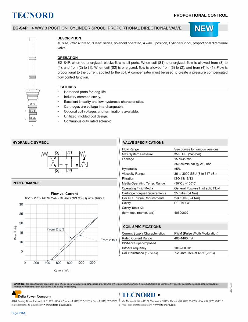
Via Malavolti, 36 • 41122 Modena • ITALY • Phone +39 (059) 254895 • Fax +39 (059) 253512 mail: [email protected] • www.tecnord.com
4484 Boeing Drive Rockford, IL 61109 • USA • Phone +1 (815) 397-6628 • Fax +1 (815) 397-2526 mail: [email protected] • www.delta-power.com
WARNING: the specifications/application data shown in our catalogs and data sheets are intended only as a general guide for the product described (herein). Any specific application should not be undertaken without independent study, evaluation, and testing for suitability.
Page PT54
PROPORTIONAL CONTROLW
9 / 2016
DESCRIPTION10 size, 7/8-14 thread, “Delta” series, solenoid operated, 4 way 3 position, Cylinder Spool, proportional directional valve.
OPERATIONEG-S4P, when de-energized, blocks flow to all ports. When coil (S1) is energized, flow is allowed from (3) to (4), and from (2) to (1). When coil (S2) is energized, flow is allowed from (3) to (2), and from (4) to (1). Flow is proportional to the current applied to the coil. A compensator must be used to create a pressure compensated flow control function.
FEATURES • Hardened parts for long-life.• Industry common cavity.• Excellent linearity and low hysteresis characteristics.• Cartridges are voltage interchangeable.• Optional coil voltages and terminations available.• Unitized, molded coil design.• Continuous duty rated solenoid.
Flow Range See curves for various versionsMax System Pressure 3500 PSI (245 bar)Leakage 15 cu-in/min 250 cc/min bar @ 210 barHysteresis ±5%Viscosity Range 36 to 3000 SSU (3 to 647 cSt)Filtration ISO 18/16/13Media Operating Temp. Range -30°C / +100°COperating Fluid Media General Purpose Hydraulic FluidCartridge Torque Requirements 25 ft-lbs (34 Nm)Coil Nut Torque Requirements 2-3 ft-lbs (3-4 Nm)Cavity DELTA 4WCavity Tools Kit(form tool, reamer, tap) 40500002
Current Supply Characteristics PWM (Pulse Width Modulation)Rated Current Range 400-1400 mAPWM or Super-Imposed Dither Frequency 100-200 HzCoil Resistance (12 VDC) 7.2 Ohm ±5% at 68°F (20°C)
Pressure Compensation from inlet to work port
�������������������������
���������������
0 200 600
10
5
15
800
Current (mA)
Flow vs. Current
20
25
Flow
(l/m
in)
30
1200
From 2 to 3
1000600400
From 2 to 1EG-S4P 4 WAY 3 POSITION, CYLINDER SPOOL, PROPORTIONAL DIRECTIONAL VALVE
COIL SPECIFICATIONS
VALVE SPECIFICATIONSHYDRAULIC SYMBOL
PERFORMANCE
Flow vs. CurrentCoil 12 VDC - 130 Hz PWM - Oil 26 cSt (121 SSU) @ 50°C (104°F)
Pressure Compensation from inlet to work port
�������������������������
���������������
0 200 600
10
5
15
800
Current (mA)
Flow vs. Current
20
25
Flow
(l/m
in)
30
1200
From 2 to 3
1000600400
From 2 to 1Flow
(l/m
in)
Current (mA)
(3) (1)
(2) (4)
NEW

Via Malavolti, 36 • 41122 Modena • ITALY • Phone +39 (059) 254895 • Fax +39 (059) 253512 mail: [email protected] • www.tecnord.com
4484 Boeing Drive Rockford, IL 61109 • USA • Phone +1 (815) 397-6628 • Fax +1 (815) 397-2526 mail: [email protected] • www.delta-power.com
WARNING: the specifications/application data shown in our catalogs and data sheets are intended only as a general guide for the product described (herein). Any specific application should not be undertaken without independent study, evaluation, and testing for suitability.
Page PT55
PROPORTIONAL CONTROLW
9 /
201
6
S4P
S4M
Pressure Drop vs. Flow
S2
S1
Pressure Compensation from inlet to work port
�������������������������
���������������
0 200 600
10
5
15
800
Current (mA)
Flow vs. Current
20
25
Flow
(l/m
in)
30
1200
From 2 to 3
1000600400
From 2 to 1
S4P
S4M
Pressure Drop vs. Flow
S2
S1
DIMENSIONS
(for bodies style and sizes see section “Accessories”)
ORDERING INFORMATION
NOTES: for other seals, consult factory.
Approximate Coil Weight: .47 lbs (.21 kg)
EG-S4P – – – –
OPTIONS BODIESBuna Standard B0 Up to 22 l/min Blank Without Body
N 3/8” BSP PortsS #6 SAE Ports
VOLTAGE12 12 VDC24 24 VDC
“L” COIL TERMINATIONHC DIN 43650 (Hirschmann)DT Deutsch-Integral DT04-2P
Pressure Drop vs. Flow Coil 12 VDC - 130 Hz PWM - Oil 26 cSt (121 SSU) @ 50°C (104°F)
Pressure Compensation from Inlet to Work Port Coil 12 VDC - 130 Hz PWM - Oil 26 cSt (121 SSU) @ 50°C (104°F)
Reg
ulat
ed F
low
(l/m
in)
Differential Pressure (bar)
Flow (l/min)
Pre
ssur
e D
rop
(bar
)

MOTORIZED CARTRIDGESW
9 /
201
6
Page DC1
Via Malavolti, 36 • 41122 Modena • ITALY • Phone +39 (059) 254895 • Fax +39 (059) 253512 mail: [email protected] • www.tecnord.com
4484 Boeing Drive Rockford, IL 61109 • USA • Phone +1 (815) 397-6628 • Fax +1 (815) 397-2526 mail: [email protected] • www.delta-power.com
WARNING: the specifications/application data shown in our catalogs and data sheets are intended only as a general guide for the product described (herein). Any specific application should not be undertaken without independent study, evaluation, and testing for suitability.
MOTORIZED NEEDLE FLOW CONTROL VALVE ................................................................................................. DC4
MOTORIZED ADJUSTABLE PRESSURE COMPENSATED FLOW CONTROL VALVE ..................................... DC8
MOTORIZED ADJUSTABLE PRIORITY FLOW CONTROL VALVE ..................................................................... DC10
MOTORIZED PILOT OPERATED RELIEF VALVE .............................................................................................. DC14
MOTORIZED PRESSURE REDUCING, RELIEVING VALVE ............................................................................... DC16
ELECTRICAL CONNECTIONS ............................................................................................................................ DC18
Section / Description page
MOTORIZED CARTRIDGES

MOTORIZED CARTRIDGES
Page DC2
W 9 / 2016
Via Malavolti, 36 • 41122 Modena • ITALY • Phone +39 (059) 254895 • Fax +39 (059) 253512 mail: [email protected] • www.tecnord.com
4484 Boeing Drive Rockford, IL 61109 • USA • Phone +1 (815) 397-6628 • Fax +1 (815) 397-2526 mail: [email protected] • www.delta-power.com
WARNING: the specifications/application data shown in our catalogs and data sheets are intended only as a general guide for the product described (herein). Any specific application should not be undertaken without independent study, evaluation, and testing for suitability.

MOTORIZED CARTRIDGESW
9 /
201
6
Page DC3
Via Malavolti, 36 • 41122 Modena • ITALY • Phone +39 (059) 254895 • Fax +39 (059) 253512 mail: [email protected] • www.tecnord.com
4484 Boeing Drive Rockford, IL 61109 • USA • Phone +1 (815) 397-6628 • Fax +1 (815) 397-2526 mail: [email protected] • www.delta-power.com
WARNING: the specifications/application data shown in our catalogs and data sheets are intended only as a general guide for the product described (herein). Any specific application should not be undertaken without independent study, evaluation, and testing for suitability.
FLOW RESTRICTORS (NEEDLE VALVES) GPM PSI LPM BAR CAVITY MODEL PAGE
12 3500 45 245 7/8-14 AE-NVA DC4
40 3500 150 245 1 5/16-12 AJ-NVA DC6
MOTORIZED FLOW REGULATORS
2W PRES. COMPENSATED FLOW REGULATORS GPM PSI LPM BAR CAVITY MODEL PAGE
24 3500 90 245 1 5/16-12 AJ-FCA DC8
3W PRES. COMPENSATED FLOW REGULATORS GPM PSI LPM BAR CAVITY MODEL PAGE
24 3500 90 245 1 5/16-12 AK-FCQ DC10
Motorized flow control valves are useful in controlling flow to an actuator in applications which do not require frequent flow adjustment. Since they only require power when a flow setting change is required, they can provide an advantage over proportional flow controls which require continuous power to the coil to maintain flow. In the example below, two AE-NVA’s are used to provide independent, pressure compensated flow control to their respective hydraulic motors, while excess pump flow is bypassed to tank across a pressure compensating element, such as a TR-PCA-0P. In this circuit, maximum attainable flow rate across the AE-NVA is dependent upon the pressure setting of the compensator.The Super series AJ-FCA provides pressure compensated, restrictive flow control up to 25gpm.The AK-FCQ provides pressure compensated, priority flow control up to 25gpm.
TYPICAL SCHEMATIC
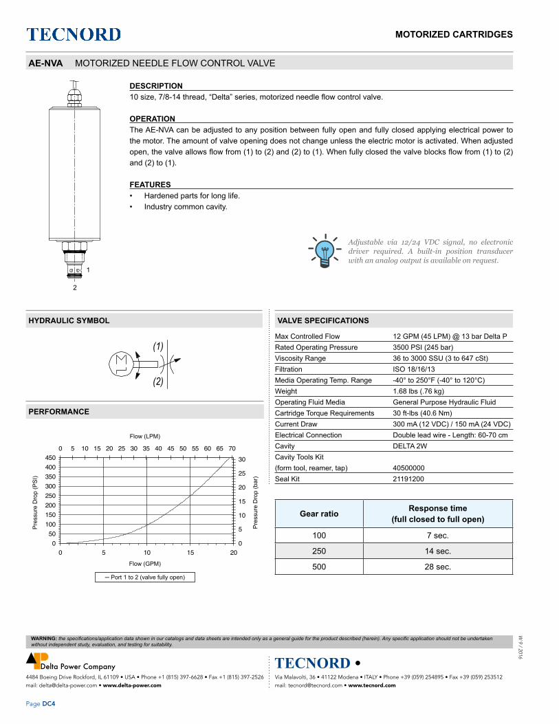
MOTORIZED CARTRIDGES
Page DC4
W 9 / 2016
Via Malavolti, 36 • 41122 Modena • ITALY • Phone +39 (059) 254895 • Fax +39 (059) 253512 mail: [email protected] • www.tecnord.com
4484 Boeing Drive Rockford, IL 61109 • USA • Phone +1 (815) 397-6628 • Fax +1 (815) 397-2526 mail: [email protected] • www.delta-power.com
WARNING: the specifications/application data shown in our catalogs and data sheets are intended only as a general guide for the product described (herein). Any specific application should not be undertaken without independent study, evaluation, and testing for suitability.
DESCRIPTION10 size, 7/8-14 thread, “Delta” series, motorized needle flow control valve.
OPERATIONThe AE-NVA can be adjusted to any position between fully open and fully closed applying electrical power to the motor. The amount of valve opening does not change unless the electric motor is activated. When adjusted open, the valve allows flow from (1) to (2) and (2) to (1). When fully closed the valve blocks flow from (1) to (2) and (2) to (1).
FEATURES • Hardened parts for long life.• Industry common cavity.
Max Controlled Flow 12 GPM (45 LPM) @ 13 bar Delta PRated Operating Pressure 3500 PSI (245 bar)Viscosity Range 36 to 3000 SSU (3 to 647 cSt)Filtration ISO 18/16/13Media Operating Temp. Range -40° to 250°F (-40° to 120°C)Weight 1.68 lbs (.76 kg)Operating Fluid Media General Purpose Hydraulic FluidCartridge Torque Requirements 30 ft-lbs (40.6 Nm) Current Draw 300 mA (12 VDC) / 150 mA (24 VDC)Electrical Connection Double lead wire - Length: 60-70 cmCavity DELTA 2WCavity Tools Kit(form tool, reamer, tap) 40500000Seal Kit 21191200
050
100150200250300350400450
0 5 10 15 20Flow (GPM)
Pres
sure
Dro
p (P
SI)
0
5
10
15
20
25
300 5 10 15 20 25 30 35 40 45 50 55 60 65 70
Flow (LPM)
Pres
sure
Dro
p (B
AR)
Port 1 to 2 (valve fully open)
2
1
1
2
M
050
100150200250300350400450
0 5 10 15 20Flow (GPM)
Pres
sure
Dro
p (P
SI)
0
5
10
15
20
25
300 5 10 15 20 25 30 35 40 45 50 55 60 65 70
Flow (LPM)
Pres
sure
Dro
p (B
AR)
Port 1 to 2 (valve fully open)
2
1
1
2
M
Gear ratio Response time(full closed to full open)
100 7 sec.
250 14 sec.
500 28 sec.
AE-NVA MOTORIZED NEEDLE FLOW CONTROL VALVE
VALVE SPECIFICATIONS
Adjustable via 12/24 VDC signal, no electronic driver required. A built-in position transducer with an analog output is available on request.
HYDRAULIC SYMBOL
PERFORMANCE
Pre
ssur
e D
rop
(PS
I)
Pre
ssur
e D
rop
(bar
)
Flow (LPM)
─ Port 1 to 2 (valve fully open)
Flow (GPM)

MOTORIZED CARTRIDGESW
9 /
201
6
Page DC5
Via Malavolti, 36 • 41122 Modena • ITALY • Phone +39 (059) 254895 • Fax +39 (059) 253512 mail: [email protected] • www.tecnord.com
4484 Boeing Drive Rockford, IL 61109 • USA • Phone +1 (815) 397-6628 • Fax +1 (815) 397-2526 mail: [email protected] • www.delta-power.com
WARNING: the specifications/application data shown in our catalogs and data sheets are intended only as a general guide for the product described (herein). Any specific application should not be undertaken without independent study, evaluation, and testing for suitability.
AE-NVA – – – –
OPTIONS BODIESBuna Standard 00 Blank Without Body
N 3/8” BSP PortsS #6 SAE Ports
GEAR RATIO R500R250 VOLTAGER100 24 24 VDC
12 12 VDC
DIMENSIONS
ORDERING INFORMATION
(for bodies style and sizes see section “Accessories”)

MOTORIZED CARTRIDGES
Page DC6
W 9 / 2016
Via Malavolti, 36 • 41122 Modena • ITALY • Phone +39 (059) 254895 • Fax +39 (059) 253512 mail: [email protected] • www.tecnord.com
4484 Boeing Drive Rockford, IL 61109 • USA • Phone +1 (815) 397-6628 • Fax +1 (815) 397-2526 mail: [email protected] • www.delta-power.com
WARNING: the specifications/application data shown in our catalogs and data sheets are intended only as a general guide for the product described (herein). Any specific application should not be undertaken without independent study, evaluation, and testing for suitability.
DESCRIPTION16 size, 1 5/16-12 thread, “Super” series, motorized needle flow control valve.
OPERATIONThe AJ-NVA can be adjusted to any position between fully open and fully closed by applying electrical power to the motor. The amount of valve opening does not change unless the electric motor is activated. When adjusted open, the valve allows flow from (1) to (2) and (2) to (1). When fully closed the valve blocks flow from (1) to (2) and (2) to (1).
FEATURES • Hardened parts for long life.• Industry common cavity.
Max Controlled Flow 40 GPM (150 LPM) @ 15 bar Delta PMax Operating Pressure 3500 PSI (245 bar)Viscosity Range 36 to 3000 SSU (3 to 647 cSt)Filtration ISO 18/16/13Media Operating Temp. Range -40° to 250°F (-40° to 120°C)Weight 2.24 lbs (1.02 kg)Operating Fluid Media General Purpose Hydraulic FluidCartridge Torque Requirements 90 ft-lbs (122 Nm)Current Draw 300 mA (12 VDC) / 150 mA (24 VDC)Electrical Connection Double lead wire - Length: 50-60 cmCavity SUPER 2WCavity Tools Kit(form tool, reamer, tap) 40500017Seal Kit 21191401
1
2
M
Gear ratio Response time(full closed to full open)
100 12 sec.
250 28 sec.
500 55 sec.
AJ-NVA MOTORIZED NEEDLE FLOW CONTROL VALVE
VALVE SPECIFICATIONS
Adjustable via 12/24 VDC signal, no electronic driver required. A built-in position transducer with an analog output is available on request.
HYDRAULIC SYMBOL
PERFORMANCE
1
2
M
∆P (bar)
Flow (lt/min)

MOTORIZED CARTRIDGESW
9 /
201
6
Page DC7
Via Malavolti, 36 • 41122 Modena • ITALY • Phone +39 (059) 254895 • Fax +39 (059) 253512 mail: [email protected] • www.tecnord.com
4484 Boeing Drive Rockford, IL 61109 • USA • Phone +1 (815) 397-6628 • Fax +1 (815) 397-2526 mail: [email protected] • www.delta-power.com
WARNING: the specifications/application data shown in our catalogs and data sheets are intended only as a general guide for the product described (herein). Any specific application should not be undertaken without independent study, evaluation, and testing for suitability.
AJ-NVA – – – –
OPTIONS BODIESBuna Standard 00 Blank Without Body
N 3/4” BSP PortsS #12 SAE Ports
GEAR RATIO R500R250 VOLTAGER100 24 24 VDC
12 12 VDC
DIMENSIONS
ORDERING INFORMATION
(for bodies style and sizes see section “Accessories”)

MOTORIZED CARTRIDGES
Page DC8
W 9 / 2016
Via Malavolti, 36 • 41122 Modena • ITALY • Phone +39 (059) 254895 • Fax +39 (059) 253512 mail: [email protected] • www.tecnord.com
4484 Boeing Drive Rockford, IL 61109 • USA • Phone +1 (815) 397-6628 • Fax +1 (815) 397-2526 mail: [email protected] • www.delta-power.com
WARNING: the specifications/application data shown in our catalogs and data sheets are intended only as a general guide for the product described (herein). Any specific application should not be undertaken without independent study, evaluation, and testing for suitability.
DESCRIPTION16 size, 1 5/16-12 thread, “Super” series, motorized adjustable pressure compensated flow control valve.
OPERATIONThe AJ-FCA maintains a constant flow rate out of (1) regardless of load pressure changes in the circuit downstream of (1). The valve begins to respond to load changes when the flow through the valve creates a pressure differential across the control orifice greater than 100 PSI (6.9 bar), with accurate flow maintenance from 100 to 3500 PSI (6.9 to 240 bar).Reverse flow (1) to (2) returns through the control orifice and is non-compensated.
FEATURES • Hardened parts for long life.• Industry common cavity.• Fine low-torque adjustment.
Max Controlled Flow 24 GPM (90 LPM)Max Operating Pressure 3500 PSI (245 bar)Viscosity Range 36 to 3000 SSU (3 to 647 cSt)Filtration ISO 18/16/13Media Operating Temp. Range -40° to 250°F (-40° to 120°C)Weight 2.24 lbs (1.02 kg)Operating Fluid Media General Purpose Hydraulic FluidCartridge Torque Requirements 90 ft-lbs (122 Nm)Current Draw 300 mA (12 VDC) / 150 mA (24 VDC)Electrical Connection Double lead wire - Length: 50-60 cmCavity SUPER 2WCavity Tools Kit(form tool, reamer, tap) 40500017Seal Kit 21191400
1
2
M
2
1
1
2
M
2
1
Gear ratio options(see ordering code)
Response time(full closed to full open)
100 9 sec.
250 22 sec.
500 45 sec.
AJ-FCA MOTORIZED ADJUSTABLE PRESSURE COMPENSATED FLOW CONTROL VALVE
HYDRAULIC SYMBOL
PERFORMANCE
VALVE SPECIFICATIONS
Adjustable via 12/24 VDC signal, no electronic driver required. A built-in position transducer with an analog output is available on request.
Q (lt/min)
P (bar)

MOTORIZED CARTRIDGESW
9 /
201
6
Page DC9
Via Malavolti, 36 • 41122 Modena • ITALY • Phone +39 (059) 254895 • Fax +39 (059) 253512 mail: [email protected] • www.tecnord.com
4484 Boeing Drive Rockford, IL 61109 • USA • Phone +1 (815) 397-6628 • Fax +1 (815) 397-2526 mail: [email protected] • www.delta-power.com
WARNING: the specifications/application data shown in our catalogs and data sheets are intended only as a general guide for the product described (herein). Any specific application should not be undertaken without independent study, evaluation, and testing for suitability.
AJ-FCA – – – –
OPTIONS BODIESBuna Standard 00 Blank Without Body
N 3/4” BSP PortsS #12 SAE Ports
GEAR RATIO R500R250 VOLTAGER100 24 24 VDC
12 12 VDC
DIMENSIONS
ORDERING INFORMATION
(for bodies style and sizes see section “Accessories”)

MOTORIZED CARTRIDGES
Page DC10
W 9 / 2016
Via Malavolti, 36 • 41122 Modena • ITALY • Phone +39 (059) 254895 • Fax +39 (059) 253512 mail: [email protected] • www.tecnord.com
4484 Boeing Drive Rockford, IL 61109 • USA • Phone +1 (815) 397-6628 • Fax +1 (815) 397-2526 mail: [email protected] • www.delta-power.com
WARNING: the specifications/application data shown in our catalogs and data sheets are intended only as a general guide for the product described (herein). Any specific application should not be undertaken without independent study, evaluation, and testing for suitability.
DESCRIPTION16 size, 1 5/16-12 thread, “Super” series, motorized adjustable priority flow control valve.
OPERATIONThe AK-FCQ allows pressure compensated flow from (3) to (1) regulated the pressure present at (3). Excess flow passes out (2). The spring chamber is constantly vented at (1).
FEATURES • Hardened parts for long life.• Industry common cavity.
Max Regulated Flow 24 GPM (90 LPM)Rated Operating Pressure 3500 PSI (245 bar)Viscosity Range 36 to 3000 SSU (3 to 647 cSt)Filtration ISO 18/16/13Media Operating Temp. Range -40° to 250°F (-40° to 120°C)Weight 2.34 lbs (1.06 kg)Operating Fluid Media General Purpose Hydraulic FluidCartridge Torque Requirements 90 ft-lbs (122 Nm)Current Draw 300 mA (12 VDC) / 150 mA (24 VDC)Electrical Connection Double lead wire - Length: 50-60 cmCavity SUPER 3WCavity Tools Kit(form tool, reamer, tap) 40500018Seal Kit 21191404
1
3
2 M
3
2
1
0
5
10
15
20
0 500 1000 1500 2000 2500 3000
Pressure @ Port 1 (PSI)
Reg
ulat
ed F
low
(GP
M)
0
25
50
750 50 100 150 200
Pressure @ Port 1 (BAR)
Reg
ulat
ed F
low
(LP
M)
priority port 1 loaded, bypass port 2 unloaded
0
5
10
15
20
0 500 1000 1500 2000 2500 3000Pressure @ Port 2 (PSI)
Reg
ulat
ed F
low
(GP
M)
0
25
50
750 50 100 150 200
Pressure @ Port 2 (BAR)
Reg
ulat
ed F
low
(LP
M)
bypass port 2 loaded, priority port 1 unloaded
1
3
2 M
3
2
1
0
5
10
15
20
0 500 1000 1500 2000 2500 3000
Pressure @ Port 1 (PSI)
Reg
ulat
ed F
low
(GP
M)
0
25
50
750 50 100 150 200
Pressure @ Port 1 (BAR)
Reg
ulat
ed F
low
(LP
M)
priority port 1 loaded, bypass port 2 unloaded
0
5
10
15
20
0 500 1000 1500 2000 2500 3000Pressure @ Port 2 (PSI)
Reg
ulat
ed F
low
(GP
M)
0
25
50
750 50 100 150 200
Pressure @ Port 2 (BAR)
Reg
ulat
ed F
low
(LP
M)
bypass port 2 loaded, priority port 1 unloaded
AK-FCQ MOTORIZED ADJUSTABLE PRIORITY FLOW CONTROL VALVE
VALVE SPECIFICATIONS
PERFORMANCE
HYDRAULIC SYMBOL
Adjustable via 12/24 VDC signal, no electronic driver required. A built-in position transducer with an analog output is available on request.
Reg
ulat
ed F
low
(GP
M)
Reg
ulat
ed F
low
(LP
M)
Reg
ulat
ed F
low
(GP
M)
Reg
ulat
ed F
low
(LP
M)
Pressure @ Port 2 (bar) Pressure @ Port 1 (bar)
─ bypass port 2 loaded, priority port 1 unloaded ─ priority port 1 loaded, bypass port 2 unloaded
Pressure @ Port 2 (PSI) Pressure @ Port 1 (PSI)

MOTORIZED CARTRIDGESW
9 /
201
6
Page DC11
Via Malavolti, 36 • 41122 Modena • ITALY • Phone +39 (059) 254895 • Fax +39 (059) 253512 mail: [email protected] • www.tecnord.com
4484 Boeing Drive Rockford, IL 61109 • USA • Phone +1 (815) 397-6628 • Fax +1 (815) 397-2526 mail: [email protected] • www.delta-power.com
WARNING: the specifications/application data shown in our catalogs and data sheets are intended only as a general guide for the product described (herein). Any specific application should not be undertaken without independent study, evaluation, and testing for suitability.
Gear ratio options(see ordering code)
Response time(full closed to full open)
100 9 sec.
250 22 sec.
500 45 sec.
AK-FCQ – – – –
OPTIONS BODIESBuna Standard 00 Blank Without Body
N 3/4” BSP PortsS #12 SAE Ports
GEAR RATIO R500R250 VOLTAGER100 24 24 VDC
12 12 VDC
DIMENSIONS
ORDERING INFORMATION
(for bodies style and sizes see section “Accessories”)

MOTORIZED CARTRIDGES
Page DC12
W 9 / 2016
Via Malavolti, 36 • 41122 Modena • ITALY • Phone +39 (059) 254895 • Fax +39 (059) 253512 mail: [email protected] • www.tecnord.com
4484 Boeing Drive Rockford, IL 61109 • USA • Phone +1 (815) 397-6628 • Fax +1 (815) 397-2526 mail: [email protected] • www.delta-power.com
WARNING: the specifications/application data shown in our catalogs and data sheets are intended only as a general guide for the product described (herein). Any specific application should not be undertaken without independent study, evaluation, and testing for suitability.

MOTORIZED CARTRIDGESW
9 /
201
6
Page DC13
Via Malavolti, 36 • 41122 Modena • ITALY • Phone +39 (059) 254895 • Fax +39 (059) 253512 mail: [email protected] • www.tecnord.com
4484 Boeing Drive Rockford, IL 61109 • USA • Phone +1 (815) 397-6628 • Fax +1 (815) 397-2526 mail: [email protected] • www.delta-power.com
WARNING: the specifications/application data shown in our catalogs and data sheets are intended only as a general guide for the product described (herein). Any specific application should not be undertaken without independent study, evaluation, and testing for suitability.
MOTORIZED PRESSURE CONTROLS
RELIEF VALVES GPM PSI LPM BAR CAVITY MODEL PAGE
37 3500 140 245 1 5/16-12 AJ-RVR DC14
PRESSURE REDUCING VALVES GPM PSI LPM BAR CAVITY MODEL PAGE
10 3000 38 207 7/8-14 AF-PRP DC16

MOTORIZED CARTRIDGES
Page DC14
W 9 / 2016
Via Malavolti, 36 • 41122 Modena • ITALY • Phone +39 (059) 254895 • Fax +39 (059) 253512 mail: [email protected] • www.tecnord.com
4484 Boeing Drive Rockford, IL 61109 • USA • Phone +1 (815) 397-6628 • Fax +1 (815) 397-2526 mail: [email protected] • www.delta-power.com
WARNING: the specifications/application data shown in our catalogs and data sheets are intended only as a general guide for the product described (herein). Any specific application should not be undertaken without independent study, evaluation, and testing for suitability.
DESCRIPTION16 size, 1 5/16-12 thread, “Super” series, motorized adjustable pilot-operated pressure relief valve.
OPERATIONThe AJ-RVR blocks flow from (2) to (1) until sufficient pressure is present at (2). The setting of the AJ-RVR can be adjusted to any value between 14 and 245 bar (200-3500 PSI) applying electrical power to the motor. The setting does not change unless the electrical motor is activated. Reverse flow (1) to (2) occurs when the pressure at (1) is at least 2.1 bar (30 PSI) higher then at port (2).
FEATURES • Hardened parts for long life.• Industry common cavity.• Fine low-torque adjustment.
Max Controlled Flow 37 GPM (140 LPM) Max Operating Pressure 3500 PSI (245 bar) Viscosity Range 36 to 3000 SSU (3 to 647 cSt) Filtration ISO 18/16/13Media Operating Temp. Range -40° to 250°F (-40° to 120°C) Weight 2.24 lbs (1.02 kg) Operating Fluid Media General Purpose Hydraulic FluidCartridge Torque Requirements 90 ft-lbs (122 Nm) Current Draw 300 mA (12 VDC) / 150 mA (24 VDC) Electrical Connection Double lead wire - Length: 50-60 cmCavity SUPER 2WCavity Tools Kit(form tool, reamer, tap) 40500017 Seal Kit 21191400
2 1
M2 1
M
Gear ratio options(see ordering code)
Response time(full closed to full open)
250 12 sec.
500 27 sec.
AJ-RVR MOTORIZED PILOT OPERATED RELIEF VALVE
VALVE SPECIFICATIONS
Adjustable via 12/24 VDC signal, no electronic driver required. A built-in position transducer with an analog output is available on request.
HYDRAULIC SYMBOL
PERFORMANCE
Pressure (bar)
Flow (lt/min)
Reverse Flow

MOTORIZED CARTRIDGESW
9 /
201
6
Page DC15
Via Malavolti, 36 • 41122 Modena • ITALY • Phone +39 (059) 254895 • Fax +39 (059) 253512 mail: [email protected] • www.tecnord.com
4484 Boeing Drive Rockford, IL 61109 • USA • Phone +1 (815) 397-6628 • Fax +1 (815) 397-2526 mail: [email protected] • www.delta-power.com
WARNING: the specifications/application data shown in our catalogs and data sheets are intended only as a general guide for the product described (herein). Any specific application should not be undertaken without independent study, evaluation, and testing for suitability.
WARNING: The specifi cations/application data shown in our catalogs and data sheets are intended only as a general guide for the product described (herein). Any specifi c application should not be undertaken without independent study, evaluation, and testing for suitability.
Phone +39 059 254895 • Fax +39 059 253512 • E-mail: [email protected]
MOTORIZED FLOW REGULATORS - page 13
AJ-RVR – – – –
OPTIONS BODIESBuna Standard 00 Blank Without Body
N 3/4” BSP PortsS #12 SAE Ports
GEAR RATIO R250R100 VOLTAGE
24 24 VDC12 12 VDC
DIMENSIONS
ORDERING INFORMATION
(for bodies style and sizes see section “Accessories”)

MOTORIZED CARTRIDGES
Page DC16
W 9 / 2016
Via Malavolti, 36 • 41122 Modena • ITALY • Phone +39 (059) 254895 • Fax +39 (059) 253512 mail: [email protected] • www.tecnord.com
4484 Boeing Drive Rockford, IL 61109 • USA • Phone +1 (815) 397-6628 • Fax +1 (815) 397-2526 mail: [email protected] • www.delta-power.com
WARNING: the specifications/application data shown in our catalogs and data sheets are intended only as a general guide for the product described (herein). Any specific application should not be undertaken without independent study, evaluation, and testing for suitability.
3
21
3
2
1
DESCRIPTION10 size, 7/8-14 thread, “Delta” series, motorized adjustable pressure reducing, relieving valve, pilot opearated.
OPERATIONThe AF-PRP can be adjusted to any position between fully open and fully closed applying electrical power to the motor. When a pre-determined pressure is reached at (3), the spool shifts to restrict input flow at (2), thereby reducing (restricting) flow. If valve and pressure at port (3) exceeds setting, spool shift to open passage at port (1), thereby regulating pressure at port (3) by relieving excess flow.
FEATURES • Hardened parts for long life.• Industry common cavity.
Nominal Flow 10 GPM (38 LPM)Rated Operating Pressure 4000 PSI (276 bar)Viscosity Range 36 to 3000 SSU (3 to 647 cSt)Filtration ISO 18/16/13Media Operating Temp. Range -40° to 250°F (-40° to 120°C)Weight .59 lbs (.27 kg)Operating Fluid Media General Purpose Hydraulic FluidCartridge Torque Requirements 30 ft-lbs (40.6 Nm)Cavity DELTA 3WCavity Tools Kit(form tool, reamer, tap) 40500001Seal Kit 21191206
AF-PRP MOTORIZED PRESSURE REDUCING, RELIEVING VALVE
VALVE SPECIFICATIONS
PERFORMANCE
HYDRAULIC SYMBOL
3
21
3
2
1
3
21
3
2
1
Reg
ulat
ed P
ress
ure
(PS
I)
Reg
ulat
ed P
ress
ure
(bar
)
Pre
ssur
e D
rop
(PS
I)
Pre
ssur
e D
rop
(bar
)
Flow (LPM) Flow (LPM)
Flow (GPM) Flow (GPM)

MOTORIZED CARTRIDGESW
9 /
201
6
Page DC17
Via Malavolti, 36 • 41122 Modena • ITALY • Phone +39 (059) 254895 • Fax +39 (059) 253512 mail: [email protected] • www.tecnord.com
4484 Boeing Drive Rockford, IL 61109 • USA • Phone +1 (815) 397-6628 • Fax +1 (815) 397-2526 mail: [email protected] • www.delta-power.com
WARNING: the specifications/application data shown in our catalogs and data sheets are intended only as a general guide for the product described (herein). Any specific application should not be undertaken without independent study, evaluation, and testing for suitability.
(for bodies style and sizes see section “Accessories”)
Gear ratio Response time(full closed to full open)
100 7 sec.
250 14 sec.
500 28 sec.
AF-PRP – – – –
OPTIONS BODIESBuna Standard 00 Blank Without Body
N 3/8” BSP PortsS #6 SAE Ports
GEAR RATIO R500R250 VOLTAGER100 24 24 VDC
12 12 VDC
DIMENSIONS
ORDERING INFORMATION
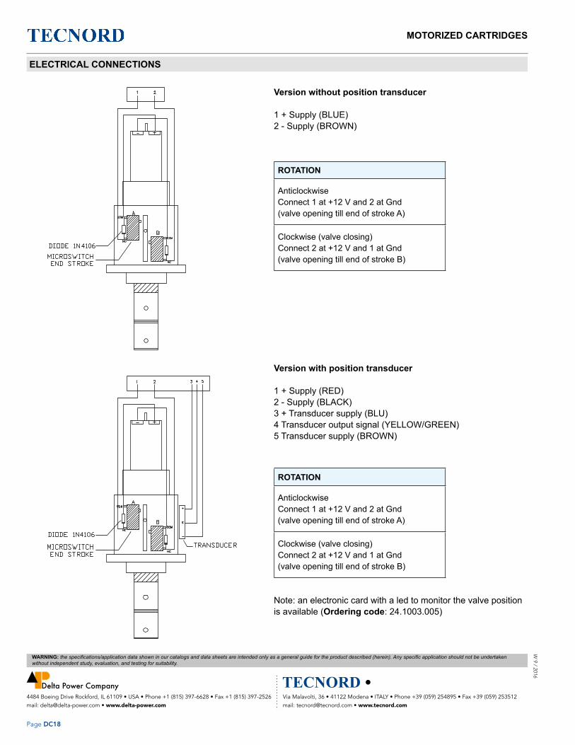
MOTORIZED CARTRIDGES
Page DC18
W 9 / 2016
Via Malavolti, 36 • 41122 Modena • ITALY • Phone +39 (059) 254895 • Fax +39 (059) 253512 mail: [email protected] • www.tecnord.com
4484 Boeing Drive Rockford, IL 61109 • USA • Phone +1 (815) 397-6628 • Fax +1 (815) 397-2526 mail: [email protected] • www.delta-power.com
WARNING: the specifications/application data shown in our catalogs and data sheets are intended only as a general guide for the product described (herein). Any specific application should not be undertaken without independent study, evaluation, and testing for suitability.
ELECTRICAL CONNECTIONS
Version without position transducer
1 + Supply (BLUE)2 - Supply (BROWN)
ROTATION
AnticlockwiseConnect 1 at +12 V and 2 at Gnd (valve opening till end of stroke A)
Clockwise (valve closing)Connect 2 at +12 V and 1 at Gnd (valve opening till end of stroke B)
Version with position transducer
1 + Supply (RED)2 - Supply (BLACK)3 + Transducer supply (BLU)4 Transducer output signal (YELLOW/GREEN)5 Transducer supply (BROWN)
ROTATION
AnticlockwiseConnect 1 at +12 V and 2 at Gnd (valve opening till end of stroke A)
Clockwise (valve closing)Connect 2 at +12 V and 1 at Gnd (valve opening till end of stroke B)
Note: an electronic card with a led to monitor the valve position is available (Ordering code: 24.1003.005)

MECHANICAL PRESSURE COMPENSATORSW
9 /
201
6
Page MC1
Via Malavolti, 36 • 41122 Modena • ITALY • Phone +39 (059) 254895 • Fax +39 (059) 253512 mail: [email protected] • www.tecnord.com
4484 Boeing Drive Rockford, IL 61109 • USA • Phone +1 (815) 397-6628 • Fax +1 (815) 397-2526 mail: [email protected] • www.delta-power.com
WARNING: the specifications/application data shown in our catalogs and data sheets are intended only as a general guide for the product described (herein). Any specific application should not be undertaken without independent study, evaluation, and testing for suitability.
2 WAY COMPENSATING/REDUCING VALVES ..................................................................................................... MC3
2 WAY RESTRICTIVE TYPE COMPENSATORS .................................................................................................. MC9
2 WAY BYPASS TYPE FOR 3 WAY FLOW CONTROL ........................................................................................ MC13
4 WAY PRIORITY TYPE COMPENSATOR WITH BYPASS LINE ........................................................................ MC23
Section / Description page
MECHANICAL PRESSURE COMPENSATORS

MECHANICAL PRESSURE COMPENSATORS
Page MC2
W 9 / 2016
Via Malavolti, 36 • 41122 Modena • ITALY • Phone +39 (059) 254895 • Fax +39 (059) 253512 mail: [email protected] • www.tecnord.com
4484 Boeing Drive Rockford, IL 61109 • USA • Phone +1 (815) 397-6628 • Fax +1 (815) 397-2526 mail: [email protected] • www.delta-power.com
WARNING: the specifications/application data shown in our catalogs and data sheets are intended only as a general guide for the product described (herein). Any specific application should not be undertaken without independent study, evaluation, and testing for suitability.

MECHANICAL PRESSURE COMPENSATORSW
9 /
201
6
Page MC3
Via Malavolti, 36 • 41122 Modena • ITALY • Phone +39 (059) 254895 • Fax +39 (059) 253512 mail: [email protected] • www.tecnord.com
4484 Boeing Drive Rockford, IL 61109 • USA • Phone +1 (815) 397-6628 • Fax +1 (815) 397-2526 mail: [email protected] • www.delta-power.com
WARNING: the specifications/application data shown in our catalogs and data sheets are intended only as a general guide for the product described (herein). Any specific application should not be undertaken without independent study, evaluation, and testing for suitability.
GPM PSI LPM BAR CAVITY MODEL PAGE
8 3500 30 245 7/8-14 DF-CP2 MC4
19 3500 70 245 Special QC-CP2 MC6
2 WAY COMPENSATING/REDUCING VALVES
Typical application for the CP2 is in a proportional circuit to achieve pressure compensated flow control.The pressure compensator is located upstream of the orifice and is spring biased to an open position.
TYPICAL SCHEMATIC

W 9 / 2016
Via Malavolti, 36 • 41122 Modena • ITALY • Phone +39 (059) 254895 • Fax +39 (059) 253512 mail: [email protected] • www.tecnord.com
4484 Boeing Drive Rockford, IL 61109 • USA • Phone +1 (815) 397-6628 • Fax +1 (815) 397-2526 mail: [email protected] • www.delta-power.com
WARNING: the specifications/application data shown in our catalogs and data sheets are intended only as a general guide for the product described (herein). Any specific application should not be undertaken without independent study, evaluation, and testing for suitability.
MECHANICAL PRESSURE COMPENSATORS
Page MC4
DESCRIPTION10 size, 7/8-14 thread, “Delta” series, 2 ways pressure compensating/reducing valve.
OPERATIONThe DF-CP2 allows pressure compensated flow from (2) to (3) regulated by the pressure present at (1). Pressure differential between (3) and (1) is fixed at 8/14/18 bar (according to the pressure settings). These are minimum values, increasing with the flow because of the pressure drop through the valve (see graph).When used with (1) connected to a drain line, it works as pressure reducing valve.
FEATURES • Hardened parts for long life.• Industry common cavity.• Spring range 8 to 18 bar.
DF-CP2 PRESSURE COMPENSATING/REDUCING VALVE
Nominal Flow 8 GPM (30 LPM) Rated Operating Pressure 3500 PSI (245 bar) Typical Internal Leakage (150 SSU) 35 ml/min @ 250 barViscosity Range 36 to 3000 SSU (3 to 647 cSt)Filtration ISO 18/16/13Media Operating Temp. Range -25° to +95°CWeight .35 lbs (.16 kg)Operating Fluid Media General Purpose Hydraulic FluidCartridge Torque Requirements 33 ft-lbs (45 Nm)Cavity DELTA 3WCavity Tools Kit(form tool, reamer, tap) 40500001Seal Kit 210902025
VALVE SPECIFICATIONS
Pressure compensator for 2 way flow control, typically used with an external orifice inline with port (3). Port (1) should sense upstream pressure of orifice.
HYDRAULIC SYMBOL
PERFORMANCE
Actual Test Data (Cartridge Only)
Pressure Drop (bar) vs. Flow (lt/min)For various pressure compensator settings (bar)
Pre
ssur
e dr
op (b
ar)
Flow @ Port 3 (lt/min)Inlet pressure (bar)
Flow
(lt/m
in)
Con
trol o
rifice
Dia
(mm
)DF-CP2 008 - Flow (lt/min) vs. inlet pressure (bar)
For various orifice diameters (mm)

W 9
/ 2
016
Via Malavolti, 36 • 41122 Modena • ITALY • Phone +39 (059) 254895 • Fax +39 (059) 253512 mail: [email protected] • www.tecnord.com
4484 Boeing Drive Rockford, IL 61109 • USA • Phone +1 (815) 397-6628 • Fax +1 (815) 397-2526 mail: [email protected] • www.delta-power.com
WARNING: the specifications/application data shown in our catalogs and data sheets are intended only as a general guide for the product described (herein). Any specific application should not be undertaken without independent study, evaluation, and testing for suitability.
MECHANICAL PRESSURE COMPENSATORS
Page MC5
DF-CP2 – – –
OPTIONS BODIESBuna Standard 00 Blank Without BodyViton Standard V0 N 3/8” BSP Ports
S #6 SAE Ports
PRESSURE SETTINGS008 8 bar (115 PSI)014 14 bar (200 PSI)018 18 bar (260 PSI)
Differential Pressure AcrossExternal Controlling Orifice
DIMENSIONS
ORDERING INFORMATION
(for bodies style and sizes see section “Accessories”)
Inlet pressure (bar)
Inlet pressure (bar)
Flow
(lt/m
in)
Con
trol o
rifice
Dia
(mm
)
Flow
(lt/m
in)
Con
trol o
rifice
Dia
(mm
)
DF-CP2 014 - Flow (lt/min) vs. inlet pressure (bar)For various orifice diameters (mm)
DF-CP2 018 - Flow (lt/min) vs. inlet pressure (bar)For various orifice diameters (mm)

W 9 / 2016
Via Malavolti, 36 • 41122 Modena • ITALY • Phone +39 (059) 254895 • Fax +39 (059) 253512 mail: [email protected] • www.tecnord.com
4484 Boeing Drive Rockford, IL 61109 • USA • Phone +1 (815) 397-6628 • Fax +1 (815) 397-2526 mail: [email protected] • www.delta-power.com
WARNING: the specifications/application data shown in our catalogs and data sheets are intended only as a general guide for the product described (herein). Any specific application should not be undertaken without independent study, evaluation, and testing for suitability.
MECHANICAL PRESSURE COMPENSATORS
Page MC6
DESCRIPTIONSpecial cavity, 2 ways pressure compensating/reducing valve.
OPERATIONThe QC-CP2 allows pressure compensated flow from (2) to (3) regulated by the pressure present at (1). Pressure differential between (3) and (1) is fixed at 8/14/18/24 bar (according to the pressure settings). These are minimum values, increasing with the flow because of the pressure drop through the valve (see graph). When used with (1) connected to a drain line, it works as a fix setting pressure reducing valve.
FEATURES • Hardened parts for long life.• Spring range 8 to 24 bar.
QC-CP2 PRESSURE COMPENSATING/REDUCING VALVE
Nominal Flow 19 GPM (70 LPM) Rated Operating Pressure 3500 PSI (245 bar) Typical Internal Leakage (150 SSU) 35 ml/min @ 250 barViscosity Range 36 to 3000 SSU (3 to 647 cSt)Filtration ISO 18/16/13Media Operating Temp. Range -40° to 250°F (-40° to 120°C)Weight .35 lbs (.16 kg)Operating Fluid Media General Purpose Hydraulic FluidCartridge Torque Requirements 52 ft-lbs (70 Nm)Cavity T031 (Special)Cavity Tools Kit(form tool, reamer, tap) K-T031 Seal Kit 210902012
VALVE SPECIFICATIONS
Pressure compensator for 2 way flow control, typically used with an external orifice inline with port (3). Port (1) should sense upstream pressure of orifice.
HYDRAULIC SYMBOL
PERFORMANCE
Actual Test Data (Cartridge Only)
Pressure drop (bar) vs. flow (lt/min)Flow (lt/min) vs. inlet pressure (bar)
For various press. compensator valve settings - Re: control orifice diameter: 5.5 mm
Pre
ssur
e dr
op (b
ar)
Por
t 2 to
3
Flow @ Port 3 (lt/min)Inlet pressure (bar)
Flow
(lt/m
in)

W 9
/ 2
016
Via Malavolti, 36 • 41122 Modena • ITALY • Phone +39 (059) 254895 • Fax +39 (059) 253512 mail: [email protected] • www.tecnord.com
4484 Boeing Drive Rockford, IL 61109 • USA • Phone +1 (815) 397-6628 • Fax +1 (815) 397-2526 mail: [email protected] • www.delta-power.com
WARNING: the specifications/application data shown in our catalogs and data sheets are intended only as a general guide for the product described (herein). Any specific application should not be undertaken without independent study, evaluation, and testing for suitability.
MECHANICAL PRESSURE COMPENSATORS
Page MC7
DIMENSIONS
ORDERING INFORMATION
(for bodies style and sizes see section “Accessories”)
QC-CP2 – – –
OPTIONS BODIESBuna Standard 00 Blank Without BodyViton Standard V0 N 1/2” BSP Ports
S #8 SAE Ports
PRESSURE SETTINGS008 8 bar (115 PSI)014 14 bar (200 PSI)018 18 bar (260 PSI)024 24 bar (340 PSI)
Differential Pressure AcrossExternal Controlling Orifice

MECHANICAL PRESSURE COMPENSATORS
Page MC8
W 9 / 2016
Via Malavolti, 36 • 41122 Modena • ITALY • Phone +39 (059) 254895 • Fax +39 (059) 253512 mail: [email protected] • www.tecnord.com
4484 Boeing Drive Rockford, IL 61109 • USA • Phone +1 (815) 397-6628 • Fax +1 (815) 397-2526 mail: [email protected] • www.delta-power.com
WARNING: the specifications/application data shown in our catalogs and data sheets are intended only as a general guide for the product described (herein). Any specific application should not be undertaken without independent study, evaluation, and testing for suitability.

MECHANICAL PRESSURE COMPENSATORSW
9 /
201
6
Page MC9
Via Malavolti, 36 • 41122 Modena • ITALY • Phone +39 (059) 254895 • Fax +39 (059) 253512 mail: [email protected] • www.tecnord.com
4484 Boeing Drive Rockford, IL 61109 • USA • Phone +1 (815) 397-6628 • Fax +1 (815) 397-2526 mail: [email protected] • www.delta-power.com
WARNING: the specifications/application data shown in our catalogs and data sheets are intended only as a general guide for the product described (herein). Any specific application should not be undertaken without independent study, evaluation, and testing for suitability.
GPM PSI LPM BAR CAVITY MODEL PAGE
10 3500 38 245 7/8-14 DF-TCS MC10
2 WAY RESTRICTIVE TYPE COMPENSATORS
Typical application for the TCS is in a proportional circuit to achieve pressure compensated flow control.The pressure compensator is located downstream of the proportional valve and is spring biased to an open position.
TYPICAL SCHEMATIC

W 9 / 2016
Via Malavolti, 36 • 41122 Modena • ITALY • Phone +39 (059) 254895 • Fax +39 (059) 253512 mail: [email protected] • www.tecnord.com
4484 Boeing Drive Rockford, IL 61109 • USA • Phone +1 (815) 397-6628 • Fax +1 (815) 397-2526 mail: [email protected] • www.delta-power.com
WARNING: the specifications/application data shown in our catalogs and data sheets are intended only as a general guide for the product described (herein). Any specific application should not be undertaken without independent study, evaluation, and testing for suitability.
MECHANICAL PRESSURE COMPENSATORS
Page MC10
DESCRIPTION10 size, 7/8-14 thread, “Delta” series, pressure compensating valve, restrictive type.
OPERATIONThe DF-TCS allows pressure compensated flow from (1) to (2) regulated the pressure present at (3). Pressure differential between (1) and (3) is fixed at 8/24 bar (according to the pressure settings). These are minimum values increasing with the flow because of the pressure drop through the valve (see graph).
FEATURES • Hardened parts for long life.• Industry common cavity.
Pressure Drop (bar) vs. Flow (lt/min)For various pressure compensator settings (bar)
Pre
ssur
e dr
op (b
ar)
DF-TCS 008 - Flow (lt/min) vs. inlet pressure (bar)For various orifice diameters (mm)
Inlet pressure (bar)
Flow
(lt/m
in)
Con
trol o
rifice
Dia
(mm
)
Flow from Port 1 to 2 (lt/min)
3
2
1
DF-TCS PRESSURE COMPENSATING VALVE, RESTRICTIVE TYPE
Nominal Flow 10 GPM (38 LPM) Rated Operating Pressure 3500 PSI (245 bar) Typical Internal Leakage (150 SSU) 35 ml/min @ 250 barViscosity Range 36 to 3000 SSU (3 to 647 cSt)Filtration ISO 18/16/13Media Operating Temp. Range -40° to 250°F (-40° to 120°C)Weight .35 lbs (.16 kg)Operating Fluid Media General Purpose Hydraulic FluidCartridge Torque Requirements 33 ft-lbs (45 Nm)Cavity DELTA 3WCavity Tools Kit(form tool, reamer, tap) 40500001 Seal Kit 210902026
VALVE SPECIFICATIONS
Pressure compensator for 2 way flow control, typically used with an external orifice inline with port (3). Port (1) should sense upstream pressure of orifice.
HYDRAULIC SYMBOL
PERFORMANCE
Actual Test Data (Cartridge Only)

W 9
/ 2
016
Via Malavolti, 36 • 41122 Modena • ITALY • Phone +39 (059) 254895 • Fax +39 (059) 253512 mail: [email protected] • www.tecnord.com
4484 Boeing Drive Rockford, IL 61109 • USA • Phone +1 (815) 397-6628 • Fax +1 (815) 397-2526 mail: [email protected] • www.delta-power.com
WARNING: the specifications/application data shown in our catalogs and data sheets are intended only as a general guide for the product described (herein). Any specific application should not be undertaken without independent study, evaluation, and testing for suitability.
MECHANICAL PRESSURE COMPENSATORS
Page MC11
DF-TCS 024 - Flow (lt/min) vs. inlet pressure (bar) For various orifice diameters (mm)
Inlet pressure (bar)
Flow
(lt/m
in)
Con
trol o
rifice
Dia
(mm
)
DIMENSIONS
ORDERING INFORMATION
(for bodies style and sizes see section “Accessories”)
DF-TCS – – –
OPTIONS BODIESBuna Standard 00 Blank Without BodyViton Standard V0 N 3/8” BSP Ports
S #6 SAE Ports
PRESSURE SETTINGS008 8 bar (115 PSI)024 24 bar (340 PSI)
Differential Pressure AcrossExternal Controlling Orifice

MECHANICAL PRESSURE COMPENSATORS
Page MC12
W 9 / 2016
Via Malavolti, 36 • 41122 Modena • ITALY • Phone +39 (059) 254895 • Fax +39 (059) 253512 mail: [email protected] • www.tecnord.com
4484 Boeing Drive Rockford, IL 61109 • USA • Phone +1 (815) 397-6628 • Fax +1 (815) 397-2526 mail: [email protected] • www.delta-power.com
WARNING: the specifications/application data shown in our catalogs and data sheets are intended only as a general guide for the product described (herein). Any specific application should not be undertaken without independent study, evaluation, and testing for suitability.

MECHANICAL PRESSURE COMPENSATORSW
9 /
201
6
Page MC13
Via Malavolti, 36 • 41122 Modena • ITALY • Phone +39 (059) 254895 • Fax +39 (059) 253512 mail: [email protected] • www.tecnord.com
4484 Boeing Drive Rockford, IL 61109 • USA • Phone +1 (815) 397-6628 • Fax +1 (815) 397-2526 mail: [email protected] • www.delta-power.com
WARNING: the specifications/application data shown in our catalogs and data sheets are intended only as a general guide for the product described (herein). Any specific application should not be undertaken without independent study, evaluation, and testing for suitability.
GPM PSI LPM BAR CAVITY MODEL PAGE
10 3500 38 245 7/8-14 DF-PCR MC14
40 3500 151 245 1 1/16 –12 TR-PCA MC16
40 3500 151 245 1 5/16–12 SL-PCA MC18
33 3500 120 245 Special QC-CP3 MC20
2 WAY BYPASS TYPE FOR 3 WAY FLOW CONTROL
Typical application for the PCR, PCA and CP3 is in a proportional circuit to achieve pressure compensated flow control or as main stage of a ventable relief valve. The pressure compensator is bypass located and is spring biased to a closed position. The PCA-0V version is commonly used as main stage of a ventable relief valve.
TYPICAL SCHEMATIC

W 9 / 2016
Via Malavolti, 36 • 41122 Modena • ITALY • Phone +39 (059) 254895 • Fax +39 (059) 253512 mail: [email protected] • www.tecnord.com
4484 Boeing Drive Rockford, IL 61109 • USA • Phone +1 (815) 397-6628 • Fax +1 (815) 397-2526 mail: [email protected] • www.delta-power.com
WARNING: the specifications/application data shown in our catalogs and data sheets are intended only as a general guide for the product described (herein). Any specific application should not be undertaken without independent study, evaluation, and testing for suitability.
MECHANICAL PRESSURE COMPENSATORS
Page MC14
DESCRIPTION10 size, 7/8-14 thread, “Delta” series, pressure compensating regulator valve.
OPERATIONThe DF-PCR-0P with an orifice between ports (3) and (1) maintains a constant flow rate from (3) regardless of load pressure changes in the system upstream of (3), or in the bypass leg at (2) as long as pressure at (2) is less than (1). The valve’s spool maintains a constant differential pressure across an external orifice, thereby regulating the hydraulic flow rate from (3) to (2), (see options table for pressure ranges). When used with an orifice as described above, as a priority type regulator, delivering pump flow first to (3), then bypassing excess to (2). All ports may be fully pressurized.
FEATURES • Hardened parts for long life.• Industry common cavity.• Spring range from 3 to 21 bar.
Pressure (bar) vs. flow (lt/min)For various pressure settings
Pre
ssur
e @
Por
t 3 (b
ar)
DF-PCR PRESSURE COMPENSATING VALVE, BYPASS TYPE FOR 3 WAY FLOW CONTROL
Nominal Flow 10 GPM (38 LPM) Rated Operating Pressure 3500 PSI (245 bar) Typical Internal Leakage (150 SSU) 35 ml/min @ 250 barSeat Ratio Area of Pilot is equal to the area at Port (3) Viscosity Range 36 to 3000 SSU (3 to 647 cSt)Filtration ISO 18/16/13Media Operating Temp. Range -40° to 250°F (-40° to 120°C)Weight .19 lbs (.08 kg)Operating Fluid Media General Purpose Hydraulic FluidCartridge Torque Requirements 45 ft-lbs (33 Nm)Cavity DELTA 3WCavity Tools Kit(form tool, reamer, tap) 40500001 Seal Kit 21191206
VALVE SPECIFICATIONS
Flow (lt/min)
Pressure compensator for 3 way flow control, typically used with an external orifice between ports (3) and (1). Port (1) should sense upstream pressure of orifice. Can be used as a logic element.
HYDRAULIC SYMBOL
PERFORMANCE
Actual Test Data (Cartridge Only)

W 9
/ 2
016
Via Malavolti, 36 • 41122 Modena • ITALY • Phone +39 (059) 254895 • Fax +39 (059) 253512 mail: [email protected] • www.tecnord.com
4484 Boeing Drive Rockford, IL 61109 • USA • Phone +1 (815) 397-6628 • Fax +1 (815) 397-2526 mail: [email protected] • www.delta-power.com
WARNING: the specifications/application data shown in our catalogs and data sheets are intended only as a general guide for the product described (herein). Any specific application should not be undertaken without independent study, evaluation, and testing for suitability.
MECHANICAL PRESSURE COMPENSATORS
Page MC15
DIMENSIONS
ORDERING INFORMATION
(for bodies style and sizes see section “Accessories”)
DF-PCR – – –
OPTIONS BODIESBuna Standard 00 Blank Without BodyViton Standard V0 N 3/8” BSP Ports
S #6 SAE Ports
PRESSURE SETTINGS0040 3 bar (40 PSI)0080 6 bar (80 PSI)0150 10.5 bar (150 PSI)0200 14 bar (200 PSI)0300 21 bar (300 PSI)

W 9 / 2016
Via Malavolti, 36 • 41122 Modena • ITALY • Phone +39 (059) 254895 • Fax +39 (059) 253512 mail: [email protected] • www.tecnord.com
4484 Boeing Drive Rockford, IL 61109 • USA • Phone +1 (815) 397-6628 • Fax +1 (815) 397-2526 mail: [email protected] • www.delta-power.com
WARNING: the specifications/application data shown in our catalogs and data sheets are intended only as a general guide for the product described (herein). Any specific application should not be undertaken without independent study, evaluation, and testing for suitability.
MECHANICAL PRESSURE COMPENSATORS
Page MC16
DESCRIPTION12 size, 1 1/16-12 thread, “Tecnord” series, pressure compensating regulator valve.
OPERATIONThe TR-PCA-0P with an orifice between ports (3) and (1) maintains a constant flow rate from (3) regardless of load pressure changes in the system upstream of (3), or in the bypass leg at (2) as long as pressure at (2) is less than (1). The valve’s spool maintains a constant differential pressure across an external orifice, thereby regulating the hydraulic flow rate across this external orifice (see options table for pressure ranges). When used with an orifice as described above, it functions as a priority type regulator, delivering pump flow first to the external orifice, then bypassing excess to (2). All ports may be fully pressurized. The TR-PCA-0V with a dump valve and a pilot relief valve at (1) acts as main stage of a ventable relief valve.
FEATURES • Hardened parts for long life.• Industry common cavity.• Spring range from 20 to 230 PSI.
0
50
100
150
200
250
300
350
0 5 10 15 20 25 30 35 40
Pres
sure
@ P
ort 3
(psi)
0
5
10
15
20
0 25 50 75 100 125 150Flow (LPM)
Pres
sure
@ P
ort 3
(bar
)
Port 3 to 2 Port 3 to 2
TR-PCA PRESSURE COMPENSATING VALVE, BYPASS TYPE FOR 3 WAY FLOW CONTROL
Nominal Flow 40 GPM (151 LPM) Rated Operating Pressure 3500 PSI (245 bar) Seat Ratio Area of Pilot is equal to the area at Port (3) Viscosity Range 36 to 3000 SSU (3 to 647 cSt)Filtration ISO 18/16/13Media Operating Temp. Range -40° to 250°F (-40° to 120°C)Weight .54 lbs (.24 kg)Operating Fluid Media General Purpose Hydraulic FluidCartridge Torque Requirements 70 ft-lbs (95 Nm)Cavity TECNORD 3WCavity Tools Kit(form tool, reamer, tap) 40500034 Seal Kit 21191306
VALVE SPECIFICATIONS
Can be used as a logic element. TR-PCA-0P is commonly used as a bypass flow regulator (90 and 150 PSI recommended). TR-PCA-0V is commonly used as the main stage of a ventable relief valve (50 and 90 PSI recommended).
0
50
100
150
200
250
300
350
0 5 10 15 20 25 30 35 40
Pres
sure
@ P
ort 3
(psi)
0
5
10
15
20
0 25 50 75 100 125 150Flow (LPM)
Pres
sure
@ P
ort 3
(bar
)
Port 3 to 2 Port 3 to 2
HYDRAULIC SYMBOL
PERFORMANCE
Actual Test Data (Cartridge Only)
─ Port 3 to 2 ─ Port 3 to 2
Pre
ssur
e @
Por
t 3 (P
SI)
Pre
ssur
e @
Por
t 3 (b
ar)
Flow (LPM)

W 9
/ 2
016
Via Malavolti, 36 • 41122 Modena • ITALY • Phone +39 (059) 254895 • Fax +39 (059) 253512 mail: [email protected] • www.tecnord.com
4484 Boeing Drive Rockford, IL 61109 • USA • Phone +1 (815) 397-6628 • Fax +1 (815) 397-2526 mail: [email protected] • www.delta-power.com
WARNING: the specifications/application data shown in our catalogs and data sheets are intended only as a general guide for the product described (herein). Any specific application should not be undertaken without independent study, evaluation, and testing for suitability.
MECHANICAL PRESSURE COMPENSATORS
Page MC17
DIMENSIONS
ORDERING INFORMATION
(for bodies style and sizes see section “Accessories”)
TR-PCA – – –
OPTIONS BODIESBuna, Pilot to Close 0P Blank Without BodyViton, Pilot to Close VP N 3/4” BSP PortsBuna, Vent to Open 0V S #12 SAE PortsViton, Vent to Open VV
∆ P SETTINGS @ 1 GPM with Pilot Vented0020 1.4 bar (20 PSI)0050 3.5 bar (50 PSI)0090 6.3 bar (90 PSI)0150 10.5 bar (150 PSI)0230 16.1 bar (230 PSI)
±10%

W 9 / 2016
Via Malavolti, 36 • 41122 Modena • ITALY • Phone +39 (059) 254895 • Fax +39 (059) 253512 mail: [email protected] • www.tecnord.com
4484 Boeing Drive Rockford, IL 61109 • USA • Phone +1 (815) 397-6628 • Fax +1 (815) 397-2526 mail: [email protected] • www.delta-power.com
WARNING: the specifications/application data shown in our catalogs and data sheets are intended only as a general guide for the product described (herein). Any specific application should not be undertaken without independent study, evaluation, and testing for suitability.
MECHANICAL PRESSURE COMPENSATORS
Page MC18
DESCRIPTION12 size, 1 5/16-12 thread, “Super” series, pressure compensating regulator valve.
OPERATIONThe SL-PCA-0P with an external orifice between ports (3) and (1) maintains a constant flow rate across the external orifice, regardless of load pressure changes in the system upstream of (3), or in the bypass leg at (2) as long as pressure at (2) is less than (1). The valve’s spool maintains a constant differential pressure across the external orifice, thereby regulating the hydraulic flow rate across the external orifice (see options table for pressure ranges). When used with an orifice as described above, it functions as a priority type regulator, delivering pump flow first to the external orifice, then bypassing excess to (2). All ports may be fully pressurized. The SL-PCA-0V with a dump valve and a pilot relief valve at (1) acts as main stage of a ventable relief valve.
FEATURES • Hardened parts for long life.• Industry common cavity.
0
5 0
1 0 0
1 5 0
2 0 0
2 5 0
3 0 0
3 5 0
0 5 1 0 1 5 2 0 2 5 3 0 3 5 4 0F lo w (G P M )
Pres
sure
@ P
ort 3
(PSI
)
0
5
1 0
1 5
2 0
0 2 5 5 0 7 5 1 0 0 1 2 5 1 5 0F lo w (L P M )
Pres
sure
@ P
ort 3
(BAR
)
P o r t 3 to 2 (U n d e rc u t C a v ity ) P o r t 3 to 2 (S ta n d a rd C a v ity )
050
100150200250300350400
0 5 10 15 20 25 30 35 40F low (G PM )
Pres
sure
@ P
ort 3
(PSI
)
0
5
10
15
20
25
0 25 50 75 100 125 150
F low (LPM )
Pres
sure
@ P
ort 3
(BAR
)
Port 3 to 2 (Undercut C avity) Port 3 to 2 (S tandard C avity)
0
5 0
1 0 0
1 5 0
2 0 0
2 5 0
3 0 0
3 5 0
0 5 1 0 1 5 2 0 2 5 3 0 3 5 4 0F lo w (G P M )
Pres
sure
@ P
ort 3
(PSI
)
0
5
1 0
1 5
2 0
0 2 5 5 0 7 5 1 0 0 1 2 5 1 5 0F lo w (L P M )
Pres
sure
@ P
ort 3
(BAR
)
P o r t 3 to 2 (U n d e rc u t C a v ity ) P o r t 3 to 2 (S ta n d a rd C a v ity )
050
100150200250300350400
0 5 10 15 20 25 30 35 40F low (G PM )
Pres
sure
@ P
ort 3
(PSI
)
0
5
10
15
20
25
0 25 50 75 100 125 150
F low (LPM )
Pres
sure
@ P
ort 3
(BAR
)
Port 3 to 2 (Undercut C avity) Port 3 to 2 (S tandard C avity)
SL-PCA PRESSURE COMPENSATING VALVE, BYPASS TYPE FOR 3 WAY FLOW CONTROL
Nominal Flow 40 GPM (151 LPM) Rated Operating Pressure 3500 PSI (245 bar) Seat Ratio Initially area of Pilot is 1.2 times the area at Port (3), then 1:1 Viscosity Range 36 to 3000 SSU (3 to 647 cSt)Filtration ISO 18/16/13Media Operating Temp. Range -40° to 250°F (-40° to 120°C)Weight .70 lbs (.32 kg)Operating Fluid Media General Purpose Hydraulic FluidCartridge Torque Requirements 90 ft-lbs (122 Nm)Cavity SUPER 3W SHORTCavity Tools Kit(form tool, reamer, tap) 40500021 Seal Kit 21191406
VALVE SPECIFICATIONS
Can be used as a logic element. SL-PCA-0P is commonly used as a bypass flow regulator (100 PSI recommended). SL-PCA-0V is commonly used as the main stage of a ventable relief valve (50 and 100 PSI recommended).
HYDRAULIC SYMBOL
PERFORMANCE
Actual Test Data (Cartridge Only)
─ Port 3 to 2 (Undercut Cavity) ─ Port 3 to 2 (Standard Cavity)
─ Port 3 to 2 (Undercut Cavity) ─ Port 3 to 2 (Standard Cavity)
Pre
ssur
e @
Por
t 3 (P
SI)
Pre
ssur
e @
Por
t 3 (b
ar)
Pre
ssur
e @
Por
t 3 (P
SI)
Pre
ssur
e @
Por
t 3 (b
ar)
Flow (LPM)
Flow (LPM)
Flow (GPM)
Flow (GPM)

W 9
/ 2
016
Via Malavolti, 36 • 41122 Modena • ITALY • Phone +39 (059) 254895 • Fax +39 (059) 253512 mail: [email protected] • www.tecnord.com
4484 Boeing Drive Rockford, IL 61109 • USA • Phone +1 (815) 397-6628 • Fax +1 (815) 397-2526 mail: [email protected] • www.delta-power.com
WARNING: the specifications/application data shown in our catalogs and data sheets are intended only as a general guide for the product described (herein). Any specific application should not be undertaken without independent study, evaluation, and testing for suitability.
MECHANICAL PRESSURE COMPENSATORS
Page MC19
DIMENSIONS
ORDERING INFORMATION
(for bodies style and sizes see section “Accessories”)
SL-PCA – – –
OPTIONS BODIESBuna, Pilot to Close 0P Blank Without BodyViton, Pilot to Close VP N 3/4” BSP PortsBuna, Vent to Open 0V S #12 SAE PortsViton, Vent to Open VV
Buna, Pilot to Close with Seals 0BViton, Pilot to Close with Seals VBBuna, Vent to Open with Seals 0CViton, Vent to Open with Seals VC ∆ P SETTINGS @ 1 GPM with Pilot Vented
0020 1.4 bar (20 PSI)0050 3.5 bar (50 PSI)0100 7 bar (100 PSI)0150 10.5 bar (150 PSI)
±20%

W 9 / 2016
Via Malavolti, 36 • 41122 Modena • ITALY • Phone +39 (059) 254895 • Fax +39 (059) 253512 mail: [email protected] • www.tecnord.com
4484 Boeing Drive Rockford, IL 61109 • USA • Phone +1 (815) 397-6628 • Fax +1 (815) 397-2526 mail: [email protected] • www.delta-power.com
WARNING: the specifications/application data shown in our catalogs and data sheets are intended only as a general guide for the product described (herein). Any specific application should not be undertaken without independent study, evaluation, and testing for suitability.
MECHANICAL PRESSURE COMPENSATORS
Page MC20
DESCRIPTIONSpecial cavity, pressure compensating valve, bypass type, for 3 way flow control, normally closed.
OPERATIONThe QC-CP3 with an orifice between ports (3) and (1) maintains a constant flow rate from (3) regardless of load pressure changes in the system upstream of (3), or in the bypass leg at (2) as long as pressure at (2) is less than (1). The valve’s spool maintains a constant differential pressure across an external orifice, thereby regulating the hydraulic flow rate from (3) to (2), (see options table for pressure ranges). When used with an orifice as described above, as a priority type regulator, delivering pump flow first to (3), then bypassing excess to (2). All ports may be fully pressurized.
FEATURES • Hardened parts for long life.• Spring range from 8 to 24 bar.
023
018
014
008
15
5
0
10
15
20
25
30
30 45 60
Flow (lt/min)
Pre
ssur
e @
Por
t 3 (b
ar)
75 90 105 120
023
018
014
008
15
5
0
10
15
20
25
30
30 45 60
Flow (lt/min)
Pre
ssur
e @
Por
t 3 (b
ar)
75 90 105 120
QC-CP3 PRESSURE COMPENSATING VALVE, BYPASS TYPE FOR 3 WAY FLOW CONTROL
Pressure (bar) vs. flow (lt/min) For various pressure compensator settings
Nominal Flow 33 GPM (120 LPM) Rated Operating Pressure 3500 PSI (245 bar) Typical Internal Leakage (150 SSU) 35 ml/min @ 250 barViscosity Range 36 to 3000 SSU (3 to 647 cSt)Filtration ISO 18/16/13Media Operating Temp. Range -40° to 250°F (-40° to 120°C)Weight .35 lbs (.16 kg)Operating Fluid Media General Purpose Hydraulic FluidCartridge Torque Requirements 52 ft-lbs (70 Nm)Cavity T031 (Special)Cavity Tools Kit(form tool, reamer, tap) K-T031 Seal Kit 210902321
VALVE SPECIFICATIONS
Pressure compensator for 3 way flow control, typically used with an external orifice between ports (3) and (1). Port (1) should sense upstream pressure of orifice.
HYDRAULIC SYMBOL
PERFORMANCE
Actual Test Data (Cartridge Only)
Pre
ssur
e @
Por
t 3 (b
ar)
Flow (lt/min)

W 9
/ 2
016
Via Malavolti, 36 • 41122 Modena • ITALY • Phone +39 (059) 254895 • Fax +39 (059) 253512 mail: [email protected] • www.tecnord.com
4484 Boeing Drive Rockford, IL 61109 • USA • Phone +1 (815) 397-6628 • Fax +1 (815) 397-2526 mail: [email protected] • www.delta-power.com
WARNING: the specifications/application data shown in our catalogs and data sheets are intended only as a general guide for the product described (herein). Any specific application should not be undertaken without independent study, evaluation, and testing for suitability.
MECHANICAL PRESSURE COMPENSATORS
Page MC21
DIMENSIONS
ORDERING INFORMATION
(for bodies style and sizes see section “Accessories”)
QC-CP3 – – –
OPTIONS BODIESBuna Standard 00 Blank Without BodyViton Standard V0 N 1/2” BSP Ports
S #8 SAE Ports
PRESSURE SETTINGS008 8 bar (115 PSI) @ 60 l/min014 14 bar (200 PSI) @ 60 l/min018 18 bar (260 PSI) @ 60 l/min023 23 bar (330 PSI) @ 60 l/min

MECHANICAL PRESSURE COMPENSATORS
Page MC22
W 9 / 2016
Via Malavolti, 36 • 41122 Modena • ITALY • Phone +39 (059) 254895 • Fax +39 (059) 253512 mail: [email protected] • www.tecnord.com
4484 Boeing Drive Rockford, IL 61109 • USA • Phone +1 (815) 397-6628 • Fax +1 (815) 397-2526 mail: [email protected] • www.delta-power.com
WARNING: the specifications/application data shown in our catalogs and data sheets are intended only as a general guide for the product described (herein). Any specific application should not be undertaken without independent study, evaluation, and testing for suitability.

MECHANICAL PRESSURE COMPENSATORSW
9 /
201
6
Page MC23
Via Malavolti, 36 • 41122 Modena • ITALY • Phone +39 (059) 254895 • Fax +39 (059) 253512 mail: [email protected] • www.tecnord.com
4484 Boeing Drive Rockford, IL 61109 • USA • Phone +1 (815) 397-6628 • Fax +1 (815) 397-2526 mail: [email protected] • www.delta-power.com
WARNING: the specifications/application data shown in our catalogs and data sheets are intended only as a general guide for the product described (herein). Any specific application should not be undertaken without independent study, evaluation, and testing for suitability.
GPM PSI LPM BAR CAVITY MODEL PAGE
10 3500 38 245 7/8-14 DG-TCB MC24
4 WAY PRIORITY TYPE COMPENSATOR WITH BYPASS LINE
Typical application for the TCB is in a proportional circuit to achieve pressure compensated flow control. The pressure compensator is located downstream of the proportional valve to achieve a pressure compensated flow control on the priority line, opening a secondary bypass line, when the differential pressure becomes too high, for all flow in excess of that demanded the control orifice.
TYPICAL SCHEMATIC

W 9 / 2016
Via Malavolti, 36 • 41122 Modena • ITALY • Phone +39 (059) 254895 • Fax +39 (059) 253512 mail: [email protected] • www.tecnord.com
4484 Boeing Drive Rockford, IL 61109 • USA • Phone +1 (815) 397-6628 • Fax +1 (815) 397-2526 mail: [email protected] • www.delta-power.com
WARNING: the specifications/application data shown in our catalogs and data sheets are intended only as a general guide for the product described (herein). Any specific application should not be undertaken without independent study, evaluation, and testing for suitability.
MECHANICAL PRESSURE COMPENSATORS
Page MC24
DESCRIPTION10 size, 7/8-14 thread, “Delta” series, pressure compensating valve, restrictive type with bypass.
OPERATIONThe DG-TCB allows pressure compensated or proportional flow from (1) to (2) regulated by the pressure differential across (1) and (4) with a bypass of (4) to (3). The spring chamber is constantly connected at (1).
FEATURES • Hardened parts for longer life.• Industry common cavity.
10 GPM supply flow, .110" orifice, 150 PSI spring -15 GPM supply flow, .156" orifice, 150 PSI spring - 1500 PSI load on port 3
0
2
4
6
8
10
0 500 1000 1500 2000 2500 3000Pressure @ Port 2 (PSI)
Reg
ulat
ed F
low
@
Port
2 (G
PM)
0
5101520
253035
0 50 100 150 200Pressure @ Port 2 (BAR)
Reg
ulat
ed F
low
@
Port
2 (L
PM)
.110" dia. orifice .156" dia. orifice
Priority port 2 load: 1500 - 1700 PSI, .156" dia orifice, 15 GPM supply not intended for differential pressure > 1500 PSI port 4 to port 3
0
2
4
6
8
10
0 500 1000 1500 2000 2500 3000
Pressure @ Port 3 (PSI)
Flow
(GPM
)
05101520253035
0 50 100 150 200Pressure @ Port 3 (BAR)
Flow
(LPM
)
Port 2 flow Port 3 flow
Priority port 2 load: 1500 - 1700 PSI, .110" dia orifice, 10 GPM supply not intended for differential pressure > 1500 PSI port 4 to port 3
0
2
4
6
8
10
0 500 1000 1500 2000 2500 3000
Pressure @ Port 3 (PSI)
Flow
(GPM
)
05101520253035
0 50 100 150 200
Pressure @ Port 3 (BAR)
Flow
(LPM
)
Port 2 flow Port 3 flow
4
3
1
2
DG-TCB PRESSURE COMPENSATING VALVE, RESTRICTIVE TYPE WITH BYPASS
Nominal Flow 10 GPM (38 LPM) Rated Operating Pressure 3500 PSI (245 bar) Typical Internal Leakage (150 SSU) 5 cu in/min (82 ml/min) per pathViscosity Range 36 to 3000 SSU (3 to 647 cSt)Filtration ISO 18/16/13Media Operating Temp. Range -40° to 250°F (-40° to 120°C)Weight .38 lbs (.17 kg)Operating Fluid Media General Purpose Hydraulic FluidCartridge Torque Requirements 30 ft-lbs (40.6 Nm)Cavity DELTA 4WCavity Tools Kit(form tool, reamer, tap) 40500002 Seal Kit 21191214
VALVE SPECIFICATIONS
Bypass line (3) can be pressurized.
HYDRAULIC SYMBOL
PERFORMANCE
Actual Test Data (Cartridge Only)
10 GPM supply flow, .110” orifice, 150 PSI spring - 15 GPM supply flow, .156” orifice, 150 PSI spring - 1500 PSI load on port 3
Pressure @ Port 2 (bar)
Pressure @ Port 2 (PSI)
Pressure @ Port 3 (PSI)Reg
ulat
ed F
low
@ P
ort 2
(GP
M)
Reg
ulat
ed F
low
@ P
ort 2
(LP
M)
─ .110” dia. orifice ─ .156” dia. orifice
10 GPM supply flow, .110" orifice, 150 PSI spring -15 GPM supply flow, .156" orifice, 150 PSI spring - 1500 PSI load on port 3
0
2
4
6
8
10
0 500 1000 1500 2000 2500 3000Pressure @ Port 2 (PSI)
Reg
ulat
ed F
low
@
Port
2 (G
PM)
0
5101520
253035
0 50 100 150 200Pressure @ Port 2 (BAR)
Reg
ulat
ed F
low
@
Port
2 (L
PM)
.110" dia. orifice .156" dia. orifice
Priority port 2 load: 1500 - 1700 PSI, .156" dia orifice, 15 GPM supply not intended for differential pressure > 1500 PSI port 4 to port 3
0
2
4
6
8
10
0 500 1000 1500 2000 2500 3000
Pressure @ Port 3 (PSI)
Flow
(GPM
)
05101520253035
0 50 100 150 200Pressure @ Port 3 (BAR)
Flow
(LPM
)
Port 2 flow Port 3 flow
Priority port 2 load: 1500 - 1700 PSI, .110" dia orifice, 10 GPM supply not intended for differential pressure > 1500 PSI port 4 to port 3
0
2
4
6
8
10
0 500 1000 1500 2000 2500 3000
Pressure @ Port 3 (PSI)
Flow
(GPM
)05101520253035
0 50 100 150 200
Pressure @ Port 3 (BAR)
Flow
(LPM
)
Port 2 flow Port 3 flow
Priority port 2 load: 1500 - 1700 PSI, .156” dia orifice, 15 GPM supplynot intended for differential pressure > 1500 PSI port 4 to port 3
Pressure @ Port 3 (bar)
Flow
(GP
M)
Flow
(LP
M)
─ Port 2 flow ─ Port 3 flow

W 9
/ 2
016
Via Malavolti, 36 • 41122 Modena • ITALY • Phone +39 (059) 254895 • Fax +39 (059) 253512 mail: [email protected] • www.tecnord.com
4484 Boeing Drive Rockford, IL 61109 • USA • Phone +1 (815) 397-6628 • Fax +1 (815) 397-2526 mail: [email protected] • www.delta-power.com
WARNING: the specifications/application data shown in our catalogs and data sheets are intended only as a general guide for the product described (herein). Any specific application should not be undertaken without independent study, evaluation, and testing for suitability.
MECHANICAL PRESSURE COMPENSATORS
Page MC25
DIMENSIONS
ORDERING INFORMATION
(for bodies style and sizes see section “Accessories”)
DG-TCB – – –
OPTIONS BODIESBuna Standard 00 Blank Without BodyViton Standard V0 N 3/8” BSP Ports
S #6 SAE Ports
PRESSURE SETTINGS014 14 bar (200 PSI)020 20 bar (285 PSI)032 32 bar (460 PSI)
Differential Pressure AcrossExternal Controlling Orifice
Pressure @ Port 3 (PSI)
10 GPM supply flow, .110" orifice, 150 PSI spring -15 GPM supply flow, .156" orifice, 150 PSI spring - 1500 PSI load on port 3
0
2
4
6
8
10
0 500 1000 1500 2000 2500 3000Pressure @ Port 2 (PSI)
Reg
ulat
ed F
low
@
Port
2 (G
PM)
0
5101520
253035
0 50 100 150 200Pressure @ Port 2 (BAR)
Reg
ulat
ed F
low
@
Port
2 (L
PM)
.110" dia. orifice .156" dia. orifice
Priority port 2 load: 1500 - 1700 PSI, .156" dia orifice, 15 GPM supply not intended for differential pressure > 1500 PSI port 4 to port 3
0
2
4
6
8
10
0 500 1000 1500 2000 2500 3000
Pressure @ Port 3 (PSI)
Flow
(GPM
)
05101520253035
0 50 100 150 200Pressure @ Port 3 (BAR)
Flow
(LPM
)
Port 2 flow Port 3 flow
Priority port 2 load: 1500 - 1700 PSI, .110" dia orifice, 10 GPM supply not intended for differential pressure > 1500 PSI port 4 to port 3
0
2
4
6
8
10
0 500 1000 1500 2000 2500 3000
Pressure @ Port 3 (PSI)
Flow
(GPM
)
05101520253035
0 50 100 150 200
Pressure @ Port 3 (BAR)
Flow
(LPM
)
Port 2 flow Port 3 flow
Priority port 2 load: 1500 - 1700 PSI, .110” dia orifice, 10 GPM supplynot intended for differential pressure > 1500 PSI port 4 to port 3
Pressure @ Port 3 (bar)
Flow
(GP
M)
Flow
(LP
M)
─ Port 2 flow ─ Port 3 flow

MECHANICAL PRESSURE COMPENSATORS
Page MC26
W 9 / 2016
Via Malavolti, 36 • 41122 Modena • ITALY • Phone +39 (059) 254895 • Fax +39 (059) 253512 mail: [email protected] • www.tecnord.com
4484 Boeing Drive Rockford, IL 61109 • USA • Phone +1 (815) 397-6628 • Fax +1 (815) 397-2526 mail: [email protected] • www.delta-power.com
WARNING: the specifications/application data shown in our catalogs and data sheets are intended only as a general guide for the product described (herein). Any specific application should not be undertaken without independent study, evaluation, and testing for suitability.

COILS TECNORDW
9 /
201
6
Page CT1
Via Malavolti, 36 • 41122 Modena • ITALY • Phone +39 (059) 254895 • Fax +39 (059) 253512 mail: [email protected] • www.tecnord.com
4484 Boeing Drive Rockford, IL 61109 • USA • Phone +1 (815) 397-6628 • Fax +1 (815) 397-2526 mail: [email protected] • www.delta-power.com
WARNING: the specifications/application data shown in our catalogs and data sheets are intended only as a general guide for the product described (herein). Any specific application should not be undertaken without independent study, evaluation, and testing for suitability.
STANDARD COILS ................................................................................................................................................. CT3
ACCESSORIES ............................................................................................................................................................................................ CT10
Section / Description page
COILS TECNORD

COILS TECNORD
Page CT2
W 9 / 2016
Via Malavolti, 36 • 41122 Modena • ITALY • Phone +39 (059) 254895 • Fax +39 (059) 253512 mail: [email protected] • www.tecnord.com
4484 Boeing Drive Rockford, IL 61109 • USA • Phone +1 (815) 397-6628 • Fax +1 (815) 397-2526 mail: [email protected] • www.delta-power.com
WARNING: the specifications/application data shown in our catalogs and data sheets are intended only as a general guide for the product described (herein). Any specific application should not be undertaken without independent study, evaluation, and testing for suitability.

COILS TECNORDW
9 /
201
6
Page CT3
Via Malavolti, 36 • 41122 Modena • ITALY • Phone +39 (059) 254895 • Fax +39 (059) 253512 mail: [email protected] • www.tecnord.com
4484 Boeing Drive Rockford, IL 61109 • USA • Phone +1 (815) 397-6628 • Fax +1 (815) 397-2526 mail: [email protected] • www.delta-power.com
WARNING: the specifications/application data shown in our catalogs and data sheets are intended only as a general guide for the product described (herein). Any specific application should not be undertaken without independent study, evaluation, and testing for suitability.
COIL DATA
TYPE ID WIDTH HEIGHT PAGE
PJ 1/2 36 38.5 CT4
A 13.3 30 39 CT5
V 13.2 37.5 50 CT6
L 16.1 37.5 50 CT7
Z 19.1 46.5 56 CT8
F 19.1 37 50 CT9
STANDARD COILS
M K V L T
TECNORDSERVOCOMANDI E REGOLAZIONE
fl?????????????
??????fi????????
???????????? ? ???? ? ?? ? ?? ?? ? ? ???? fl ???????? ? ?? ?? ???? ?
??
??fl???
????fi?????
???????????fi???
??????????fifl??
??fl??????fi?????????
? ? ? fl ? ? ?
?????fl?????fi??????
???????????????????????????????????????????????????????????????????????????????????????????
??????fi?????????????
?fi ?fi ??????????
?
?
??????fi???fi????????fi?fl?fi?fi???
?
?
?
???????
?
fl?fi???????
? ? ? ? ? ? ?
?
???????????fi?fi????????fifl????fi??????????
??????????????????
????
38,5
36
23,5 24,3
714
196,2
12
16,5
44,5
16
47,8
TECNORDPJH 24V DC
1512
46,2

COILS TECNORD
Page CT4
W 9 / 2016
Via Malavolti, 36 • 41122 Modena • ITALY • Phone +39 (059) 254895 • Fax +39 (059) 253512 mail: [email protected] • www.tecnord.com
4484 Boeing Drive Rockford, IL 61109 • USA • Phone +1 (815) 397-6628 • Fax +1 (815) 397-2526 mail: [email protected] • www.delta-power.com
WARNING: the specifications/application data shown in our catalogs and data sheets are intended only as a general guide for the product described (herein). Any specific application should not be undertaken without independent study, evaluation, and testing for suitability.
COIL DATA - “P” TYPE “J” COIL
TECNORDSERVOCOMANDI E REGOLAZIONE
fl?????????????
??????fi????????
???????????????????????????????fl??????????????????
??
??fl???
????fi?????
???????????fi???
??????????fifl??
??fl??????fi?????????
???fl???
????? fl??? ??fi??????
???????????????????????????????????????? ??????????????? ?????????????????? ??????????????????
??????fi?????????????
?fi?fi??????????
?
?
??????fi???fi????????fi?fl?fi?fi???
?
?
?
? ???? ? ?
?
fl?fi??????????????
?
???????????fi?fi????????fifl????fi????????? ?
??????????????????
????
38,5
36
23,524,3
7 14
19 6,2
12
16,5
44,5
16
47,8
TECNORDPJH 24V DC
15 12
46,2
TECNORDSERVOCOMANDI E REGOLAZIONE
fl?????????????
??????fi????????
???????????????????????????????fl??????????????????
??
??fl???
????fi?????
???????????fi???
??????????fifl??
??fl??????fi?????????
???fl???
????? fl??? ??fi??????
???????????????????????????????????????? ??????????????? ?????????????????? ??????????????????
??????fi?????????????
?fi?fi??????????
?
?
??????fi???fi????????fi?fl?fi?fi???
?
?
?
? ???? ? ?
?
fl?fi???????
???????
?
???????????fi?fi????????fifl????fi????????? ?
??????????????????
????
38,5
36
23,524,3
7 14
19 6,2
12
16,5
44,5
16
47,8
TECNORDPJH 24V DC
15 12
46,2
JA JL JJ JD JH
DESCRIPTION1/2 inch (13 mm) Immersion Proof Coil. Color identification: black
FEATURES One piece encapsulated design that is:• Weatherproof• Immersion proof• Thermal shock/dunk tested• No external metal shell• Internal arc suppression diode available on request
COIL SPECIFICATION
Wattage 21 Watts Nominal
Duty Rating Continuous Duty ±10% ratedvoltage at 120°F (49°C) ambient
Min Current for Actuation 80% of rated current at room temperatureMagnet Wire Class HHeat insulation Class FAmbient Temperature Range -30° to 60°CEncapsulation Material Thermo-Plastic, resistant to moisture,
caustic solutions, fungus, and vibrations
TERMINATIONS“J” Coil AMP Superseal - Integral
“J” Coil Double lead“J” Coil AMP Jr. Timer - Integral
“J” Coil Deutsch - Integral DT04-2P“J” Coil DIN 43650 (Hirschmann)
P – –
JAJLJJJDJH
VOLTAGE12 VDC / 6.8 Ohm24 VDC / 27 Ohm26 VDC / 32 Ohm
122426
Approximate Coil Weight: .42 lbs (.19 kg)
ORDERING INFORMATION

COILS TECNORDW
9 /
201
6
Page CT5
Via Malavolti, 36 • 41122 Modena • ITALY • Phone +39 (059) 254895 • Fax +39 (059) 253512 mail: [email protected] • www.tecnord.com
4484 Boeing Drive Rockford, IL 61109 • USA • Phone +1 (815) 397-6628 • Fax +1 (815) 397-2526 mail: [email protected] • www.delta-power.com
WARNING: the specifications/application data shown in our catalogs and data sheets are intended only as a general guide for the product described (herein). Any specific application should not be undertaken without independent study, evaluation, and testing for suitability.
ADL AHC AJT AMP
COIL DATA - “A” TYPE
DESCRIPTION1/2 inch (13 mm) Immersion Proof Coil. Color identification: black
FEATURES One piece encapsulated design that is:• Immersion proof• No external metal shell• Internal arc suppression diode available on request
COIL SPECIFICATION
Wattage 18 Watts Nominal
Duty Rating Continuous Duty ±10% ratedvoltage at 120°F (49°C) ambient
Min Current for Actuation 80% of rated current at room temperatureMagnet Wire Class H (200°C)Heat insulation Class H (180°C)Ambient Temperature Range -30° to 60°C
Protection degree Up to IP 65 (with connector and suitable seals)
Encapsulation Material Glass filled polyester, resistant to moisture, caustic solutions, fungus and vibration
TERMINATIONS Double Lead DIN 43650 (Hirschmann) AMP Junior Timer - Integral Metri-Pack - Integral
A – –
DLHCJTMP
VOLTAGE12 VDC / 1.5 A24 VDC / 0.75 A220 VAC / rectified 0.06 A without internal rectifier (for HC termination only)supply voltage must be externally rectified
122422
Approximate Coil Weight: .42 lbs (.19 kg)
ORDERING INFORMATION

COILS TECNORD
Page CT6
W 9 / 2016
Via Malavolti, 36 • 41122 Modena • ITALY • Phone +39 (059) 254895 • Fax +39 (059) 253512 mail: [email protected] • www.tecnord.com
4484 Boeing Drive Rockford, IL 61109 • USA • Phone +1 (815) 397-6628 • Fax +1 (815) 397-2526 mail: [email protected] • www.delta-power.com
WARNING: the specifications/application data shown in our catalogs and data sheets are intended only as a general guide for the product described (herein). Any specific application should not be undertaken without independent study, evaluation, and testing for suitability.
COIL DATA - “V” TYPE
DESCRIPTION1/2 inch (13 mm) Immersion Proof Coil. Color identification: black
FEATURES One piece encapsulated design that is:• Immersion proof• No external metal shell• Internal arc suppression diode available on request
COIL SPECIFICATION
Wattage 24 Watts Nominal
Duty Rating Continuous Duty ±10% ratedvoltage at 120°F (49°C) ambient
Min Current for Actuation 80% of rated current at room temperatureMagnet Wire Class H (200°C)Heat insulation Class H (180°C)Ambient Temperature Range -30° to 60°C
Protection degree Up to IP 65 (with connector and suitable seals)
Encapsulation Material Glass filled polyester, resistant to moisture, caustic solutions, fungus and vibration
TERMINATIONS Double Lead DIN 43650 (Hirschmann) AMP Junior Timer - Integral Deutsch - Integral DT04-2P
V – –
DLHCJTDI
VOLTAGE12 VDC / 2.03 A24 VDC / 1.01 A220 VAC / rectified 0.06 A without internal rectifier (for HC termination only)supply voltage must be externally rectified
122422
Approximate Coil Weight: .56 lbs (.25 kg)
ORDERING INFORMATION
VDL VHC VDI VJT

COILS TECNORDW
9 /
201
6
Page CT7
Via Malavolti, 36 • 41122 Modena • ITALY • Phone +39 (059) 254895 • Fax +39 (059) 253512 mail: [email protected] • www.tecnord.com
4484 Boeing Drive Rockford, IL 61109 • USA • Phone +1 (815) 397-6628 • Fax +1 (815) 397-2526 mail: [email protected] • www.delta-power.com
WARNING: the specifications/application data shown in our catalogs and data sheets are intended only as a general guide for the product described (herein). Any specific application should not be undertaken without independent study, evaluation, and testing for suitability.
V – –
COIL DATA - “L” TYPE
DESCRIPTION1/2 inch (13 mm) Immersion Proof Coil. Color identification: black
FEATURES One piece encapsulated design that is:• Immersion proof• No external metal shell• Internal arc suppression diode available on request
COIL SPECIFICATION
Wattage 24 Watts Nominal
Duty Rating Continuous Duty ±10% ratedvoltage at 120°F (49°C) ambient
Min Current for Actuation 80% of rated current at room temperatureMagnet Wire Class H (200°C)Heat insulation Class H (180°C)Ambient Temperature Range -30° to 60°C
Protection degree Up to IP 65 (with connector and suitable seals)
Encapsulation Material Glass filled polyester, resistant to moisture, caustic solutions, fungus and vibration
TERMINATIONS Double Lead DIN 43650 (Hirschmann) Deutsch - Integral DT04-2P
L – –
DLHCDI
VOLTAGE12 VDC / 2.03 A24 VDC / 1.01 A220 VAC / rectified 0.06 A without internal rectifier (for HC termination only)supply voltage must be externally rectified
122422
Approximate Coil Weight: .69 lbs (.31 kg)
ORDERING INFORMATION
LDL LHC LDI

COILS TECNORD
Page CT8
W 9 / 2016
Via Malavolti, 36 • 41122 Modena • ITALY • Phone +39 (059) 254895 • Fax +39 (059) 253512 mail: [email protected] • www.tecnord.com
4484 Boeing Drive Rockford, IL 61109 • USA • Phone +1 (815) 397-6628 • Fax +1 (815) 397-2526 mail: [email protected] • www.delta-power.com
WARNING: the specifications/application data shown in our catalogs and data sheets are intended only as a general guide for the product described (herein). Any specific application should not be undertaken without independent study, evaluation, and testing for suitability.
COIL DATA - “Z” TYPE
DESCRIPTION3/4 inch (19 mm) Immersion Proof Coil. Color identification: black
FEATURES One piece encapsulated design that is:• Immersion proof• No external metal shell• Internal arc suppression diode available on request
COIL SPECIFICATION
Wattage 27 Watts Nominal
Duty Rating Continuous Duty ±10% ratedvoltage at 120°F (49°C) ambient
Min Current for Actuation 80% of rated current at room temperatureMagnet Wire Class HHeat insulation Class FAmbient Temperature Range -30° to 60°C
Protection degree Up to IP 65 (with connector and suitable seals)
Encapsulation Material Glass filled polyester, resistant to moisture, caustic solutions, fungus and vibration
TERMINATIONS Double Lead DIN 43650 (Hirschmann) AMP Junior Timer - Integral Deutsch - Integral DT04-2P
Z – –
DLHCJTDI
VOLTAGE12 VDC 24 VDC 220 VAC without internal rectifier (for HC termination only)supply voltage must be externally rectified
122422
Approximate Coil Weight: .56 lbs (.25 kg)
ORDERING INFORMATION
ZDTZHC ZDL ZJT
ZDTZHC ZDL ZJT
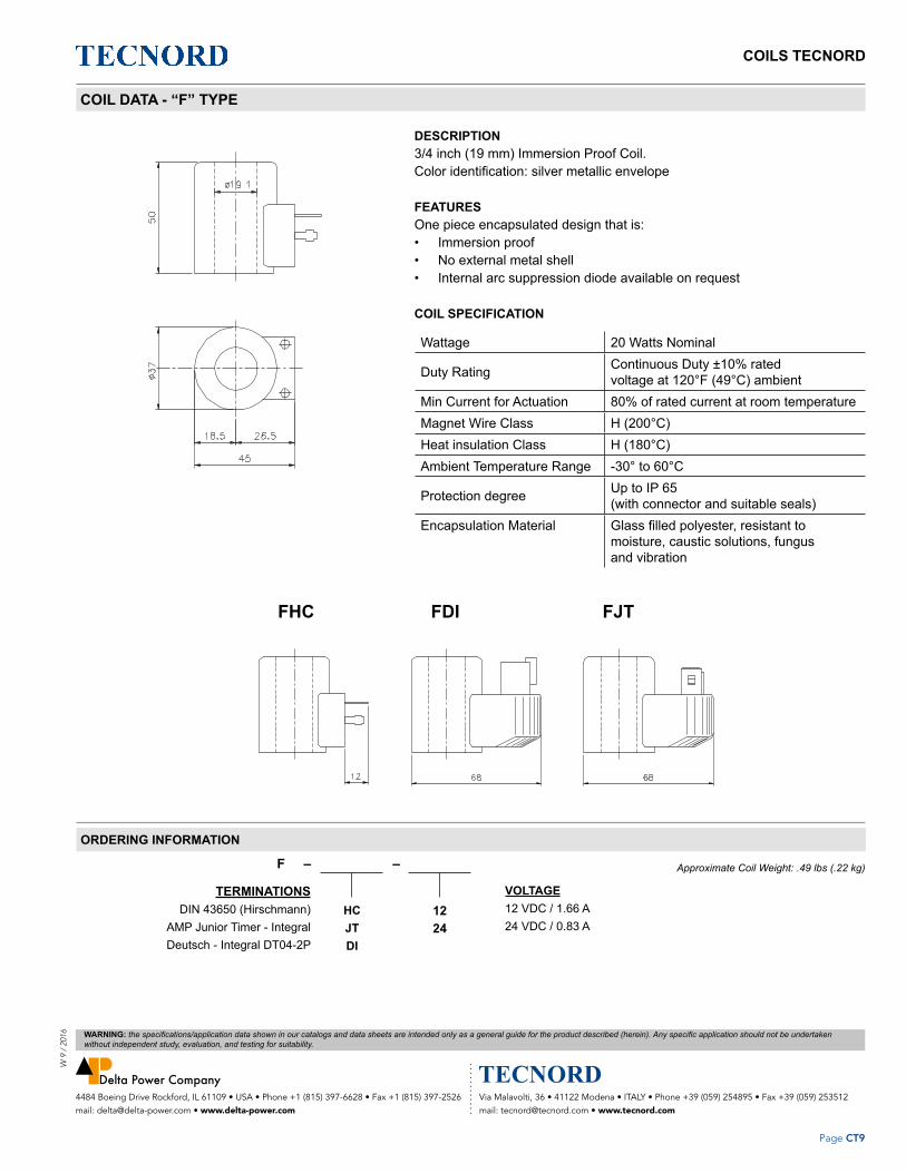
COILS TECNORDW
9 /
201
6
Page CT9
Via Malavolti, 36 • 41122 Modena • ITALY • Phone +39 (059) 254895 • Fax +39 (059) 253512 mail: [email protected] • www.tecnord.com
4484 Boeing Drive Rockford, IL 61109 • USA • Phone +1 (815) 397-6628 • Fax +1 (815) 397-2526 mail: [email protected] • www.delta-power.com
WARNING: the specifications/application data shown in our catalogs and data sheets are intended only as a general guide for the product described (herein). Any specific application should not be undertaken without independent study, evaluation, and testing for suitability.
COIL DATA - “F” TYPE
DESCRIPTION3/4 inch (19 mm) Immersion Proof Coil. Color identification: silver metallic envelope
FEATURES One piece encapsulated design that is:• Immersion proof• No external metal shell• Internal arc suppression diode available on request
COIL SPECIFICATION
Wattage 20 Watts Nominal
Duty Rating Continuous Duty ±10% ratedvoltage at 120°F (49°C) ambient
Min Current for Actuation 80% of rated current at room temperatureMagnet Wire Class H (200°C)Heat insulation Class H (180°C)Ambient Temperature Range -30° to 60°C
Protection degree Up to IP 65 (with connector and suitable seals)
Encapsulation Material Glass filled polyester, resistant to moisture, caustic solutions, fungus and vibration
TERMINATIONS DIN 43650 (Hirschmann) AMP Junior Timer - Integral Deutsch - Integral DT04-2P
F – –
HCJTDI
VOLTAGE12 VDC / 1.66 A24 VDC / 0.83 A
1224
Approximate Coil Weight: .49 lbs (.22 kg)
ORDERING INFORMATION
FHC FDI FJT
Z – –

COILS TECNORD
Page CT10
W 9 / 2016
Via Malavolti, 36 • 41122 Modena • ITALY • Phone +39 (059) 254895 • Fax +39 (059) 253512 mail: [email protected] • www.tecnord.com
4484 Boeing Drive Rockford, IL 61109 • USA • Phone +1 (815) 397-6628 • Fax +1 (815) 397-2526 mail: [email protected] • www.delta-power.com
WARNING: the specifications/application data shown in our catalogs and data sheets are intended only as a general guide for the product described (herein). Any specific application should not be undertaken without independent study, evaluation, and testing for suitability.
ACCESSORIES
TECHNICAL DATA
Number of poles 2 + Earth
Max operating current 10 A
Contact resistance < 4 mOhm
Max. wire cross section 1.5 mm2
Cable diameter 6 - 8 mm
Cable gland size Pg 9
Protection class IP 65
ORDERING INFORMATION
DESCRIPTION CODE
Standard 50.1004.002
With VDR resistor 50.1004.025
Standard connector dimensions and with internal VDR resistor against overvoltage peak
CONNECTORS FOR THE DIN 43650 (HIRSCHMANN) TERMINATION

ACCESSORIESW
9 /
201
6
Page AC1
Via Malavolti, 36 • 41122 Modena • ITALY • Phone +39 (059) 254895 • Fax +39 (059) 253512 mail: [email protected] • www.tecnord.com
4484 Boeing Drive Rockford, IL 61109 • USA • Phone +1 (815) 397-6628 • Fax +1 (815) 397-2526 mail: [email protected] • www.delta-power.com
WARNING: the specifications/application data shown in our catalogs and data sheets are intended only as a general guide for the product described (herein). Any specific application should not be undertaken without independent study, evaluation, and testing for suitability.
VALVE BODIES ...................................................................................................................................................... AC2
CAVITY PLUGS ...................................................................................................................................................... AC6
MANUAL OVERRIDE OPTIONS ........................................................................................................................... AC11
PILOT PISTON ASSEMBLIES .............................................................................................................................. AC13
STANDARD KNOB ASSEMBLIES ........................................................................................................................ AC14
Section / Description page
ACCESSORIES

ACCESSORIES
Page AC2
W 9 / 2016
Via Malavolti, 36 • 41122 Modena • ITALY • Phone +39 (059) 254895 • Fax +39 (059) 253512 mail: [email protected] • www.tecnord.com
4484 Boeing Drive Rockford, IL 61109 • USA • Phone +1 (815) 397-6628 • Fax +1 (815) 397-2526 mail: [email protected] • www.delta-power.com
WARNING: the specifications/application data shown in our catalogs and data sheets are intended only as a general guide for the product described (herein). Any specific application should not be undertaken without independent study, evaluation, and testing for suitability.
VALVE BODIES - TECNORD
STANDARD BODIES (ALUMINIUM)
PORT SIZE P/N STYLE / SIZE DIMENSIONS
A B C D E F
1/4 BSP 13.1011.002 3W-5/8 30 50 60 25 52 34
#6SAE 13.1011.142 3W-5/8 30 50 60 25 52 34
1/4 BSP 13.1011.124 2W-3/4 30 50 50 23 42 34
3/8 BSP 13.1011.125 2W-3/4 30 50 50 23 42 34
#6 SAE 13.1011.144 2W-3/4 30 50 50 23 42 34
3/8 BSP 13.1011.116 2W-7/8 30 60 60 25 52 44
1/2 BSP 13.1011.115 2W-7/8 30 60 60 25 52 44
#8 SAE 13.1011.147 2W-7/8 30 60 60 25 52 44
3/8 BSP 13.1011.118 3W-7/8 30 60 70 30 62 44
#6 SAE 13.1011.148 3W-7/8 30 60 70 30 62 44
3/8 BSP 13.1011.121 4W-7/8 30 60 85 30 77 44
#6 SAE 13.1011.149 4W-7/8 30 60 85 30 77 44
3/4 BSP 13.1011.130 2W-1 1/16 50 80 80 40 70 60
#12 SAE 13.1011.138 2W-1 1/16 50 80 80 40 70 60
3/4 BSP 13.1011.131 3W-1 1/16 50 80 100 40 80 60
#12 SAE 13.1011.139 3W-1 1/16 50 80 100 40 80 60
3/4 BSP 13.1011.008 2W-1 5/16 50 80 80 34 60 60
#12 SAE 13.1011.137 2W-1 5/16 50 80 80 34 60 60
3/4 BSP 13.1011.153 3W-1 5/16 50 80 100 40 80 60
3/4 BSP 13.1011.155 3W-1 5/16 SHORT 50 90 85 45 65 70
#12 SAE 13.1011.154 3W-1 5/16 50 80 100 40 80 60
3/8 BSP 13.1011.042/A 3W-cavity 042 30 70 80 35 72 54
1/4 BSP 13.1011.086 3W-cavity 043 40 60 50 30 40 40
#8 SAE 13.1011.191 3W-cavity 059 50 90 80 45 73 76
1/4 BSP 13.1011.080 3W-cavity 059 50 90 80 30 73 76
The following bodies are for the slip-in style cartridges. Contact factory for price and availability

ACCESSORIESW
9 /
201
6
Page AC3
Via Malavolti, 36 • 41122 Modena • ITALY • Phone +39 (059) 254895 • Fax +39 (059) 253512 mail: [email protected] • www.tecnord.com
4484 Boeing Drive Rockford, IL 61109 • USA • Phone +1 (815) 397-6628 • Fax +1 (815) 397-2526 mail: [email protected] • www.delta-power.com
WARNING: the specifications/application data shown in our catalogs and data sheets are intended only as a general guide for the product described (herein). Any specific application should not be undertaken without independent study, evaluation, and testing for suitability.
VALVE BODIES - TECNORD

ACCESSORIES
Page AC4
W 9 / 2016
Via Malavolti, 36 • 41122 Modena • ITALY • Phone +39 (059) 254895 • Fax +39 (059) 253512 mail: [email protected] • www.tecnord.com
4484 Boeing Drive Rockford, IL 61109 • USA • Phone +1 (815) 397-6628 • Fax +1 (815) 397-2526 mail: [email protected] • www.delta-power.com
WARNING: the specifications/application data shown in our catalogs and data sheets are intended only as a general guide for the product described (herein). Any specific application should not be undertaken without independent study, evaluation, and testing for suitability.
STANDARD BODIES - DELTA
BODY PORT SIZE P/N STYLE / SIZE DIMENSIONS
A B C D E F
AN 1/4 NPT 30102126 2W-5/8 1.25 2.0 1.5 1.0 1.0 1.5
AS #6 SAE 30102346 2W-5/8 1.25 2.0 1.5 1.0 1.0 1.5
CN 1/4 NPT 30102097 3W-5/8 1.25 2.0 2.25 1.0 1.875 1.5
CS #6SAE 30102373 3W-5/8 1.25 2.5 2.25 1.25 1.875 2.0
DN 1/4 NPT 30102110 4W-5/8 1.25 2.0 2.75 1.0 2.375 1.5
DS #6SAE 30102288 4W-5/8 1.25 2.0 2.75 1.125 2.375 1.5
BN 1/4 NPT 30102127 2W-3/4 1.25 2.0 2.0 1.0 1.5 1.5
BS #6SAE 30102466 2W-3/4 1.25 2.0 2.0 1.125 1.5 1.5
PN 1/4 NPT 30102534 3W-3/4 1.25 2.25 2.5 1.125 2.0 1.75
PS #6SAE 30102533 3W-3/4 1.25 2.25 2.5 1.125 2.0 1.75
QN 1/4 NPT 30102536 4W-3/4 1.25 2.25 3.0 1.125 2.5 1.75
QS #6SAE 30102535 4W-3/4 1.25 2.25 3.0 1.125 2.5 1.75
EN 3/8 NPT 30102006 2W-7/8 1.5 2.0 2.125 1.0 1.625 1.5
ES #8 SAE 30102359 2W-7/8 1.5 2.0 2.0 1.25 1.5 1.75
FN 1/4 NPT 30102015 3W-7/8 1.5 2.0 2.5 1.0 1.5 1.5
FS #6SAE 30102360 3W-7/8 1.5 2.5 2.5 1.25 2.125 2.25
GN 1/4 NPT 30102014 4W-7/8 1.5 2.0 3.25 1.0 2.125 1.5
GS #6SAE 30102367 4W-7/8 1.5 2.5 3.25 1.25 2.875 2.25
TS #12 SAE 30102813 2W-1 1/16 1.75 2.75 3.09 1.69 0.84 2.20
US #10 SAE 30102815 3W-1 1/16 1.75 3.0 3.87 1.5 2.0 2.30
RS #10 SAE 30102638 SHORT 3W-1 1/16 2.0 3.0 3.25 1.5 2.70 2.38
VS #10 SAE 30102816 4W-1 1/16 1.75 3.0 4.75 1.5 3.0 2.30
JN 3/4 NPT 30102334 2W-1 5/16 2.0 3.0 3.0 1.875 2.25 2.438
JS #12 SAE 301022331 2W-1 5/16 2.0 3.0 3.0 1.875 2.25 2.438
KS #12 SAE 30102576 3W-1 5/16 2.0 4.0 4.0 2.0 3.125 3.38
LS #12 SAE 30102575 SHORT 3W-1 5/16 2.0 3.5 3.5 1.875 2.75 2.88
NS #12 SAE 30102577 4W-1 5/16 2.0 4.0 5.25 2.0 4.25 3.38
OS #12 SAE 30102589 5W-1 5/16 2.0 4.0 5.75 2.0 4.75 3.38
E1/2 1/2 NPT 30102336 2W-7/8 1.5 2.5 2.5 1.50 2.0 2.0
E#6 #6 SAE 30102364 2W-7/8 1.5 2.0 2.0 1.25 1.50 1.75
F3/8 3/8 NPT 30102370 3W-7/8 1.5 2.0 2.5 1.25 2.125 2.25
F#8 #8 SAE 30102354 3W-7/8 1.5 2.5 2.75 1.25 2.125 2.00
G#8 #8 SAE 30102362 4W-7/8 1.5 2.0 2.25 1.25 2.875 2.25
J14 #14 SAE 30102332 2W-1 5/16 2.0 3.0 3.0 1.875 2.25 2.438
J16 #16 SAE 30102333 2W-1 5/16 2.0 3.0 3.0 1.875 2.25 2.438
The following bodies are for the slip-in style cartridges. Contact factory for price and availability

ACCESSORIESW
9 /
201
6
Page AC5
Via Malavolti, 36 • 41122 Modena • ITALY • Phone +39 (059) 254895 • Fax +39 (059) 253512 mail: [email protected] • www.tecnord.com
4484 Boeing Drive Rockford, IL 61109 • USA • Phone +1 (815) 397-6628 • Fax +1 (815) 397-2526 mail: [email protected] • www.delta-power.com
WARNING: the specifications/application data shown in our catalogs and data sheets are intended only as a general guide for the product described (herein). Any specific application should not be undertaken without independent study, evaluation, and testing for suitability.
STANDARD BODIES
OSDN - DS - NSCN, CS, KS, LS, RSAN, AS, BN, BS
ES, JN, JS, TS,
F
FS
F
CE
EN, E1/2, E#6
F
PN, PS, FN, US
F
EC
GS
F
CE
CE
F
E CE C
F
F
E C
B
D
A
B
D
F
CE
F
CE
E
A
D
B
A A
D
B
C
J14, J16
QN, QS, GN, VS, G#8

ACCESSORIES
Page AC6
W 9 / 2016
Via Malavolti, 36 • 41122 Modena • ITALY • Phone +39 (059) 254895 • Fax +39 (059) 253512 mail: [email protected] • www.tecnord.com
4484 Boeing Drive Rockford, IL 61109 • USA • Phone +1 (815) 397-6628 • Fax +1 (815) 397-2526 mail: [email protected] • www.delta-power.com
WARNING: the specifications/application data shown in our catalogs and data sheets are intended only as a general guide for the product described (herein). Any specific application should not be undertaken without independent study, evaluation, and testing for suitability.
MINI SERIES CAVITY PLUGS
MD SERIES
2.000[50.80]
4W 2P CAVITY PLUG
.875 HEX[22.22]
MA SERIES2W 2P CAVITY PLUG
[21.59]
.875 HEX
[5.56].219
[22.22]
[5.56].219
.496
.498
.850
Ø [12.60][12.65]
Ø.429.431
[12.60][12.65]
.496Ø.498
[10.90][10.95]
MC SERIES
1.400[35.56]
3W 2P CAVITY PLUG
.429 [10.90]
[22.22].875 HEX
[12.60][12.65]
.431
Ø
Ø
.496
.498
[10.95]
[5.56].219 Ø.370
.368[9.40][9.35]
NOTE: dimensions in brackets are millimeters
Standard Model Number2 Way3 Way4 Way
– –
MAMCMD
OptionsStandard BunaStandard Viton
00V0
ORDERING INFORMATION

ACCESSORIESW
9 /
201
6
Page AC7
Via Malavolti, 36 • 41122 Modena • ITALY • Phone +39 (059) 254895 • Fax +39 (059) 253512 mail: [email protected] • www.tecnord.com
4484 Boeing Drive Rockford, IL 61109 • USA • Phone +1 (815) 397-6628 • Fax +1 (815) 397-2526 mail: [email protected] • www.delta-power.com
WARNING: the specifications/application data shown in our catalogs and data sheets are intended only as a general guide for the product described (herein). Any specific application should not be undertaken without independent study, evaluation, and testing for suitability.
POWER SERIES CAVITY PLUGS
NOTE: dimensions in brackets are millimeters
Standard Model Number2 Way3 Way4 Way
– –
PBPPPQ
OptionsStandard BunaStandard Viton
00V0
ORDERING INFORMATION
4W 2P CAVITY PLUG
[22.22].875 HEX
[25.40]1.00 HEX
[41.00][5.56]1.614
[22.22].875 HEX
.219
.496
.498Ø [12.60]
[12.65]
.555Ø.557
[15.70].620 [15.75]
Ø.618
[14.10][14.15]
PP SERIES3W 2P CAVITY PLUG
[15.82][15.77]Ø.623
.621
[5.56].219
[53.29]2.098
PQ SERIES
[14.17][14.22]
[12.60][12.65]
Ø
.496Ø.498
.558
.560
[27.79]1.094
PB SERIES2W 2P CAVITY PLUG
[5.56].219

ACCESSORIES
Page AC8
W 9 / 2016
Via Malavolti, 36 • 41122 Modena • ITALY • Phone +39 (059) 254895 • Fax +39 (059) 253512 mail: [email protected] • www.tecnord.com
4484 Boeing Drive Rockford, IL 61109 • USA • Phone +1 (815) 397-6628 • Fax +1 (815) 397-2526 mail: [email protected] • www.delta-power.com
WARNING: the specifications/application data shown in our catalogs and data sheets are intended only as a general guide for the product described (herein). Any specific application should not be undertaken without independent study, evaluation, and testing for suitability.
DELTA SERIES CAVITY PLUGS
NOTE: dimensions in brackets are millimeters
Standard Model Number2 Way3 Way4 Way
– –
DEDFDG
OptionsStandard BunaStandard Viton
00V0
ORDERING INFORMATION
2.438[61.93]
4W 2P CAVITY PLUG
[25.40]1.00 HEX
[25.40]
DE SERIES
1.250[31.75]
2W 2P CAVITY PLUG
1.00 HEX
.219[5.56]
[5.56]
[25.40]
.219
[15.72][15.80]
.619Ø.622
.619Ø.622
[17.30][17.35]
.681Ø.683
[15.80][15.72]
DF SERIES
1.812[46.02]
3W 2P CAVITY PLUG
[18.97][18.90]Ø.747
Ø.683.681
.744
[17.30][17.35]
.219[5.56]
DG SERIES
Ø.622.619
[15.80][15.72]

ACCESSORIESW
9 /
201
6
Page AC9
Via Malavolti, 36 • 41122 Modena • ITALY • Phone +39 (059) 254895 • Fax +39 (059) 253512 mail: [email protected] • www.tecnord.com
4484 Boeing Drive Rockford, IL 61109 • USA • Phone +1 (815) 397-6628 • Fax +1 (815) 397-2526 mail: [email protected] • www.delta-power.com
WARNING: the specifications/application data shown in our catalogs and data sheets are intended only as a general guide for the product described (herein). Any specific application should not be undertaken without independent study, evaluation, and testing for suitability.
TECNORD SERIES CAVITY PLUGS
NOTE: dimensions in brackets are millimeters
Standard Model Number2 Way3 Way
3 Way Short 4 Way
– –
TTTUTRTV
OptionsStandard BunaStandard Viton
00V0
ORDERING INFORMATION
.310 [7.87]
1.902 [48.32]
1.38 HEX[35.1]
.310 [7.87]
2.200[55.88]
.310[7.87]
2.851[72.42]
.310[7.87]
3.809[96.75]
1.38 HEX[35.1]
1.38 HEX[35.1]
1.38 HEX[35.1]
TT SERIES2W 2P CAVITY PLUG
NOTE: DIMENSIONS IN BRACKETS ARE MILLIMETERS
TR SERIES3W 2P SHORT CAVITY PLUG
TU SERIES3W 2P CAVITY PLUG
TV SERIES4W 2P CAVITY PLUG
Ø.873.871
Ø.935.933
Ø.873.871
Ø.935.933
Ø.935.933
Ø.810.808
Ø.873.871
Ø.935.933
[22.17][22.12]
[23.75][23.70]
[23.75][23.70]
[22.17][22.12]
[23.75][23.70]
[20.57][20.52]
[23.75][23.70]
[22.17][22.12]
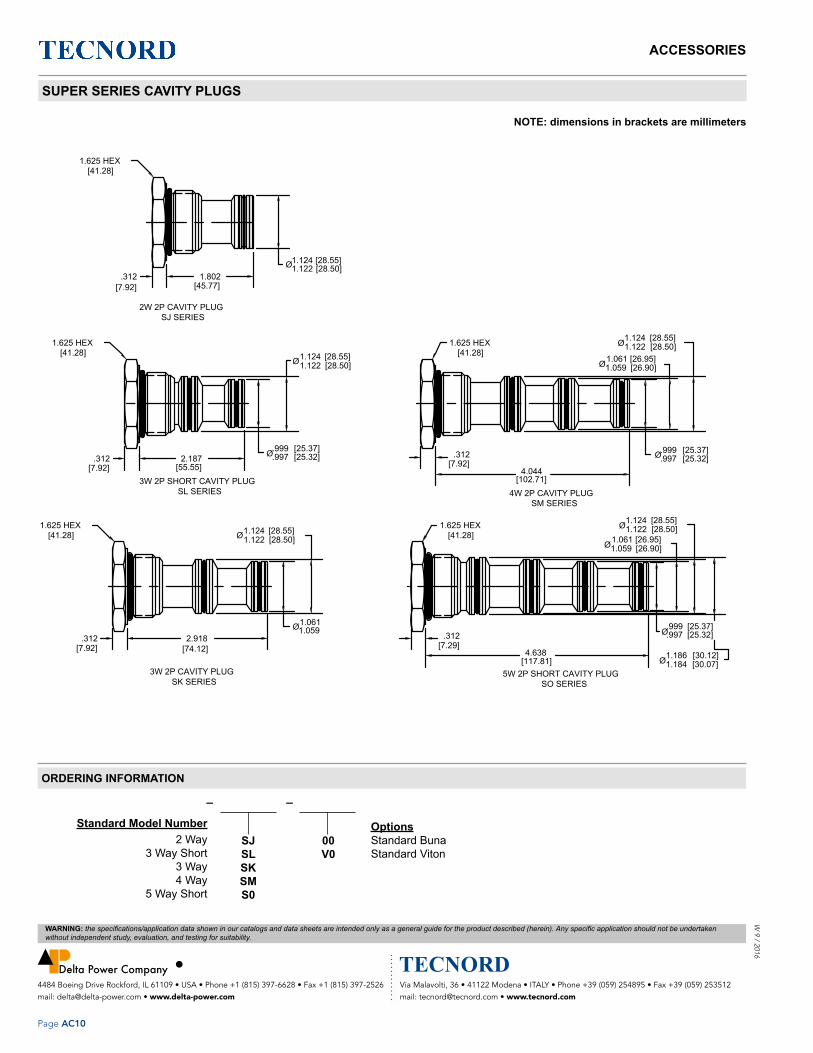
ACCESSORIES
Page AC10
W 9 / 2016
Via Malavolti, 36 • 41122 Modena • ITALY • Phone +39 (059) 254895 • Fax +39 (059) 253512 mail: [email protected] • www.tecnord.com
4484 Boeing Drive Rockford, IL 61109 • USA • Phone +1 (815) 397-6628 • Fax +1 (815) 397-2526 mail: [email protected] • www.delta-power.com
WARNING: the specifications/application data shown in our catalogs and data sheets are intended only as a general guide for the product described (herein). Any specific application should not be undertaken without independent study, evaluation, and testing for suitability.
SUPER SERIES CAVITY PLUGS
NOTE: dimensions in brackets are millimeters
Standard Model Number2 Way
3 Way Short3 Way4 Way
5 Way Short
– –
SJSLSKSMS0
OptionsStandard BunaStandard Viton
00V0
ORDERING INFORMATION
1.625 HEX[41.28]
[55.55]
2W 2P CAVITY PLUGSJ SERIES
2.187
[41.28]1.625 HEX
[7.92].312
[7.92].312
1.124 [28.55]
[45.77]1.802
[28.50]Ø1.124 [28.55]1.122
.999Ø.997[25.37][25.32]
Ø1.122 [28.50]
3W 2P SHORT CAVITY PLUGSL SERIES
1.625 HEX[41.28] Ø1.124
1.122[28.55][28.50]
3W 2P CAVITY PLUGSK SERIES
[7.92].312
[74.12]2.918
1.059Ø1.061
4.638[117.81]
5W 2P SHORT CAVITY PLUG
4W 2P CAVITY PLUG
[7.29].312
SO SERIES
1.625 HEX[41.28]
[7.92].312
[102.71]4.044
SM SERIES
[30.07][30.12]Ø1.184
1.186
[25.37].997 [25.32]Ø.999
[28.55][28.50]
[26.90]1.061 [26.95]1.059
1.1241.122
Ø
Ø
Ø [25.32].999 [25.37].997
Ø
1.625 HEX[41.28]
Ø1.122 [28.50]
[26.90][26.95]
1.0591.061
1.124 [28.55]

ACCESSORIESW
9 /
201
6
Page AC11
Via Malavolti, 36 • 41122 Modena • ITALY • Phone +39 (059) 254895 • Fax +39 (059) 253512 mail: [email protected] • www.tecnord.com
4484 Boeing Drive Rockford, IL 61109 • USA • Phone +1 (815) 397-6628 • Fax +1 (815) 397-2526 mail: [email protected] • www.delta-power.com
WARNING: the specifications/application data shown in our catalogs and data sheets are intended only as a general guide for the product described (herein). Any specific application should not be undertaken without independent study, evaluation, and testing for suitability.
MANUAL OVERRIDE OPTIONS
PULL TYPE MANUAL OVERRIDE OPTION
Pull Type Manual Override Option Standard override option for pull type solenoid valves.
This override is offered with or without the detent option.
With detent option, pull and rotate180 degrees, when released the override will remain in that position. To return to the normal operating position, Rotate knob 180 degrees and release.
Without the detent option, knob must be pulled and held to maintain override position.
PUSH TYPE MANUAL OVERRIDE OPTION
Standard push type override option used for 4W3P valves.
To activate override option, push knob and Hold, when released, the valve returns to normal operation position.
Note: override option only functions in the push (S1 coil) direction.
This override option is intended for emergency use only and is not intended for continuous duty operation.

ACCESSORIES
Page AC12
W 9 / 2016
Via Malavolti, 36 • 41122 Modena • ITALY • Phone +39 (059) 254895 • Fax +39 (059) 253512 mail: [email protected] • www.tecnord.com
4484 Boeing Drive Rockford, IL 61109 • USA • Phone +1 (815) 397-6628 • Fax +1 (815) 397-2526 mail: [email protected] • www.delta-power.com
WARNING: the specifications/application data shown in our catalogs and data sheets are intended only as a general guide for the product described (herein). Any specific application should not be undertaken without independent study, evaluation, and testing for suitability.
MANUAL OVERRIDE OPTIONS
ROTARY TYPE MANUAL OVERRIDE OPTION
Standard rotary override option for normally open valves.
This override option is offered with or without a knob.
To activate override option, fully rotate using a flat tip screwdriver or the knob in a clockwise direction.
To de-activate override, fully rotate using a flat tip screwdriver or the knob in a counter clockwise direction.
Note: not rotating override fully in either direction will result in partial shifting of valve.
WARNING: Over torque of manual override could result in valve damage.
Note: rotary Pull Type Manual Override Option (Pull type Valves-Reference Models HB-S2A & HB-S2B).
Because HB-S2A & HB-S2B are Pull type Valves, “fully in” is the normal state and “fully out” is “fully shifted” state so opposite of what is shown in image.”

ACCESSORIESW
9 /
201
6
Page AC13
Via Malavolti, 36 • 41122 Modena • ITALY • Phone +39 (059) 254895 • Fax +39 (059) 253512 mail: [email protected] • www.tecnord.com
4484 Boeing Drive Rockford, IL 61109 • USA • Phone +1 (815) 397-6628 • Fax +1 (815) 397-2526 mail: [email protected] • www.delta-power.com
WARNING: the specifications/application data shown in our catalogs and data sheets are intended only as a general guide for the product described (herein). Any specific application should not be undertaken without independent study, evaluation, and testing for suitability.
PILOT PISTON ASSEMBLIES
MINI SERIES POWER SERIES
DELTA SERIES SUPER SERIES .75
2.39
1.57.27
Ø.19
Ø.624
3.75
Ø1.12 Ø.25
Ø1.12
2.501.25
2.08
Ø.50
Ø.125.75
1.41.27
ABOREDIA.
ABOREDIA.
B"DOUBLE"
C"SINGLE"
2.4
Ø.50 Ø.13
.7501.58
DESCRIPTIONThese pistons are used in a manifold to create pilot operated valve assemblies, such as pilot operated checks.
FEATURES • O-rings on piston are optional.• One piece design or pressed fit dowel pins• Single or double pilot piston options.
PISTION SPECIFICATIONS
VALVE SERIES VALVE SERIES VALVE SERIESMINI .193 6.7:1
POWER .250 4:1
DELTA .312 4:1
SUPER .590 3.7:1
CAVITY INFORMATION SERIES BORE DIAMETER DOUBLE - SPOTFACE DIM. SINGLE - SPOTFACE DIM.
MINI SERIES POWER SERIES
DELTA SERIES SUPER SERIES .75
2.39
1.57.27
Ø.19
Ø.624
3.75
Ø1.12 Ø.25
Ø1.12
2.501.25
2.08
Ø.50
Ø.125.75
1.41.27
ABOREDIA.
ABOREDIA.
B"DOUBLE"
C"SINGLE"
2.4
Ø.50 Ø.13
.7501.58
A B C
MINI .500/.502 3.313 2.031
POWER .500/.502 4.250 2.406
DELTA .625/.627 4.500 2.750
SUPER 1.126/1.128 6.938 4.000
PISTONMINI Series .500 DIA
POWER Series .500 DIADELTA Series .625 DIA
SUPER Series 1.12 DIA
– – –
MPDS
SEALSBunaVitonOmit
PILOT PIN OPTIONSSingleDouble
BVO
SD
ORDERING INFORMATION
MINI SERIES POWER SERIES
DELTA SERIES SUPER SERIES .75
2.39
1.57.27
Ø.19
Ø.624
3.75
Ø1.12 Ø.25
Ø1.12
2.501.25
2.08
Ø.50
Ø.125.75
1.41.27
ABOREDIA.
ABOREDIA.
B"DOUBLE"
C"SINGLE"
2.4
Ø.50 Ø.13
.7501.58
MINI SERIES POWER SERIES
DELTA SERIES SUPER SERIES .75
2.39
1.57.27
Ø.19
Ø.624
3.75
Ø1.12 Ø.25
Ø1.12
2.501.25
2.08
Ø.50
Ø.125.75
1.41.27
ABOREDIA.
ABOREDIA.
B"DOUBLE"
C"SINGLE"
2.4
Ø.50 Ø.13
.7501.58

ACCESSORIES
Page AC14
W 9 / 2016
Via Malavolti, 36 • 41122 Modena • ITALY • Phone +39 (059) 254895 • Fax +39 (059) 253512 mail: [email protected] • www.tecnord.com
4484 Boeing Drive Rockford, IL 61109 • USA • Phone +1 (815) 397-6628 • Fax +1 (815) 397-2526 mail: [email protected] • www.delta-power.com
WARNING: the specifications/application data shown in our catalogs and data sheets are intended only as a general guide for the product described (herein). Any specific application should not be undertaken without independent study, evaluation, and testing for suitability.
STANDARD KNOB ASSEMBLIES
220200473450203266700059
MINI SERIES
34502000 DELTA SERIES
22020005 3450200636202008
DELTA SERIES
22020004345020043450200366700027
DELTA SERIES
220200033450200366700027
DELTA SERIES
34502008 DELTA SERIES
220200493450201766700059
DELTA SERIESSUPER SERIES
34502024 POWER SERIES
220200583450201966700059
POWER SERIES

ENGINEERING DATAW
9 /
201
6
Page ED1
Via Malavolti, 36 • 41122 Modena • ITALY • Phone +39 (059) 254895 • Fax +39 (059) 253512 mail: [email protected] • www.tecnord.com
4484 Boeing Drive Rockford, IL 61109 • USA • Phone +1 (815) 397-6628 • Fax +1 (815) 397-2526 mail: [email protected] • www.delta-power.com
WARNING: the specifications/application data shown in our catalogs and data sheets are intended only as a general guide for the product described (herein). Any specific application should not be undertaken without independent study, evaluation, and testing for suitability.
CAVITY DATA ......................................................................................................................................................... ED2
GENERAL INSTALLATION NOTE ......................................................................................................................... ED28
VALVE MNEMONIC CODE ..................................................................................................................................... ED30
Section / Description page
ENGINEERING DATA

ENGINEERING DATA
Page ED2
W 9 / 2016
Via Malavolti, 36 • 41122 Modena • ITALY • Phone +39 (059) 254895 • Fax +39 (059) 253512 mail: [email protected] • www.tecnord.com
4484 Boeing Drive Rockford, IL 61109 • USA • Phone +1 (815) 397-6628 • Fax +1 (815) 397-2526 mail: [email protected] • www.delta-power.com
WARNING: the specifications/application data shown in our catalogs and data sheets are intended only as a general guide for the product described (herein). Any specific application should not be undertaken without independent study, evaluation, and testing for suitability.
SERIES SIZE THREAD SIZE TOOLS KIT PAGE
T043 SLIP-IN K-T043 ED3
T059 SLIP-IN K-T059 ED4
T042 7/8-14 UNF 2B K-T042 ED5
MINI 2 WAY 7 5/8-18 UNF 2B 40500003 ED6
MINI 3 WAY 7 5/8-18 UNF 2B 40500004 ED7
MINI 4 WAY 7 5/8-18 UNF 2B 40500006 ED8
POWER 2 WAY 8 3/4-16 UNF 2B 40500005 ED9
POWER 3 WAY 8 3/4-16 UNF 2B 40500024 ED10
POWER 4 WAY 8 3/4-16 UNF 2B 40500029 ED11
DELTA 2 WAY 10 7/8-14 UNF 2B 40500000 ED12
DELTA 2 WAY SPECIAL 10 7/8-14 UNF 2B 40500028 ED13
DELTA 3 WAY 10 7/8-14 UNF 2B 40500001 ED14
DELTA 4 WAY 10 7/8-14 UNF 2B 40500002 ED15
TECNORD 2 WAY 12 1 1/16-12 UNF 2B 40500032 ED16
TECNORD 3 WAY SHORT 12 1 1/16-12 UNF 2B 40500033 ED17
TECNORD 3 WAY 12 1 1/16-12 UNF 2B 40500034 ED18
TECNORD 4 WAY 12 1 1/16-12 UNF 2B 40500035 ED19
TECNORD 5 WAY SHORT 12 1 1/16-12 UNF 2B 40500037 ED20
SUPER 2 WAY 16 1 5/16-12 UNF 2B 40500017 ED21
SUPER 3 WAY SHORT 16 1 5/16-12 UNF 2B 40500021 ED22
SUPER 3 WAY 16 1 5/16-12 UNF 2B 40500018 ED23
SUPER 4 WAY 16 1 5/16-12 UNF 2B 40500019 ED24
SUPER 5 WAY SHORT 16 1 5/16-12 UNF 2B 40500020 ED25
SUPER 5 WAY 16 1 5/16-12 UNF 2B 40500038 ED26
QS SPECIAL 3W 10 M20 X 1.5-H6 40500012 ED27
CAVITY DATA

ENGINEERING DATAW
9 /
201
6
Page ED3
Via Malavolti, 36 • 41122 Modena • ITALY • Phone +39 (059) 254895 • Fax +39 (059) 253512 mail: [email protected] • www.tecnord.com
4484 Boeing Drive Rockford, IL 61109 • USA • Phone +1 (815) 397-6628 • Fax +1 (815) 397-2526 mail: [email protected] • www.delta-power.com
WARNING: the specifications/application data shown in our catalogs and data sheets are intended only as a general guide for the product described (herein). Any specific application should not be undertaken without independent study, evaluation, and testing for suitability.
T043 SLIP-IN CAVITY FOR IP-DAR-43 CARTRIDGE
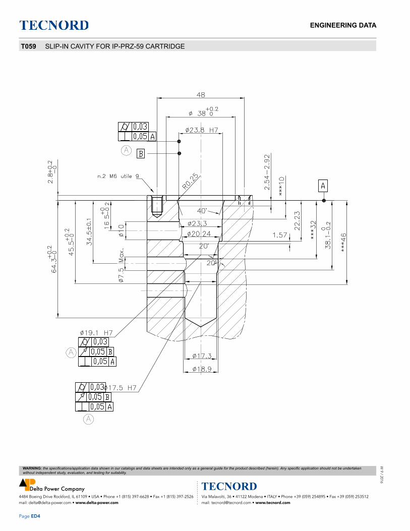
ENGINEERING DATA
Page ED4
W 9 / 2016
Via Malavolti, 36 • 41122 Modena • ITALY • Phone +39 (059) 254895 • Fax +39 (059) 253512 mail: [email protected] • www.tecnord.com
4484 Boeing Drive Rockford, IL 61109 • USA • Phone +1 (815) 397-6628 • Fax +1 (815) 397-2526 mail: [email protected] • www.delta-power.com
WARNING: the specifications/application data shown in our catalogs and data sheets are intended only as a general guide for the product described (herein). Any specific application should not be undertaken without independent study, evaluation, and testing for suitability.
T059 SLIP-IN CAVITY FOR IP-PRZ-59 CARTRIDGE

ENGINEERING DATAW
9 /
201
6
Page ED5
Via Malavolti, 36 • 41122 Modena • ITALY • Phone +39 (059) 254895 • Fax +39 (059) 253512 mail: [email protected] • www.tecnord.com
4484 Boeing Drive Rockford, IL 61109 • USA • Phone +1 (815) 397-6628 • Fax +1 (815) 397-2526 mail: [email protected] • www.delta-power.com
WARNING: the specifications/application data shown in our catalogs and data sheets are intended only as a general guide for the product described (herein). Any specific application should not be undertaken without independent study, evaluation, and testing for suitability.
T042 CAVITY FOR EG-TRZ-42 CARTRIDGE, 7/8” - 14 THREAD

ENGINEERING DATA
Page ED6
W 9 / 2016
Via Malavolti, 36 • 41122 Modena • ITALY • Phone +39 (059) 254895 • Fax +39 (059) 253512 mail: [email protected] • www.tecnord.com
4484 Boeing Drive Rockford, IL 61109 • USA • Phone +1 (815) 397-6628 • Fax +1 (815) 397-2526 mail: [email protected] • www.delta-power.com
WARNING: the specifications/application data shown in our catalogs and data sheets are intended only as a general guide for the product described (herein). Any specific application should not be undertaken without independent study, evaluation, and testing for suitability.
MINI 2W 7 SIZE, 5/8-18 THREAD “MINI” SERIES
30°
20°
45°
Ø1.062
Ø.760.750
Ø.649.645
Ø.571.567
Ø.502.500
MAX.Ø.312
PORT ZONE
.002 B
.002 B
.002 B
.001 A.001
.001 A.002 B
.031 REFERENCE TYPICAL
.109
.094 .875
.500 Ø.312PORT ZONE
STANDARD SERIES
.3755/8-18 UNF-2B
.500
Ø.213 PORT ZONE FORHIGH PRESSURE SERIES
32
-A-
-B-
NOTES:
1. CAVITY CAN BE MACHINED WITH DELTA FORM TOOL #40500003.
2. ALL MACHINED SURFACES TO BE 32√ FINISH OR BETTER, EXCLUDING THREADS.
3. IT IS VERY IMPORTANT THAT VALVE CAVITIES MEET ALL DIMENSIONAL AND QUALITY
STANDARDS OF CONCENTRICITY AND PERPENDICULARITY. THREADS MUST BE
PERPENDICULAR TO THE SPOTFACE SURFACE. SPOTFACE MUST CLEAN UP TO FULL
DIAMETER. IMPROPERLY MACHINED CAVITIES CAN LEAD TO CARTRIDGE MALFUNCTION
AND/OR FAILURE FROM DISTORTION.
4. PORT ZONE IS Ø.213 MAXIMUM AT PORT #1 ONLY FOR BHIGH PRESSURE SERIES MINI
VALVES (HA-***-**).

ENGINEERING DATAW
9 /
201
6
Page ED7
Via Malavolti, 36 • 41122 Modena • ITALY • Phone +39 (059) 254895 • Fax +39 (059) 253512 mail: [email protected] • www.tecnord.com
4484 Boeing Drive Rockford, IL 61109 • USA • Phone +1 (815) 397-6628 • Fax +1 (815) 397-2526 mail: [email protected] • www.delta-power.com
WARNING: the specifications/application data shown in our catalogs and data sheets are intended only as a general guide for the product described (herein). Any specific application should not be undertaken without independent study, evaluation, and testing for suitability.
MINI 3W 7 SIZE, 5/8-18 THREAD “MINI” SERIES
30°
45°
20°
20°
Ø1.062
.002 B
.002 B
.002 B
.001 A
.031 REFERENCE TYPICAL.109.094
1.057
.213PORT ZONE
1.062
1.437
.500 Ø.312PORT ZONE
STANDARD SERIES
Ø.312 MAX. PORT ZONE
.001.001 B
.001.001 A
.375
.002 B
.500
Ø.213 PORT ZONE FORHIGH PRESSURE SERIES
32
5/8-18 UNF-2B
Ø.649.645
Ø.571.567
.750Ø.760
Ø.439.437
.500Ø.502
-A-
-B-
NOTES:
1. CAVITY CAN BE MACHINED WITH DELTA FORM TOOL #40500004.
2. ALL MACHINED SURFACES TO BE 32√ FINISH OR BETTER, EXCLUDING THREADS.
3. IT IS VERY IMPORTANT THAT VALVE CAVITIES MEET ALL DIMENSIONAL AND QUALITY
STANDARDS OF CONCENTRICITY AND PERPENDICULARITY. THREADS MUST BE
PERPENDICULAR TO THE SPOTFACE SURFACE. SPOTFACE MUST CLEAN UP TO FULL
DIAMETER. IMPROPERLY MACHINED CAVITIES CAN LEAD TO CARTRIDGE MALFUNCTION
AND/OR FAILURE FROM DISTORTION.
4. PORT ZONE IS Ø.213 MAXIMUM AT PORT #1 ONLY FOR BHIGH PRESSURE SERIES MINI
VALVES (HA-***-**).

ENGINEERING DATA
Page ED8
W 9 / 2016
Via Malavolti, 36 • 41122 Modena • ITALY • Phone +39 (059) 254895 • Fax +39 (059) 253512 mail: [email protected] • www.tecnord.com
4484 Boeing Drive Rockford, IL 61109 • USA • Phone +1 (815) 397-6628 • Fax +1 (815) 397-2526 mail: [email protected] • www.delta-power.com
WARNING: the specifications/application data shown in our catalogs and data sheets are intended only as a general guide for the product described (herein). Any specific application should not be undertaken without independent study, evaluation, and testing for suitability.
MINI 4W 7 SIZE, 5/8-18 THREAD “MINI” SERIES
30°
45°
20°
20°
29°
Ø1.062
.002 B
.002 B
.002 B
.001
.001 A
.3755/8-18 UNF-2B
.001 A
.002 B
.031 REFERENCE TYPICAL
.525
1.118
1.7182.062
.494
.985
1.695
.250PORT ZONE
(3X)
Ø.312 MAX. PORT ZONE
.001 B
.001 B
32
Ø.502.500
.567Ø.571
Ø.649.645
.750Ø.760
Ø.377.375
Ø.439.437
.109
.094
-A-
-B-
NOTES:
1. CAVITY CAN BE MACHINED WITH DELTA FORM TOOL #40500006.
2. ALL MACHINED SURFACES TO BE 32√ FINISH OR BETTER, EXCLUDING THREADS.
3. IT IS VERY IMPORTANT THAT VALVE CAVITIES MEET ALL DIMENSIONAL AND QUALITY
STANDARDS OF CONCENTRICITY AND PERPENDICULARITY. THREADS MUST BE
PERPENDICULAR TO THE SPOTFACE SURFACE. SPOTFACE MUST CLEAN UP TO FULL
DIAMETER. IMPROPERLY MACHINED CAVITIES CAN LEAD TO CARTRIDGE MALFUNCTION
AND/OR FAILURE FROM DISTORTION.

ENGINEERING DATAW
9 /
201
6
Page ED9
Via Malavolti, 36 • 41122 Modena • ITALY • Phone +39 (059) 254895 • Fax +39 (059) 253512 mail: [email protected] • www.tecnord.com
4484 Boeing Drive Rockford, IL 61109 • USA • Phone +1 (815) 397-6628 • Fax +1 (815) 397-2526 mail: [email protected] • www.delta-power.com
WARNING: the specifications/application data shown in our catalogs and data sheets are intended only as a general guide for the product described (herein). Any specific application should not be undertaken without independent study, evaluation, and testing for suitability.
POWER 2 WAY 8 SIZE, 3/4-16 THREAD “POWER” SERIES
Ø.375 MAX PORT ZONE
PORT ZONE.375
30°20°
1.125
.860.800
.100
.115
.031 REFERENCE TYPICAL
.738
.689Ø.685
Ø.811.816
45°
15°
.502Ø.500
Ø1.188
.002 B
.002 B
R.030
3/4-16 UNF-2B .562
.001 A.002 B
.001 A.001
32
-A-
-B-
NOTES:
1. CAVITY CAN BE MACHINED WITH DELTA FORM TOOL #40500005.
2. ALL MACHINED SURFACES TO BE 32√ FINISH OR BETTER, EXCLUDING THREADS.
3. IT IS VERY IMPORTANT THAT VALVE CAVITIES MEET ALL DIMENSIONAL AND QUALITY
STANDARDS OF CONCENTRICITY AND PERPENDICULARITY. THREADS MUST BE
PERPENDICULAR TO THE SPOTFACE SURFACE. SPOTFACE MUST CLEAN UP TO FULL
DIAMETER. IMPROPERLY MACHINED CAVITIES CAN LEAD TO CARTRIDGE MALFUNCTION
AND/OR FAILURE FROM DISTORTION.

ENGINEERING DATA
Page ED10
W 9 / 2016
Via Malavolti, 36 • 41122 Modena • ITALY • Phone +39 (059) 254895 • Fax +39 (059) 253512 mail: [email protected] • www.tecnord.com
4484 Boeing Drive Rockford, IL 61109 • USA • Phone +1 (815) 397-6628 • Fax +1 (815) 397-2526 mail: [email protected] • www.delta-power.com
WARNING: the specifications/application data shown in our catalogs and data sheets are intended only as a general guide for the product described (herein). Any specific application should not be undertaken without independent study, evaluation, and testing for suitability.
POWER 3 WAY 8 SIZE, 3/4-16 THREAD “POWER” SERIES
45°
20°
20°30°
Ø1.188
15°
.002 B
.002 B
R.010
.001 A.002 B
1.250
Ø.219PORT ZONE
.031 REFERENCE TYPICAL
.115
.110.675
PORT ZONEØ.250
.710
1.270
1.656
.001 A.001
.001 B.001
3/4-16 UNF-2B .562
Ø.375MAX. PORT ZONE
32
Ø.816.811
Ø.689.685
Ø.564.562
Ø.627.625
-A-
-B-
NOTES:
1. CAVITY CAN BE MACHINED WITH DELTA FORM TOOL #40500024.
2. ALL MACHINED SURFACES TO BE 32√ FINISH OR BETTER, EXCLUDING THREADS.
3. IT IS VERY IMPORTANT THAT VALVE CAVITIES MEET ALL DIMENSIONAL AND QUALITY
STANDARDS OF CONCENTRICITY AND PERPENDICULARITY. THREADS MUST BE
PERPENDICULAR TO THE SPOTFACE SURFACE. SPOTFACE MUST CLEAN UP TO FULL
DIAMETER. IMPROPERLY MACHINED CAVITIES CAN LEAD TO CARTRIDGE MALFUNCTION
AND/OR FAILURE FROM DISTORTION.

ENGINEERING DATAW
9 /
201
6
Page ED11
Via Malavolti, 36 • 41122 Modena • ITALY • Phone +39 (059) 254895 • Fax +39 (059) 253512 mail: [email protected] • www.tecnord.com
4484 Boeing Drive Rockford, IL 61109 • USA • Phone +1 (815) 397-6628 • Fax +1 (815) 397-2526 mail: [email protected] • www.delta-power.com
WARNING: the specifications/application data shown in our catalogs and data sheets are intended only as a general guide for the product described (herein). Any specific application should not be undertaken without independent study, evaluation, and testing for suitability.
POWER 4 WAY 8 SIZE, 3/4-16 THREAD “POWER” SERIES
PORTZONE
PORTZONE
ZONEPORT
20°
20°
45°
Ø1.188
R.010
Ø.438 MAX. PORT ZONE
.031 REF. TYP.
.698.115.110
.7501.235
Ø.219
1.820
1.875
.673
Ø.219
1.257
1.312
1.798
2.125Ø.219
R.01015°
.5623/4-16 UNF-2B
.001 A.002 B
.002 B
.001 B
.001 B
.001
.001
.001 B.001
.001.001 A
R.010
32
Ø.816.811
.682Ø.690
.625Ø.627
Ø.564.562
Ø.502.500
-A-
-B-
NOTES:
1. CAVITY CAN BE MACHINED WITH DELTA FORM TOOL #40500029.
2. ALL MACHINED SURFACES TO BE 32√ FINISH OR BETTER, EXCLUDING THREADS.
3. IT IS VERY IMPORTANT THAT VALVE CAVITIES MEET ALL DIMENSIONAL AND QUALITY
STANDARDS OF CONCENTRICITY AND PERPENDICULARITY. THREADS MUST BE
PERPENDICULAR TO THE SPOTFACE SURFACE. SPOTFACE MUST CLEAN UP TO FULL
DIAMETER. IMPROPERLY MACHINED CAVITIES CAN LEAD TO CARTRIDGE MALFUNCTION
AND/OR FAILURE FROM DISTORTION.

ENGINEERING DATA
Page ED12
W 9 / 2016
Via Malavolti, 36 • 41122 Modena • ITALY • Phone +39 (059) 254895 • Fax +39 (059) 253512 mail: [email protected] • www.tecnord.com
4484 Boeing Drive Rockford, IL 61109 • USA • Phone +1 (815) 397-6628 • Fax +1 (815) 397-2526 mail: [email protected] • www.delta-power.com
WARNING: the specifications/application data shown in our catalogs and data sheets are intended only as a general guide for the product described (herein). Any specific application should not be undertaken without independent study, evaluation, and testing for suitability.
DELTA 2 WAY 10 SIZE, 7/8-14 THREAD “DELTA” SERIES
*
Ø1.188.002 B
.002 B
.001 A
.001
15°
.001 A.002 B
.031 REFERENCE TYPICAL
1.312
.937.850
.438PORT ZONE
.062
.115
.110
Ø.563MAX.
PORT ZONE
20°
45°
.031 R.MAX.
.015 R.
.020 R.
.005 R.
.010 R.
20°.625
32
7/8-14 UNF-2A
Ø.947.942
Ø.814.810
Ø.627.625
-A-
-B-
NOTES:
1. CAVITY CAN BE MACHINED WITH DELTA FORM TOOL #40500000.
2. ALL MACHINED SURFACES TO BE 32√ FINISH OR BETTER, EXCLUDING THREADS.
3. IT IS VERY IMPORTANT THAT VALVE CAVITIES MEET ALL DIMENSIONAL AND QUALITY
STANDARDS OF CONCENTRICITY AND PERPENDICULARITY. THREADS MUST BE
PERPENDICULAR TO THE SPOTFACE SURFACE. SPOTFACE MUST CLEAN UP TO FULL
DIAMETER. IMPROPERLY MACHINED CAVITIES CAN LEAD TO CARTRIDGE MALFUNCTION
AND/OR FAILURE FROM DISTORTION.

ENGINEERING DATAW
9 /
201
6
Page ED13
Via Malavolti, 36 • 41122 Modena • ITALY • Phone +39 (059) 254895 • Fax +39 (059) 253512 mail: [email protected] • www.tecnord.com
4484 Boeing Drive Rockford, IL 61109 • USA • Phone +1 (815) 397-6628 • Fax +1 (815) 397-2526 mail: [email protected] • www.delta-power.com
WARNING: the specifications/application data shown in our catalogs and data sheets are intended only as a general guide for the product described (herein). Any specific application should not be undertaken without independent study, evaluation, and testing for suitability.
DELTA 2 WAY SPECIAL 10 SIZE, 7/8-14 THREAD “DELTA” SERIES
15°
45°
30°
Ø1.188
.031 REFERENCE TYPICAL
1.378
.630 MAX.PORT ZONE
.748
1.469
2.047
PORT ZONEØ.630 MAX.
.002 B
.002 B
7/8-14 UNF-2B.001 A
.002 B
.001 A.001
R.01032
.115
.110
.942Ø.947
.810Ø.814
Ø.750.748
-A-
-B-
NOTES:
1. CAVITY CAN BE MACHINED WITH DELTA FORM TOOL #40500028.
2. ALL MACHINED SURFACES TO BE 32√ FINISH OR BETTER, EXCLUDING THREADS.
3. IT IS VERY IMPORTANT THAT VALVE CAVITIES MEET ALL DIMENSIONAL AND QUALITY
STANDARDS OF CONCENTRICITY AND PERPENDICULARITY. THREADS MUST BE
PERPENDICULAR TO THE SPOTFACE SURFACE. SPOTFACE MUST CLEAN UP TO FULL
DIAMETER. IMPROPERLY MACHINED CAVITIES CAN LEAD TO CARTRIDGE MALFUNCTION
AND/OR FAILURE FROM DISTORTION.

ENGINEERING DATA
Page ED14
W 9 / 2016
Via Malavolti, 36 • 41122 Modena • ITALY • Phone +39 (059) 254895 • Fax +39 (059) 253512 mail: [email protected] • www.tecnord.com
4484 Boeing Drive Rockford, IL 61109 • USA • Phone +1 (815) 397-6628 • Fax +1 (815) 397-2526 mail: [email protected] • www.delta-power.com
WARNING: the specifications/application data shown in our catalogs and data sheets are intended only as a general guide for the product described (herein). Any specific application should not be undertaken without independent study, evaluation, and testing for suitability.
DELTA 3 WAY 10 SIZE, 7/8-14 THREAD “DELTA” SERIES
NOTES:
1. CAVITY CAN BE MACHINED WITH DELTA FORM TOOL #40500001.
2. ALL MACHINED SURFACES TO BE 32√ FINISH OR BETTER, EXCLUDING THREADS.
3. IT IS VERY IMPORTANT THAT VALVE CAVITIES MEET ALL DIMENSIONAL AND QUALITY
STANDARDS OF CONCENTRICITY AND PERPENDICULARITY. THREADS MUST BE
PERPENDICULAR TO THE SPOTFACE SURFACE. SPOTFACE MUST CLEAN UP TO FULL
DIAMETER. IMPROPERLY MACHINED CAVITIES CAN LEAD TO CARTRIDGE MALFUNCTION
AND/OR FAILURE FROM DISTORTION.
Ø1.188
15°
.002 B
.002 B
.001 A.002 B
.031 REFERENCE TYPICAL
.115
.110 .850 .910
1.464
.250 PORT ZONE
1.500 1.5601.875
.806.375
PORT ZONE
.005 R.
.010 R.
R.030
45°
2X20°
PORT ZONEØ.563 MAX.
.001.001 B
.001.001 A
.625
R.010
32
7/8-14 UNF-2B
Ø.947.942
Ø.814.810
Ø.627.625
Ø.690.688
-A-
-B-

ENGINEERING DATAW
9 /
201
6
Page ED15
Via Malavolti, 36 • 41122 Modena • ITALY • Phone +39 (059) 254895 • Fax +39 (059) 253512 mail: [email protected] • www.tecnord.com
4484 Boeing Drive Rockford, IL 61109 • USA • Phone +1 (815) 397-6628 • Fax +1 (815) 397-2526 mail: [email protected] • www.delta-power.com
WARNING: the specifications/application data shown in our catalogs and data sheets are intended only as a general guide for the product described (herein). Any specific application should not be undertaken without independent study, evaluation, and testing for suitability.
DELTA 4 WAY 10 SIZE, 7/8-14 THREAD “DELTA” SERIES
45°
20°
(3)PORT ZONE
PORT ZONE
Ø1.188
15°
.002 B
.002 B
.001 A.001
.001 A.002 B
.031 REFERENCE TYPICAL
.115
.110.860
1.464
Ø.250 PORT ZONE
1.4852.093
2.500
2.094
.813
Ø.375
Ø.250
.005 R.
.010 R.
Ø.563 MAX.PORT ZONE
.001.001 B
.001 B.001
32
7/8-14 UNF-2B .625
.942Ø.947
Ø.814.810
Ø.752.750
Ø.627.625
Ø.690.688
-A-
-B-
NOTES:
1. CAVITY CAN BE MACHINED WITH DELTA FORM TOOL #40500002.
2. ALL MACHINED SURFACES TO BE 32√ FINISH OR BETTER, EXCLUDING THREADS.
3. IT IS VERY IMPORTANT THAT VALVE CAVITIES MEET ALL DIMENSIONAL AND QUALITY
STANDARDS OF CONCENTRICITY AND PERPENDICULARITY. THREADS MUST BE
PERPENDICULAR TO THE SPOTFACE SURFACE. SPOTFACE MUST CLEAN UP TO FULL
DIAMETER. IMPROPERLY MACHINED CAVITIES CAN LEAD TO CARTRIDGE MALFUNCTION
AND/OR FAILURE FROM DISTORTION.

ENGINEERING DATA
Page ED16
W 9 / 2016
Via Malavolti, 36 • 41122 Modena • ITALY • Phone +39 (059) 254895 • Fax +39 (059) 253512 mail: [email protected] • www.tecnord.com
4484 Boeing Drive Rockford, IL 61109 • USA • Phone +1 (815) 397-6628 • Fax +1 (815) 397-2526 mail: [email protected] • www.delta-power.com
WARNING: the specifications/application data shown in our catalogs and data sheets are intended only as a general guide for the product described (herein). Any specific application should not be undertaken without independent study, evaluation, and testing for suitability.
TECNORD 2 WAY 12 SIZE, 1 1/16-12 THREAD “TECNORD” SERIES
NOTES:
1. CAVITY CAN BE MACHINED WITH DELTA FORM TOOL #40500032.
2. ALL MACHINED SURFACES TO BE 32√ FINISH OR BETTER, EXCLUDING THREADS.
3. IT IS VERY IMPORTANT THAT VALVE CAVITIES MEET ALL DIMENSIONAL AND QUALITY
STANDARDS OF CONCENTRICITY AND PERPENDICULARITY. THREADS MUST BE
PERPENDICULAR TO THE SPOTFACE SURFACE. SPOTFACE MUST CLEAN UP TO FULL
DIAMETER. IMPROPERLY MACHINED CAVITIES CAN LEAD TO CARTRIDGE MALFUNCTION
AND/OR FAILURE FROM DISTORTION.
.005R.010
.875 MAXPORT ZONE
.145
.130
1.400
1.460REF.
1.920
-A-
45°
20°
.031 REFERENCE TYPICAL
1.345
.690 MAXPORT ZONE
Ø1.625
.002 B
.002 B
-B-
.001 A.001
15°
1 1/16-12 UN-2B .81
.001 A.002 B
32
.937Ø.939
.972Ø.978
1.148Ø1.152

ENGINEERING DATAW
9 /
201
6
Page ED17
Via Malavolti, 36 • 41122 Modena • ITALY • Phone +39 (059) 254895 • Fax +39 (059) 253512 mail: [email protected] • www.tecnord.com
4484 Boeing Drive Rockford, IL 61109 • USA • Phone +1 (815) 397-6628 • Fax +1 (815) 397-2526 mail: [email protected] • www.delta-power.com
WARNING: the specifications/application data shown in our catalogs and data sheets are intended only as a general guide for the product described (herein). Any specific application should not be undertaken without independent study, evaluation, and testing for suitability.
TECNORD 3 WAY SHORT 12 SIZE, 1 1/16-12 THREAD “TECNORD” SERIES
NOTES:
1. CAVITY CAN BE MACHINED WITH DELTA FORM TOOL #40500033.
2. ALL MACHINED SURFACES TO BE 32√ FINISH OR BETTER, EXCLUDING THREADS.
3. IT IS VERY IMPORTANT THAT VALVE CAVITIES MEET ALL DIMENSIONAL AND QUALITY
STANDARDS OF CONCENTRICITY AND PERPENDICULARITY. THREADS MUST BE
PERPENDICULAR TO THE SPOTFACE SURFACE. SPOTFACE MUST CLEAN UP TO FULL
DIAMETER. IMPROPERLY MACHINED CAVITIES CAN LEAD TO CARTRIDGE MALFUNCTION
AND/OR FAILURE FROM DISTORTION.
.145
.130.849.900
REF.
1.838
1.900REF.
2.250
-A-
.812 MAXPORT ZONE
20°
R.010
20°
45°
1.782
.031 REFERENCE TYPICAL
.813
.500 PORTZONE
.250 PORT ZONE
R.010
Ø1.625
Ø1.1521.148
.002 B
Ø.978.972
.002 B
Ø.939.937
-B-
.001 A.001
Ø.877.875
.001 B.001
15°
.661 1/16-2 UN-2B
.001 A .002 B
32

ENGINEERING DATA
Page ED18
W 9 / 2016
Via Malavolti, 36 • 41122 Modena • ITALY • Phone +39 (059) 254895 • Fax +39 (059) 253512 mail: [email protected] • www.tecnord.com
4484 Boeing Drive Rockford, IL 61109 • USA • Phone +1 (815) 397-6628 • Fax +1 (815) 397-2526 mail: [email protected] • www.delta-power.com
WARNING: the specifications/application data shown in our catalogs and data sheets are intended only as a general guide for the product described (herein). Any specific application should not be undertaken without independent study, evaluation, and testing for suitability.
TECNORD 3 WAY 12 SIZE, 1 1/16-12 THREAD “TECNORD” SERIES
.005R.010
.145
.130
1.400
1.460REF.
2.370
2.430REF.
2.890
-A-
.812 MAXPORT ZONE
R.010
.001 B.001
20° (2X)
45°
.500PORT ZONE
.500PORT ZONE
2.340
1.370
.031 REFERENCE TYPICAL
Ø1.625.002 B
.002 B
-B-
.001 A.001
15°
.811 1/16-12 UN-2B
.001 A.002 B
32
1.148Ø1.152
.972Ø.978
Ø.939.937
Ø.877.875
NOTES:
1. CAVITY CAN BE MACHINED WITH DELTA FORM TOOL #40500034.
2. ALL MACHINED SURFACES TO BE 32√ FINISH OR BETTER, EXCLUDING THREADS.
3. IT IS VERY IMPORTANT THAT VALVE CAVITIES MEET ALL DIMENSIONAL AND QUALITY
STANDARDS OF CONCENTRICITY AND PERPENDICULARITY. THREADS MUST BE
PERPENDICULAR TO THE SPOTFACE SURFACE. SPOTFACE MUST CLEAN UP TO FULL
DIAMETER. IMPROPERLY MACHINED CAVITIES CAN LEAD TO CARTRIDGE MALFUNCTION
AND/OR FAILURE FROM DISTORTION.

ENGINEERING DATAW
9 /
201
6
Page ED19
Via Malavolti, 36 • 41122 Modena • ITALY • Phone +39 (059) 254895 • Fax +39 (059) 253512 mail: [email protected] • www.tecnord.com
4484 Boeing Drive Rockford, IL 61109 • USA • Phone +1 (815) 397-6628 • Fax +1 (815) 397-2526 mail: [email protected] • www.delta-power.com
WARNING: the specifications/application data shown in our catalogs and data sheets are intended only as a general guide for the product described (herein). Any specific application should not be undertaken without independent study, evaluation, and testing for suitability.
TECNORD 4 WAY 12 SIZE, 1 1/16-12 THREAD “TECNORD” SERIES
.005
.010R
(3X)
DETAIL 'A'
1.400
1.460REF.
2.370
2.430REF.
3.330
3.390REF.
3.860
-A-
.750MAX.PORT ZONE
20°
.500PORT ZONE
.500PORT ZONE
.500PORT ZONE
1.370
2.340
3.310
.031 REFERENCE TYPICAL
SEE DETAIL 'A'
.001 B.001
.001 B.001
Ø1.625
.002 B
.002 B
15° -B-
.001 A.001
45°
1 1/16-12 UN-2B .81
.001 A.002 B
R.010
32.145.130
Ø.877.875
Ø.814.812
Ø.939.937
Ø.978.972
Ø1.1521.148
NOTES:
1. CAVITY CAN BE MACHINED WITH DELTA FORM TOOL #40500035.
2. ALL MACHINED SURFACES TO BE 32√ FINISH OR BETTER, EXCLUDING THREADS.
3. IT IS VERY IMPORTANT THAT VALVE CAVITIES MEET ALL DIMENSIONAL AND QUALITY
STANDARDS OF CONCENTRICITY AND PERPENDICULARITY. THREADS MUST BE
PERPENDICULAR TO THE SPOTFACE SURFACE. SPOTFACE MUST CLEAN UP TO FULL
DIAMETER. IMPROPERLY MACHINED CAVITIES CAN LEAD TO CARTRIDGE MALFUNCTION
AND/OR FAILURE FROM DISTORTION.

ENGINEERING DATA
Page ED20
W 9 / 2016
Via Malavolti, 36 • 41122 Modena • ITALY • Phone +39 (059) 254895 • Fax +39 (059) 253512 mail: [email protected] • www.tecnord.com
4484 Boeing Drive Rockford, IL 61109 • USA • Phone +1 (815) 397-6628 • Fax +1 (815) 397-2526 mail: [email protected] • www.delta-power.com
WARNING: the specifications/application data shown in our catalogs and data sheets are intended only as a general guide for the product described (herein). Any specific application should not be undertaken without independent study, evaluation, and testing for suitability.
TECNORD 5 WAY SHORT 12 SIZE, 1 1/16-12 THREAD “TECNORD” SERIES
NOTES:
1. CAVITY CAN BE MACHINED WITH DELTA FORM TOOL #40500037.
2. ALL MACHINED SURFACES TO BE 32√ FINISH OR BETTER, EXCLUDING THREADS.
3. IT IS VERY IMPORTANT THAT VALVE CAVITIES MEET ALL DIMENSIONAL AND QUALITY
STANDARDS OF CONCENTRICITY AND PERPENDICULARITY. THREADS MUST BE
PERPENDICULAR TO THE SPOTFACE SURFACE. SPOTFACE MUST CLEAN UP TO FULL
DIAMETER. IMPROPERLY MACHINED CAVITIES CAN LEAD TO CARTRIDGE MALFUNCTION
AND/OR FAILURE FROM DISTORTION.
.130+.015-.000
PORTZONE
45°
NO
.063
DETAIL "A"
20°
BURRS
R.010
DETAIL "B"
20°
.060
SEE DETAIL "A"
SEE "B"
PORTZONE
.688 MAXPORT ZONE
.001 B.001
Ø1.625
.002 B
.002 B
-B-
.001 B.001
.6601 1/16-12 UN-2B .001 A
.002 B
15°
R.010/.005
3.730
2.760
.500
1.790
.500
.813
.031 REF. TYPICAL
.500
-A- 32
46
46
.812Ø.814
Ø.877.875
Ø.939.937
.972Ø.978
1.148Ø1.152
Ø.752.750
PORTZONE
PORTZONE
.250
.001 B.001
.001 B.001
.849(.900)
1.820(1.883)
2.790(2.855)
3.760
(3.823)
4.280

ENGINEERING DATAW
9 /
201
6
Page ED21
Via Malavolti, 36 • 41122 Modena • ITALY • Phone +39 (059) 254895 • Fax +39 (059) 253512 mail: [email protected] • www.tecnord.com
4484 Boeing Drive Rockford, IL 61109 • USA • Phone +1 (815) 397-6628 • Fax +1 (815) 397-2526 mail: [email protected] • www.delta-power.com
WARNING: the specifications/application data shown in our catalogs and data sheets are intended only as a general guide for the product described (herein). Any specific application should not be undertaken without independent study, evaluation, and testing for suitability.
SUPER 2 WAY 16 SIZE, 1 5/16-12 THREAD “SUPER” SERIES
NOTES:
1. CAVITY CAN BE MACHINED WITH DELTA FORM TOOL #40500017.
2. ALL MACHINED SURFACES TO BE 32√ FINISH OR BETTER, EXCLUDING THREADS.
3. IT IS VERY IMPORTANT THAT VALVE CAVITIES MEET ALL DIMENSIONAL AND QUALITY
STANDARDS OF CONCENTRICITY AND PERPENDICULARITY. THREADS MUST BE
PERPENDICULAR TO THE SPOTFACE SURFACE. SPOTFACE MUST CLEAN UP TO FULL
DIAMETER. IMPROPERLY MACHINED CAVITIES CAN LEAD TO CARTRIDGE MALFUNCTION
AND/OR FAILURE FROM DISTORTION.
Ø1.910
1.4031.399
15°.031 REFERENCE TYPICAL
.130
.145
1.305 1.344
1.844
.062
1.2361.232
1.1261.128
45°
20°
Ø1.000 MAX PORT ZONE
PORT ZONEØ.750
DETAIL 'A'R .030
SEE DETAIL 'A'
.8751 5/16-12 UNF-2B
.001 A.002 B
Ø
.002 B
.001 A.001
Ø
.002 BØ
32
-A-
-B-

ENGINEERING DATA
Page ED22
W 9 / 2016
Via Malavolti, 36 • 41122 Modena • ITALY • Phone +39 (059) 254895 • Fax +39 (059) 253512 mail: [email protected] • www.tecnord.com
4484 Boeing Drive Rockford, IL 61109 • USA • Phone +1 (815) 397-6628 • Fax +1 (815) 397-2526 mail: [email protected] • www.delta-power.com
WARNING: the specifications/application data shown in our catalogs and data sheets are intended only as a general guide for the product described (herein). Any specific application should not be undertaken without independent study, evaluation, and testing for suitability.
SUPER 3 WAY SHORT 16 SIZE, 1 5/16-12 THREAD “SUPER” SERIES
NOTES:
1. CAVITY CAN BE MACHINED WITH DELTA FORM TOOL #40500021.
2. ALL MACHINED SURFACES TO BE 32√ FINISH OR BETTER, EXCLUDING THREADS.
3. IT IS VERY IMPORTANT THAT VALVE CAVITIES MEET ALL DIMENSIONAL AND QUALITY
STANDARDS OF CONCENTRICITY AND PERPENDICULARITY. THREADS MUST BE
PERPENDICULAR TO THE SPOTFACE SURFACE. SPOTFACE MUST CLEAN UP TO FULL
DIAMETER. IMPROPERLY MACHINED CAVITIES CAN LEAD TO CARTRIDGE MALFUNCTION
AND/OR FAILURE FROM DISTORTION.
DETAIL 'A'
Ø1.910
Ø.938 MAXPORT ZONE
1.780
.782
.031 REFERENCE TYPICAL
.562 PORT ZONE
.250 PORT ZONE
.688.812
1.812
2.188
-A-
.002 B
.002 B
.001 B.001
-B- .001 A.001
SEE DETAIL 'A'
R.0
1045°
1 5/16-12 UNF-2B
.001 A.002 B
15°
.063
20°
R.030
NO BURRS
3232
32
46
46
1.126Ø1.128
1.232Ø1.236
1.399Ø1.403
.145
.130
Ø1.0031.001

ENGINEERING DATAW
9 /
201
6
Page ED23
Via Malavolti, 36 • 41122 Modena • ITALY • Phone +39 (059) 254895 • Fax +39 (059) 253512 mail: [email protected] • www.tecnord.com
4484 Boeing Drive Rockford, IL 61109 • USA • Phone +1 (815) 397-6628 • Fax +1 (815) 397-2526 mail: [email protected] • www.delta-power.com
WARNING: the specifications/application data shown in our catalogs and data sheets are intended only as a general guide for the product described (herein). Any specific application should not be undertaken without independent study, evaluation, and testing for suitability.
SUPER 3 WAY 16 SIZE, 1 5/16-12 THREAD “SUPER” SERIES
Ø 1.2321.236
DETAIL 'B'
.063
20° 20°
.063
Ø1.910
.002 B
.002 B
.001 B.001
.001 A.001
-B-
Ø1.000 MAX.PORT ZONE
1.281
2.405
Ø.625PORT ZONE (2X)
45°.875
1.344
2.469
2.968
-A-
15°
SEE DETAIL 'A'
SEE DETAIL 'B'
1 5/16-12 UNF-2B
R.010
.001 A.002 B
R.030
NO BURRSR.010
NO BURRS
DETAIL 'A'
3232
.031 REFERENCE TYPICAL
32
46
4646
.145
.130
Ø1.0651.063
Ø1.1281.126
Ø1.4031.399
NOTES:
1. CAVITY CAN BE MACHINED WITH DELTA FORM TOOL #40500018.
2. ALL MACHINED SURFACES TO BE 32√ FINISH OR BETTER, EXCLUDING THREADS.
3. IT IS VERY IMPORTANT THAT VALVE CAVITIES MEET ALL DIMENSIONAL AND QUALITY
STANDARDS OF CONCENTRICITY AND PERPENDICULARITY. THREADS MUST BE
PERPENDICULAR TO THE SPOTFACE SURFACE. SPOTFACE MUST CLEAN UP TO FULL
DIAMETER. IMPROPERLY MACHINED CAVITIES CAN LEAD TO CARTRIDGE MALFUNCTION
AND/OR FAILURE FROM DISTORTION.

ENGINEERING DATA
Page ED24
W 9 / 2016
Via Malavolti, 36 • 41122 Modena • ITALY • Phone +39 (059) 254895 • Fax +39 (059) 253512 mail: [email protected] • www.tecnord.com
4484 Boeing Drive Rockford, IL 61109 • USA • Phone +1 (815) 397-6628 • Fax +1 (815) 397-2526 mail: [email protected] • www.delta-power.com
WARNING: the specifications/application data shown in our catalogs and data sheets are intended only as a general guide for the product described (herein). Any specific application should not be undertaken without independent study, evaluation, and testing for suitability.
SUPER 4 WAY 16 SIZE, 1 5/16-12 THREAD “SUPER” SERIES
20°
.063 R.010
NO BURRS
DETAIL 'A'
DETAIL 'B'
NO BURRS
R.030
20°
Ø.938 MAXPORT ZONE
3.531
2.406
1.281
.625(3X)PORT ZONE
.031 REFERENCE TYPICAL
Ø1.910
.002 B
.002 B
.001 B.001
.001.001 B
.001 A.001
-B-
4.094
3.594
2.469
1.344
.875
-A-
45°
SEE DETAIL 'A'
SEE DETAIL 'B'
1 5/16-12 UNF-2B
R.0
10
.001 A.002 B
15°
.063
32
3232
32
46
4646
1.399Ø1.403
1.232Ø1.236
1.126Ø1.128
Ø1.0651.063
Ø1.0031.001
.145
.130
NOTES:
1. CAVITY CAN BE MACHINED WITH DELTA FORM TOOL #40500019.
2. ALL MACHINED SURFACES TO BE 32√ FINISH OR BETTER, EXCLUDING THREADS.
3. IT IS VERY IMPORTANT THAT VALVE CAVITIES MEET ALL DIMENSIONAL AND QUALITY
STANDARDS OF CONCENTRICITY AND PERPENDICULARITY. THREADS MUST BE
PERPENDICULAR TO THE SPOTFACE SURFACE. SPOTFACE MUST CLEAN UP TO FULL
DIAMETER. IMPROPERLY MACHINED CAVITIES CAN LEAD TO CARTRIDGE MALFUNCTION
AND/OR FAILURE FROM DISTORTION.

ENGINEERING DATAW
9 /
201
6
Page ED25
Via Malavolti, 36 • 41122 Modena • ITALY • Phone +39 (059) 254895 • Fax +39 (059) 253512 mail: [email protected] • www.tecnord.com
4484 Boeing Drive Rockford, IL 61109 • USA • Phone +1 (815) 397-6628 • Fax +1 (815) 397-2526 mail: [email protected] • www.delta-power.com
WARNING: the specifications/application data shown in our catalogs and data sheets are intended only as a general guide for the product described (herein). Any specific application should not be undertaken without independent study, evaluation, and testing for suitability.
Ø.938 MAX.PORT ZONE
.812
1.937
3.062
4.187
4.688
SEE DETAIL 'A'
4.125
3.000
1.875
.782
-A-
.625(3X) PORT ZONE
.250 PORTZONE
SEE DETAIL 'B'
.031 REFERENCE TYPICAL
Ø1.910
.002 B
.002 B
-B- .001 A.001
.001 B.001
.001.001 B
.001.001 B
45°
1 5/16-12 UNF-2B .688
.001 A.002 B
15°
DETAIL 'A'
DETAIL 'B'
20°
.060
20°
.063
R.010 NO BURRS
R.010
32
46
46
46
1.232Ø1.236
Ø1.1901.188
1.126Ø1.128
1.063Ø1.065
Ø1.4031.399
1.001Ø1.003
.145
.130
SUPER 5 WAY SHORT 16 SIZE, 1 5/16-12 THREAD “SUPER” SERIES
NOTES:
1. CAVITY CAN BE MACHINED WITH DELTA FORM TOOL #40500020.
2. ALL MACHINED SURFACES TO BE 32√ FINISH OR BETTER, EXCLUDING THREADS.
3. IT IS VERY IMPORTANT THAT VALVE CAVITIES MEET ALL DIMENSIONAL AND QUALITY
STANDARDS OF CONCENTRICITY AND PERPENDICULARITY. THREADS MUST BE
PERPENDICULAR TO THE SPOTFACE SURFACE. SPOTFACE MUST CLEAN UP TO FULL
DIAMETER. IMPROPERLY MACHINED CAVITIES CAN LEAD TO CARTRIDGE MALFUNCTION
AND/OR FAILURE FROM DISTORTION.

ENGINEERING DATA
Page ED26
W 9 / 2016
Via Malavolti, 36 • 41122 Modena • ITALY • Phone +39 (059) 254895 • Fax +39 (059) 253512 mail: [email protected] • www.tecnord.com
4484 Boeing Drive Rockford, IL 61109 • USA • Phone +1 (815) 397-6628 • Fax +1 (815) 397-2526 mail: [email protected] • www.delta-power.com
WARNING: the specifications/application data shown in our catalogs and data sheets are intended only as a general guide for the product described (herein). Any specific application should not be undertaken without independent study, evaluation, and testing for suitability.
SUPER 5 WAY 16 SIZE, 1 5/16-12 THREAD “SUPER” SERIES
.031
1.3441.281
3.532
3.594
4.657
4.719
5.220
.625PORT ZONE
5X
.002 B
.002 B
.002 B.001
.002 B.001
.001
.002 A.001
.9061 5/16-12 UNF-2B .001 A
.002 B
15°
.060
20°
DETAIL 'A'
SEE DETAIL 'A'
46
1.001Ø1.003
.145
.130
1.905Ø1.915
1.399Ø1.403
Ø1.2361.232
1.188Ø1.190
1.126Ø1.128
1.063Ø1.065
2.407
2.469
-A-
-B-
NOTES:
1. CAVITY CAN BE MACHINED WITH DELTA FORM TOOL #40500038.
2. ALL MACHINED SURFACES TO BE 32√ FINISH OR BETTER, EXCLUDING THREADS.
3. IT IS VERY IMPORTANT THAT VALVE CAVITIES MEET ALL DIMENSIONAL AND QUALITY
STANDARDS OF CONCENTRICITY AND PERPENDICULARITY. THREADS MUST BE
PERPENDICULAR TO THE SPOTFACE SURFACE. SPOTFACE MUST CLEAN UP TO FULL
DIAMETER. IMPROPERLY MACHINED CAVITIES CAN LEAD TO CARTRIDGE MALFUNCTION
AND/OR FAILURE FROM DISTORTION.

ENGINEERING DATAW
9 /
201
6
Page ED27
Via Malavolti, 36 • 41122 Modena • ITALY • Phone +39 (059) 254895 • Fax +39 (059) 253512 mail: [email protected] • www.tecnord.com
4484 Boeing Drive Rockford, IL 61109 • USA • Phone +1 (815) 397-6628 • Fax +1 (815) 397-2526 mail: [email protected] • www.delta-power.com
WARNING: the specifications/application data shown in our catalogs and data sheets are intended only as a general guide for the product described (herein). Any specific application should not be undertaken without independent study, evaluation, and testing for suitability.
MAX PORT ZONE
LOCATING SHOULDER
.835Ø .831
DETAIL 'A'
.001 A.001
.002 B
.001 B.001
45°
.001 B.001
.001 B.001
.562
45°
45°
.750
1.3821.078
.656
.182.438
.421
1.063Ø.688 MAX.PORT ZONE
PORT ZONEØ.406 MAX.
M20 X 1.5-H6.001 A
.002 B
30° SEE DETAIL 'A'
1.002.998
Ø.861.859
Ø.814.812
Ø.689.687
Ø.734.730
-A-
-A-
-B-
QS SPECIAL 3 WAY METRIC M20-1.5-H6 THREAD “SPECIAL” SERIES
NOTES:
1. CAVITY CAN BE MACHINED WITH DELTA FORM TOOL #40500012.
2. ALL MACHINED SURFACES TO BE 32√ FINISH OR BETTER, EXCLUDING THREADS.
3. IT IS VERY IMPORTANT THAT VALVE CAVITIES MEET ALL DIMENSIONAL AND QUALITY
STANDARDS OF CONCENTRICITY AND PERPENDICULARITY. THREADS MUST BE
PERPENDICULAR TO THE SPOTFACE SURFACE. SPOTFACE MUST CLEAN UP TO FULL
DIAMETER. IMPROPERLY MACHINED CAVITIES CAN LEAD TO CARTRIDGE MALFUNCTION
AND/OR FAILURE FROM DISTORTION.

ENGINEERING DATA
Page ED28
W 9 / 2016
Via Malavolti, 36 • 41122 Modena • ITALY • Phone +39 (059) 254895 • Fax +39 (059) 253512 mail: [email protected] • www.tecnord.com
4484 Boeing Drive Rockford, IL 61109 • USA • Phone +1 (815) 397-6628 • Fax +1 (815) 397-2526 mail: [email protected] • www.delta-power.com
WARNING: the specifications/application data shown in our catalogs and data sheets are intended only as a general guide for the product described (herein). Any specific application should not be undertaken without independent study, evaluation, and testing for suitability.
GENERAL INSTALLATION NOTE
VALVE BODIES
Check the cartridge brochure to assure correct plumbing.
Inspect the cavity for burrs and any irregular machining which would damage 0-rings at assembly.
Shims may be required behind the block for panel mounting.
ASSEMBLY
Dip the cartridge in clean oil before installing.
Screw the cartridge in by hand until the top 0-ring is touching to the proper torque specification the manifold, then wrench tighten given below.
TORQUE SPECIFICATIONS
Final Cartridge Tightening: Adjusting Holding Parts:
Series Torque
5/8 MINI 14-20 Nm (10-15 ft-lbs)
3/4 POWER 27-34 Nm (20-25 ft-lbs)
7/8 DELTA 34-40 Nm (25-30 ft-lbs)
1 1/16 TECNORD 81-95 Nm (60-70 ft-lbs)
1 5/16 SUPER 108-122 Nm (80-90 ft-lbs)
Part Torque
Nut 4-8 Nm (3-5 ft-lbs)
Knob 4-8 Nm (3-5 ft-lbs)

ENGINEERING DATAW
9 /
201
6
Page ED29
Via Malavolti, 36 • 41122 Modena • ITALY • Phone +39 (059) 254895 • Fax +39 (059) 253512 mail: [email protected] • www.tecnord.com
4484 Boeing Drive Rockford, IL 61109 • USA • Phone +1 (815) 397-6628 • Fax +1 (815) 397-2526 mail: [email protected] • www.delta-power.com
WARNING: the specifications/application data shown in our catalogs and data sheets are intended only as a general guide for the product described (herein). Any specific application should not be undertaken without independent study, evaluation, and testing for suitability.
GENERAL CARTRIDGE VALVE INSTALLATION NOTES
CARTRIDGES
Inspect the cartridge to assure there is no external contaminant present.Check O-rings and back-up rings to assure they are intact and in the correct position. The O-rings should always be toward the high pressure port or between doubled back-up rings on bidirectional applications.
COILS
It is sometimes easier to remove the coil from the cartridge valve to install terminations or make connections with conduit, etc. If this is the case, reinstall the coil by tightening the coil nut to 4-6 ft lbs per spec sheet. CAUTION: DO NOT OVER TORQUE Tube will be stretched and damaged, causing valve to fail.
VALVE BODIES
Check the cartridge brochure to assure correct plumbing. Inspect the cavity for burrs and any irregular machining which would damage 0-rings at assembly. Shims may be required behind the block for panel mounting.
ASSEMBLY
Dip the cartridge in clean oil before installing.Screw the cartridge in by hand until the top 0-ring is touching the manifold, then wrench tighten to the proper torque specification given below.

ENGINEERING DATA
Page ED30
W 9 / 2016
Via Malavolti, 36 • 41122 Modena • ITALY • Phone +39 (059) 254895 • Fax +39 (059) 253512 mail: [email protected] • www.tecnord.com
4484 Boeing Drive Rockford, IL 61109 • USA • Phone +1 (815) 397-6628 • Fax +1 (815) 397-2526 mail: [email protected] • www.delta-power.com
WARNING: the specifications/application data shown in our catalogs and data sheets are intended only as a general guide for the product described (herein). Any specific application should not be undertaken without independent study, evaluation, and testing for suitability.
VALVE MNEMONIC CODE
First letter is the valve series:M = MINI (5/8”)P = POWER (3/4”)D = DELTA (7/8”)T = TECNORD (1 1/16”)S = SUPER (1 5/16”)
I = INLINE/UNITIZEDE = ELECTRONIC PROPORTIONALA = MOTORIZEDQ = SPECIALSH = 4000/5000 PSI RATED
The third letter is the type of valve:R = RELIEFC = CHECK & LOAD HOLDINGN = NEEDLEP = PRESSURE CONTROLLED
S = SOLENOIDM = MANUALF = FLOW CONTROL
The third, fourth, and fifth characters combined describe the valve function. It is these characters that are stampes on the valve. Examples:
S2A = SOLENOID 2 WAY POPPETS3A = SOLENOID 3 WAY SPOOLS4A = SOLENOID 4 WAY CRISS SPOOLRVA = RELIEF DIRECT ACTINGMCB = MAN NC DETENT
P2A = PROPORTIONAL 2 WAYPRP = PRESSURE REDUCINGCVC = GUIDED BALL CHECKFCH = FLOW CONT REV FLOWNVB = NEEDLE COARSE ADJ
The sixth and seventh characters combined cover the o-ring, screen, override, knob and other options. Example:
00 = STANDARD DEFAULT CONFIGURATIONVK = VITON O-RINGS, KNOB ADJUSTMENTB3 = BUNA, SCREEN, OVERRIDE NONDETENT
The eighth througn eleventh characters describe the solenoid, flow range, or pressure range. Pressure or flow is specified as a range or a particular setting. Example:
DL12 = DUAL LEAD 12 VDCDS24 = DUAL SPADE 24VDCHC24 = HIRSCHMANN 24 VDCCL11 = CONDUIT LEAD 120VAC
0005 = 5 PSI CRACK1500 = 1500 MAX PRESS03.0 = 3 GPM MAX FLOW6-10 = 6 TO 10 G.P.M. FLOW RANGE
The final character is the body port style:N = BSP / NPTS = SAE
MINI POWER DELTA TECNORD SUPER2 WAY A B E T J3 WAY C P F U K
3 Way Short R L4 WAY D Q G V N
5 Way Short X O5 Way I
The second letter is the cavity: M= Inline S= Special
M A
- R V
A - V
K - 1
5 0
0 - S
D E
- S 2
A - 0
M - H
C 1
2 - N
1 2
- 3 4
5 - 6
7 - 8
9 10 11 - 1
2