catalogue 5.03 english - · rotech is specialized in producing and distributing signal devices,...
TRANSCRIPT

MA
NU
AL
5.03 E

This manual is intended for use as a catalogue and refe-rence for users of ROTECH products.
We have tried to give a short overview of a diversity ofproducts, regardless of manufacturer.
The different solutions are displayed in the most conveni-ent way, sorted by branch.
This manual is changed often so always reflect the latestdevelopments. Thererfore we encourage all readers tosubmit any kind of suggestions or comments.
This ROTECH-manual for systemcomponents is completely designednew and is protected by copyright.All rights reserved.
No part of this manual may be repro-duced or transmitted in any form orby any means, electronical or me-chanical.
Claims for conformity with the appli-cations shown in this manual are on-ly provided in accordance with theusual general guarantee.Further claims are excluded, notablyROTECH does not grant for the ac-curacy of the manual.
Technical data, dimensions and avai-labilitiy are subject to change.
ROTECH GmbHP.O. Box 761D - 76261 ETTLINGENTelefon: +49 (0) 72 43 - 5931 - 0Telefax: +49 (0) 72 43 - 5931 - 31e-mail: [email protected]: http://www.rotech.de

Solenoid Valves
Signal Devices
C
D
Brackets And Couplings
A
PositionersE
Signal Devices Open DesignB
AccessoriesF
IndexG


Signal Devices A
General A 1
TCR-class with A 2-1Microswitches A 2-33-wire – double sensors A 2-53-wire – proximity sensors A 2-73-wire – proximity switches cubic shape A 2-9Intrinsically safe slotted sensors (NAMUR) A 2-11Intrinsically safe double sensors (NAMUR) A 2-13EEx ed IIC T6 - switchbox A 2-15
Actuator – Sensor – Interface A 2-17TCR-Modul with AS-Interface A 2-19
Connections for solenoid valves A 2-21Plug connector A 2-22
PB-class with A 3-1Microswitches A 3-33-wire – double sensors A 3-53-wire – proximity switches cubic shape A 3-9Intrinsically safe slotted sensors (NAMUR) A 3-11Intrinsically safe sensors cubic shape (NAMUR) A 3-15
ET-class with A 4-1Microswitches A 4-13-wire – proximity sensors A 4-3Intrinsically safe slotted sensors (NAMUR) A 4-5
Brackets for signal devices A 5-1Universal-quick mounting bracket A 5-3TCR-brackets A 5-7Standard - ET - brackets A 5-10
AOverview


Signal Devices Open Design B
General B 1
Universal mounting plate for open design B 2
Switchcams and position indicators B 3Switchcams B 3-2Spacer rings B 3-4Position indicators B 3-4
ET-Kit (open mounted) with B 4mechanical operated signal devices B 4-1mechanical operated signal devices EEx d B 4-5contact free operated signal devices B 4-7
M12-plug connectors B 4-12
BOverview


Brackets C1with double-sided equal flanges steel, zinc-plated C 1-3
high grade steel(1.4301) C 1-4with different flanges steel, zinc-plated C 1-5
high grade steel(1.4301) C 1-6
Flang data according to DIN ISO 5211 C 1-7
Couplings C2Couplings standard-line C 2-3Couplings Eco-line C 2-4Valve connection by double-D C 2-5Valve connection by square C 2-7
Adapter sleeves C 3Square C 3-1
Adapter plates for flanges C 4Adapter plates for different flanges C 4-1Clearance flange plates C 4-2
COverview


Magnetic Solenoid Valves D
Manufacturer Airtec D 23/2-way magnetic solenoid valve D 2-15/2-way magnetic solenoid valve D 2-2
Manufacturer FESTO D 33/2-way magnetic solenoid valve D 3-15/2-way magnetic solenoid valve D 3-2
Manufacturer Herion D 43/2- and 5/2-way magnetic solenoid valve 26 230 79 D 4-33/2- and 5/2-way magnetic solenoid valvel 97 105 D 4-53/2- and 5/2-way magnetic solenoid valve 97 100 D 4-7
Manufacturer Samsomatic D 53/2-way magnetic solenoid valve D 5-15/2-way magnetic solenoid valve D 5-2
No-name-magnetic solenoid valve D 63/2-way magnetic solenoid valve D 6-15/2-way magnetic solenoid valve D 6-2
DOverview


Positioners E
Manufacturer Siemens E 1SIPART PS2 E 1-1Accessories E 1-2
Manufacturer Samson E 2TYP 3767 E 2-1Accessories E 2-2
EOverview

FOverview
Accessories F
Silencers F 1-1
Flow reducing silencers F 1-2
Solenoid plugs F 1-3
Adapterplates for solenoids F 1-4
Flow reducer plates F 1-5
Tube screw connections F 1-7
Compressed-air hose F 1-8
Manual emergency gears F 2-1
Deaeration for manual emergency gears F 2-3

Another activity is our build upservice. You are able to obtain thecomplete valve mounted with allnecessary components.
This implies client-specific specialbuild ups like:- pneumatic actuators with com-pressed air storage- control of a dose- or intermedia-te position- contorl of a 3 positions acturator- pneumatical damping - control of fast opening/closingactuators
ROTECH is specialized in producing and distributing signal devices, switch-boxes, sole-noid valves, positioners, brackets and couplings for pneumatic actuators. Components used to integrate signal devices and solenoids into bussystems are alsopart of our product range.We also keep a large range of accessories for the installation and automation of valves instock.Our facilities are able to realise client-specific solutions even at small numbers very fast.But we also offer a large range of standard products.
Introduction

Signal deviceschapter A and B
Solenoids chapterl D
Couplings and brackets chapter C
ET-bracketsChapter A5
Actuators uponrequest
Valves upon request
Extracts from our product range

Signal Devices With Housing
General information:Signal devices are used to report and control the valves position. Switches and sensorswith different technical specifications are mounted into boxes. Depending on the construc-tion even use in explosion proof areas is suitable.
Different models and materials are available for the housing.
A 1-1
Signal Devices TCR – class
Switches: - Microswitches- Microswitches EEX d IIC T6- Zylindrical sensors - Double sensors- Slotted sensors- Intrinsically safe sensors
Housing material:Cover: - Macrolon clear
- Vestamid black- Aluminium
Basel: - Vestamid black
Optionen: - Sichtkuppel- Sichtfenster- Magnetventilanschluss
A 1-2
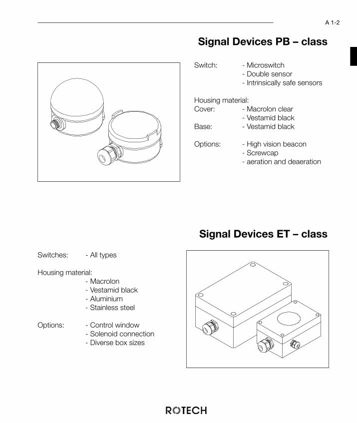
Signal Devices PB – class
Switch: - Microswitch- Double sensor- Intrinsically safe sensors
Housing material:Cover: - Macrolon clear
- Vestamid blackBase: - Vestamid black
Options: - High vision beacon- Screwcap- aeration and deaeration
Signal Devices ET – class
Switches: - All types
Housing material:- Macrolon- Vestamid black- Aluminium- Stainless steel
Options: - Control window- Solenoid connection- Diverse box sizes

Signal Devices TCR – class
The TCR-series is designed in close co-opera-tion with the experience and the needs of theusers. As a result this exceptional design has anumber of outstanding technical features thatoffer many advantages compared to well-kno-wn technology.
Great effort was expended in the compactconstruction, nevertheless there is enoughspace to mount 4 mechanical switches, 4slotted proximitiy switches or 2 proximitiy sen-sors (max. M18 x 65mm)
A2-1
The consideration of the VDI/VDE 3845 interface in the body is unique. All switching compo-nents for open construction (for example the UNI-sandwich system) can be used with the hou-sing.The base provides the possibility to mount a brass filter element to have the same pressure in-side and outside the housing. Therefore water condensation is almost impossible. Another remarkable advantage of the TCR-series is that the cable gland is placed below thebase, where it is protected against impacts. In addition water cannot penetrate through the ca-ble gland as it is always covered by the housing or the actuator.The easy accessible position of the terminals offers the easiest and quickest wiring when brin-ging the modul into operation.Integrated into the base is now the possibility to directly connect a solenoid valve. This enablesthe user to control the actuator and poll the end positions using only one cable.
TCR-HOUSING

A 2-2
The cover serves as a protection for the enclosed switching devices and has to resist the sur-rounding conditions. To fullfill all application requirements TCR- covers can be manufacturedout of different materials.
Every box of the TCR-series can be upgra-ded with a high vision beacon. This allows vi-sual control of the valve position from almostevery direction. Available in various colorcombinations.
For operation in factories the transparent macrolon cover is very suitable, especially on serviceduty.For outdoor areas with high static loads the black vestamid cover is highly suitable. This coveris resistant against higher temperatures and ultra-violet lights and has a extremely low electricalresistance.
High vision beacon

Mechanically operated Signal Devices TCR- series
Manufacturer: Crouzet CrouzetType: 83 161 301 83 161 801Switches loads : 16 A, 250 V ~ 0,1 A, 250 V ~
acc. to UL + CSAContacts: Silver-nickel gold alloyMechanical life: 2 x 10⁷ 5 x 10⁷
Ingress protection: IP 65 IP 65acc. to IEC 529 / DIN 40 050
Temp. range: -20 ... +100 °C -25 ... +85 °CSwitching precision
of the unit: 1,5° 1,5°Base: Vestamid blackCover: Makrolon clear, Vestamid black
or Aluminium nickel platedSealing (housing): EPDM, NBR or SiliconProv. connection: M20 x 1,5solenoid connection: M12 x 1,5
The TCR- module with microswitches con-verts the end positions or middle position ofthe actuator into electrical signals.The microswitch in the body is commonlyused in cases where there are no special re-quirements or the working voltage should beset free.The microswitch with its compact design isvery suitable for mounting into the housing.When used as a potential free contact, theswitch provides a very wide range of control-ling possibilities.The fully adjustable serrated cams are lockedtogether to ensure that the adjusted setting issecured against vibration.Also available with high vision beacon.
ADVANTAGES
• „Open“ and „Closed“ position is easilyadjusted by the switch cams.
• easy mounting by using screws with al-most all components
• terminal block to connect solenoid valves
Microswitches
closed Zu
fermé
open Auf
ouvert
MV
1
2
3
4
5
6
7
8PE
A 2-3
TECHNICAL DATA
WIRING DIAGRAMMicroswitch

Pos. Pcs. Description Material1 1 Housing (base) Vestamid
2 1 O-ring sealing optional
3 1 Internal cover PA + 30%GF
4 1 Housing (cover) optional
5 1 TCR- axis POM
6 1 Switch cam system POM, A2
7 2 Microswitch -
8 1 Terminal block, 7 poles -
9 1 Cable gland -
10 1 Dummy plug for solenoid con. -
11 1 Bracket, size 1-4 A2 or PA
A 2-4
123
75
64
8
12
34
56
778
7464
146
T CR 3 M V S AZ
Display: A = OpenM = MiddleZ = Closed
Vision beacon: S (optional)
Base: V = Vestamid
Cover: M = MacrolonA = AluminiumV = Vestamid
Type : 3 = 83.161.3018 = 83.161.801
Make: Crouzet
Module: T = TCR
Ordering informationTCR-modul with microswitches (without bracket)
1
11
9
87
6
5
4
3
2
10Brackets chapter A5

A 2-5
WIRING DIAGRAM3-wire, PNP
Contact Free Operated Signal Device TCR-Line
The TCR-module with a slotted sensor convertsthe end positions or middle positions of the ac-tuator into electrical signals.Using double sensors supports an easy con-struction of the unit.Switches of various manufacturers can be usedin the TCR-housing, thus being protected fromdirt and mechanical damage.The fully adjustable serrated cams are locked to-gether to ensure that the adjusted setting is se-cured against any vibration.
ADVANTAGES
• very cost friendly and easy to servicedue to its construction principle
• adjustment of the switching points inthe range from 0° to 360°
TECHNICAL DATA
3-wire-doublesensor in TCR-housing
BU
WH
BK
BN
1
2
L -L +
1
2
3
4
5
6
7
A1
A2
closed Zu
fermé
open Auf
ouvert
MV
PE
+-
Manufacturer: IFM Pepperl + Fuchs TurckType: IN 5251 NBN3-F25-E8 Ni4-DS20-
2AP6X2double sensor inductive, 3-wire, NO, DC PNP
Switch distance: 4 mm 3 mm 4 mmNom. voltage: 10 ... 36 V DC 10 ... 30 V DC 10 ... 30 V DCOutput: short-circuit proof, r everse polarity proofTemp. range: -25 ... +80 °C -25 ... +70 °C -25 ... +70 °CProtection class: IP 67 for sensor, IP 65 for housingSwitch accuracy ≤ 0,5° ≤ 0,5° ≤ 0,5°tBase (housing): Vestamid blackCover (housing): optionalSealing: EPDM, NBR or SiliconSystem connection: M20 x 1,5Solenoid connection: M12 x 1,5
A 2-6
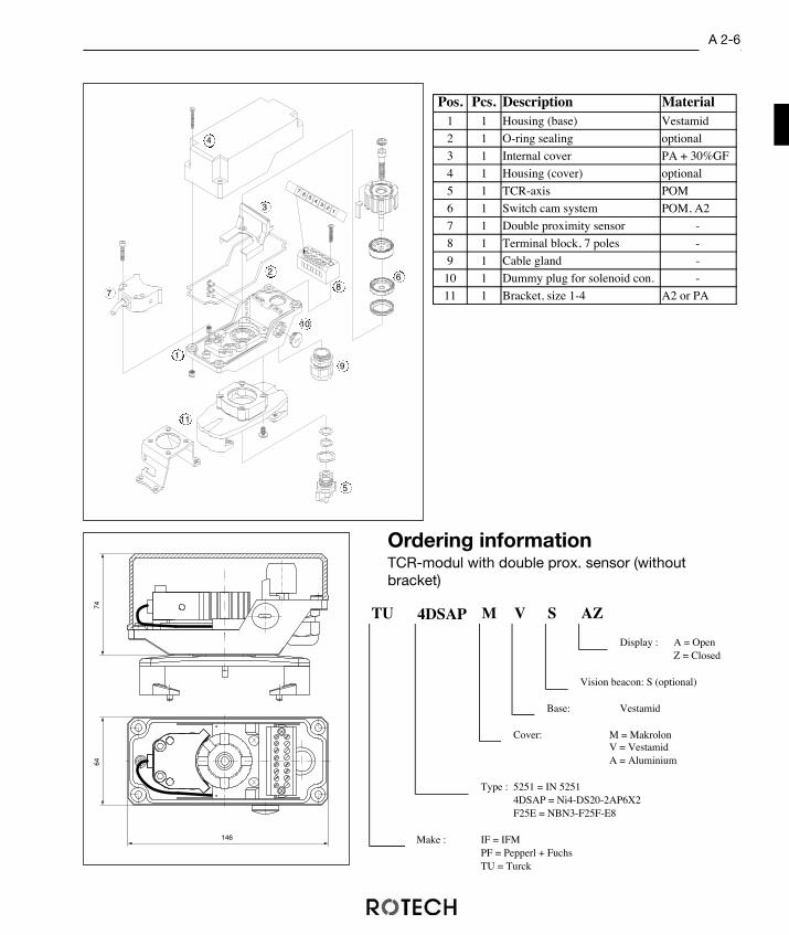
Pos. Pcs. Description Material1 1 Housing (base) Vestamid
2 1 O-ring sealing optional
3 1 Internal cover PA + 30%GF
4 1 Housing (cover) optional
5 1 TCR-axis POM
6 1 Switch cam system POM, A2
7 1 Double proximity sensor -
8 1 Terminal block, 7 poles -
9 1 Cable gland -
10 1 Dummy plug for solenoid con. -
11 1 Bracket, size 1-4 A2 or PA
123
75
64
12
34
56
7
Ordering informationTCR-modul with double prox. sensor (withoutbracket)
TU M V S AZ
Z = Closed
Make :
TU = Turck
4DSAP = Ni4-DS20-2AP6X2F25E = NBN3-F25F-E8
IF = IFMPF = Pepperl + Fuchs
V = VestamidA = Aluminium
Type : 5251 = IN 5251
Base: Vestamid
Cover: M = Makrolon
4DSAP
Display : A = Open
Vision beacon: S (optional)
74
64
146
1
11
9
87
6
5
4
3
2
10

TECHNICAL DATA
Manufacturer: Pepperl + FuchsType: NBN 4-12 GM50 - E2
inductive, 3-wire, NO DC PNPSwitch distance: 4 mmNom. voltage: 10 - 30 V DCContinous current: 100 mANeutral current: ≤ 15 mAOutput: short-circuit proof, r everse polarity proof
damped ≤ 0.3 V, undamped ≥ Us - 3 VDisplay: LED, yellowBase: Vestamid blackCover: optional Makrolon clear, Vestamid
black or Aluminium nickel platedSealing: EPDM, NBR or siliconIngress protection: sensor: IP 67, housing: IP 65
acc. to IEC 529 / DIN 40 050Switching precision
of the unit: ≤ 0.5°Temp. range: - 25 to + 70 °CProv. connection: M20 x 1.5solenoid connection: M12 x 1.5
Contact Free Operated Signal Devices TCR-Line
The TCR-module with 3-wire proximity sensorconverts the end positions or middle positions ofthe actuator into electrical signals.The 3-wire sensor is often used in Europeancountries as a contact free operated signal devicefor non-hazardous applications.The 3-wire sensor is considered very reliable in itsswitching features because of its low residual vol-tage and the low potential difference in the swit-ched state.The design and the dimensions of the TCR-hou-sing allows it to mount sensors with a length upto65 mm. Unique is the adjustment of every sensorin the range of 0° to 360°. The fully adjustable ser-rated cams are locked together to ensure that theadjusted setting is secured against any vibration.
• Easy and exact adjustment of theswitching points in the range from 0°to 360°,
• sensors are mountable up to the sizeof M18 x 65 mm.
3-Wire Proximity Sensor
ADVANTAGES
A 2-7
BU
BK
1
closed Zu
fermé
open Auf
ouvert
2
3
4
5
6
7
BN
BK
MV
L+ L-
A1
A2
PE
+ -
WIRING DIAGRAM3-wire, PNP

12
3
75
64
12
34
56
7
9
Pos. Pcs. Description Material1 1 Housing (base) Vestamid
2 1 O-ring sealing optional
3 1 Internal cover PA + 30%GF
4 1 Housing (cover) optional
5 1 TCR-axis POM
6 1 Switch cam system POM
7 2 Proximity sensor -
8 1 Sensor plate PA + 30%GF
9 1 Dampening flag PE chrom plated
10 1 Terminal block, 7 poles -
11 1 Cable gland -
12 1 Dummy plug for solenoid con. -
13 1 Bracket, size 1-4 A2 or PA
Ordering informationTCR-Modul with proximity sensor (without bracket)
A 2-8
T PF N412E M V S AZ
Display : A = OpenZ = Closed
Vision beacon : S (optional)
Base : V = Vestamid
Cover : M = MakrolonA = AluminiumV = Vestamid
Type : NBN 4-12 GM50-E2
Make : Pepperl + Fuchs
Type : T = TCR
74
146
64
1
12
13
11
8
7 6
5
4
3
2
10
Brackets chapter A5
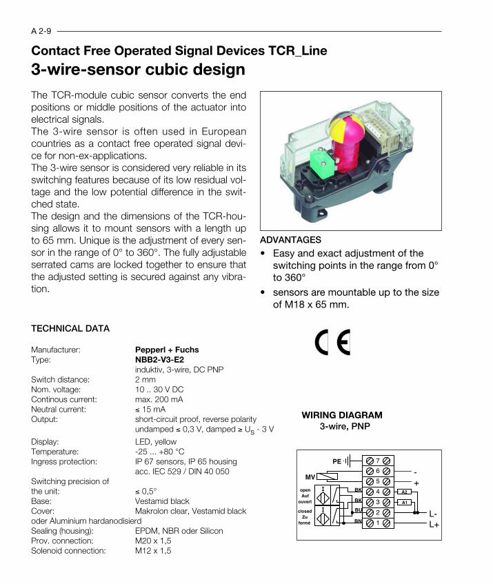
Contact Free Operated Signal Devices TCR_Line
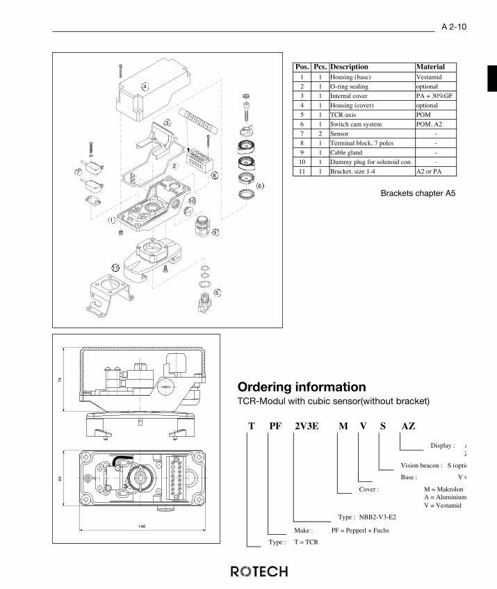
The TCR-module cubic sensor converts the endpositions or middle positions of the actuator intoelectrical signals.The 3-wire sensor is often used in Europeancountries as a contact free operated signal devi-ce for non-ex-applications.The 3-wire sensor is considered very reliable in itsswitching features because of its low residual vol-tage and the low potential difference in the swit-ched state.The design and the dimensions of the TCR-hou-sing allows it to mount sensors with a length upto 65 mm. Unique is the adjustment of every sen-sor in the range of 0° to 360°. The fully adjustableserrated cams are locked together to ensure thatthe adjusted setting is secured against any vibra-tion.
Manufacturer: Pepperl + FuchsType: NBB2-V3-E2
induktiv, 3-wire, DC PNPSwitch distance: 2 mmNom. voltage: 10 .. 30 V DCContinous current: max. 200 mANeutral current: ≤ 15 mAOutput: short-circuit proof, reverse polarity
undamped ≤ 0,3 V, damped ≥ Us - 3 V
Display: LED, yellowTemperature: -25 ... +80 °CIngress protection: IP 67 sensors, IP 65 housing
acc. IEC 529 / DIN 40 050Switching precision of the unit: ≤ 0,5°Base: Vestamid blackCover: Makrolon clear, Vestamid blackoder Aluminium hardanodisierdSealing (housing): EPDM, NBR oder SiliconProv. connection: M20 x 1,5Solenoid connection: M12 x 1,5
3-wire-sensor cubic design
ADVANTAGES
A 2-9
BU
BK
1
closed Zu
fermé
open Auf
ouvert
2
3
4
5
6
7
BN
BK
MV
L+ L-
A1
A2
PE
+ -
• Easy and exact adjustment of theswitching points in the range from 0°to 360°
• sensors are mountable up to the sizeof M18 x 65 mm.
TECHNICAL DATA
WIRING DIAGRAM3-wire, PNP
A 2-10
T PF 2V3E M V S AZ
Display : AZ
Vision beacon : S (optio
Base : V =
Cover : M = MakrolonA = AluminiumV = Vestamid
Type : NBB2-V3-E2
Make : PF = Pepperl + Fuchs
Type : T = TCR
Ordering informationTCR-Modul with cubic sensor(without bracket)
Pos. Pcs. Description Material1 1 Housing (base) Vestamid
2 1 O-ring sealing optional
3 1 Internal cover PA + 30%GF
4 1 Housing (cover) optional
5 1 TCR-axis POM
6 1 Switch cam system POM, A2
7 2 Sensor -
8 1 Terminal block, 7 poles -
9 1 Cable gland -
10 1 Dummy plug for solenoid con. -
11 1 Bracket, size 1-4 A2 or PA
7464
146
12
34
56
7
12
3
75
64
1
11
9
87
6
5
4
3
2
10Brackets chapter A5

Contact Free Operated Signal Devices TCR-Line
The TCR-module with a slotted sensor convertsthe end positions or middle positions of the ac-tuator into electrical signals.The slotted sensor is commonly used in the che-mical industry and generally in applications withexplosion protection, although 2-wire technologyis also increasingly applied in mechanical en-gineering.The slotted proximity sensor is intrinsically safebecause of the low potential. There is no need ofan additional explosion protection installation.The fully adjustable serrated cams are locked to-gether to ensure that the adjusted setting is se-cured against any vibration.
ADVANTAGES
Manufaturer: Pepperl + Fuchs Pepperl + FuchsType: SJ 3,5 N SJ 5 N
slotted sensor, NC, NAMUR (DIN 19 234)Nom. voltage: 8 V DC 8 V DCWorking voltage: 5 .. 25 V DC 5 .. 25 V DCOutput: short-circuit proof
undamped ≥ 3 mA, damped ≤ 1 mABase: Vestamid blackCover: optional Makrolon clear, Vestamid black or
Aluminium nickel platedSealing: EPDM, NBR or siliconIngress protection: sensor: IP 67, housing: IP 65
acc. to IEC 529 / DIN 40 050Switching precision
of the unit: ≤ 0.5°Temp. range: - 25 to + 85 °C - 25 to + 85 °CProv. connection: M20x1,5solenoid connection: M12x1,5
• The end position can damped or un-damped,
• high switching precision by a large dia-meter of the disc
• up to 4 slotted proximity sensors can bemounted.
TECHNICAL DATA
EEx i - Slotted Proximity Sensor
A 2-11
WIRING DIAGRAM
41
42
51
52
BU
BNclosed
Zu fermé
BU
BN
open Auf
ouvert
+ - + -
GW 2
GW 1

Ordering informationTCR-Modul with slotted sensor (without bracket)
A 2-12
T PF 3 N M S V AZ
Anzeige : A = AufM = MitteZ = Zu
Sockelwerkstoff : V = Vestamid
Sichtanzeige : S (optional)
Deckelwerkstoff : M = MakrolonA = AluminiumV = Vestamid
Typ : N = ... - NS = ... - SN
Schlitzgröße : 3 = 3,5mm5 = 5mm
Fabrikat : PF = Pepperl + Fuchs
TU = Turck
Bauart: T = TCR
Pos. Pcs. Description Material1 1 Housing (base) Vestamid
2 1 O-ring sealing optional
3 1 Internal cover PA + 30%GF
4 1 Housing (cover) optional
5 1 TCR-axis POM
6 1 Switch cam system POM
7 2 Slotted proximity sensor -
8 1 Sensor plate PA + 30%GF
9 2 Dampening flag A2
10 1 Terminal block, 4 poles -
11 1 Cable gland -
12 1 Dummy plug for solenoid con. -
13 1 Bracket, Size 1-4 A2 or PA
GW2GW2
GW1
GW1
GW1
GW2
GW1
GW2
74
64
146
1
13
12
11
9
9
8
7
6
5
4
3
210
Brackets chapter A5

A 2-13
WIRING DIAGRAM2-wire, NAMUR
Contact Free Operated Signal Devices TCR-Line
The TCR-module with a double sensor convertsthe end positions or middle positions of the ac-tuator into electrical signals. Using double sen-sors supports easy construction of the unit. The 2-wire sensors is commonly used in thechemical industry and generally in applicationswith esplosion protection. The slotted proximity sensor is intrinsically safebecause of the low potential. There is no need ofan additional expolsion protection installation.The fully adjustable serrated cams are locked to-gehther to ensure that the adjusted setting is se-cured against any vibration.Also available with high vision beacon.
ADVANTAGES
• very cost friendly and easy to servicedue to its construction principle
• adjustment of the switching points inthe range from 0° to 360°
TECHNICAL DATA
EEx i - Double Sensor in TCR-housing
Manufacturer: Pepperl + FuchsType: NCN3-F25F-N4
Doublesensor, NAMUR (DIN 19 234)Rated voltage: 8 V DCNom. voltage: 5 .. 25 V DC 5 .. 25 V DCOutput: short circuit proof
undamped ≥ 3 mA, damped ≤ 1 mATemperature: -25 ... +85 °CProtection class: IP 67 for Sensor, IP 65 for housing
acc. IEC 529 / DIN 40 050Switching precision of the unit: ≤ 0,5°Base: Vestamid blackCover: Makrolon transparent, Vestamid black or Aluminium Sealing (housing): EPDM, NBR or SiliconSystem connection: M20 x 1,5Solenoid connection: M12 x 1,5 1
2
3
4
5
6
7
MV
PE
closed Zu
fermé
open Auf
ouvert
+-+-+-
2
1
BK
BU
WH
BN
EEx i

Pos. Pcs. Description Material1 1 Housing (base) Vestamid
2 1 O-ring sealing optional
3 1 Internal cover PA + 30%GF
4 1 Housing (cover9 optional
5 1 TCR-axis POM
6 1 Switch cam system POM, A2
7 1 Doublesensor NAMUR -
8 1 Terminal block, 7 poles -
9 1 Cable gland -
10 1 Dummy plug for solenoid con. -
11 1 Bracket, size 1-4 A2 or PA123
75
64
12
34
56
7
A 2-14
Ordering informationTCR-Modul with double sensor (without bracket)
T PF F25N M V S AZ
Display :A = OpenZ = Closed
Vision beacon: S (optional)
Base: Vestamid
Cover: M = MakrolonV = VestamidA = Aluminium
Type: F25N = NCN3-F25F-N4
Make: PF =Pepperl + Fuchs
Type: T = TCR
74
64
146
NB
N3-
F25
F-N
4
III
1
11
9
87
6
5
4
3
2
10
Brackets chapter A5

EEx ed IIC T6 – Limit Switch Box
Signal Devices In TCR-Housing for Ex-Areas
The limit switch module for hazardous areasconverts mechanical end or middle positionsof the actuator into electrical signals.The microswitch (EEx d IIC T6) is through itsvery compact design especially suited to bemounted into a housing. As a potential freeswitch over contact it is flexible in the kind ofcontrol.The TCR-module made of a shock-proof Ve-stamid housing is certified for protectionclass EEx ed IIC T6 by using componentsthat are increased safety and flame proof.The fully adjustable serrated cams are lockedtogether to ensure that the adjusted settingis secured against any vibration.
ADVANTAGES
Manufacturer: CrouzetType: 83 139 1Ingress protection of the: EEx d IIC T6
switch acc. to EN 50014Switched power: 5 A, 250 V ~
acc. to UL + CSAContacts: silver-nickel
Mechanical life: 5 x 10⁶ operationsSealing (housing): EPDM 60 Shore AIngress protection: housing: IP 65, switch: IP 67
acc. to IEC 529 / DIN 40 050Switching precision
of the unit: = 1.5°Cable gland: M20 x 1.5 (EEx e II)Temp. range: - 20 to + 60°CHousing material: Vestamid black
• protection class EEx ed IIC T6• display ”Open” and ”Closed” can be
adjusted individually by the switch cams
• very good price / performance ratio
A 2-15
WIRING DIAGRAM
BN
WH
BK
1
2
3
4
5
6
closed Zu
fermé
open Auf
ouvert
12
34
12
34
BU
BN
WH
BK
BU
TECHNICAL DATA

Ordering informationTCR-modul EEx ed IIC T6 (without bracket)
A 2-16
Pos. Pcs. Description Material1 1 Housing (base) Vestamid
2 1 O-ring sealing EPDM 60
3 1 Internal cover PA + 30%GF
4 1 Housing (cover) Vestamid
5 1 TCR-axis POM
6 1 Switch cam system POM
7 2 Microswitch EEx d IIC T6 -
8 1 Terminal block, 6 poles -
EEx e II
9 1 Cable gland -
EEx e II
10 1 Bracket, Size 1-4 A2 oder PA
T CR 1 V V AZ
Display : A = OpenM = MiddleZ = Closed
Base : V = Vestamid
Cover : V = VestamidA = Aluminium
Type : 1 = 83.139.1EEx d IIC T6
Make : Crouzet
Type : T = TCR
74
64
146
1
9
8
7
6
5
4
3
2
10
Brackets chapter A5

Zentral-einheit
Actuator – Sensor – Interface
A 2-17
The actuator-sensor-interface is a new net system forbinary sensors and actuators of the lowest field bus level.The process signals are commonly transmitted to thecontrol system by a complex parallel wiring. The AS-inter-face replaces the complex wiring with an easy 2-wireconnection, common to all sensors and actuators.The AS-interface is an open standard, independent of anymanufacturer. The advantage for the user is that differentAS-interfaces can be applied. Functionally similar devicesof different manufacturers can be exchanged easily.The AS-interface works according to the master-slave-principle. Every slave connected by the AS-interface cancontrol four binary elements that can act as inputs (sen-sor) or outputs (actuator). A fully equipped master with 30+ 1 slaves can control 124 binary elements.
By using the new bi-directional sla-ves the max. possible number ofbinary sensors or actuators is 248. Another important advantage of theAS-interface techinque is the use ofone wire for data transmission andpower supply to the slaves.The connection is easily done by pe-netration terminals.
Characteristics
Topology: optional: linear, star, tree, ring
Number of nodes: 31 ASI-slaves / 1 master
Addressing: By master with programming
unit or automatically by node
replacement
Cabeling: Unscreened 1.5 mm2
Expansion: 100 m total length (without
repeater)
Transmission rate: Approx. 167 kBit/s
Bit coding: Manchester code
Cycle time: 5 ms for 31 slaves
Data per message: 4 bit bi-directional
Error detection: 1 parity bit + signal quality
monitoring
Steuerungen
System-gruppen
Sensoren + Aktoren

AS-interface masterThe master monitors the AS-Interface sy-stem and organises the data exchangewith its slaves. The master acts as a slaveto the higher level fieldbus such as PRO-FIBUS, INTERBUS-S, MODBUS or othersimilar systems.The model as a stand alone master canstore commands and is capable of calcu-lating combinations of inputs and outputson its own.
AS-interface power supplyFor supplying the ASI network a special power supply is required. A standard 24V powersupply cannot be used as it must also control the de-coupling of the data signal from thesupply voltage.
AS-interface modulesPreviously installed standard sensors or actuators in 2-wire or 3-wire configurations can beconnected by modules into the AS-interface net. Every group represents only one partici-pant in the system, so that 248 binary elements can be combined with the net.
AS-interface sensors/actuatorsSensors with an integral ASI chip offer you enormous advantages. They can be controlleddirectly from the bus, and be connected directly to the serial data line.
AS-interface limit switch boxThe special I/O-module of the ROTECH limit switch box records the actuator position ”open/ closed” and at the same time controls the magnetic valve solenoid of the pneumatic ac-tuator. The complete module represents a single participant in the AS-Interface net.
AS-interface conduitIn addition to standard round cable, special ASI ribbon cable has come into its own for net-working, enabling easy component linking using the penetration technique.
The AS-interface system components
A 2-18
Feldbussystem
AS-InterfaceMaster
Anderwendersystem(SPS, PC, ... )
AS-InterfaceNetzteil
Endschalterkasten

Intelligent Signal Devices TCR-Line
The AS-interface module converts the mecha-nical end or middle positions of the pneumaticactuator into electrical signals and transmitsthem by the AS-interface bus system. This canbe realized with Namur-switches or goldcontact micro-switches.The TCR-module also allows indirect control ofa magnetic valve solenoid (2.6W/24V) via thebus.The connection with the special penetrationtechnique allows the mounting of the moduleat any position on an existing or new AS-inter-face cable without using special tools.The box is available with high vision beacon,too.
ADVANTAGES
Manufacturer: alternativType: Sensors acc. NAMUR (DIN 19 234)
Microswitch with gold alloyOutput AS-Interface (1 Slaveadress)
Bit 0 Magnetic valve solenoid controlBit 2 Sensor 1Bit 3 Sensor 2
Nom. voltage: 30 V DC (AS-interface power supply)Temperature: -25 ... +85 °CBase: Vestamid blackCover: Makrolon clear, Vestamid
black or Aluminium nickel platedSealing: EPDM, NBR or SiliconSchutzart: IP 67 for Sensor, Housing IP 65
acc. IEC 529 / DIN 40 050Connection: AS-Interface
• Bus connection of the complete limitswitch module
• integrated control of a magnetic valvesolenoid
• easy and quick mounting and wiring.
TECHNICAL DATA
AS – Interface
A 2-19
WIRING DIAGRAM
BU
BNclosed
Zu fermé
BU
BN
open Auf
ouvert
+ -
ASI2,6 W / 24 V
ASI
MV
closed Zu
fermé
open Auf
ouvert
+ -
ASI2,6 W / 24 V
ASI
MV

Ordering informationTCR-Modul with AS-Interface (without bracket)
A 2-20
T PF 3N M V S AZ
Display : A = OpenZ = Closed
High Vision Beacon : S (optional)
Base : V = Vestamid
Cover : M = MakrolonA = AluminiumV = Vestamid
Type : 3N = SJ3,5 N5N = SJ5 NF25N = NCN3-F25F-N48 = 83 161 801
Make : PF = Pepperl + Fuchs
CR = Crouzet
Type : T = TCR
STKASI
wired by an AS-Interface-connection module
Pos. Pcs. Description Material1 1 Housing (base) Vestamid
2 1 O-ring sealing EPDM 60
3 1 Internal cover PA + 30%GF
4 1 Housing (cover) optional
5 1 TCR-axis POM
6 1 Switch cam system POM, A2
7 2 Slotted prox. sensor NAMUR -
8 1 Slotted prox. sensor NAMUR -
Aktor-Sensor-Interface
9 1 Control unit -
Actuator-Sensor-Interface
10 1 Dummy plug for solenoid con. -
11 1 Bracket, size 1-4 A2 oder PA
74
64
146
1
11
9
8
7
6
5
4
3
2
10
Brackets chapter A5

Solenoid valve
In many areas of industrial engineering pneu-matic actuators are used to control valves.The TCR-housing offers the possibility toconnect the control solenoid with the limitswitch unit.Through a cable gland at the side of the hou-sing the solenoid is wired onto the mutualterminal block. The whole unit can thereforebe wired to the control sys- tem with justone cable.
Forspeci-al ap-
plications it maybe useful to have the possi-bility to disconnect the solenoid and the limitswitch unit. For this kind of requirement theTCR-housing can be equipped with a pluga-ble connection. The cable gland is wired tothe terminal block inside the box.
A 2-21
Connectivity Options
Solenoid valve
Solenoid valve
TCR3MVAZ M12
M12 = M12 x 1,5 KabelverschraubungLU = Lumberg RKF 5
Signal device
Ordering informationbox with solenoid connection

Ordering informationBox with plug connector
More plug connections upon request
Plug connection
The TCR-housing has another advantagethat makes maintainance much easier.The design of the housing enables plug-in connectors to be used for linking to thecontrol system. The part of the housing that juts out pro-tects the plug from mechanical damage.
A 2-22
TECHNICAL DATA :Manufacturer: Amphenol TuchelType: C 16-1Housing: Polyamid 6.6
self extinguishingIngress protection: IP 66
acc. to IEC 529 / DIN 40 050Number of contacts: 6 + PEContacts: silverLock: screwedmax. Current: 10 A at 45°CVoltages: 250 V AC
300 V DCCable diameter: 9.5 ... 13 mmTemperature range: -40 to +100 °C
TECHNICAL DATA :Manufacturer: Harting HartingType: Han 7 D Han 8 UHousing: Thermoplast pressed cast alloyIngress protection: IP 65 IP 65
acc. to IEC 529 / DIN 40 050Number of contacts: 7 + PE 8Contacts: hard silver hard silver
hard goldLock: screwedmax. Current: 10 A Voltages: 250 V AC 42 V AC
300 V DC 50 V DCCable gland: PG 11 PG 11 Temperature range: -40 to +125 °C -40 to +125 °C
TCR3MVAZ AMP
AMP = Amphenol TuchelHA7 = Harting Han 7 DHA8 = Harting Han 8 U
Signal device
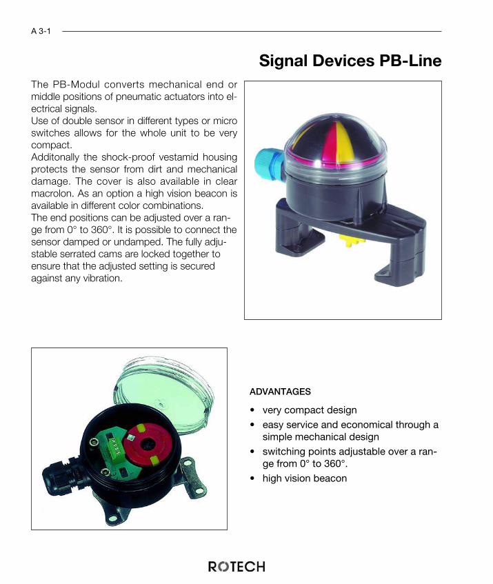
The PB-Modul converts mechanical end ormiddle positions of pneumatic actuators into el-ectrical signals.Use of double sensor in different types or microswitches allows for the whole unit to be verycompact.Additonally the shock-proof vestamid housingprotects the sensor from dirt and mechanicaldamage. The cover is also available in clearmacrolon. As an option a high vision beacon isavailable in different color combinations.The end positions can be adjusted over a ran-ge from 0° to 360°. It is possible to connect thesensor damped or undamped. The fully adju-stable serrated cams are locked together toensure that the adjusted setting is securedagainst any vibration.
ADVANTAGES
• very compact design
• easy service and economical through asimple mechanical design
• switching points adjustable over a ran-ge from 0° to 360°.
• high vision beacon
Signal Devices PB-Line
A 3-1
ADVANTAGES
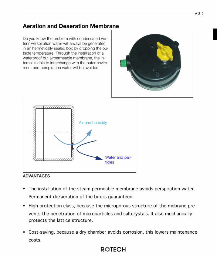
Aeration and Deaeration Membrane
A 3-2
• The installation of the steam permeable membrane avoids perspiration water.
Permanent de/aeration of the box is guaranteed.
• High protection class, because the microporous structure of the mebrane pre-
vents the penetration of microparticles and saltcrystals. It also mechanicallyprotects the lattice structure.
• Cost-saving, because a dry chamber avoids corrosion, this lowers maintenance
costs.
Do you know the problem with condensated wa-ter? Perspiration water will always be generatedin an hermetically sealed box by dropping the ou-tside temperature. Through the installation of awaterproof but airpermeable membrane, the in-ternal is able to interchange with the outer enviro-ment and perspiration water will be avoided.
Air and humidity
Water and par-ticles

Mechanically Operated Signal Devices PB-Line
ADVANTAGES
Manufacturer: Crouzet CrouzetType: 83 161 301 83 161 801Switched loads 16 A, 250 V ~ 0.1 A, 250 V ~
acc. to UL + CSAContacts: silver-nickel gold alloy
Mechanical life: 2 x 10⁷ 5 x 10⁷
Sealing (Housing): EPDM, NBR or siliconIngress protection: IP 65 IP 65
acc. to IEC 529 / DIN 40 050Switching precision
of the unit: 1.5° 1.5°Base: Vestamid blackCover: Makrolon clear, Vestamid black
or high vision beaconSealing (Housing): EPDM, NBR or SiliconConnection: Pluggable cable connection and
cable gland M20x1,5
• very compact design
• wide range of use
• switching points adjustable over a ran-ge from 0° to 360°
TECHNICAL DATA
Microswitch
A 3-3
The PB-module with microswitches convertsthe mechanical end or middle positions of theactuator into electrical signals.Microswitches are mainly used where thereare no special requirements or the workingvoltage should be set freely. Being a potential-free contact the switch provides a wide rangeof controlling possibilities.The end positions can be adjusted over a ran-ge from 0° to 360°. It is possible to connectthe sensor damped or undamped. The fullyadjustable serrated cams are locked togetherto ensure that the adjusted setting is securedagainst any vibration.
WIRING DIAGRAM
closed Zu
fermé
open Auf
ouvert
1
2
3
4
5

5080
Ordering informationPB-Modul with microswitch (without bracket)
A 3-4
Pos. Pcs. Description Material1 1 Housing (base) Vestamid2 1 O-ring sealing optional3 1 Housing (cover9 optional4 1 TCR-axis POM5 1 Switch cam system POM, A26 1 Cable gland ---7 2 Microswitch ---8 1 Terminal block, 5 poles ---9 1 Bracket, size 1-4 A2 or PA
P CR 3 M V AZ
Display : A = OpenZ = Closed
Cover : V = Vestamid
Base : M = MakrolonV = VestamidS = High vision beacon
Type : 3 = 83.161.301
8 = 83.161.801
Make : CR = Crouzet
Type : P = proxi-box
1
7
9
8
6
5
4
3
2
Brackets chapter A5

WIRING DIAGRAM3-wire, PNP
Contact Free Operated Signal Device Proxi-Box
ADVANTAGES
Manufacturer: Pepperl + FuchsType: NBN3-F25F-E8-P
Doublesenor NODC PNP
Switch distance: 3 mmWorking voltage: 10 ... 30 V DCOutput: short-circuit proof
reverse polarity prot.Temperature: -25 ... +70 °CBase: Vestamid blackCover: Makrolon clear, Vestamid black or high vision beaconSealing: EPDM, NBR or SiliconIngress protection: IP 67 for sensor, IP 65 for housing
acc. IEC 529 / DIN 40 050Switching precision ≤ 0,5° ≤ 0,5°
of the unit:Connection: Pluggable cable connection and cable
gland M20x1,5
• very compact design
• easy service and economical through asimple mechanical design
• available with high vision beacon
TECHNICAL DATA:
3-wire Doublesensor with terminal block
A 3-5
1
2
L -
L +
A1
A2
closed Zu
fermé
open Auf
ouvert
4
2
3
1
The PB-module with double proximity sen-sor converts the mechanical end or middlepositions of the actuator into electrical sig-nals.A plugable terminal block is integrated intothe sensor. This makes maintening and wi-ring of the box easier.The end positions can be adjusted over arange from 0° to 360°. It is possible toconnect the sensor damped or undamped.The fully adjustable serrated cams arelocked together to ensure that the adjustedsetting is secured against any vibration.
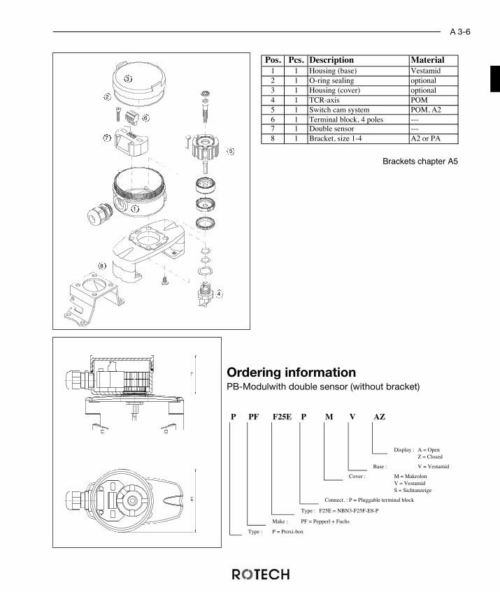
Ordering informationPB-Modulwith double sensor (without bracket)
A 3-6
P PF F25E P M V AZ
Display : A = OpenZ = Closed
Base : V = Vestamid
Cover : M = MakrolonV = VestamidS = Sichtanzeige
Connect. : P = Pluggable terminal block
Type : F25E = NBN3-F25F-E8-P
Make : PF = Pepperl + Fuchs
Type : P = Proxi-box
Pos. Pcs. Description Material1 1 Housing (base) Vestamid2 1 O-ring sealing optional3 1 Housing (cover) optional4 1 TCR-axis POM5 1 Switch cam system POM, A26 1 Terminal block, 4 poles ---7 1 Double sensor ---8 1 Bracket, size 1-4 A2 or PA
5080
1
7
8
6
5
4
3
2
Brackets chapter A5

WIRING DIAGRAM3-wire, PNP
Manufacturer: Pepperl + Fuchs Pepperl + FuchsType: NBN3-F25F-E8 NCN3-F25F-E8-V1
Doublesensor NODC PNP
Connection: Cable 5 m M12-plug connector
Switch distance: 3 mmWorking voltage: 10 ... 30 V DCOutput: short-circuit proof,
reverse polarity prot.Temperature: -25 ... +70 °CBase: Vestamid blackCover: Makrolon clear, Vestamid black
or high vision beaconSealing: EPDM, NBR or SiliconIngress protection: IP 67 for sensor,
acc. IEC 529 / DIN 40 050 IP 65 for housingSwitching precision: ≤ 0,5°
TECHNICAL DATA
1
2
L -
L +
A1
A2
closed Zu
fermé
open Auf
ouvert
1
2
3
4
1
2
L -
L +
A1
A2
closed Zu
fermé
open Auf
ouvert
BN
BU
WH
BK
Contact Free Operated Signal Device Proxi-Box
3-Wire-Double Sensor With Plug Or CableThe PB-module with double proximity sensorconverts the mechanical end or middle positionsof the actuator into electrical signals.By using double sensors it is possible to have acompact design of unit. The housing made ofshock proof Vestamid provides excellent protec-tion for the sensor against dirt and mechanicaldamage.The end positions can be adjusted over a rangefrom 0° to 360°. It is possible to connect the sen-sor damped or undamped. The fully adjustableserrated cams are locked together to ensure thatthe adjusted setting is secured against any vibra-tion.
ADVANTAGES
• very compact design
• easy service and economical through asimple mechanical design
• available with high vision beacon
A 3-7

Ordering informationPB-Modul with double sensor (without bracket)
A 3-8
P PF F25E S M V AZ
Display : A = OpenZ = Closed
Base : V = Vestamid
Cover : M = MakrolonV = VestamidS = Sichtanzeige
Connect. : K = Cable 5 mS = M12-plug-connector
Type : F25E = NBN3-F25F-E8 (-V1)
Make : PF = Pepperl + Fuchs
Type : P = Proxi-box
Pos. Pcs. Description Material1 1 Housing (base) Vestamid2 1 O-ring sealing optional3 1 Housing (cover9 optional4 1 TCR-axis POM5 1 Switch cam system POM, A26 1 O-ring sealing ---7 1 Double sensor ---8 1 Bracket, size 1-4 A2 or PA
5080
1
7
6
8
5
4
3
2
Brackets chapter A5
L -L +
A1
A2
4
2
3
1
BU
BK
closed Zu
fermé
open Auf
ouvert
BK
BN
WIRING DIAGRAM3-wire, PNP
TECHNICAL DATA
Contact Free Operated Signal Device Proxi-Box
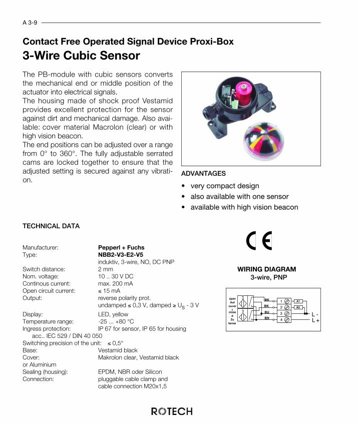
3-Wire Cubic SensorThe PB-module with cubic sensors convertsthe mechanical end or middle position of theactuator into electrical signals. The housing made of shock proof Vestamidprovides excellent protection for the sensoragainst dirt and mechanical damage. Also avai-lable: cover material Macrolon (clear) or withhigh vision beacon.The end positions can be adjusted over a rangefrom 0° to 360°. The fully adjustable serratedcams are locked together to ensure that theadjusted setting is secured against any vibrati-on.
ADVANTAGES
• very compact design
• also available with one sensor
• available with high vision beacon
A 3-9
Manufacturer: Pepperl + FuchsType: NBB2-V3-E2-V5
induktiv, 3-wire, NO, DC PNPSwitch distance: 2 mmNom. voltage: 10 .. 30 V DCContinous current: max. 200 mAOpen circuit current: ≤ 15 mAOutput: reverse polarity prot.
undamped ≤ 0,3 V, damped ≥ Us - 3 V
Display: LED, yellowTemperature range: -25 ... +80 °CIngress protection: IP 67 for sensor, IP 65 for housing
acc.. IEC 529 / DIN 40 050Switching precision of the unit: ≤ 0,5°Base: Vestamid blackCover: Makrolon clear, Vestamid black or AluminiumSealing (housing): EPDM, NBR oder SiliconConnection: pluggable cable clamp and
cable connection M20x1,5

Ordering informationPB-Modul with cubic sensor (without bracket)
A 3-10
P PF 2V3E M V AZ
Display :A = OpenZ = Closed
Base : V = Vestamid
Cover : M = MakrolonV = VestamidS = High vision beacon
Type : 2V3E = NBB2-V3-E2-V5
Make : PF = Pepperl + Fuchs
Type : P = Proxi-box
Pos. Pcs. Description Material1 1 Housing (base) Vestamid2 1 O-ring sealing optional3 1 Housing (cover) optional4 1 TCR-axis POM5 1 Switch cam system, adjustable POM, A26 1 Terminal block, 4 poles ---7 2 Sensor ---8 1 Bracket, size 1-4 A2 or PA
5080
1
7 6
8
5
4
3
2
Brackets chapter A5

WIRING DIAGRAM2-wire, NAMUR
Contact Free Operated Signal Device Proxi-Box
ADVANTAGES
Manufacturer: Pepperl + FuchsType: NCN3-F25F-N4-P
Doublesensor,NC
NAMUR (DIN 19 234)nom. voltage: 8 V DCOutput: short-circuit proof
undamped ≥ 3 mA, damped ≤ 1 mATemperature: -25 ... +85 °CIngress protection: IP 67 for sensor, IP 65 for housing
acc. IEC 529 / DIN 40 050Switching precision : ≤ 0,5°Base: Vestamid blackCover: Makrolon clear, Vestamid black
or with high vision beaconSealing (housing): EPDM, NBR or SiliconConnection: pluggable terminal block and cable gland
M20x1,5
• very compact design
• easy service and economicalthrough a simple mechanicaldesign
• available with high vision beac-on
TECHNICAL DATA
Double Sensor With Terminal PB-Line
A 3-11
2
1
+-+
-3
1
4
2
closed Zu
fermé
open Auf
ouvert
The PB-module with double proximity sensorconverts the mechanical end or middle positionsof the actuator into electrical signals.A pluggable cable clamp is integrated into thesensor. This makes maintening and wiring of thebox easier.The 2-wire sensors is commonly used in thechemical industry and generally in applicationswith esplosion protection. The double sensor is intrinsically safe because ofthe low potential. There is no need of an additio-nal expolsion protection installation. Covers avai-lable: Makrolon clear, Vestamid or high vision be-acon.The fully adjustable serrated cams are locked to-gether to ensure that the adjusted setting is se-cured against any vibration.
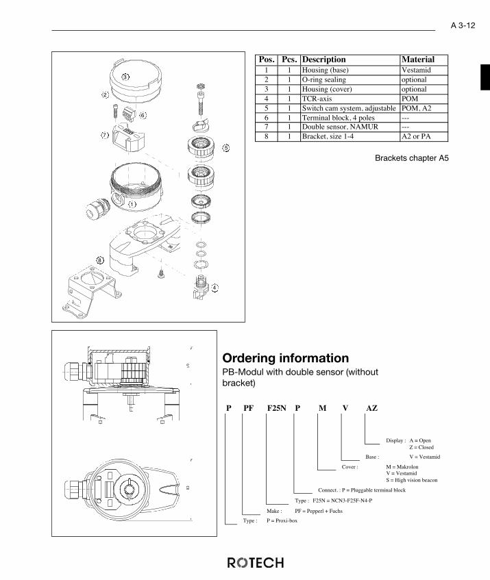
Ordering informationPB-Modul with double sensor (withoutbracket)
A 3-12
P PF F25N P M V AZ
Display : A = OpenZ = Closed
Base : V = Vestamid
Cover : M = MakrolonV = VestamidS = High vision beacon
Connect. : P = Pluggable terminal block
Type : F25N = NCN3-F25F-N4-P
Make : PF = Pepperl + Fuchs
Type : P = Proxi-box
Pos. Pcs. Description Material1 1 Housing (base) Vestamid2 1 O-ring sealing optional3 1 Housing (cover) optional4 1 TCR-axis POM5 1 Switch cam system, adjustable POM, A26 1 Terminal block, 4 poles ---7 1 Double sensor, NAMUR ---8 1 Bracket, size 1-4 A2 or PA
5080
1
7
8
6
5
4
3
2
Brackets chapter A5

WIRING DIAGRAM2-wire, NAMUR
Manufacturer: Pepperl + Fuchs Pepperl + FuchsType: NCN3-F25F-N4 NCN3-F25F-N4-V1
Doublesensor NCNAMUR (DI 19 234)
Connection: Cable 5 m M12-plug
nom. voltage: 8 V DCOutput: short-circuit proof
undamped ≥ 3 mA, damped ≤ 1 mATemperature: -25 ... +85 °CBase: Vestamid blackCover: Makrolon clear, Vestamid black
or high vision beaconSealing: EPDM, NBR or SiliconIngress protection: IP 67 for sensor,
acc. IEC 529 / DIN 40 050 IP 65 for housingSwitching precision: ≤ 0,5°
TECHNICAL DATA
2
1
+-+
-closed
Zu fermé
open Auf
ouvert
1
2
3
4
2
1
+-+
-closed
Zu fermé
open Auf
ouvert
BN
WH
BU
BK
Contact Free Operated Signal Device Proxi-Box
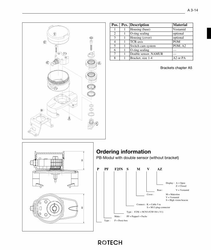
EEx i -Doublesensor with plug or cableThe PB-module with double proximity sensorconverts the mechanical end or middle positi-ons of the actuator into electrical signals. Thesensors are available with M12-plug and cable.The 2-wire sensors is commonly used in thechemical industry and generally in applicationswith esplosion protection. The double sensor is intrinsically safe becauseof the low potential. There is no need of an ad-ditional expolsion protection installation.The end positions can be adjusted over a rangefrom 0° to 360°. It is possible to connect thesensor damped or undamped. The fully adju-stable serrated cams are locked together to en-sure that the adjusted setting is secured againstany vibration.
ADVANTAGES
• very compact design
• various connection possiblities
• switching points adjustable over a ran-ge from 0° to 360°.
A 3-13
Ordering informationPB-Modul with double sensor (without bracket)
A 3-14
P PF F25N S M V AZ
Display : A = OpenZ = Closed
Base : V = Vestamid
Cover : M = MakrolonV = VestamidS = High vision beacon
Connect. : K = Cable 5 mS = M12-plug-connector
Type : F25E = NCN3-F25F-N4 (-V1)
Make : PF = Pepperl + Fuchs
Type : P = Proxi-box
Pos. Pcs. Description Material1 1 Housing (base) Vestamid2 1 O-ring sealing optional3 1 Housing (cover) optional4 1 TCR-axis POM5 1 Switch cam system POM, A26 1 O-ring sealing ---7 1 Double sensor, NAMUR ---8 1 Bracket, size 1-4 A2 or PA
5080
1
7
6
8
5
4
3
2
Brackets chapter A5

2
1
+-+
-4
3
2
1
closed Zu
fermé
open Auf
ouvert
WIRING DIAGRAM2-wire, NAMUR
TECHNICAL DATA
Contact Free Operated Signal Device Proxi-Box
EEx i - Wire Sensor - Cubic Design
The PB-module with cubic sensors convertsthe mechanical end or middle positions ofthe actuator into electrical signals.The 2-wire sensors is commonly used in thechemical industry and generally in applicati-ons with explosion protection. The double sensor is intrinsically safe becau-se of the low potential. There is no need ofan additional expolsion protection installati-on.The end positions can be adjusted over arange from 0° to 360°. It is possible toconnect the sensor damped or undamped.The fully adjustable serrated cams arelocked together to ensure that the adjustedsetting is secured against any vibration.
ADVANTAGES
• very compact design
• also available with one sensor
• available with high vision beacon
A 3-15
Manufacturer: Pepperl + FuchsType: NJ2-V3-N-V5
NC, NAMUR (DIN 19234)Switch distance: 2 mmNem. voltage: 8 V DCOutput: undamped ≥ 0,3 mA, damped ≤ 1 mATemperature range: -25 ... +85 °CIngress protection: IP 67 for sensor, IP 65 for housing
acc. IEC 529 / DIN 40 050Switching precision
of the unit: ≤ 0,5°Base: Vestamid blackCover: Makrolon clear, Vestamid black or high vision beaconSealing (housing): EPDM, NBR or SiliconConnection: pluggable cable clamp and
cable connection M20x1,5

Ordering informationPB-Modul with cubic sensor (without bracket)
A 3-16
P PF 2V3N M V AZ
Dsiplay :A = OpenZ = Closed
Base : V = Vestamid
Base : M = MakrolonV = VestamidS = High vision beacon
Type : 2V3N = NJ2-V3-N
Make : PF = Pepperl + Fuchs
Type : P = Proxi-box
Pos. Pcs. Description Material1 1 Housing (base) Vestamid2 1 O-ring sealing optional3 1 Housing (cover) optional4 1 TCR-axis POM5 1 Switch cam system adjustable POM, A26 1 Terminal block, 4 poles ---7 2 Sensor NAMUR ---8 1 Bracket, size 1-4 A2 or PA
5080
1
7 6
8
5
4
3
2
Bracket chapter A5

Mechanically Operated Signal Device With Housing
Manufacturer: Crouzet CrouzetType: 83 161 301 83161801Switched load: 16 A, 250 V ~ 0.1 A, 250 V ~
acc. UL + CSAContacts: silver-nickel gold alloyMechanical life: 2 x 10⁷ operations 5 x 10⁷ operationsIngress protection: IP 65 IP 65
acc. IEC 529 / DIN 40 050Switching precision: 1.5° 1.5°Cable gland: M20 x 1.5 M 20x 1.5Temp. range: - 20 to + 125 °C - 20 to + 125 °CHousing: Makrolon, light grey (polycarbonate with clear cover)
Vestamid, black (strike proof polyamide 6.6)alternative with polycarbonate window
Aluminium, industrial grey (GD AL SI 12)Sealing (housing): silicon (alternative neoprene)
The microswitch-module converts the mechanical end ormiddle positions of the actuator into electrical signals.The microswitch is commonly used when there are limi-ted specifications and when the user should be free inthe choice of the working voltage.The compact design of the microswitch is suited to thedimensions of the housing. When used as potential freechange over contacts the user is free to choose the me-thod of control.The spring coupling compensates for any irregularities inthe mounting bracket and guarantees a positive locationin the actuator shaft. An additional yellow arrow positionindicator displays the position of the actuator visually.The fully adjustable serrated cams are locked together toensure that the adjusted setting is secured against anyvibration.
• safe to operate through flexiblewiring
• easy service through screwedcomponents
• safe assembly through symme-tric design.
Microswitch
A 4-1
WIRING DIAGRAM
TECHNICAL DATA
ADVANTAGES
open Auf
ouvert
1
2
3
4
5
6
closed Zu
fermé
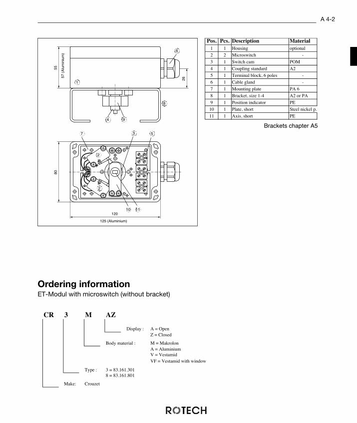
Pos. Pcs. Description Material1 1 Housing optional
2 2 Microswitch -
3 1 Switch cam POM
4 1 Coupling standard A2
5 1 Terminal block, 6 poles -
6 1 Cable gland -
7 1 Mounting plate PA 6
8 1 Bracket, size 1-4 A2 or PA
9 1 Position indicator PE
10 1 Plate, short Steel nickel p.
11 1 Axis, short PE
55
120
125 (Aluminium)
57 (
Alu
min
ium
)
26
80
CR 3 M AZ
Display : A = OpenZ = Closed
Body material : M = MakrolonA = AluminiumV = VestamidVF = Vestamid with window
Type : 3 = 83.161.3018 = 83.161.801
Make: Crouzet
Ordering informationET-Modul with microswitch (without bracket)
1
7
8
9
6
5
4
3
10 11
2
2
Brackets chapter A5
A 4-2

Contact Free Operated Signal Device ET-Housing
The ET-module with 3-wire proximity sensor convertsthe mechanical end or middle positions of the actuatorinto electrical signals.In many european countries the proximity signal deviceis used for NON-Ex applications.It is extra secure in its switching performance, becauseit possesses a negligible residual current at blockedstate, and a minimal potential drop at switched state.The coupling of the modul balances possible bumps ofthe bracket and guarantees a full transmission at thethe actuators shaft.
Manufacturer: Pepperl + FuchsType: NBN 4-12GM50-E2
induktiv, NO, DC PNPSwitch distance: 4 mmNom. voltage: 10 - 30 V DCContinous current: 200 mAOpen circuit current: ≤ 15 mAOutput: short circuit proof, reverse polarity prot.
undamped ≤ 0,3 V, damped ≥ Us - 3 V
Display: LED, yellowTemperature range: -25 ... +70 °CHousing: Makrolon, grey with clear cover
( Polycarbonat )Vestamid, black (shock-proof Polyamid 6.6)
alternative with window material PolycarbonatAluminium, industry grey ( GD AL SI 12 )
Sealing: Silicon (alternative Neoprene)Ingress protection: IP 67 for sensor, IP 65 for housing
acc. IEC 529 / DIN 40 050Switching precision
of unit: ≤ 0,5°Connection: M20 x 1,5
• easy and precise adjusting of theend positions
• secure control through a stain-less steel flag
• symetrical design, easy to mount
3-Wire-Contact Free Sensor
ADVANTAGES
WIRING DIAGRAM
A 4-3
BU
BK
BU
BN
open Auf
ouvert
1
2
3
4
5
6
closed Zu
fermé
BK
BN
TECHNICAL DATA

Pos. Pcs. Description Material1 1 Housing optional
2 2 Proximity sensor -
3 1 Mounting flag Alu
4 1 Switch flag A2
5 1 Axis NJ A2
6 1 Terminal block, 6 poles -
7 1 Cable gland -
8 1 Mounting plate PA 6
9 1 Bracket, size 1-4 A2 or PA
10 1 Position indicator PE
55
120
125 (Aluminium)
57 (
Alu
min
ium
)
26
80
A 4-4
Ordering informationET-Modul with proximity sensor (without bracket)
Basically it is possible to mount proxi-mity sensors form different manufactu-rers into the ET-box.The max. mounting size of the sensorfor the standard box is M18 x 50mm(without cable entry).Special sizes upon request.
PF N412E V AZ
Display : A = OpenZ = Closed
Body material M = MakrolonA = AluminiumV = VestamidVF = Vestamid with window
Type : NBN4-12GM50-E2
Make : Pepperl + Fuchs
1
7
8
9
6
5
4
3
10
2
2
Brackets chapter A5

TECHNICAL DATA
Contact Free Operated Signal Devices With Housing
The slotted sensor unit converts the end positions ormiddle positions of the actuator into electrical signals.The slotted sensor is commonly used in the chemical in-dustry and generally in applications requiring explosionprotection. But 2-wire technology is also increasinglyapplied in mechanical engineering.The slotted proximity sensor is intrinsically safe becauseof the low potential. There is no need for an additionalexplosion protection installation.The spring coupling compensates for any irregularities inthe mount bracket and guarantees a positive location inthe actuator shaft.An additional yellow arrow high visibility position indica-tor displays the position of the actuator. The fully adju-stable serrated cams are locked together to ensure thatthe adjusted setting is secured against any vibration.
ADVANATGES
Manufacturer: Pepperl + Fuchs Pepperl + FuchsType: SJ 3,5 N SJ 5 N
slotted sensor, NC, Namur (DIN 19 234)Nom. voltage: 8 V DC 8 V DCWorking voltage: 5 .. 25 V DC 5 .. 25 V DCOutput: short-circuit proof
undamped ≥ 3 mA, damped ≤ 1 mAHousing: Makrolon, light grey
( Polycarbonate with clear cover )Vestamid, black (shock proof polyamide 6.6)
optional with a window of polycarbonateAluminium, industrial grey ( GD AL SI 12 )
Sealing: Silicon (optional neoprene)Ingress protection: sensor: IP 67, housing: IP 65
acc. to IEC 529 / DIN 40 050Switching precision: ≤ 0.5°Cable gland: M20 x 1.5Temp. range: - 25 to + 70 °C
• The end position can be dam-ped or undamped
• high switching precision througha large disc diameter
• switching positions can be adju-sted independently.
A 4-5
WIRING DIAGRAM
41
42
51
52
BU
BNclosed
Zu fermé
BU
BN
open Auf
ouvert
+ -
+ -
GW 2
GW 1
EExi - Slotted Proximity

Pos. Pcs. Description Material1 1 Housing optional
2 2 Slotted sensor -
3 2 Plate SJ PA 6
4 2 Switch cam A2
5 1 Axis standard A2
6 2 Terminal block, 2 poles -
7 1 Cable gland -
8 1 Mounting plate PA 6
9 1 Bracket, size 1-4 A2 or PA
10 1 Position indicator PE
11 1 Plate Steel, nickel p.
12 1 Axis, long PE
55
GW1
GW2
120
125 (Aluminium)
57 (
Alu
min
ium
)
26
80
A 4-6
PF 3 N A AZ
Display : A = OpenZ = Closed
Body material : M = MakrolonA = AluminiumV = VestamidVF = Vestamid with window
Type : N = ... - NS = ... - SN
Slot size : 3 = 3,5mm5 = 5mm
Make : PF = Pepperl + FuchsTU = Turck
Ordering informationET-module with microswitch (without bracket)
1
7
8
9
6
5
43
10
11 12
2
2
Brackets chapter A5

Brackets For Signal DevicesROTECH ET-brackets provide alternative possibilities for mounting signal devices(e.g. switch boxes) to actuators and valves.The bracket program is especially designed to fit actuators with connections accordingto VDI/VDE 3845. It includes brackets to mount standard limit-switch boxes, bracketswith handlever lock-off facility and brackets to fix limit-switch units directly onto ma-nually operated valves.
A 5-1
AB
C
Actuator Shaft heightsize A B C
0 50 20/25 20
1 80 30 20
2 80 30 30
3 130 30 30
4 130 30 50
Dim. of drillsActuator sizesacc. VDI/VDE 3845

Pluggable Univer-salbracket
Polyamid
Stainless SteelBrackets
ADVANTAGES
beginning page A5-7
beginning page A5-3
• robust stainless steel construc-tion
• easy adaptation of the actuators shaft height with 4 sizes• slim design and easy mounting of the TCR- bracket
ADVANTAGES
• quickest mounting• fits sizes 2 and 3 by turning feet 180°• optimised design for TCR- and PB/ET- series
QUICK MOUNTING:
• Mount feet onto actuator with twoscrews
• Plug switchbox and brackets baseonto feet
A 5-2

A 5-3
Pluggable Universal Bracket - Polyamid for TCR- series
45
80 x 30
F05 DIN ISO 5211
Universal bracket UBT1
Universal bracket for actuators Size 1VDI/VDE 3845
QUICK MOUNTING
• Fix brackets feet with enclosedscrews onto the actuator
• Plug on switchbox with mountedbracket-plate

A 5-4
Universal Bracket for actuators size 4acc.
VDI/VDE 3845
Universalbracket UBT23
Universalbrackets for actuatorssizes 2 and 3 acc.VDI/VDE 3845
Sizes 2 or 3 depending on arrangementof feet
55
80 x 30
55
130 x 30
F05 DIN ISO 5211
F05 DIN ISO 5211
UB T 1
Size : dim. of drills Pinion height
1 = Size 1: 80 x 30 20mm
23 = Size 2+3: 80/130 x 30 30mm
4 = Size 4: 130 x 30 50mm
T = for TCR-series
UB = Universalbracket
75130 x 30
F05 DIN ISO 5211
Ordering informationUniversalbracket TCR-Design
2x screws M5x8 DIN 912 einclosed
A 5-5
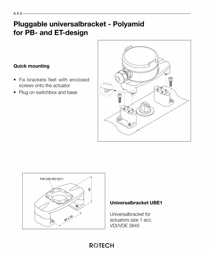
Pluggable universalbracket - Polyamidfor PB- and ET-design
45
80 x 30
F05 DIN ISO 5211
Universalbracket UBE1
Universalbracket foractuators size 1 acc.VDI/VDE 3845
Quick mounting
• Fix brackets feet with enclosedscrews onto the actuator
• Plug on switchbox and base
A 5-6
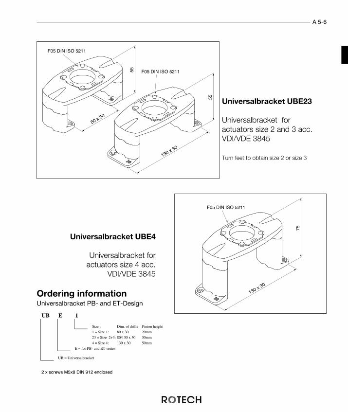
Universalbracket UBE4
Universalbracket for actuators size 4 acc.
VDI/VDE 3845
Universalbracket UBE23
Universalbracket foractuators size 2 and 3 acc.VDI/VDE 3845
Turn feet to obtain size 2 or size 3
55
80 x 30
55
130 x 30
F05 DIN ISO 5211
F05 DIN ISO 5211
UB E 1
Size : Dim. of drills Pinion height
1 = Size 1: 80 x 30 20mm
23 = Size 2+3: 80/130 x 30 30mm
4 = Size 4: 130 x 30 50mm
E = for PB- and ET-series
UB = Universalbracket
75130 x 30
F05 DIN ISO 5211
2 x screws M5x8 DIN 912 enclosed
Ordering informationUniversalbracket PB- and ET-Design
A 5-7
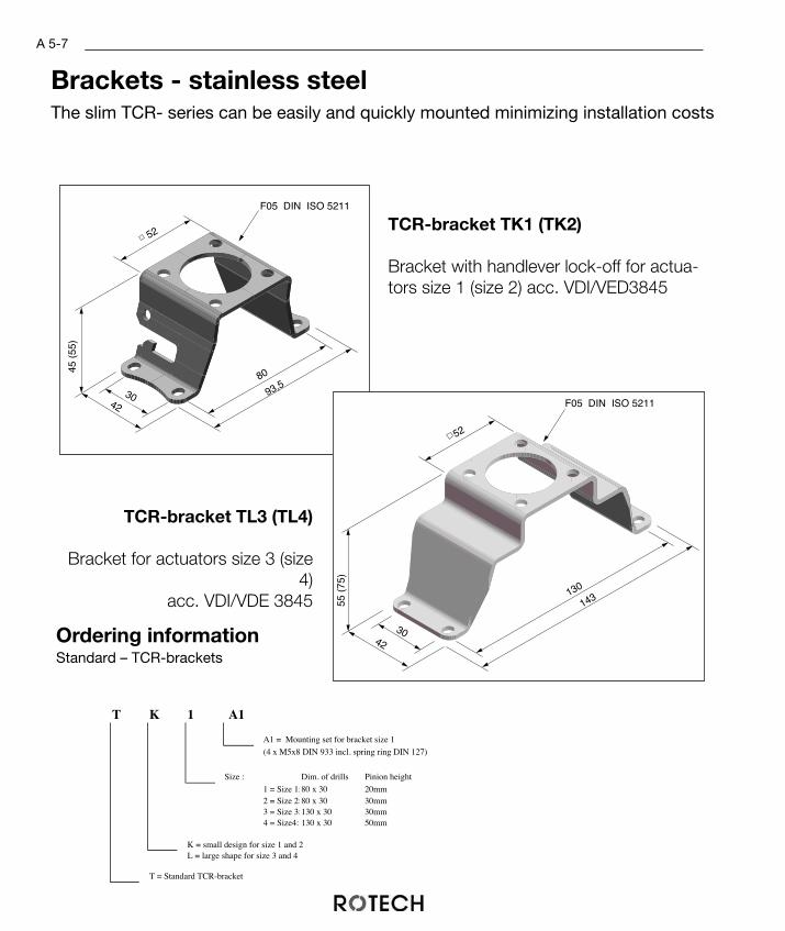
Brackets - stainless steelThe slim TCR- series can be easily and quickly mounted minimizing installation costs
TCR-bracket TL3 (TL4)
Bracket for actuators size 3 (size4)
acc. VDI/VDE 3845
93,580
30
45 (
55)
52
F05 DIN ISO 5211
42
TCR-bracket TK1 (TK2)
Bracket with handlever lock-off for actua-tors size 1 (size 2) acc. VDI/VED3845
T K 1 A1
A1 = Mounting set for bracket size 1
(4 x M5x8 DIN 933 incl. spring ring DIN 127)
Size : Dim. of drills Pinion height
1 = Size 1:80 x 30 20mm2 = Size 2:80 x 30 30mm3 = Size 3:130 x 30 30mm4 = Size4: 130 x 30 50mm
K = small design for size 1 and 2L = large shape for size 3 and 4
T = Standard TCR-bracket
55 (
75)
52
F05 DIN ISO 5211
130
143
42
30Ordering informationStandard – TCR-brackets
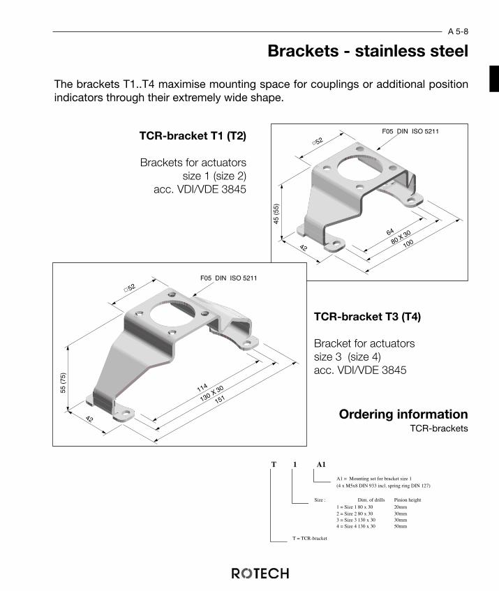
T 1 A1
A1 = Mounting set for bracket size 1
(4 x M5x8 DIN 933 incl. spring ring DIN 127)
Size : Dim. of drills Pinion height
1 = Size 1 80 x 30 20mm2 = Size 2 80 x 30 30mm3 = Size 3 130 x 30 30mm4 = Size 4 130 x 30 50mm
T = TCR-bracket
A 5-8
TCR-bracket T1 (T2)
Brackets for actuators size 1 (size 2)
acc. VDI/VDE 3845
TCR-bracket T3 (T4)
Bracket for actuators size 3 (size 4)acc. VDI/VDE 3845
Brackets - stainless steel
The brackets T1..T4 maximise mounting space for couplings or additional positionindicators through their extremely wide shape.
64
45 (
55)
52F05 DIN ISO 5211
42 10080 X 30
Ordering informationTCR-brackets
114
55 (
75)
52F05 DIN ISO 5211
151
42
130 X 30

A 5-9
TCR-bracket T0
Brackets for actuators si-ze 0
34
30
52
F05 DIN ISO 5211
70
45
42 50 x 20
50 X 25
Brackets - stainless steel
Very compact bracket, especially for small actuators.
T 0 A1
A1 = Mounting set for bracket size 1
(4 x M5x8 DIN 933 incl. spring ring DIN 127)
Dim. of drills Pinion height
Size : 0 = Size 0:50 x 25/30 20mm
T = TCR-bracket
Ordering informationTCR-bracket size 0

A 5-10
ET-bracketsize 3 (size 4)
Bracket for mounting limit-switchunits on actuators size 3 (size 4)
acc. VDI/VDE 3845
ET-bracketsize 1 (size 2)
Bracket for mounting limit-switch units onactuators of size 1 (size2)acc. VDI/VDE 3845
Ordering information
50
45 (
55)
72
80 x 30
120
F05 DIN ISO 5211
ET 1 A1
A1 = Mounting set for bracket size 1
(4 x M5x8 DIN 933 incl. spring ring DIN 127)
Size : Dim. of drills Pinion height
1 = Size 1 80 x 30 20mm2 = Size 2 80 x 30 30mm3 = Size 3 130 x 30 30mm4 = Size 4 130 x 30 50mm
ET = Standard ET-bracket
ET-Bracket - stainless steel
The standard ET-bracket available in four sizes allows an easy adjustment tothe actuator axis.
F05 DIN ISO 5211
50
55 (
75)
120
122
130 x 30
170
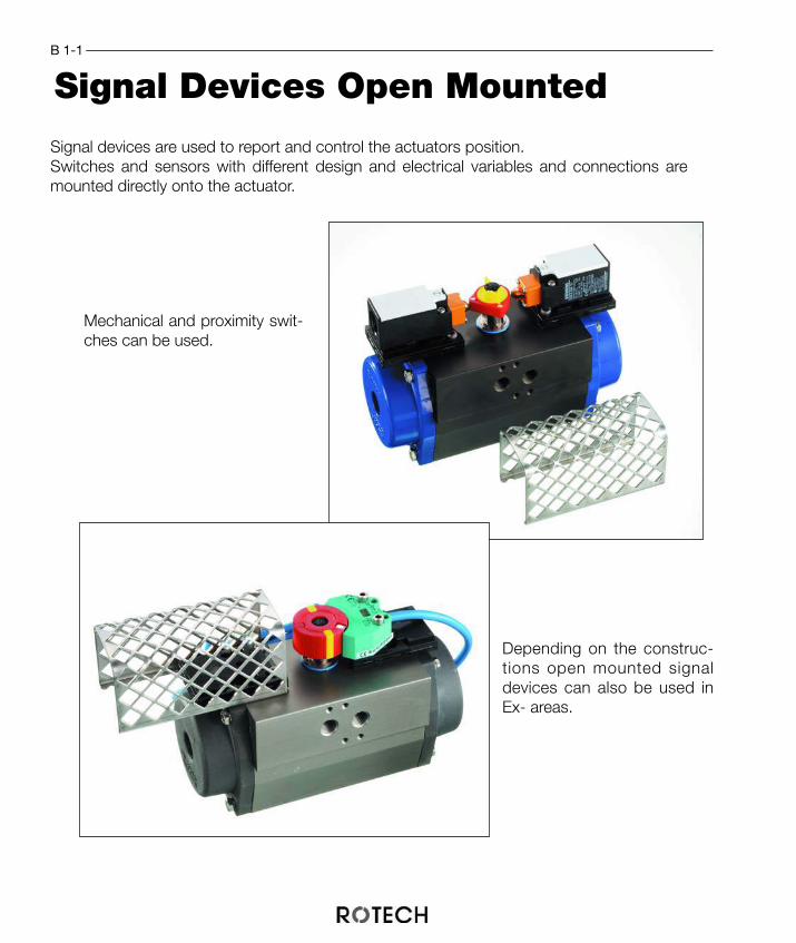
Signal Devices Open MountedB 1-1
Signal devices are used to report and control the actuators position.Switches and sensors with different design and electrical variables and connections aremounted directly onto the actuator.
Mechanical and proximity swit-ches can be used.
Depending on the construc-tions open mounted signaldevices can also be used inEx- areas.

Universal Plate For Direct Mounting
ADVANTAGES
• universal mounting on all actuators acc. VDI/VDE 3845• Adaptation in height by easily stacking the plates• Dimension of drills acc. DIN/EN 50 047
The universal plate with its unique construction-kit-system easily solves your monito-ring problems. The mounting of a complete switch unit is really easy, and can individu-ally be assembled for all monitoring applications and requirements.The universal plate is used as a carrier for switches, sensors, terminal blocks and pro-tection cages when you are directly mounting onto an actuator according toVDI/VDE3845 and DIN/EN50 047.
B 2-1
1013
3048
66
UNIPL KPL
with screw socket
Universalplate
Ordering informationUniversal plate

B 3-1
The different types of switching cams are made of an abrasion-free, fibreglass reinfor-ced material. They can be used with mechanical position switches or proximity swit-ches.
• reliable operation of the switches by direct fixingto the shaft (according to VDI/VDE 3845)
• free stacking and adjustable to 3°• metal inserts allow the use of inductive proximity
sensors• cams are adjustable to any height of the switches
by serrated distance sleeves
ADVANTAGES
Switching Cam System

Standard switchingcams
with 1 or 2 cams
B 3-2
The standard switching cams allow the use ofmechanical and inductive limit switches. Theycan be combined in any configuration and beused with right or left turning valves.
The 5 mm - switching cam for smal-lest dimensions is designed only formechanical operation.
Standard Switching Cams
SNO 10 1 L
L = anticlockwiseR = clockwise
Quantitiy cams: 1 = one cam2 = two cams
Size: 5 = 5 mm10 = 10 mm
SNO = Switching cam
Ordering informationSwitching Cams
SNO102L
SNO102R
SNO101R
SNO101L
SNO5
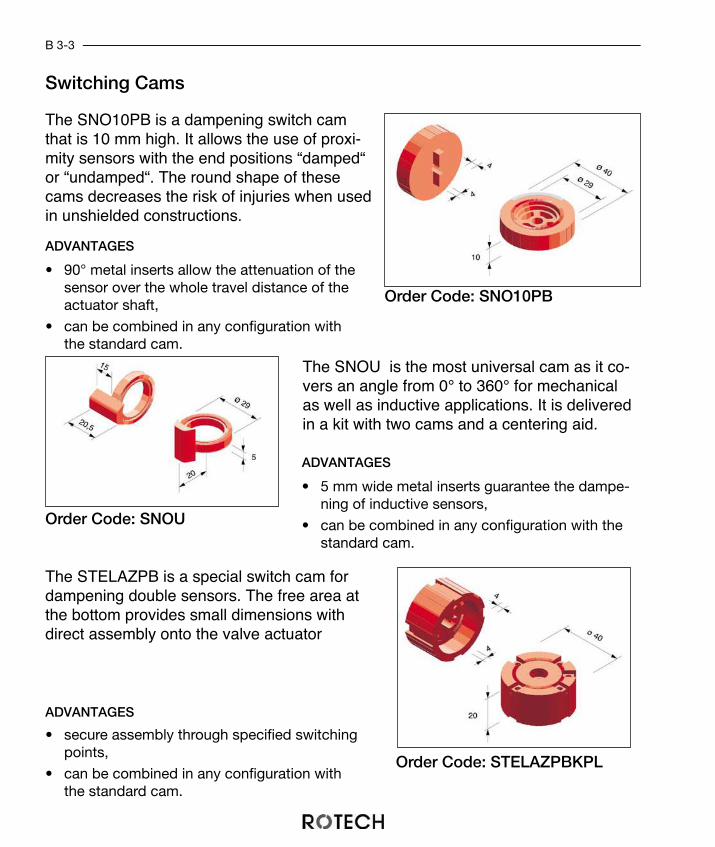
The SNO10PB is a dampening switch camthat is 10 mm high. It allows the use of proxi-mity sensors with the end positions “damped“or “undamped“. The round shape of thesecams decreases the risk of injuries when usedin unshielded constructions.
The SNOU is the most universal cam as it co-vers an angle from 0° to 360° for mechanicalas well as inductive applications. It is deliveredin a kit with two cams and a centering aid.
The STELAZPB is a special switch cam fordampening double sensors. The free area atthe bottom provides small dimensions withdirect assembly onto the valve actuator
• 90° metal inserts allow the attenuation of thesensor over the whole travel distance of theactuator shaft,
• can be combined in any configuration withthe standard cam.
ADVANTAGES
• secure assembly through specified switchingpoints,
• can be combined in any configuration withthe standard cam.
ADVANTAGES
• 5 mm wide metal inserts guarantee the dampe-ning of inductive sensors,
• can be combined in any configuration with thestandard cam.
ADVANTAGES
Switching Cams
Order Code: SNO10PB
Order Code: SNOU
Order Code: STELAZPBKPL
B 3-3
B 3-4
Ordering informationPosition indicators
Or-dering informationSpacer rings
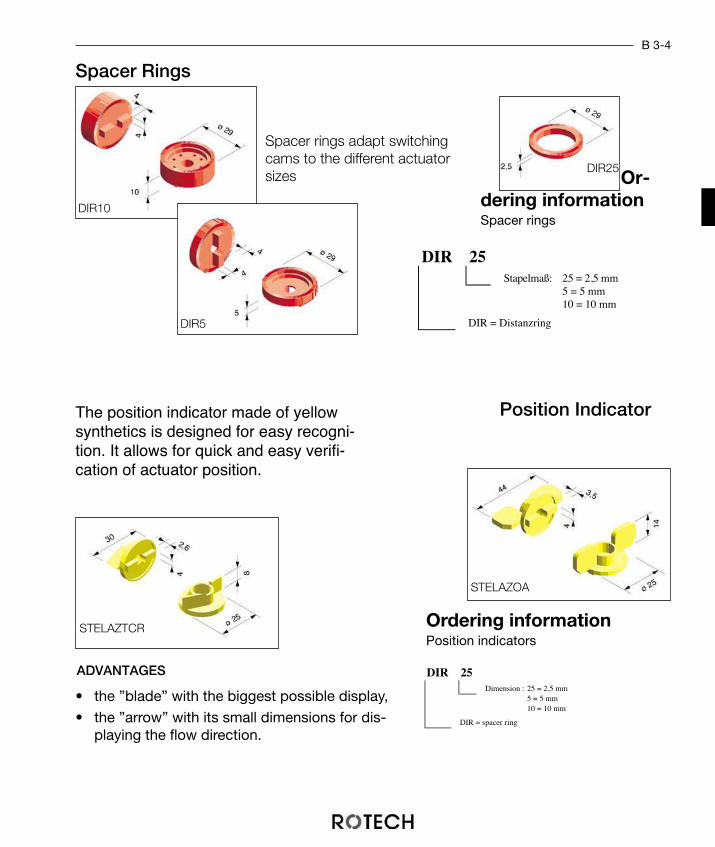
The position indicator made of yellowsynthetics is designed for easy recogni-tion. It allows for quick and easy verifi-cation of actuator position.
• the ”blade” with the biggest possible display,
• the ”arrow” with its small dimensions for dis-playing the flow direction.
ADVANTAGES
Position Indicator
Spacer Rings
Spacer rings adapt switchingcams to the different actuatorsizes
DIR 25Stapelmaß: 25 = 2,5 mm
5 = 5 mm10 = 10 mm
DIR = Distanzring
DIR 25Dimension : 25 = 2,5 mm
5 = 5 mm10 = 10 mm
DIR = spacer ring
DIR10
DIR5
STELAZTCR
STELAZOA
DIR25

B 4-1
Mechanically operated signal devicesopen design
ADVANTAGES• economies of scale achieved through standardised dimensions and
large production runs,• universal use through the UNI-sandwich-mounting-system,• the stainless steel cover provides the necessary protection against
touching.
ET-KIT
The ET-Kit with position switches convertsthe mechanical end positions of pneumaticactuators into electrical signals.The most common use of the mechanicalposition switch is in mechanical engineeringand in general industry. The ET-Kit with its protective cover conformsto the applicable protection regulations ofthe EC.
By choosing between different cams itis possible to change switching pointsfrom „fix“ to „variable“
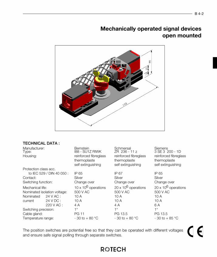
Mechanically operated signal devicesopen mounted
TECHNICAL DATA :Manufacturer: Bernstein Schmersal SiemensType: I88 - SU1Z RIWK ZR 236 - 11 z 3 SE 3 200 - 1DHousing: reinforced fibreglass reinforced fibreglass reinforced fibreglass
thermoplaste thermoplaste thermoplasteself extinguishing self extinguishing self extinguishing
Protection class acc.to IEC 529 / DIN 40 050 : IP 65 IP 67 IP 65
Contact: Silver Silver SilverSwitching function: Change over Change over Change over
Mechanical life: 10 x 106 operations 20 x 106 operations 20 x 106 operationsNominated isolation voltage: 500 V AC 500 V AC 500 V ACNominated 24 V AC : 10 A 10 A 10 Acurrent 24 V DC : 10 A 10 A 10 A
220 V AC : 4 A 4 A 6 ASwitching precision: 1° 1° 1°Cable gland: PG 11 PG 13.5 PG 13.5Temperature range: - 30 to + 80 °C - 30 to + 80 °C - 30 to + 85 °C
The position switches are potential free so that they can be operated with different voltagesand ensure safe signal polling through separate switches.
B 4-2

Pos. Pcs. Description Material1 2 UNI-sandwichplate com. PPO
2 4 M5 x 12 - DIN 912 A23 1 Switch cam SNO102R POM, A2
4 1 Position indicator PE
5 1 M6 x 20 - DIN 912 A2
6 1 Cover cap M6 PA
7 2 Switch -8 4 M4 x 24 - DIN 84 A2
9 1 Protection cage A2
Display ”CLOSED” - fixedDisplay ”OPEN” - fixed
B 4-3
The ET-Kit, assembled with the switchcam SNO102, displays fixed end positi-ons 0° and 90°.
It combines easy assembly with minimalcomponents and is provided for left aswell as right turning actuators. The fle-xible set system allows an adaption toall sizes of actuators according toVDE/VDI 3845.
Pos. Pcs. Description Material1 3 UNI-sandwichplate compl. PPO
2 2 M5 x 12 - DIN 912 A2
3 2 M5 x 22 - DIN 913 A24 2 Switch cam SNO101R POM, A2
5 1 Position indicator PE
6 1 M6 x 30 - DIN 912 A2
7 1 Abdeckkappe M6 PA
8 2 Cover cap M6 -9 4 M4 x 24 - DIN 84 A2
10 1 Protection cage A2
Display „CLOSED” – fixedDisplay „OPEN” – variabelThe ET-Kit, assembled with the switch
cam SNO101, is fixed for the end posi-tions “CLOSED“. The position “OPEN“can be adjusted to the requirements ofthe application.This unit provides easy assembly withhigh flexibility. It is provided for left aswell as right turning actuators accor-ding to VDE/VDI 3845.
1
89
4
1
7
8
9
6
5
4
310
2
1
7
8
9
6
5
4
3
2
1
7
8
2

B 4-4
Pos. Pcs. Description Material1 2 UNI-sandwichplate comp. PPO
2 4 M5 x 12 - DIN 912 A2
3 1 Distance ring DIR25 POM4 1 Switch can kit SNOU POM, A2
5 1 Position indicator PE
6 1 M6 x 30 - DIN 912 A2
7 1 Cover cap M6 PA
8 2 Switch -9 4 M4 x 24 - DIN 84 A2
10 1 Protection cage A2
Display ”CLOSED” - variable
Display ”OPEN” - variable
The ET-Kit, assembled with the switch camSNOU, converts the variable end positionsof the actuator into electrical signals.The unit provides easy assembly with highflexibility in the choice of the switchingpoints. It is provided for left as well as rightturning actuators according to VDE/VDI3845.
Ordering informationET-Kit mechanical
BE 88SU O AZ 1 DR
DR = SNO102R (1x) "Closed" fix, "Open" fixER = SNO101R (2x) "Closed" fix, "Open" variableUK = SNOUKIT (1x) "Closed" variable, "Open" variable
Size : 1 = Size 12 = Size 23 = Size 34 = Size 4
Display : A = OpenZ = Closed
O = open mounted
Type : 88SU = I88-SU 1Z RIWK236 = ZR 236-11 z200 = 3 SE 3 200-1D
Make : BE = BernsteinSC = SchmersalSI = Siemens
1
7
8
9
6
5
4
3
10
2
1
8
9 2
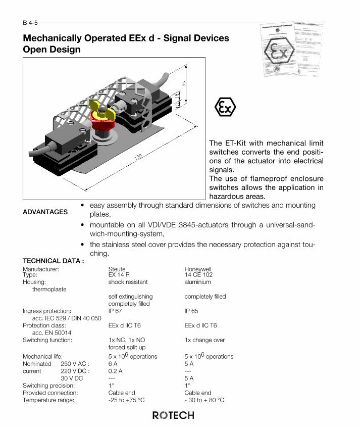
• easy assembly through standard dimensions of switches and mountingplates,
• mountable on all VDI/VDE 3845-actuators through a universal-sand-wich-mounting-system,
• the stainless steel cover provides the necessary protection against tou-ching.
B 4-5
The ET-Kit with mechanical limitswitches converts the end positi-ons of the actuator into electricalsignals.The use of flameproof enclosureswitches allows the application inhazardous areas.
Mechanically Operated EEx d - Signal DevicesOpen Design
TECHNICAL DATA :Manufacturer: Steute HoneywellType: EX 14 R 14 CE 102Housing: shock resistant aluminium
thermoplasteself extinguishing completely filledcompletely filled
Ingress protection: IP 67 IP 65acc. IEC 529 / DIN 40 050
Protection class: EEx d IIC T6 EEx d IIC T6acc. EN 50014
Switching function: 1x NC, 1x NO 1x change overforced split up
Mechanical life: 5 x 10⁶ operations 5 x 10⁶ operationsNominated 250 V AC : 6 A 5 Acurrent 220 V DC : 0.2 A ---
30 V DC --- 5 ASwitching precision: 1° 1°Provided connection: Cable end Cable endTemperature range: -25 to +75 °C - 30 to + 80 °C
ADVANTAGES

Ordering informationET-Kit Honeywell, Ex-areas
ST E14R O AZ 1
Size : 1 = Size 12 = Size 23 = Size 34 = Size 4
Display : A = OpenZ = Closed
O = open mounted
Type E14R = Ex 14 R
Make : ST = Steute
HO 14CE O AZ 1
Size : 1 = Size 12 = Size 23 = Size 34 = Size 4
Display : A = OpenZ = Closed
O = open mounted
Type 14CE = 14 CE 102
Make : HO = Honeywell
B 4-6
Pos. Pcs. Description Material1 2 UNI-sandwichplate com. PPO
2 2 Adapterplate Al
3 4 M5 x 22 - DIN 963 A24 1 Switch cam SNO102R POM, A2
5 1 Position indicator PE
6 1 M6 x 20 - DIN 912 A2
7 1 Cover cap M6 PA
8 2 Honeywell 14 CE 102 -9 4 M5 x 12 - DIN 912 A2
10 1 Protection cage A2
Pos. Pcs. Description Material1 4 UNI-sandwichplate compl. PPO
2 4 M5 x 22 - DIN 912 A23 1 Switch cam SNO102R POM, A2
4 1 Position indicator PE
5 1 M6 x 20 - DIN 912 A2
6 1 Cover cap M6 PA
7 2 Steute Ex 14 R -8 4 M4 x 16 - DIN 84 A2
9 1 Protection cage A2
1
7
8
6
5
4
3
2
1
7
8
9 2
1
7
8
9
6
5
43
2
1
89
310
2
Ordering informationET-Kit Steute, Ex-areas

ADVANTAGES
The ET-Kit with proximity switches con-verts the end or middle positions of pneu-matic actuators into electrical signals. Be-cause of their compact design doubleinductive proximity switches of differentmanufacturers are best used in this kit.
• independent adjustment of each switching pointin the range from 0° to 360°,
• the UNI-sandwich-system provides an adaptionof the switches to all standard shaft heights,
• can be mounted universally on all actuators ac-cording to VDI/VDE 3845.
Contact Free Operated Signal DevicesOpen Design
B 4-7
Depending on the type of switch, the sig-nal device is provided with a cable end, aM12-plug connection or an integrated ter-minal box.
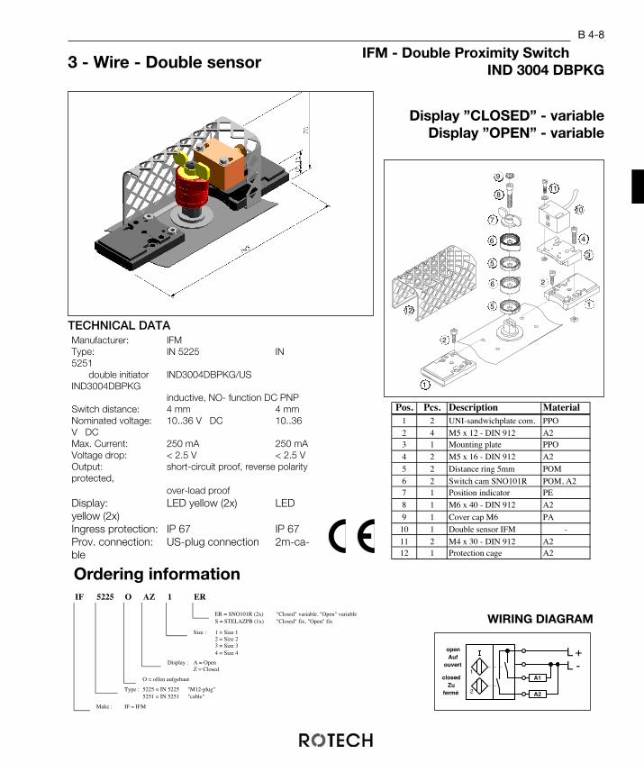
TECHNICAL DATAManufacturer: IFMType: IN 5225 IN5251
double initiator IND3004DBPKG/USIND3004DBPKG
inductive, NO- function DC PNPSwitch distance: 4 mm 4 mmNominated voltage: 10..36 V DC 10..36V DCMax. Current: 250 mA 250 mAVoltage drop: < 2.5 V < 2.5 VOutput: short-circuit proof, reverse polarityprotected,
over-load proofDisplay: LED yellow (2x) LEDyellow (2x)Ingress protection: IP 67 IP 67Prov. connection: US-plug connection 2m-ca-ble
IFM - Double Proximity SwitchIND 3004 DBPKG3 - Wire - Double sensor
B 4-8
Display ”CLOSED” - variableDisplay ”OPEN” - variable
1
7
8
9
6
5
4
3
10
11
12
2
1
6
5
2
IF 5225 O AZ 1 ER
ER = SNO101R (2x) "Closed" variable, "Open" variableS = STELAZPB (1x) "Closed" fix, "Open" fix
Size : 1 = Size 12 = Size 23 = Size 34 = Size 4
Display : A = OpenZ = Closed
O = offen aufgebaut
Type : 5225 = IN 5225 "M12-plug"5251 = IN 5251 "cable"
Make : IF = IFM
Pos. Pcs. Description Material1 2 UNI-sandwichplate com. PPO
2 4 M5 x 12 - DIN 912 A23 1 Mounting plate PPO
4 2 M5 x 16 - DIN 912 A2
5 2 Distance ring 5mm POM
6 2 Switch cam SNO101R POM, A27 1 Position indicator PE
8 1 M6 x 40 - DIN 912 A2
9 1 Cover cap M6 PA
10 1 Double sensor IFM -
11 2 M4 x 30 - DIN 912 A212 1 Protection cage A2
WIRING DIAGRAM
open Auf
ouvert
closed Zu
fermé
1
2
A1
A2
L -L +
Ordering information

PF F25N O AZ 1 P
P = SNO10PB (2x) "Closed" variable, "Open" variable
Size : 1 = Size 12 = Size 23 = Size 34 = Size 4
Display : A = OpenZ = Closed
O = offen aufgebaut
Type : F25N = NCN3-F25F-N4 "cable"F25NV = NCN3-F25F-N4-V1 "M12-plug"
Make : PF = Pepperl + Fuchs
TECHNICAL DATAManufacturer: Pepperl + FuchsType: NCN3 - F25F - N4 (-V1)
Doublesensor induktive, 2-wireNCNAMUR (DIN 19 234)
Switch distance: 3 mmNom. voltage: 8 V DCCur. cunsumption: damped ≤ 1 mA
undampedt ≥ 3 mAOutput: reverse polarity protected, short-cir-cuit proofDisplay LED yellow (2x)Ingress protection: IP 67Prov. connection: 5 m cable end or
M12-plug connectionTemp. range: -25 ... +100 °C
Pepperl + Fuchs - Double Sensor EEx i - Double SensorNCN3 - F25F - N4
Display „CLOSED” – varia-bel
Display „OPEN” – variabel
WIRING DIGRAM2-wire, NAMUR
2
1
+-+
-closed
Zu fermé
open Auf
ouvert
BN
WH
BU
BK
Pos. Pcs. Description Material1 3 UNI-sandwichplate compl. PPO
2 2 M5 x 12 - DIN 912 A2
3 1 Distance ring 5mm POM
4 2 Switch cam SNO10PB POM, A2
5 1 Position indicator PE
6 1 M6 x 35 - DIN 912 A2
7 1 Cover cap M6 PA
8 1 P + F, NCN3 - F25 - N4 -
9 2 M5 x 50 - DIN 912 A2
10 1 Protection cage A2
7
8
10
96
5
4
4
3
2
1
1
Ordering information

B 4-10
WIRING DIAGRAM3-wire, PNP
open Auf
ouvert
closed Zu
fermé
1
2
A1
A2
L -L +
TECHNCAL DATAManufacturer: Pepperl + FuchsType: NBN3 - F25F - E8 (-V1)
Double sensor induktive, 3-wireNODC PNP
Switch distance:3 mmNom. voltage: 10..30 V DCCur. consumtion: I0 ≤ 20 mAOutput:reverse polarity protected, short-circuit proofDisplay: LED yellow (2x)Ingress protection: IP 67Prov. connection: 5 m-cable end or
M12-plug connectionTemp. range: -25 ... +70 °C
3 - Wire - Doublesensor Pepperl + Fuchs – DoublesensorNBN3 – F25F – E8
Display „CLOSED – fixedDisplay „OPEN” – fixed
Pos. Pcs. Description Material1 2 UNI-sandwichplate compl. PPO
2 2 M5 x 12 - DIN 912 A2
3 1 Distance ring 5mm POM
4 1 Switch cam STELAZPB POM, A2
5 1 M6 x 25 - DIN 912 A2
6 1 Cover cap M6 PA
7 1 P + F, NBN3 - F25 - E8 -
8 2 M5 x 40 - DIN 912 A2
9 1 Protection cage A2
7
8
9
6
5
4
3
2
1
1
PF F25E O AZ 1 ER
ER = SNO101R (2x) "Closed" variable, "Open" variableS = STELAZPB (1x) "Closed" fix, "Open" fix
Size : 1 = Size 12 = Size 23 = Size 34 = Size 4
Display : A = OpenZ = Closed
O = offen aufgebaut
Type : F25E = NBN3-F25F-E8 "cable"F25EV = NBN3-F25F-E8-V1 "M12-plug"
Make : PF = Pepperl + Fuchs
Ordering Information

B 4-11
Pos. Pcs. Description Material1 2 UNI-sandwichplate compl. PPO
2 4 M5 x 12 - DIN 912 A2
3 1 Mounting plate PPO
4 1 Distance ring 5mm POM
5 2 Switch cam SNO101R POM, A2
6 1 Position indicator PE
7 1 M6 x 35 - DIN 912 A2
8 1 Cover cap M6 PA
9 1 Double sensor TURCK -
10 2 M4 x 40 - DIN 912 A2
11 1 Protection cage A2
TECHNICAL DATAManufacturer: Turck TurckType: Ni4-DS20-2AP6X2 Ni4-DS20-2Y0X2
double initiator inductive, 3-wire inductive, 2-wireNO, DC PNP NC, Namur
Switch distance: 4 mm 4 mmNom. voltage: 10..30 V DC 8.2 V DCCur. consumption: ID ≤ 200 mA damped ≤ 1 mA
undamped ≥ 2.2mAOutput: reverse polarity protected, short-circuit proof
Display: LED, yellow ( 2x ) LED, red ( 2x )Ingress protection: IP 67 IP 67Prov. connection: 2m - cable end 2m - cable endTemp. range: - 25 to + 70 °C - 25 to + 70 °C
WIRING DIAGRAM3-wire, PNP 2-wire, NAMUR
open Auf
ouvert
closed Zu
fermé
1
2
A1
A2
L -L + open
Auf ouvert
closed Zu
fermé 2
- +
1
- +
Turck – Doublesensor 3-wire-DoublesensorNi4-DS20-2AP6X2, Ni4-DS20-2Y0X2 EEx i - Doublesensor
Display „CLOSED” – varia-bel
Display „OPEN” – variabel
7
8
9
6
5
4
10
11
2
1
5

TU 4DA O AZ 1 ER
ER = SNO101R (2x) "Closed" variable, "Open" variableP = SNO10PB (2x) "Closed" variable, "Open" variableS = STELAZPB (1x) "Closed" fix, "Open" fix
Size : 1 = Size 12 = Size 23 = Size 34 = Size 4
Display : A = OpenZ = Closed
O = open mounted
Typ : 4DA = Ni4-DS20-4AP6X2 "3-wire, cable"4DAH =Ni4-DS20-4AP6X2-H1141 "3-wire, M12-plug"4DY = Ni4-DS20-2Y0X2 "NAMUR, cable"4DYH = Ni4-DS20-2Y0X2-H1141 "NAMUR, M12-plug"
Make : TU = Turck
B 4-12
Ordering informationET-Kit induktive
M12-plug connector
For special purposes it may be neces-sary to have the wiring of the sensorsusing plug and socket connections. Forthis reason different sensors are provi-ded with a M12-plug connection. Asplugs are accessories they can be con-figured freely and so be adapted to alldifferent requirements. Ordering information
M12-plug connector
KD M12 G 4 PG9
PG9 - cable conduit
4 = no of poles
G = straightW = knee-version
M12 = M12-plug connection
KD = Plug connector
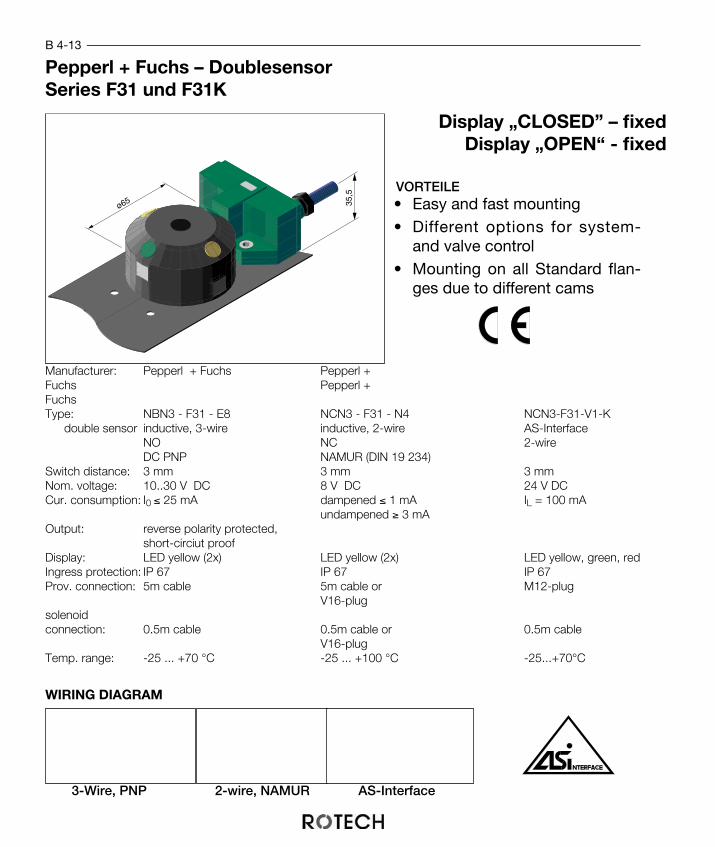
B 4-13
WIRING DIAGRAM
3-Wire, PNP 2-wire, NAMUR AS-Interface
35,5
ø65
Pepperl + Fuchs – DoublesensorSeries F31 und F31K
Display „CLOSED” – fixedDisplay „OPEN“ - fixed
Manufacturer: Pepperl + Fuchs Pepperl +Fuchs Pepperl +FuchsType: NBN3 - F31 - E8 NCN3 - F31 - N4 NCN3-F31-V1-K
double sensor inductive, 3-wire inductive, 2-wire AS-InterfaceNO NC 2-wireDC PNP NAMUR (DIN 19 234)
Switch distance: 3 mm 3 mm 3 mmNom. voltage: 10..30 V DC 8 V DC 24 V DCCur. consumption: I0 ≤ 25 mA dampened ≤ 1 mA IL = 100 mA
undampened ≥ 3 mAOutput: reverse polarity protected,
short-circiut proofDisplay: LED yellow (2x) LED yellow (2x) LED yellow, green, redIngress protection: IP 67 IP 67 IP 67Prov. connection: 5m cable 5m cable or M12-plug
V16-plugsolenoid connection: 0.5m cable 0.5m cable or 0.5m cable
V16-plugTemp. range: -25 ... +70 °C -25 ... +100 °C -25...+70°C
VORTEILE• Easy and fast mounting• Different options for system-
and valve control• Mounting on all Standard flan-
ges due to different cams

Pos. Pcs. Description Material1 1 P+F, NCN3-F31-... -
2 1 Cam -
3 2 M5 x 10 - DIN 912 A2
PF E O AZ 1
Display :
O = open mounted
System/solenoid : K = cable/without
el. construction : E = 3-wireN = 2 wire NAMURB = AS-Interface
F31 KK
Size : 1 = Size 12 = Size 23 = Size 34 = Size 4
A = Open
Make : Pepperl + Fuchs
Z = Closed
KK = cable/cableVV = plug V16/plug V16
Type : F31
PF F31K E KK O AZ 1
Size : 1 = Size 12 = Size 23 = Size 34 = Size 4
Display: A = "Open"Z = "Closed"
O = open mounted
Solenoid : _ = withoutK = 1x M12 x 1,5KK = 2 x M12 x 1,5
el. construction: E = 3-wireN = 2-wire NAMUR
Type : F31K
Make : Pepperl + Fuchs
Ordering informationET-Kit series F31
Ordering informationET-Kit Series F31K
B 4-14
3
2
1
Series F31Kterminal block
Series F31

C 1-1

Brackets
• The corresponding position of the axis of both flanges ensuresan in-line power transmission
• the use of high quality materials ensures consistent plane surfaces. Additional me-chanical finishes are available for special applications
• economic manufacturing through production in large batches.
The bracket or support is used to connect the actuator to the valve. The bracket to-gether with the coupling ensures an in-line and loss-free power transmission.ROTECH brackets have a standard flange according to DIN ISO 5211 for easy andquick connection of units from different manufacturers.
ADVANTAGES
C 1-2

Material :Steel, zinc-plated
Brackets with Double-sided Equal Flanges
C 1-3
Fl.1 Fl.2 l b* Dim. a x b* x s FacesF 03 F 03 35 40 80 x 40 x 4 parallel
F 03 F 03 35 50 80 x 50 x 4 parallelF 04 F 04 50 50 90 x 50 x 4 parallelF 05 F 05 55 60 100 x 60 x 5 parallelF 07 F 07 75 60 100 x 60 x 5 parallelF 10 F 10 95 80 140 x 80 x 6 parallelF 12 F 12 120 80 140 x 80 x 6 parallelF 14 F 14 135 90 160 x 90 x 6 parallelF 16 F 16 160 120 220 x 120 x 8 parallel
F 25 F 25 300 180 320 x 180 x 10 parallelF 30 F 30 320 200 400 x 200 x 12 parallel
* With milled surface : - 0,5 mm
a
b
l
Fl. 2
Fl. 1

Brackets With Doouble-sided Equal Flanges
Material :High grade steel
Material number:1.4301
C 1-4
Fl.1 Fl.2 l b* Dim. a x b* x s FacesF 03 F 03 35 40 80 x 40 x 4 parallel
F 03 F 03 35 50 80 x 50 x 4 parallelF 04 F 04 50 50 80 x 50 x 4 parallelF 05 F 05 55 60 100 x 60 x 4 parallelF 07 F 07 75 60 100 x 60 x 4 parallelF 10 F 10 95 80 140 x 80 x 5 parallelF 12 F 12 120 80 140 x 80 x 5 parallel
F 14 F 14 135 80 160 x 80 x 5 parallelF 16 F 16 160 100 200 x 100 x 6 parallel
* With milled surface : - 0,5 mm
a
b
l
Fl. 2
Fl. 1
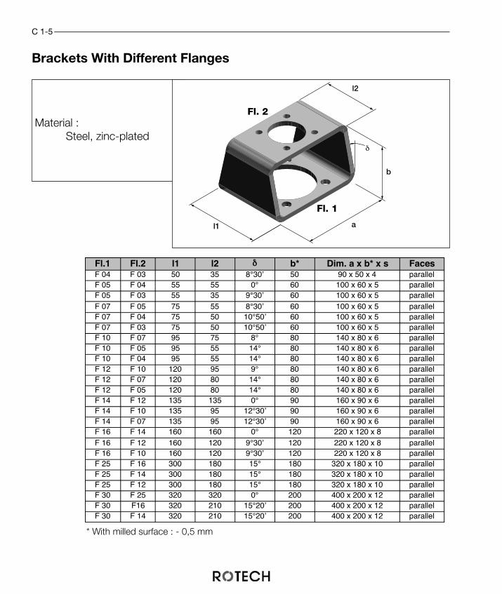
Brackets With Different Flanges
Material :Steel, zinc-plated
C 1-5
Fl.1 Fl.2 l1 l2 δ b* Dim. a x b* x s FacesF 04 F 03 50 35 8°30’ 50 90 x 50 x 4 parallelF 05 F 04 55 55 0° 60 100 x 60 x 5 parallelF 05 F 03 55 35 9°30’ 60 100 x 60 x 5 parallelF 07 F 05 75 55 8°30’ 60 100 x 60 x 5 parallelF 07 F 04 75 50 10°50’ 60 100 x 60 x 5 parallelF 07 F 03 75 50 10°50’ 60 100 x 60 x 5 parallelF 10 F 07 95 75 8° 80 140 x 80 x 6 parallelF 10 F 05 95 55 14° 80 140 x 80 x 6 parallelF 10 F 04 95 55 14° 80 140 x 80 x 6 parallelF 12 F 10 120 95 9° 80 140 x 80 x 6 parallelF 12 F 07 120 80 14° 80 140 x 80 x 6 parallelF 12 F 05 120 80 14° 80 140 x 80 x 6 parallelF 14 F 12 135 135 0° 90 160 x 90 x 6 parallelF 14 F 10 135 95 12°30’ 90 160 x 90 x 6 parallelF 14 F 07 135 95 12°30’ 90 160 x 90 x 6 parallelF 16 F 14 160 160 0° 120 220 x 120 x 8 parallelF 16 F 12 160 120 9°30’ 120 220 x 120 x 8 parallelF 16 F 10 160 120 9°30’ 120 220 x 120 x 8 parallelF 25 F 16 300 180 15° 180 320 x 180 x 10 parallelF 25 F 14 300 180 15° 180 320 x 180 x 10 parallelF 25 F 12 300 180 15° 180 320 x 180 x 10 parallelF 30 F 25 320 320 0° 200 400 x 200 x 12 parallelF 30 F16 320 210 15°20’ 200 400 x 200 x 12 parallelF 30 F 14 320 210 15°20’ 200 400 x 200 x 12 parallel
* With milled surface : - 0,5 mm
a
b
l2
Fl. 2
Fl. 1
l1
δ
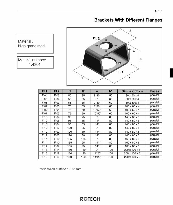
Brackets With Different Flanges
* with milled surface : - 0,5 mm
C 1-6
Fl.1 Fl.2 l1 l2 δ b* Dim. a x b* x s FacesF 04 F 03 50 35 8°30’ 50 80 x 50 x 4 parallel
F 05 F 04 55 55 0° 60 80 x 60 x 4 parallel
F 05 F 03 55 35 9°30’ 60 80 x 60 x 4 parallelF 07 F 05 75 55 8°30’ 60 100 x 60 x 4 parallelF 07 F 04 75 50 10°50’ 60 100 x 60 x 4 parallelF 07 F 03 75 50 10°50’ 60 100 x 60 x 4 parallelF 10 F 07 95 75 8° 80 140 x 80 x 5 parallelF 10 F 05 95 55 14° 80 140 x 80 x 5 parallelF 10 F 04 95 55 14° 80 140 x 80 x 5 parallelF 12 F 10 120 95 9° 80 140 x 80 x 5 parallel
F 12 F 07 120 80 14° 80 140 x 80 x 5 parallel
F 12 F 05 120 80 14° 80 140 x 80 x 5 parallel
F 14 F 12 135 135 0° 80 160 x 80 x 5 parallelF 14 F 10 135 95 14° 80 160 x 80 x 5 parallelF 14 F 07 135 95 14° 80 160 x 80 x 5 parallelF 16 F 14 160 160 0° 100 200 x 100 x 6 parallelF 16 F 12 160 120 11°20’ 100 200 x 100 x 6 parallelF 16 F 10 160 120 11°20’ 100 200 x 100 x 6 parallel
Material :High grade steel
Material number:1.4301
a
b
l2
Fl. 2
Fl. 1
l1
δ

Flange Data According To DIN ISO 5211 :
Ω/2
Ø d3
Ø d2
Ø d4
X
Ω/2
F03 F03 C 40 BFlange surfaces finished
Bracket height (if not standard)
Material: C = Steel, zinc-platedE = Stainless steel
Flange 2: F03...F30
Flange 1: F03...F30
Ordering informationBrackets
F03 - F30
Flange ø d2 H10 ø d3 x ø d4 Ω / 2F 03 25 36 25,5 5,5 45°F 04 30 42 29,7 5,5 45°F 05 35 50 35,4 6,5 45°F 07 55 70 49,5 9 45°F 10 70 102 72,1 11 45°F 12 85 125 88,4 13,5 45°F 14 100 140 99 17,5 45°F 16 130 165 116,7 22 45°
F 25 200 254 179,6 17,5 22,5°F 30 230 298 210,7 22 22,5°
C 1-7

C 1-8

C 2-1

ADVANTAGES
The coupling or adapter is used as a connection to transmit the torque of the actuatorto the valve. Pre-manufactured parts can be used for couplings as the squares arestandardized according to DIN ISO 5211 (or DIN 3337).
The couplings are available in two series:
Standard-Series: Multiple diameters are available for every square size. This allows for optimum adaption to the valve.
Eco-Series: The diameter of the coupling equals the corner dimension of the square. The easy machining allows for very attractive pricing.
• lower production coststhrough large batch runs
• stainless steel: 1.4305• connection to the valve ac-
cording to clients specificati-ons, flat connection or squa-re connection
CouplingsC 2-2

ø d2
L1
ø D
SW
L
ø D O.-Nr. Z max*12 A 514 B 5
16 C 618 D 620 E 822 F 1024 G 1225 H 1328 J 1530 K 1632 L 1736 M 1940 N 2245 O 2548 P 2652 Q 2855 R 3060 S 3265 T 3472 U 3680 V 4090 W 4598 X 48
120 Y 60150 Z 72
C 2-3
Couplings Standard-Series
• optimum adaptation to valve
roterStellungsanzeiger
K B 59 D
Ordering-No øD : A...Z
Length in mm (without square)
Ordering-No Square: A...L
K = Coupling
Ordering informationunmachined couplings
Square O.-Nr. ød2 L1 L for bracket9 A 12 10 49 H=50 (-1)11 B 14 12 59 H=60 (-1)
14 C 18 15 59 H=60 (-1)17 D 22 18 59 H=60 (-1)19 E 25 20 79 H=80 (-1)22 F 28 23 79 H=80 (-1)27 G 36 28 79 H=80 (-1)36 H 48 37 89 H=90 (-1)46 J 60 48 118 H=120 (-2)55 K 72 58 178 H=180 (-2)75 L 98 78 198 H=200 (-2)
B.-Nr.: Bestell-Nr.
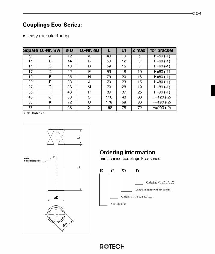
L1L
øD
SW
C 2-4
Couplings Eco-Series:
• easy manufacturing
roterStellungsanzeiger
Ordering informationunmachined couplings Eco-series
K C 59 D
Ordering-No øD : A...X
Length in mm (without square)
Ordering-No Square: A...L
K = Coupling
Square O.-Nr. SW ø D O.-Nr. øD L L1 Z max* for bracket9 A 12 A 49 10 5 H=50 (-1)11 B 14 B 59 12 5 H=60 (-1)14 C 18 D 59 15 6 H=60 (-1)17 D 22 F 59 18 10 H=60 (-1)19 E 25 H 79 20 13 H=80 (-1)22 F 28 J 79 23 15 H=80 (-1)27 G 36 M 79 28 19 H=80 (-1)36 H 48 P 89 37 25 H=90 (-1)46 J 60 S 118 48 30 H=120 (-2)55 K 72 U 178 58 36 H=180 (-2)75 L 98 X 198 78 72 H=200 (-2)
B.-Nr.: Order Nr.

P
SW
F
SW
25 +0,1 Z
37,98Ø ZR
Ø D
79-0
,5
24+
0,5
L
T
Valve Connection By Double D-Drive
Double-D with locating ringThe dimensions of the valve connectionfor flat connectors can be calculated bythe given dimensions of the valve shaft:
High double-D drive:
T = H2 - 1
Locating ring:
øZR = ød + 0,5
Coupling length:
L = L (rough coupling) - H1
H1
H2
Z
ød
C 2-5
Drive dimensions:
Flanschebene

C 2-6
K F 59 N 18 18 F 25
ølocating ring (in mm)
axis position valve/actuatorF = 45°P = parallel
Double-D length (in mm)
Double-D width (in mm)
Ordering Nr. Ø: A...Z (see page C2-3)
Length in mm (without square)
Ordering Nr. SW: A...L (see page C2-3)
K = Coupling
Ordering informationmachined for valve connection Double-D

Valve connection by square drive
P
SW
F SW
45Ø D
-0,5
+0,
5
27 VK
T
L
Vierkant – AnschlußThe dimensions of the valveconnection for square connectorscan be calculated by the given di-mensions of the valve shaft:
High square drive:
T = H2 - 1
Coupling length:
L = L (rough coupling) - H1
H1
H2
Øe
VK
Drive dimensions:
Flanschebene
C 2-7
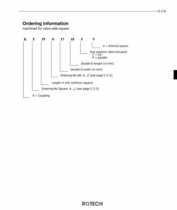
C 2-8
K F 59 N 17 18 F V
V = Internal square
Axis position valve/actuatorF = 45°P = parallel
Double-D length (in mm)
Double-D width (in mm)
Ordering-No øD: A...Z (see page C 2-3)
Length in mm (without square)
Ordering-No Square: A...L (see page C 2-3)
K = Coupling
Ordering informationmachined for valve-side square

ADVANTAGES
Adapter or reduction sleeves are used to adapt the in-ternal square of the actuator shaft to the externalsquare of the coupling or the valve.
Additional dimensions upon request.
• flexibility in choice of the actuators byusing one actuator for different cou-plings,
• single- and double-acting actuatorsare used with the same adapter slee-ves.
Adapter Sleeves
L
+0,1
-0,1
SW2
SW
1
e1-0
,2
e2+0
,2
ABMESSUNGEN:
C 3-1
Square1 Square2 e1 e2 Length L11 9 14 12,1 11
10 13,114 11 18 14,1 14
12 16,117 12 22 16,1 17
14 18,122 17 28 22,2 2227 22 36 28,2 27
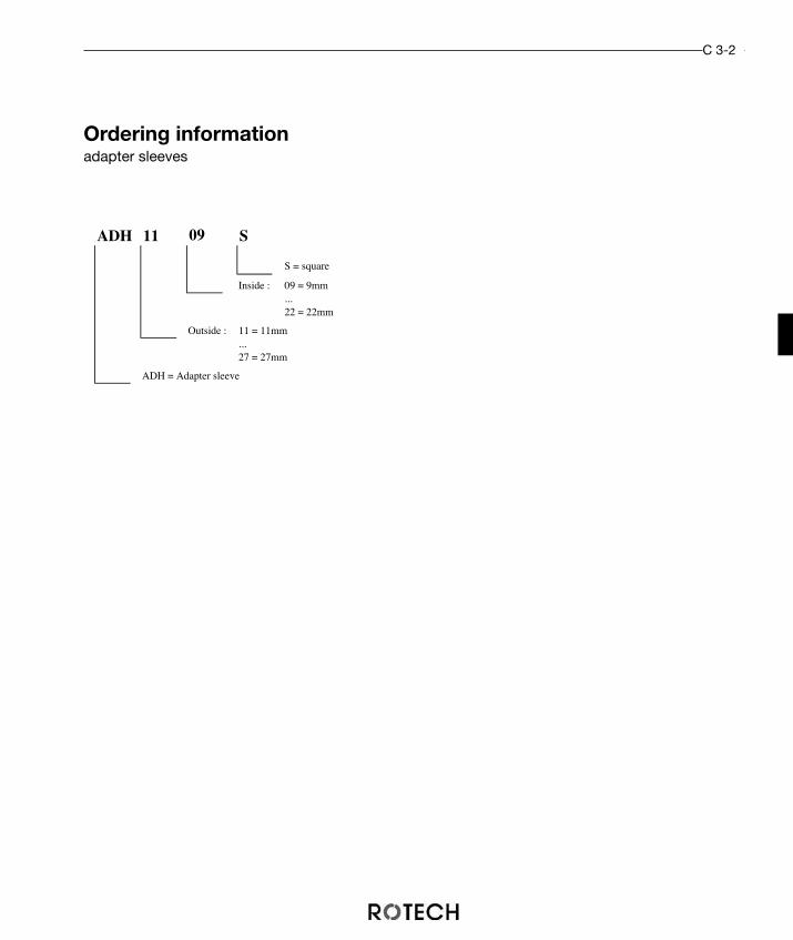
C 3-2
Ordering informationadapter sleeves
ADH 11 09. S
S = square
Inside : 09 = 9mm...22 = 22mm
Outside : 11 = 11mm...27 = 27mm
ADH = Adapter sleeve

Additional dimensions upon request.
Adapter platesfor different flanges
DIMENSIONS:
C 4-1
H
ød
øD
AP F07 F05 10
Height
Flange actuator
Flange valve
AP = Adapter-plate flange
Flange Flange Hight øD ød Ordering-
Valve Actuator H number
10 APF07F0410
11 APF07F0411
25 APF07F0425
10 APF07F0510
11 APF07F0511
20 APF07F0520
F12 F07 18 153 55 APF12F0718
F05 F07 31,5 90 35 APF05F0731A
8 APF07F1008
10 APF07F1010
12 APF07F1012
15 APF07F1015
11 APF10F1411
20 APF10F1420F10 F14 180 80
F07 F10 130 55
90
90
25
35
F07
F07
F04
F05
Ordering informationAdapter plates
Material:Aluminium
You can use adapter plates toconnect valves and actuators withdifferent flanges. The drive shafts ofthe actuator and the valve have tobe compatible.You can mount the plate via hexa-gon socket screws acc. DIN 7984onto the actuator and via insidethread onto the valve.

C 4-2
Connection Flange Platesfor equal flanges
Additional dimensions upon request.
DIMENSIONS:
Flange Height H øD ød Material Order.-Nr.
4 65 35 Al ZPF0504
10 ZPF0510
12 ZPF0512
16 ZPF0516
4 ZPF0704
10 ZPF0710
12 ZPF0712
4 ZPF1004
10 ZPF1010
4 ZPF1204
5 ZPF1205
10 ZPF1210
12 ZPF1212
12 ZPF1412
16 ZPF1416
F05
F07 90 55
F14 100180
F10 130 70
F12 160 85
Al
Al
Al
67 19 Nylon
Al
ZP F07 10Höhe
Flange valve/actuator
ZP = Connection flange
Ordering informaitonConnection Flange Plates
Connection flange plates are used if the shaft of the valve is longer than the retainer onthe actuator. Both flanges have to be identical.
H
ød
øD
H
ød
øD
Werkstoff: Aluminium Werkstoff: Nylon

D 1-1

Direct mounted magnetic solenoid valvesaccording to VDI/VDE 3845 are commonlyused to control pneumatic actuators.Monostable switching functions are usuallypreferred so that in the case of a failure inthe electrical or pneumatic system the con-trol valve will return to a pre-defined positi-on.
Spring return actuators are usually con-trol led by 3/2-way solenoids whiledouble acting actuators are used with4/2- or 5/2-way solenoids.
Magnetic SolenoidsD 1-2
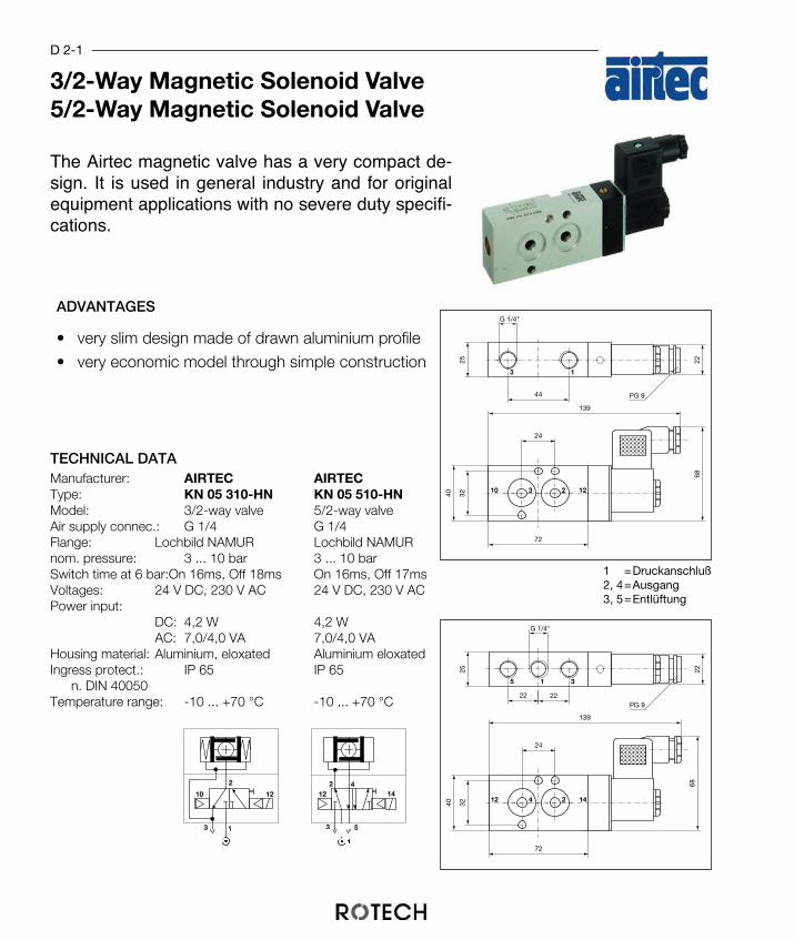
TECHNICAL DATAManufacturer: AIRTEC AIRTECType: KN 05 310-HN KN 05 510-HNModel: 3/2-way valve 5/2-way valveAir supply connec.: G 1/4 G 1/4Flange: Lochbild NAMUR Lochbild NAMURnom. pressure: 3 ... 10 bar 3 ... 10 barSwitch time at 6 bar:On 16ms, Off 18ms On 16ms, Off 17msVoltages: 24 V DC, 230 V AC 24 V DC, 230 V ACPower input:
DC: 4,2 W 4,2 WAC: 7,0/4,0 VA 7,0/4,0 VA
Housing material: Aluminium, eloxated Aluminium eloxatedIngress protect.: IP 65 IP 65
n. DIN 40050Temperature range: -10 ... +70 °C -10 ... +70 °C
42
3 5
1
12 14
3 1
2
1210
3 1
3 2 12 10
24
44
3240
72
139
68
25 22
PG 9
13G 1/4"
3 1 5
4 2 14 12
24
22 22
3240
72
139
68
25 22PG 9
13G 1/4"
3/2-Way Magnetic Solenoid Valve5/2-Way Magnetic Solenoid Valve
D 2-1
ADVANTAGES
• very slim design made of drawn aluminium profile• very economic model through simple construction
The Airtec magnetic valve has a very compact de-sign. It is used in general industry and for originalequipment applications with no severe duty specifi-cations.
1 =Druckanschluß2, 4=Ausgang3, 5=Entlüftung
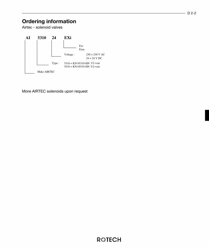
Ordering informationAirtec - solenoid valves
More AIRTEC solenoids upon request
AI 5310 24 EXi
ExiExm
Type : 3/2-voie5/2-voie
24 = 24 V DC
5310 = KN 05310-HN5510 = KN 05510-HN
Make AIRTEC
Voltage : 230 = 230 V AC
D 2-2

TECHNICAL DATA
Manufacturer: Festo FestoType: MFH-3-1/4 NA MFH-5-1/4 NAModel: 3/2-way valve 5/2-way valveAir supply conn.: G 1/4 G 1/4Flanges: NAMUR acc. to DIN VDI/VDE3845nom. pressure: 1,5 ... 8 bar 2,2 ... 8 barSwitch time at 6 bar: On 15ms, Off 45ms On 10ms, Off 42msVoltages: 12 / 24 V DC 12 / 24 V DC
220 V AC 220 V ACPower input:
DC: 4,5 W 4,5 WAC: 6 / 7,5 VA 6 / 7,5 VA
Housing material: Aluminium, oxidized Aluminium, oxidizedIngress protection: IP 65 IP 65
acc. DIN 40050Temperature range: -5 ... +40 °C -5 ... +40 °C
3/2 - Way Solenoid Valves5/2 - Way Solenoid Valves
D 3-1
ADVANTAGES
• light weight aluminium body• excellent speed control through regulation of air ex-
haust
Festo, as a market lieader in pneumatic controlvalves is commonly used in mechanical enginee-ring as well as in many other industrial branches.
42
3 5
1
12
3 1
210
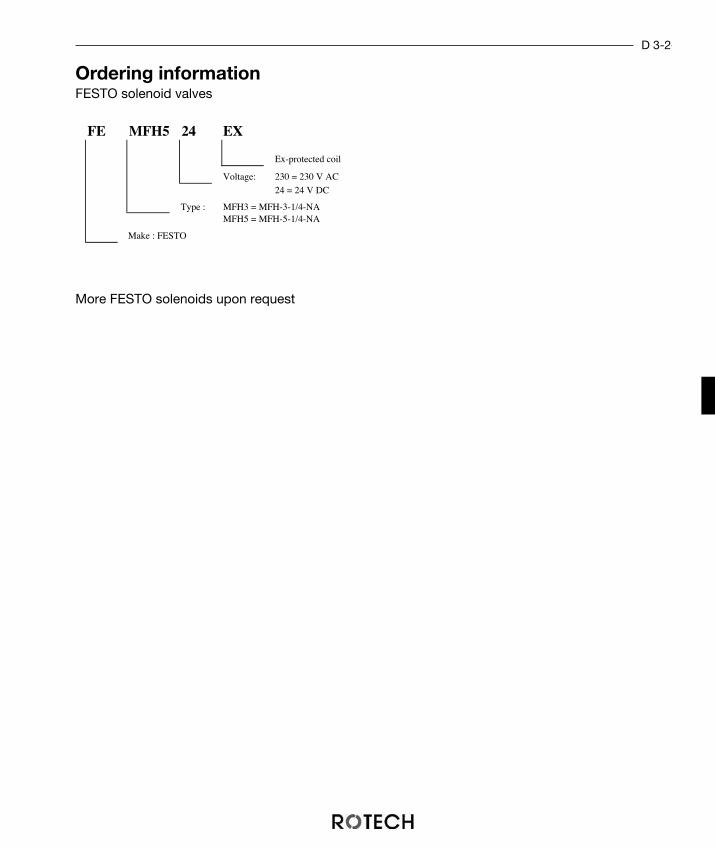
D 3-2
Ordering informationFESTO solenoid valves
More FESTO solenoids upon request
FE MFH5 24 EX
Ex-protected coil
Voltage: 230 = 230 V AC
24 = 24 V DC
Type : MFH3 = MFH-3-1/4-NAMFH5 = MFH-5-1/4-NA
Make : FESTO

D 4-1

Herion – Solenoids
The Herion-magnetic solenoid is a standard solenoid in thechemical and petrochemical industry.
ADVANTAGES
• suitable for almost all applications because of a large va-riety of coils
• the springs of the actuator cannot corrode because thespring area of the 3/2-way solenoid is filled with controlair
• can be applied without problems outdoors because theair exhaust is closed in the unused state. So the innerparts of the solenoid cannot condense and freeze.
D 4-2
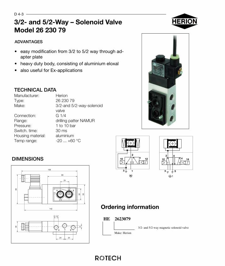
DIMENSIONS
TECHNICAL DATAManufacturer: HerionType: 26 230 79Make: 3/2-and 5/2-way-solenoid
valveConnection: G 1/4Flange: drilling patter NAMURPressure: 1 to 10 barSwitch. time: 30 msHousing material: aluminiumTemp range: -20 ... +60 °C
3 1
2
1210
3/2- and 5/2-Way – Solenoid ValveModel 26 230 79
D 4-3
ADVANTAGES
• easy modification from 3/2 to 5/2 way through ad-apter plate
• heavy duty body, consisting of aluminium eloxal
• also useful for Ex-applications
HE 2623079
3/2- and 5/2-way magnetic solenoid valve
Make: Herion
Ordering information
42
3 5
1
12 14
3
142
156
83
55
5
13
30
G 1/4"
83
5
24 24
1
2 4
24
32

Ordering information
Magnetic Coils
Electrical operated coils for EX-purposesTECHNICAL DATAManufacturer: Herion HerionType: 3062 3063Ingress protection: EEx m IIC T5 EEx m IIC T5
n. EN 50014Nom. power: 2,7 W 2,7 VABetriebsspannung: 24 V DC 230 V ACSchutzart: IP 65 IP 65
n. DIN 40050Temperature range: -20 ... +50 °C -20 ... +50 °C
ADVANTAGES • easy to change by simply opening a screw
• all voltages
• to be used for all valves of these series
Electrical operated coils for Non-EXNon-EX-purposesTECHNICAL DATAManufacturer: Herion HerionType: 3036-24 3036-230Connection: plug acc. to DIN 43650, Form ANom. power: 1,6 W 3,5 VAVoltage: 24 V DC 230 V ACProtection class: IP 65 IP 65
acc to DIN 40050Temp. range: -15 ... +50 °C -15 ... +50 °C
HE 3062 24 EX
Protection class EEx m IIC T5 ( for 3062 and 3063)
Voltage: 24 = 24 V DC230 = 230 V AC
Type : 303630623063
Make : Herion
D 4-4
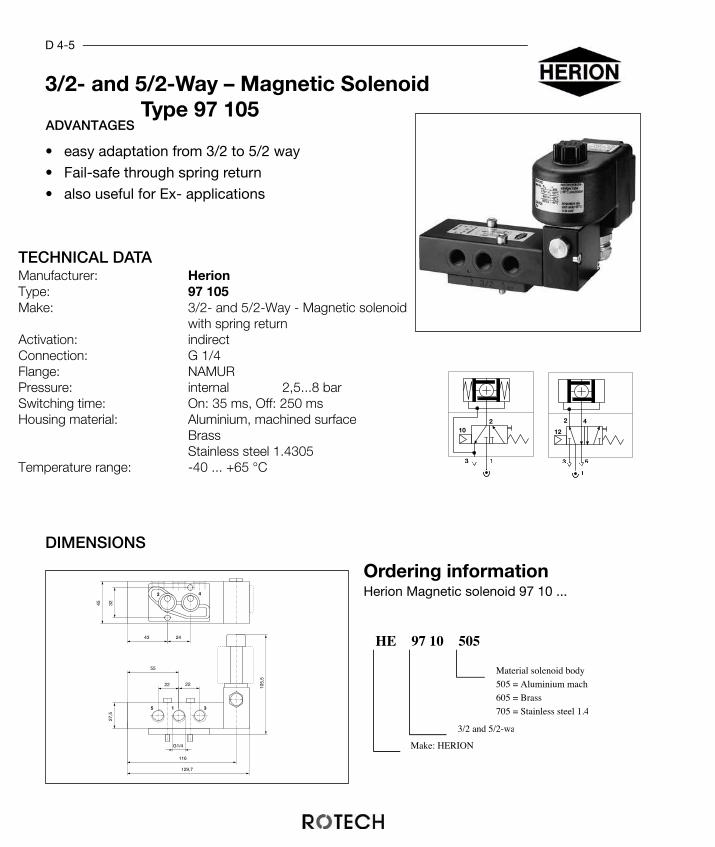
TECHNICAL DATAManufacturer: HerionType: 97 105Make: 3/2- and 5/2-Way - Magnetic solenoid
with spring returnActivation: indirectConnection: G 1/4Flange: NAMURPressure: internal 2,5...8 barSwitching time: On: 35 ms, Off: 250 msHousing material: Aluminium, machined surface
BrassStainless steel 1.4305
Temperature range: -40 ... +65 °C
Ordering informationHerion Magnetic solenoid 97 10 ...
HE 505
705 = Stainless steel 1.4
3/2 and 5/2-wa
Make: HERION
97 10
Material solenoid body
505 = Aluminium machi
605 = Brass
DIMENSIONS
G1/4
1 35
2 4
22 22
55
43 24
3245
27,5
105,
5
116
129,7
D 4-5
3/2- and 5/2-Way – Magnetic SolenoidType 97 105
ADVANTAGES
• easy adaptation from 3/2 to 5/2 way
• Fail-safe through spring return
• also useful for Ex- applications
3 1
210
42
3 5
1
12

D 4-6
Ordering information
Magnetic Coils
Electrical operated coils for EX- applicationsTECHNICAL DATAManufacturer: Herion Herion HerionType: 4200 4201 2050 ... 2053
Protection class: EEx me IIC T5/T6 EEx me IIC T4/T6 EEx ia IIC T6acc. EN 50014
Nom. voltage: 0,7 W 1,3 VAWorking voltage: 24 V DC 230 V AC 24 V DCIngress protection: IP 65 IP 65 IP 65
acc. DIN 40050Temperature range: -40...+80°C (T5) -40...+80°C (T4) -40...+65°C
-40...+70°C (T6) -40...+55°C (T6)
ADVANTAGES • the coils can be easily changed by opening a milled screw
• adjustable to all voltages
• all solenoids of this type can be used because of the same diameter ofthe shaft
Electrical operated coils for NON-EX- applicationsTECHNICAL DATAManufacturer: Herion HerionType: 0253-24 0253-230Plug form: cubical plug acc. cubical plug acc.
DIN 43650, Form A DIN 43650, Form ANom. power: 1,6 W 3,5 VANom. voltage: 24 V DC 230 V ACIngress protection: IP 65 IP 65
acc. DIN 40050Temperature range: -25 ... +60 °C -25 ... +60 °C
HE 4200 24 EX
Protection class:without (0253)EEx me (4200 and 4201)EEx ia (2050...2053)
Voltage: 24 = 24 V DC230 = 230 V AC
Type : 0253420042012300
Make : Herion

D 4-7
TECHNICAL DATAManufacturer: HerionType: 97 100Make: 3/2-und 5/2-Wege-Magnet
ventil mit FerderrückstellungActivation: indirectConnection: G 1/4Deaeration con.: G 1/8Flange: NAMURPressure: 2,5 bis 8 barSwitching time: On: 30 ms Off: 200 msHousing material: Aluminium eloxatedTemperature range: -25 ... +65 °C
3/2- and 5/2-Way – Magnetic SolenoidType 97 100ADVANTAGES
• easy modification from 3/2 to 5/2 way through ad-apter plate
• heavy duty body, consisting of aluminium eloxal
• also useful for Ex- applications
HE 97 100 00Design : 00 = Standard
02 = EEx ia
3/2- and 5/2-way solenoid
Make: Herion
Ordering informationG1/4
G1/8
32 4025
7,2
24,424
38,5
1818
131,7
1
2
3
4
5
3 1
210
42
3 5
1
12

Electricaloperated coils for NON-EX-applicationsTECHNICAL DATAManufacturer: Herion HerionType: 3036-24 3036-230Connection: cubical plug acc. cubical plug acc.
DIN 43650, Form A DIN 43650, Form ANom. voltage: 1,6 W 3,5 VAVoltage: 24 V DC 230 V ACIngress protection: IP 65 IP 65
n. DIN 40050Temperature range: -20 ... +50 °C -20 ... +50 °C
Electrical operated coils for EX-applicationsTECHNICAL DATAManufacturer: Herion Herion HerionType: 3062 3063 3039
Protechtion class: EEx m IIC T5 EEx m IIC T5 EEx ia IIC T6acc. EN 50014
Nom. voltage: 2,7 W 2,7 VAVoltage: 24 V DC 230 V AC 24 V DCSchutzart: IP 65 IP 65 IP 65
n. DIN 40050Temperature range: -20...+50°C -20...+50°C -15...+50°C
D 4-8
Ordering information
Magnetic CoilsADVANTAGES • easy to change by simply opening a screw
• adjustable to all voltages
HE 3062 24 EX
Protection class:EEx m IIC T5 (for 3062 and 3063)EEx ia IIC T6 (for 3039)
Voltage : 24 = 24 V DC230 = 230 V AC
Type : 3036306230633039
Make : Herion

TECHNICAL DATAManufacturer: Samsomatic Samsomatic SamsomaticType: 3963-13... 3963-03... 3963-21...Working voltage: 24 V DC EEx i 24 V DC 230 V ACMake: 3/2-way or 3/2-way or 3/2-way or
5/2-way 5/2-way 5/2-waykvs: 0,16 0,16 0,16Flange: NAMUR NAMUR NAMURWorking pressure: 1,5 ... 8 bar 1,5 ... 8 bar 1,5 ... 8 barHousing material: Trogamid Trogamid TrogamidProtection class: IP 54 or IP 65 IP 54 or IP 65 P 54 or IP 65
n. DIN 40050Temperature range: -25...+80° C -25...+80° C -25...+80° CElectrical connection: M20x1,5 blue M20x1,5 black M20x1,5 blackConnection: G 1/4 G 1/4 G 1/4Manual control: button button button
3/2-way-magnetic solenoid5/2-way magnetic solenoid
D 5-1
ADVANTAGES
• high operational reliability • easy adjustment through 100% adjustable dea-
eration connections• available with or without manual override
SAMSON magnetic solenoids are used tocontrol single- or doubleacting pneumtic ac-tuators by using intrinsically safe signals orelectrical control systems without additionalsignal amplification.
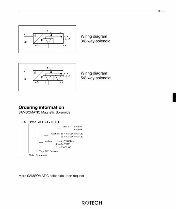
SA 3963 -03 21 - 001 1Prot. class: 1 = IP54
5 = IP65
Function: 11 = 5/2-way NAMUR21 = 3/2-way NAMUR
Voltage : 13 = 24 V DC EEx i03 = 24 V DC21 = 230 V AC
Type 3963 Solenoid
Make : Samsomatic
D 5-2
Ordering informationSAMSOMATIC Magnetic Solenoids
More SAMSOMATIC solenoids upon request
EP
9
4
82
81
1.3 2.3
EP
9
4
82
81
1.3 2.3
Wiring diagram3/2-way-solenoid
Wiring diagram5/2-wqy-solenoidl

D 6-1
2
3 1
12
2
5 1
14
4
3
3/2-way-solenoid valve5/2-way-solenoid valve
ADVANTAGES
• available with your own logo• Adjustable speed through air regulating connec-
tions• extremely compact design
This magnetic solenoid offers a extremelycompact design and is available with yourown logo at higher number of pieces.
TECHNICAL DETAILSSOLENOID
Make: 3/2-way 5/2-waynominal width: 5 mm 5 mmConnection: G 1/4 G 1/4Flange: NAMUR NAMURPressure: 1,5 ... 10 bar 1,5 ... 10 barSwitching time at 6 bar: On 14ms, Off 18ms On 14ms, Off 18msnominal air flow: 660 l/min 660 l/minVoltage: 24 V DC, 230 V AC 24 V DC, 230 V AC
DC:4,2 W 4,2 WAC:7,0/4,0 VA 7,0/4,0 VA
Material housing: aluminium eloxated aluminium eloxatedProtection class: IP 65 IP 65acc. DIN 40050
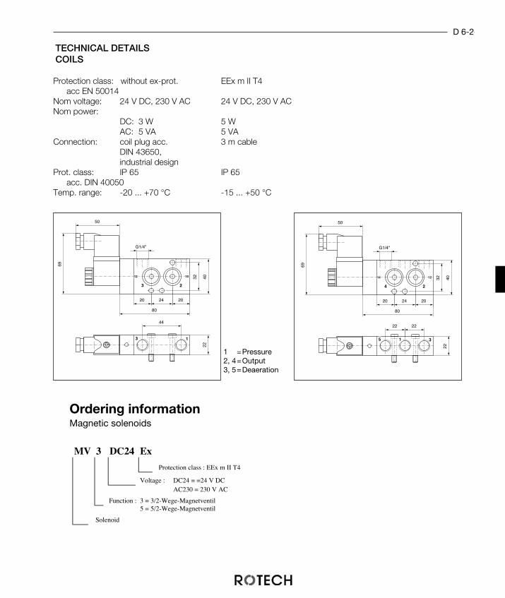
D 6-2
MV 3 DC24 Ex
Protection class : EEx m II T4
Voltage : DC24 = =24 V DCAC230 = 230 V AC
Function : 3 = 3/2-Wege-Magnetventil5 = 5/2-Wege-Magnetventil
Solenoid
Ordering informationMagnetic solenoids
3
2
1
3
12 10
44
22
202420
G1/4"
32 40
80
50
69
5
2
3
4
14 12
22
22
202420
G1/4"
32 40
80
50
69
1
22
TECHNICAL DETAILSCOILS
Protection class: without ex-prot. EEx m II T4acc EN 50014
Nom voltage: 24 V DC, 230 V AC 24 V DC, 230 V ACNom power:
DC: 3 W 5 WAC: 5 VA 5 VA
Connection: coil plug acc. 3 m cableDIN 43650, industrial design
Prot. class: IP 65 IP 65acc. DIN 40050
Temp. range: -20 ... +70 °C -15 ... +50 °C
1 =Pressure2, 4=Output3, 5=Deaeration
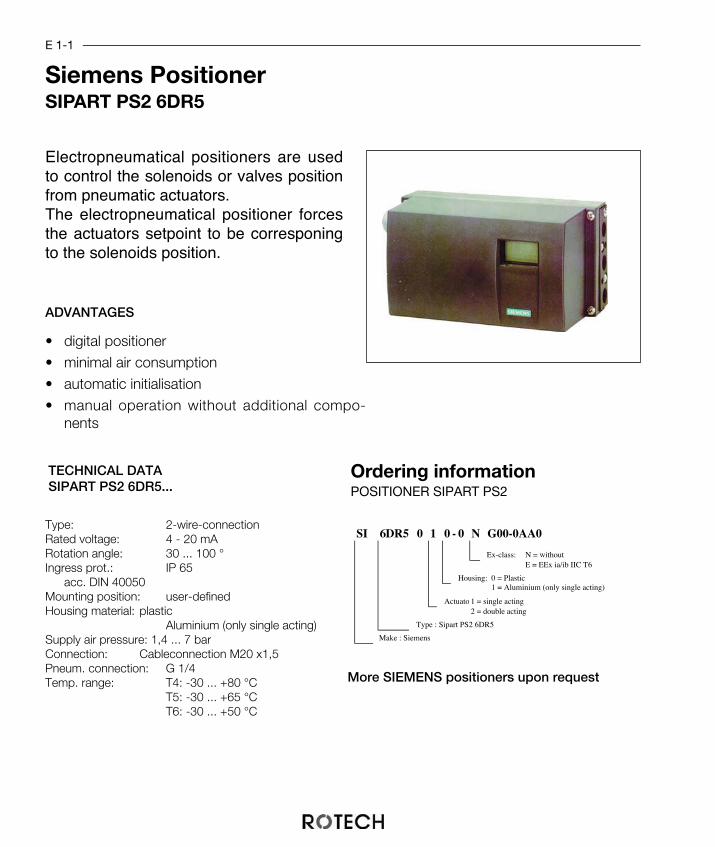
Siemens PositionerSIPART PS2 6DR5
E 1-1
Electropneumatical positioners are usedto control the solenoids or valves positionfrom pneumatic actuators. The electropneumatical positioner forcesthe actuators setpoint to be corresponingto the solenoids position.
ADVANTAGES
• digital positioner• minimal air consumption• automatic initialisation • manual operation without additional compo-
nents
TECHNICAL DATASIPART PS2 6DR5...
More SIEMENS positioners upon request
Type: 2-wire-connectionRated voltage: 4 - 20 mARotation angle: 30 ... 100 °Ingress prot.: IP 65
acc. DIN 40050Mounting position: user-definedHousing material: plastic
Aluminium (only single acting)Supply air pressure: 1,4 ... 7 barConnection: Cableconnection M20 x1,5Pneum. connection: G 1/4Temp. range: T4: -30 ... +80 °C
T5: -30 ... +65 °CT6: -30 ... +50 °C
SI 6DR5 0 1 0 - 0 N G00-0AA0
Ex-class: N = withoutE = EEx ia/ib IIC T6
Housing: 0 = Plastic1 = Aluminium (only single acting)
Actuator1 = single acting2 = double acting
Type : Sipart PS2 6DR5
Make : Siemens
Ordering informationPOSITIONER SIPART PS2

Accessories for positioner SIPART PS2
E 1-2
Adapter kit for valve actuator6DR4004-8D for actuators acc. VDI/VDE 3845.Please specify actuator size VDI/VDE 3845 ororder bracket see chapter A5)
Order number:Mounting kit: SI 6DR448Dandbracket: chapter A5
Optional limit monitor6DR4004-8G (without Ex-prot.) and 6DR4004-6G (EEx ia/ic IIc T4/T5/T6) with two slotted sensors SJ2-SN, 2-wire acc.DIN 19 234 (NAMUR)
Order number:without Ex-prot.: SI 6DR448GEEx ia/ib IIC: SI 6DR446G
Alarmmodul6DR4004-8A (without Ex-prot.) and 6DR4004-6A (EEx ia/ic IIc T4/T5/T6) with two limit monitors, one failure detector andone binary input
Order number:without Ex-prot.: SI 6DR448AEEx ia/ib IIC: SI 6DR446A
Manometerblock6DR4004-1M for single acting positioner withtwo pressure gauges and 6DR4004-2M for double acting positioner withthree pressure gauges
Order number:single acting: SI 6DR441Mdouble acting: SI 6DR442M

E 2-1
Samson PositionerTyp 3767
Electropneumatical positioners are usedto control the solenoids or valves positionfrom pneumatic actuators. The electropneumatical positioner forcesthe actuators setpoint to be corresponingto the solenoids position.
ADVANTAGES
• minimal emergency current consumption• minimal vibration effect• compact, low maintenance design
TECHNICAL DATASamson 3767
Function: single actingType: 2-wire-connectionRated voltage: 4 - 20 mARotation angle: 90 °Ingress protection: IP 54
acc. DIN 40050Mounting position: user-definedHousing material: AluminiumSupply air pressure:1,4 ... 6 barConnection: Cableconnection M20 x1,5Pneum. connection: G 1/4Temperature range: -20 ... + 80°C
Options: Proximity sensors(upon request) Manometerblock
Security solenoid
Ordering informationPOSITIONER SAMSON 3767
More Samson positioners upon request
SA 3767 - 0 0 0 0 2 2 2 00 1
Cable connection: 1 = blue2 = black
Field of view 2: full signal
Proximity switch: 0 = without2 = 2 x SJ2-SN
Ex-class: 0 = without1 = EEx ia IIC T6
Type : 3767
Make : Samson
E 2-2
Adapter kit for valve actuatorAdapter kit for actuators acc. VDI/VDE 3845.Please specify actuator size VDI/VDE 3845 ororder bracket see chapter A5)
Order number:Adapter kit: SA ABT 3845andbracket: chapter A5
Reversal amplifier for double acting ac-tuators For double acting actuators a additional pneu-matic reversal amplifier is needed to create se-cond counterrotating pressure.
Order number:Reversal amplifier: SA UKV 1079
Accessories for positioner Samson 3767

Silencers
Round Type Flat Type
AccessoriesF 1-1
G
L
H
SW
Silencers are used to reduce the noise of the exhaust air. They are sintered, the materi-al being nickeled brass. two types are available, round and flat type for minimum di-mensions.
G
LH
SW
G Square H L1/8" 12 4 4,51/4" 15 4,5 63/8" 19 5,5 71/2" 23 6 8
G Square H L1/8" 12 8 4,51/4" 15 11 63/8" 19 15 71/2" 23 17 8
SCHD 14 KBR
Shape : KBR = short, roundKBF = short, flat
Connection : 18 = G1/814 = G1/438 = G3/812 = G1/2
Silencer
Ordering informationSilencers
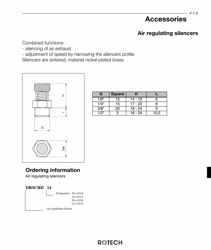
Combined functions:- silencing of air exhaust - adjustment of speed by narrowing the silencers profileSilencers are sintered, material nickel-plated brass
Ordering informationAir regulating silencers
Air regulating silencers
AccessoriesF 1-2
G Square H L1/8" 12 14 - 19 61/4" 15 17 - 22 83/8" 20 18 - 24 91/2" 2 18 - 24 10,5
DRSCHD 14Connection : 18 = G1/8
14 = G1/438 = G3/812 = G1/2
Air regulating silencer
G
LH
SW
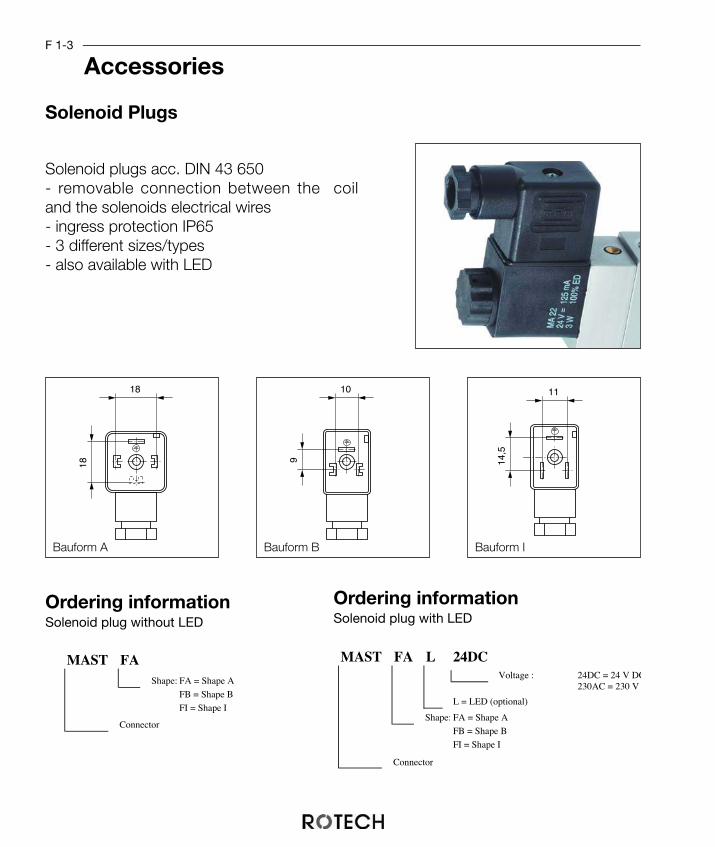
Solenoid Plugs
AccessoriesF 1-3
Solenoid plugs acc. DIN 43 650- removable connection between the coiland the solenoids electrical wires- ingress protection IP65- 3 different sizes/types- also available with LED
18
18
10
9
11
14,5
MAST FA L 24DCVoltage : 24DC = 24 V DC
230AC = 230 V
L = LED (optional)
Shape: FA = Shape A
FB = Shape B
FI = Shape I
Connector
Bauform A Bauform B Bauform I
MAST FAShape: FA = Shape A
FB = Shape B
FI = Shape I
Connector
Ordering informationSolenoid plug without LED
Ordering informationSolenoid plug with LED
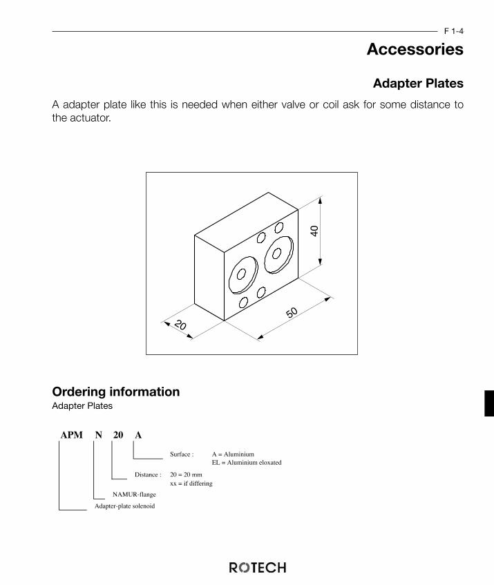
Adapter Plates
AccessoriesF 1-4
4050
20
A adapter plate like this is needed when either valve or coil ask for some distance tothe actuator.
Ordering informationAdapter Plates
APM N 20 A
Surface : A = AluminiumEL = Aluminium eloxated
Distance : 20 = 20 mmxx = if differing
NAMUR-flange
Adapter-plate solenoid
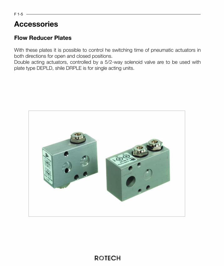
Flow Reducer Plates
AccessoriesF 1-5
With these plates it is possible to control he switching time of pneumatic actuators inboth directions for open and closed positions.Double acting actuators, controlled by a 5/2-way solenoid valve are to be used withplate type DEPLD, shile DRPLE is for single acting units.

DRPL EE = spring returnD = double acting
Flow reducer plate
4025
6075
4030
Ordering informationFlow Reducing Plates
Flow Reducing Platesdouble acting
Flow Reducing Platesingle acting
F 1-6
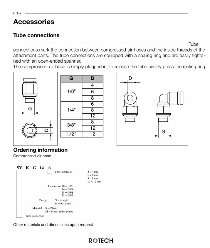
Tubeconnections mark the connection between compressed-air hoses and the inside threads of theattachment parts. The tube connections are equipped with a sealing ring and are easily tighte-ned with an open-ended spanner.The compressed-air hose is simply plugged in, to release the tube simply press the realing ring
Ordering informationCompressed-air hose
Other materials and dimensions upon request
Tube connections
AccessoriesF 1-7
G
D G
DG D4686812812
1/2" 12
3/8"
1/4"
1/8"
SV K G 14 6Tube-outside ø 4 = 4 mm
6 = 6 mm8 = 8 mm12 = 12 mm
Connection 18 = G1/814 = G1/438 = G3/812 = G1/2
Design : G = straightW = 90° offset
Material : K = PlasticM = Brass, nickel-plated
Tube connection

Compressed-Air Hose
AccessoriesF 1-8
Flexible compressed-air hoses (material: Polyurethan) are abrasion-resistant, compression proof and wear restistant. They are ideal to connect actuators with positioners or solenoids.
Ordering informationCompressed-air hose
Other materials and dimensions upon request
Working pressure:-35 ... +30 °C: 10 bar+30 ... +60°C: 7 bar
ød
øD
DLS PU 6 BL
Color :BL = blueSW = black
Inside ø : 3 = 3 mm4 = 4 mm6 = 6 mm8 = 8 mm
Material: Polyurethan
Compressed-air hose
Order.-Nr. ød øDDLSPU3 3 4DLSPU4 4 6DLSPU6 6 8DLSPU8 8 12

Manual Emergency Gears
AccessoriesF 2-1
Manual emergency gears are used to manually control valves with mounted on actua-tors. The gear offers a top and bottom flange and can be mounted between valve andactuator.In normal mode the wormgear is disengaged from the connection. The movement ofthe actuator is copied through a coupling to the valves shaft. To activate the emergen-cy function, sway the lever and fix it to the gear.The self-hemming gear can be brought to every wished position.
To dimension the gear for single acting actuators please consider the max. elastic forceof the actuator and the max. torque of the valve.
MA V / F12 27 / R14
ø handwheel
Square
Flange
Type : X = MXWDZ = MZWDV = MVWDA = MAWD
C = MCWD
Make : Mastergear
Ordering informationHandnotgetriebe
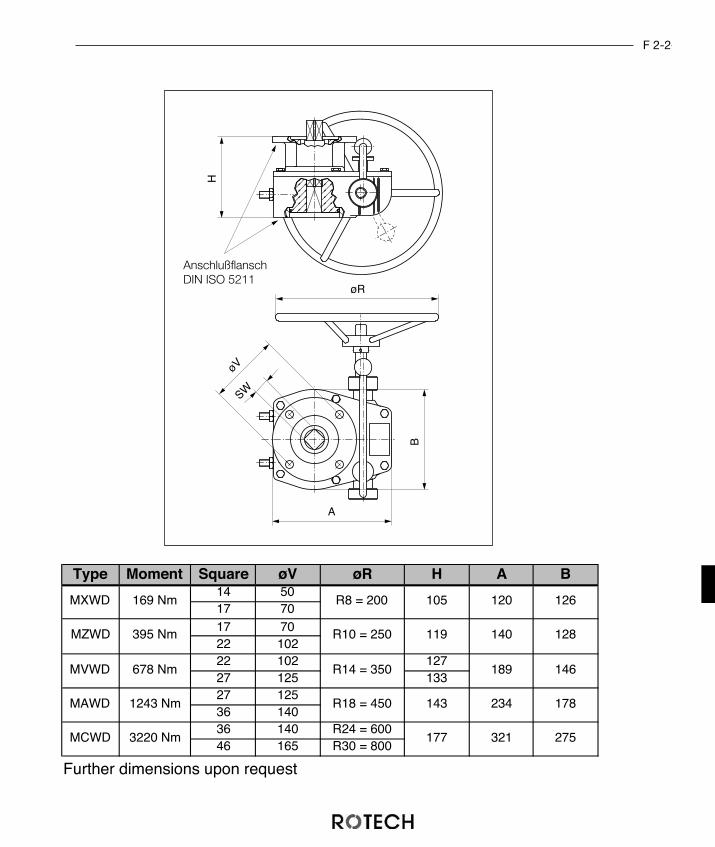
H
øR
B
A
øV
SW
Type Moment Square øV øR H A B14 5017 7017 7022 10222 102 12727 125 13327 12536 14036 140 R24 = 60046 165 R30 = 800
275
178
146
128
143
177
R18 = 450
140
189
234
321MCWD 3220 Nm
R10 = 250
R14 = 350MVWD 678 Nm
MAWD 1243 Nm
120 126
MZWD 395 Nm 119
MXWD 169 Nm R8 = 200 105
Further dimensions upon request
F 2-2
AnschlußflanschDIN ISO 5211

MONT HNG V
Type : X = MXWDZ = MZWDV = MVWD
A = MAWDC = MCWD
for manual override
Mounting set for deaeration
Ordering informationMounting kit for forced deaeration
Forced deaeration for manual emergency gears
Accessories
To ensure that the actuator is totally deaerated during a manual switching operation,and to avoid that the actuator will be filled with air again, it is possible to mount a stop-valve to the gear.
42
3 51
12
1
2
3
2
10
1
2
3
3 1
F 2-3

F 2-4
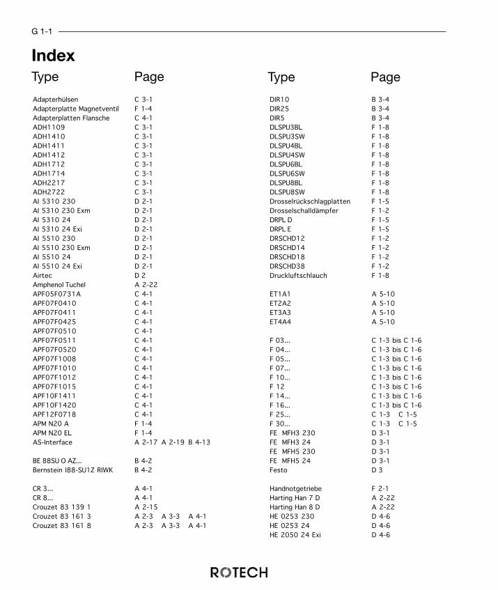
G 1-1
Index
Adapterhülsen C 3-1Adapterplatte Magnetventil F 1-4Adapterplatten Flansche C 4-1ADH1109 C 3-1ADH1410 C 3-1ADH1411 C 3-1ADH1412 C 3-1ADH1712 C 3-1ADH1714 C 3-1ADH2217 C 3-1ADH2722 C 3-1AI 5310 230 D 2-1AI 5310 230 Exm D 2-1AI 5310 24 D 2-1AI 5310 24 Exi D 2-1AI 5510 230 D 2-1AI 5510 230 Exm D 2-1AI 5510 24 D 2-1AI 5510 24 Exi D 2-1Airtec D 2Amphenol Tuchel A 2-22APF05F0731A C 4-1APF07F0410 C 4-1APF07F0411 C 4-1APF07F0425 C 4-1APF07F0510 C 4-1APF07F0511 C 4-1APF07F0520 C 4-1APF07F1008 C 4-1APF07F1010 C 4-1APF07F1012 C 4-1APF07F1015 C 4-1APF10F1411 C 4-1APF10F1420 C 4-1APF12F0718 C 4-1APM N20 A F 1-4APM N20 EL F 1-4AS-Interface A 2-17 A 2-19 B 4-13
BE 88SU O AZ... B 4-2Bernstein I88-SU1Z RIWK B 4-2
CR 3... A 4-1CR 8... A 4-1Crouzet 83 139 1 A 2-15Crouzet 83 161 3 A 2-3 A 3-3 A 4-1Crouzet 83 161 8 A 2-3 A 3-3 A 4-1
DIR10 B 3-4DIR25 B 3-4DIR5 B 3-4DLSPU3BL F 1-8DLSPU3SW F 1-8DLSPU4BL F 1-8DLSPU4SW F 1-8DLSPU6BL F 1-8DLSPU6SW F 1-8DLSPU8BL F 1-8DLSPU8SW F 1-8Drosselrückschlagplatten F 1-5Drosselschalldämpfer F 1-2DRPL D F 1-5DRPL E F 1-5DRSCHD12 F 1-2DRSCHD14 F 1-2DRSCHD18 F 1-2DRSCHD38 F 1-2Druckluftschlauch F 1-8
ET1A1 A 5-10ET2A2 A 5-10ET3A3 A 5-10ET4A4 A 5-10
F 03... C 1-3 bis C 1-6F 04... C 1-3 bis C 1-6F 05... C 1-3 bis C 1-6F 07... C 1-3 bis C 1-6F 10... C 1-3 bis C 1-6F 12 C 1-3 bis C 1-6F 14... C 1-3 bis C 1-6F 16... C 1-3 bis C 1-6F 25... C 1-3 C 1-5F 30... C 1-3 C 1-5FE MFH3 230 D 3-1FE MFH3 24 D 3-1FE MFH5 230 D 3-1FE MFH5 24 D 3-1Festo D 3
Handnotgetriebe F 2-1Harting Han 7 D A 2-22Harting Han 8 D A 2-22HE 0253 230 D 4-6HE 0253 24 D 4-6HE 2050 24 Exi D 4-6
Type Page Type Page

G 1-2
Index
HE 2623079 D 4-3HE 3036 230 D 4-4 D 4-8HE 3036 24 D 4-4 D 4-8HE 3039 24 Exi D 4-8HE 3062 24 Exm D 4-4 D 4-8HE 3063 230 Exm D 4-4 D 4-8HE 4200 24 Exm D 4-6HE 4201 230 Exm D 4-6HE 97 10 505 D 4-5HE 97 10 605 D 4-5HE 97 10 705 D 4-5HE 97 100 00 D 4-7HE 97 100 02 D 4-7Herion D 4HO 14 CE O AZ... B 4-5Honeywell 14 CE 102 B 4-5
IF 5225 O AZ B 4-8IF 5251 O AZ B 4-8IFM IN 5225 B 4-8IFM IN 5251 A 2-5 B 4-8
KA49... C 2-3 C 2-4KB59... C 2-3 C 2-4KC59... C 2-3 C 2-4KD M12 G4 PG9 B 4-12KD M12 W4 PG9 B 4-12KD59... C 2-3 C 2-4KE79... C 2-3 C 2-4KF79... C 2-3 C 2-4KG79... C 2-3 C 2-4KH89... C 2-3 C 2-4KJ118... C 2-3 C 2-4KK178... C 2-3 C 2-4KL198... C 2-3 C 2-4
Lumberg RKF5 A 2-21
M12 A 2-21MAA/F1227/R18 F 2-1MAA/F1436/R18 F 2-1MAC/F1436/R24 F 2-1MAC/F1646/R30 F 2-1Magnetstecker F 1-3Mastergear F 2-1MASTFA F 1-3MASTFAL230AC F 1-3MASTFAL24DC F 1-3
MASTFB F 1-3MASTFBL230AC F 1-3MASTFBL24DC F 1-3MASTFI F 1-3MASTFIL230AC F 1-3MASTFIL24DC F 1-3MAV/F1022/R14 F 2-1MAV/F1227/R14 F 2-1MAX/F0514/R8 F 2-1MAX/F0717/R8 F 2-1MAZ/F0717/R10 F 2-1MAZ/F1022/R10 F 2-1MONT HNG A F 2-2MONT HNG C F 2-2MONT HNG V F 2-2MONT HNG X F 2-2MONT HNG Z F 2-2MV3DC230 D 6-1MV3DC230Ex D 6-1MV3DC24 D 6-1MV3DC24Ex D 6-1MV5DC230 D 6-1MV5DC230Ex D 6-1MV5DC24 D 6-1MV5DC24Ex D 6-1
P+F NBB2-V3-E2 A 2-9P+F NBB2-V3-E2-V5 A 3-9P+F NBN3-F25F-E8 A 2-5 A 3-7 B 4-9P+F NBN3-F25F-E8-P A 3-5P+F NBN3-F25F-E8-V1 A 3-7 B 4-9P+F NBN3-F31-E8-K B 4-13P+F NBN3-F31-E8-K-K B 4-13P+F NBN3-F31K-E8 B 4-14P+F NBN3-F31K-E8-K B 4-14P+F NBN3-F31K-E8-V1-V1 B 4-14P+F NBN4-12GM50-E2 A 2-7 A 4-3P+F NCN3-F25F-N4 A 2-13 A 3-13 B 4-9P+F NCN3-F25F-N4-P A 3-11P+F NCN3-F25F-N8-V1 A 3-13 B 4-9P+F NCN3-F31-B3-V1-K B 4-13P+F NCN3-F31K-N4 B 4-14P+F NCN3-F31K-N4-K B 4-14P+F NCN3-F31K-N4-V1-V1 B 4-14P+F NCN3-F31-N4-K B 4-13P+F NCN3-F31-N4-K-K B 4-13P+F NCN3-F31-N4-V16-V16 B 4-13P+F NJ2-V3-N-V5 A 3-15
Type Page Type Page

G 1-3
Index
P+F SJ3,5-N A 2-11 A 4-5P+F SJ5-N A 2-11 A 4-5PCR 3... A 3-3PCR 8... A 3-3PF 3N... A 4-5PF F25E O AZ... B 4-9PF F25EV O AZ B 4-9PF F25N O AZ... B 4-9PF F25NV O AZ B 4-9PF F31 B K O AZ B 4-13PF F31 E K O AZ... B 4-13PF F31 E KK O AZ... B 4-13PF F31 N K O AZ... B 4-13PF F31 N KK O AZ.. B 4-13PF F31 N VV O AZ... B 4-13PF F31K E K O AZ B 4-14PF F31K E KK O AZ B 4-14PF F31K E O AZ B 4-14PF F31K N K O AZ B 4-14PF F31K N KK O AZ B 4-14PF F31K N O AZ B 4-14PF N412E... A 4-3PPF 2V3E... A 3-9PPF 2V3N... A 3-15PPF F25E K... A 3-7PPF F25E P... A 3-5PPF F25E S... A 3-7PPF F25N K... A 3-13PPF F25N P... A 3-11PPF F25N S... A 3-13
SA 3767-000 0 222 001 E 2-1SA 3767-020 0 222 001 E 2-1SA 3767-100 0 221 001 E 2-1SA 3767-120 0 221 001 E 2-1SA 3963-0311-0011 D 5-1SA 3963-0321-0011 D 5-1SA 3963-1311-0111 D 5-1SA 3963-1321-0111 D 5-1SA 3963-2111-0011 D 5-1SA 3963-2121-0011 D 5-1SA ABT 3845 E 2-2SA UKV 1079 E 2-2Samsomatic D 5Samson 3767 E 2-1SC 236 O AZ.. B 4-2Schalldämpfer F 1-1SCHD 12 KB... F 1-1
SCHD 14 KB... F 1-1SCHD 18 KB... F 1-1SCHD 38 KB... F 1-1Schlauchverschraubungen F 1-7Schmersal ZR 236-11Z B 4-2SI 200 O AZ.. B 4-2SI 6DR4004-1M E 1-2SI 6DR4004-2M E 1-2SI 6DR4004-6A E 1-2SI 6DR4004-6G E 1-2SI 6DR4004-8A E 1-2SI 6DR4004-8D E 1-2SI 6DR4004-8G E 1-2SI 6DR441M E 1-2SI 6DR442M E 1-2SI 6DR446A E 1-2SI 6DR446G E 1-2SI 6DR448A E 1-2SI 6DR448D E 1-2SI 6DR448G E 1-2SI 6DR5010-0EG00-0AA0 E 1-1SI 6DR5010-0NG00-0AA0 E 1-1SI 6DR5011-0EG00-0AA0 E 1-1SI 6DR5011-0NG00-0AA0 E 1-1SI 6DR5020-0EG00-0AA0 E 1-1SI 6DR5020-0NG00-0AA0 E 1-1Siemens 3 SE3 200-1D B 4-2Siemens Sipart PS2 E 1-1SNO101L B 3-2SNO101R B 3-2SNO102L B 3-2SNO102R B 3-2SNO10PB B 3-3SNO5R B 3-2SNOU B 3-3ST E14R O AZ... B 4-5STELAZOA B 3-4STELAZPB B 3-3STELAZTCR B 3-4Steute EX14R B 4-5STKASI A 2-20SVKG12 12 F 1-7SVKG14 12 F 1-7SVKG14 6 F 1-7SVKG14 8 F 1-7SVKG18 4 F 1-7SVKG18 6 F 1-7SVKG18 8 F 1-7S G38 2
Type Page Type Page

G 1-4
Type Page Type PageSVKG38 12 F 1-7SVKG38 8 F 1-7SVKW12 12 F 1-7SVKW14 12 F 1-7SVKW14 6 F 1-7SVKW14 8 F 1-7SVKW18 4 F 1-7SVKW18 6 F 1-7SVKW18 8 F 1-7SVKW38 12 F 1-7SVKW38 8 F 1-7SVMG12 12 F 1-7SVMG14 12 F 1-7SVMG14 6 F 1-7SVMG14 8 F 1-7SVMG18 4 F 1-7SVMG18 6 F 1-7SVMG18 8 F 1-7SVMG38 12 F 1-7SVMG38 8 F 1-7SVMW12 12 F 1-7SVMW14 12 F 1-7SVMW14 6 F 1-7SVMW14 8 F 1-7SVMW18 4 F 1-7SVMW18 6 F 1-7SVMW18 8 F 1-7SVMW38 12 F 1-7SVMW38 8 F 1-7
T CR 1... A 2-15T CR 3... A 2-3T CR 8... A 2-3T IF 5251... A 2-5T PF 2V3E... A 2-9T PF 3N... A 2-11T PF F25E... A 2-5T PF F25N... A 2-13T PF N412E... A 2-7T TU 4DSAP... A 2-5T0A0 A 5-9T1A1 A 5-8T2A2 A 5-8T3A3 A 5-8T4A4 A 5-8TK1A1 A 5-7TK2A2 A 5-7TL3A3 A 5-7
TL4A4 A 5-7TU 4DA O AZ... B 4-11TU 4DAH O AZ... B 4-11TU 4DY O AZ... B 4-11TU 4DYH O AZ... B 4-11Turck Ni4-DS20-2AP6X2 A 2-5 B 4-11Turck Ni4-DS20-2Y0X2 B 4-11Turck Si3,5-K10-Y1 A 2-11Turck Si5-K09-Y1 A 2-11
UBE1 A 5-5UBE23 A 5-6UBE4 A 5-6UBT1 A 5-3UBT23 A 5-4UBT4 A 5-4UNIPLKPL B 2-1
ZPF0504 C 4-2ZPF0510 C 4-2ZPF0512 C 4-2ZPF0516 C 4-2ZPF0704 C 4-2ZPF0710 C 4-2ZPF0712 C 4-2ZPF1004 C 4-2ZPF1010 C 4-2ZPF1204 C 4-2ZPF1205 C 4-2ZPF1210 C 4-2ZPF1212 C 4-2ZPF1412 C 4-2ZPF1416 C 4-2Zwischenflanschplatten C 4-2
Index

This manual was presented to you by: