catalogo flessibili inglese - gts trasmissioni · ing (agma 9000 class 9) execution to api 610 ......
TRANSCRIPT

Pagi a: GTS TRASMISSIONI
GTS TRASMISSIONI

Page: 2 GTS TRASMISSIONI
FLEXIBLE ALL METAL COUPLINGS Introduction The large number of flexible couplings successfully put into service over the past few years indicates an increasing popularity for this type in any application, besides on high power and high speed applications.
It will be shown that, by careful design and choice of material, the power/weight ratio can be increased to meet the low hung weight requirements of current and future design trends in high speed machinery.
Description of the flexible element The flexible elements have driving and driven bolts on a common pitch circle diameter. Drawings A illustrate the continuous ring types; drawing B illustrate the separate link types.
The flexible elements transmit torque uniformly working on the principle of a direct pull between driving and driven bolt, and this will produce a simple tensile stress in the blade. The flexible element transmit torque by a simple tensile force between alternate driving and driven bolts on a common pitch circle diameter and flexibility, which is derived from the span between adjacent bolts, will vary as the cube of the free length. Operational Charateristics In operation the trailing blade will be in tension and the leading blade will be in compression. The applying of an axial force produce an axial deflection y and, in doing this, the free length of the blade will be stretched . It can be shown that, as a first approximation the axial force varies approximately as the cube of deflection. With a force, due to transmitted torque, applied to the driving bolts, the original length of the trailing blade is increased whilst the distance between driving and driven bolts, on the leading side, is less than the free length. As the leading blade is now slack, the trailing blade can be deflected axially without suffering further extension, so that the force required to move the blade axially will be directly proportional to the deflection, and will remain linear until the deflection is sufficient to remove all slack in the leading blade when the distance between driving and driven bolts will be equal to the original free length.
A B B

Page: 3 GTS TRASMISSIONI
A further condition will affect the axial force is the effect of speed. Depending on the physical size of the coupling, the effect of centrifugal force will normally be small at low speed, but may have a very significant effect at high speed. Under condition of high speed there will be increase in bolt pitch circle which can be related to a strain in the blades so that the original length of all blades is increased. Consideration Laminated membrane couplings, however, are not only chosen solely on a consideration of axial thrust, but more frequently on a basis of allowable misalignment. The generated thrust being more commonly a secondary consideration and normally well within the capability of associated thrust bearings. End thrust is present in a gear coupling for a very different reason, having nothing to do with the elastic properties of the material but solely due to the loading on the teeth and the coefficient of friction between then. This thrust, the presence of which is frequently overlooked in gear couplings, can be a major cause of failure in double helical gearboxes. The most likely cause of failure in laminated membrane coupling is bending fatigue of the laminations close to their anchor points, and it is therefore important that the flexible elements should, at all times, work within the limits of allowable fluctuating stress. Stresses due to a torque and pure axial deflection can be considered as steady stress, and those due to angular misalignment as fluctuating. Parallel misalignment applied to a spacer coupling is achieved by causing both elements to tilt. In this sense, parallel shaft misalignment which may exist can, therefore, add to or subtract from the allowable parallel misallignment. Conclusions One of the virtutes of the laminated membrane coupling is its versatility an the ease with which its design can be modified to suit particular requirements.

Page: 4 GTS TRASMISSIONI
Coupling selection The selection of coupling size and type will be dependant on several factors. The first requirement must obviously be to choose a unit of adequate size of transmit the maximum torque and for this purpose it is advisable to use the actual available power of the driving machine rather than the calculated absorbed power of the driven machine, unless this latter is known not be exceeded. Having determined the maximum HP or KW to be transmitted, this is divided by the speed to give the HP or KW/rpm so that, by comparison with the technical data, a selection can be made from any of the various coupling types. If the type of applicationdemands the use of a Service Factor this should be applied before selecting the coupling size. If the resulting specific rating falls between two coupling size, the larger should be selected. The standard coupling will withstand a short circuit torque (C.C.) of 2,5 times the nominal torque. When the C.C. exceeds 2,5 times nominal size the coupling from: HP (KW x 1,36) x 716,2 x 9,81 x C.C. x Service Factor ----------------------------------------------------------------------------------------- rpm x 2,5 x Nominal Torque For direct on line motors, where the starting torque does not exceed 2 x nominal, use a Service Factor of 1,5, unless the Service Factor already applied for the particular application is 1,5 or greater, inwich case no Service Factor need be applied; if the starting torque is greather than 2 x nominal,determine the required size from: HP (KW x 1,36) x 716,2 x 9,81 Max expected torque Nominal Torque = ------------------------------------------- x ---------------------------------- rpm 1,5 x Nominal Torque Having determined the coupling rating, the required flexibility must be considered from an assessment of the shaft movements, comparing these with relative technical data. A final check should be made to ensure that the maximum hub bore dimension is adequate for the shaft. Providing, after the selection is made, other factors such as weight, torsional stiffness etc, as given in the appropriate tables are acceptable then a standard unit can be selected. If not consult our technical department who are always willing to give advice and produce special designs outside the catalogue dimensions if required. It should be noted that, throughout the catalogue, the coupling size indicates its rated capacity in Nm: for instance coupling LSDA 1700-6 is an 6 bolt coupling with a rated capacity of 1700 Nm.
Characteristics No sparking execution No maintenance High torque with low weight Long working life Angular misalignment Parallel misalignment (for spacer range) Axial misalignment (for spacer range) Possibility to adjust the axial stroke (for spacer range) Torsional stiffness shug also with reversal torque Limited axial thrust
Characteristics Complete metallic construction: - Hubs, adapters, spacers : Uni 7845 C45 - Flexible elements : AISI 304 C - Bolts : Uni 5933 10.9 - Possibility of complete ANSI construction No lubrication is required Operation in both directions of rotation Operation in adverse environmental conditions High temperature operation High balancing quality because of precise manufactur-ing (AGMA 9000 Class 9) Execution to API 610 (all standard range LSDA) Execution to API 671 (LSDA range on request)

Page: 5 GTS TRASMISSIONI
SERVICE FACTORS TABLE ( According to Agma 514.02 )
Load classification U Uniform M Medium H High
Service factors
Driving machines: Electric mover Water turbine Piston engines Piston engines Gas turbine 4 - 12 cylinders 1 - 3 cylinders Stream turbine U 1,5 U 2 U 2,5 U 1-3 M 2 M 2,5 M 3 M 3,8 H 3 H 3,5 H 4,5 H 5,5
Driven machines: Special industries applications: Foods Paper Chemical Paking U Centrifugal pumps M Calenders U Agitators H Wrappings M Cane crushers H Wet presses U Centrifuges light H Formings M Bottling filling machines H Pulpers M Agitators semi liquid M Buildings M Kneading machines H Drying cylinders M Centrifuges heavy M Conveyng sistems H Rollers H Palletizers Building Rubber Metal rolling mills Machines tools M Hoists M Calenders M Roller tables light U Auxiliary drivers M Concrete mixers H Extruders M Cooling beds M Main drivers M Road constr.machiner. H Mixers H Cold rolling mills H Crushers H Plate cutters H Billet shears Wood Metal work. Mining Mills U Wood work. machines U Auxil. drivers M Main pumps H Stamping mills M Planing machines M Shears M Travelling gear (Rails) H Driers H Frames M Main drives H Bucket wheels H Grinding mills H Barkers H Presses H Travelling gears H Kilns H Hanners M Manoeuvring M Bendings H Power shovels Plastic Oil industry Textile Laundries Filters M Calanders M Pipeline pumps M batchers H Tumblers U Aerators M Crushers H Rotary drilling M Willows H Washing machines M Rotary filters M Mixers M Looms M Tanning vats printing General applications: Compressors Cranes Pumps Conveyors Fans U Axial centrifugal M Hoist gears U Centrifugal pumps M Apron drag conveyors M Centrifugals M Turbo compressors U Travelling gears H Piston pumps M Hoists H Wind machines H Piston compressors M Slewing gears H Pressure pumps H Belt conveyors H Centrifugal pumps H Inclined hoists semi-liquids H Extraction plants For more specific figures it is recommended that AGMA 514 02 or similar reference should be consulted, or refer-ence made to our Technical Department

Page: 6 GTS TRASMISSIONI
For coupling with spacer the centre section can be considered as weight (spacer) suspend between 2 springs (flexible elements) and , as such this centre section will have natural frequency which, if excited, can cause the spacer to oscillate to such a degree as to lead to the eventual failure of the flexible elements. There is nothing within the coupling to cause the spacer to vibrate so, for this to happen, an exterior exciting force of the same frequency as the natural frequency of the spacer is required. In practice this is very rarely a problem and is normally only of any significance when the driving or driven machinery is of the reciprocating type. Unfortunately it in not possible to present, in a concise form, value foe the natural axial frequency of a particular coupling due to the fact that the spring rate of the flexible element is not linear under all operating conditions and that the frequency will vary according to speed of operation and torque transmitted. To reduce the natural axial frequency it is advisable to set the flange face to face dimension 1,5 to 2 mm greater than nominal “S” in order to minimise the chance of axial spacer oscillation.
100
75
50
25
100 75 50 25
S
GENERAL INFORMATION The nominal power ratings (HP/rpm and KW/rpm) apply to: shock-free operating, daily operating period of 24 h, 2 start by hour, two times, the listed torque being permissible during starting, properly aligned shaft, ambient temperatures –20° to 250°. Where operating conditions differ from those listed,the service factors must be taken into consideration for mechanical stress. All GTS coupling are designed and manufactured in accordance and in conformity with the provision of the Torsional stiffness is given between hub flanges for standard dimension. Maximum speed are for standard couplings. For higher operational speed alternative materials or designs are available. Both axial and parallel misalignment must be considered in combination as one will reduce with an increase in the other. PARTICULAR INFORMATIONS To find the axial thrust (with an approximation of 20% more on less) on the grounds of axial misalignment to use the following table bearing in mind that for a percent value of the axial misalignment (x) will correspond a percent value of the axial thrust (y)

Page: 7 GTS TRASMISSIONI
Type 100-6 150-6 300-6 700-6 1100-6 1700-6 2600-6
E mm 80 92 112 136 162 182 206
L mm 136 146 169 209 245 270 311
M mm 50 60 74 96 115 134 154
d max mm 35 42 52 68 82 95 110
L1 mm 35 40 45 55 62 70 90
S mm 66 66 79 99 121 130 131
Weight kg 3,3 4,6 7,5 14 23,5 31,7 49,8
Inertia (Kgm2) 0,0013 0,0037 0,0104 0,027 0,0643 0,1114 0,2279
HP/RPM N/n 0,0142 0,0214 0,0428 0,099 0,156 0,241 0,37
KW/RPM N/n 0,0105 0,0157 0,0314 0,073 0,115 0,177 0,272
Torque Nm 100 150 300 700 1100 1700 2600
Max speed (1/min) 25000 22000 20000 16000 14000 12000 10000
Torsional stiffness Nm/rad x 106 0,051 0,071 0,184 0,422 0,803 1,019 1,596
Axial thrust Kg 14 19 26 34 53 70 79
Angular misalignment ° 1,5 1,5 1,5 1,5 1,5 1,5 1,5
Parallel misalignment mm 0,32 0,42 0,53 0,74 0,84 0,92 0,96
Axial misalignment ± mm 1,6 1,9 2,5 2,9 3,3 4 4,5
Tightening torque Nm 12 13 22 39 85 95 127
Weight and inertia unbored steel hubs The information given in this catalogue is subject to change without notice
S= standard production for dimension: 100-120-140-180-200-250-300
LSDA
WITH SPACER AND ADAPTORS
ANCORFLEX
L
L1 S L1
d E M

Page: 8 GTS TRASMISSIONI
Type 100-6 150-6 300-6 700-6 1100-6 1700-6 2600-6
E mm 80 92 112 136 162 182 206
L mm 136 146 169 209 245 270 311
M mm 50 60 74 96 115 134 154
d max mm 35 42 52 68 82 95 110
d1 max mm 48 55 75 92 105 120 135
L1 mm 35 40 45 55 62 70 90
S mm 66 66 79 99 121 130 131
Weight kg 4,4 5,5 9,1 16,7 27,5 37 58
Inertia (Kgm2) 0,0031 0,0051 0,0136 0,0363 0,0839 0,1476 0,2999
HP/RPM N/n 0,0142 0,0214 0,0428 0,099 0,156 0,241 0,37
KW/RPM N/n 0,0105 0,0157 0,0314 0,073 0,115 0,177 0,272
Torque Nm 100 150 300 700 1100 1700 2600
Max speed (1/min) 25000 22000 20000 16000 14000 12000 10000
Torsional stiffness Nm/rad x106 0,051 0,071 0,184 0,422 0,803 1,019 1,596
Axial thrust Kg 14 19 26 34 53 70 79
Angular misalignment ° 1,5 1,5 1,5 1,5 1,5 1,5 1,5
Parallel misalignment mm 0,32 0,42 0,53 0,74 0,84 0,92 0,96
Axial misalignment ± mm 1,6 1,9 2,5 2,9 3,3 4 4,5
Tightening torque Nm 12 13 22 39 85 95 127
Weight and inertia unbored steel hubs The information given in this catalogue is subject to change without notice
S= standard production for dimension: 100-120-140-180-200-250-300
LSDA-N
WITH SPACER AND ADAPTORS
ANCORFLEX
L
L1 S L1
d E M d1

Page: 9 GTS TRASMISSIONI
Type 100-6 150-6 300-6 700-6 1100-6 1700-6 2600-6
E mm 80 92 112 136 162 182 206
L mm 136 146 169 209 245 270 311
d1 max mm 48 55 75 92 105 120 135
L1 mm 35 40 45 55 62 70 90
S mm 66 66 79 99 121 130 131
Weight kg 5,5 6,4 10,7 19,4 31,5 42,3 66
Inertia (Kgm2) 0,0049 0,0065 0,0169 0,0456 0,1035 0,1837 0,3719
HP/RPM N/n 0,0142 0,0214 0,0428 0,099 0,156 0,241 0,37
KW/RPM N/n 0,0105 0,0157 0,0314 0,073 0,115 0,177 0,272
Torque Nm 100 150 300 700 1100 1700 2600
Max speed (1/min) 25000 22000 20000 16000 14000 12000 10000
Torsional stiffness Nm/rad x 106 0,051 0,071 0,184 0,422 0,803 1,019 1,596
Axial thrust Kg 14 19 26 34 53 70 79
Angular misalignment ° 1,5 1,5 1,5 1,5 1,5 1,5 1,5
Parallel misalignment mm 0,32 0,42 0,53 0,74 0,84 0,92 0,96
Axial misalignment ± mm 1,6 1,9 2,5 2,9 3,3 4 4,5
Tightening torque Nm 12 13 22 39 85 95 127
Weight and inertia unbored steel hubs The information given in this catalogue is subject to change without notice
S= standard production for dimension: 100-120-140-180-200-250-300
LSDA-H
WITH SPACER AND ADAPTORS
ANCORFLEX
L
L1 S L1
d1 E d1 E

Page: 10 GTS TRASMISSIONI
L
L1 S L1
d E M
Weight and inertia unbored steel hubs The information given in this catalogue is subject to change without notice
LSDA
WITH SPACER AND ADAPTORS
ANCORFLEX
Type 4000-6 7000-6 9000-6 12000-6 15000-6
E mm 226 252 296 318 336
L mm 410 420 460 500 540
M mm 165 175 198 225 240
d max mm 118 125 140 155 170
L1 mm 115 120 130 150 160
S mm 180 180 200 200 220
Weight kg 69 86 118 153 180
Inertia (Kgm2) 0,372 0,698 0,938 1,749 2,366
HP/RPM N/n 0,568 0,995 1,28 1,707 2,134
KW/RPM N/n 0,418 0,732 0,941 1,255 1,569
Torque Nm 4000 7000 9000 12000 15000
Max speed (1/min) 8000 7500 6000 5500 5500
Torsional stiffness Nm/rad x 106 3,996 5,192 6,024 6,748 7,293
Axial thrust Kg 104 115 138 279 358
Angular misalignment ° 1,5 1,5 1,5 1,5 1,5
Parallel misalignment mm 1,45 1,45 1,6 1,6 1,7
Axial misalignment ± mm 5,1 5,3 5,6 5,9 6,1
Tightening torque Nm 260 480 760 780 800

Page: 11 GTS TRASMISSIONI
L1 S L1
d E M
LSDA
WITH SPACER AND ADAPTORS
Weight and inertia unbored steel hubs The information given in this catalogue is subject to change without notice
ANCORFLEX
Type 20000-8 25000-8 35000-8 50000-8 65000-8
E mm 322 352 386 426 456
L mm 550 580 660 690 750
M mm 225 255 270 290 325
d max mm 160 180 190 205 230
L1 mm 160 170 180 190 210
S mm 230 240 300 310 330
Weight kg 162 216 264 346 428
Inertia (Kgm2) 1,689 2,611 4,041 6,433 9,13
HP/RPM N/n 2,846 3,558 4,981 7,116 9,251
KW/RPM N/n 2,092 2,616 3,662 5,232 6,802
Torque Nm 20000 25000 35000 50000 65000
Max speed (1/min) 5500 5000 5000 4500 4000
Torsional stiffness Nm/rad x 106 9,64 15,95 21,84 27,17 32,15
Axial thrust Kg 405 484 638 683 744
Angular misalignment ° 1 1 1 1 1
Parallel misalignment mm 1,1 1,3 1,7 1,8 1,9
Axial misalignment ± mm 5,6 5,9 6,3 6,8 7,7
Tightening torque Nm 780 800 1100 1500 2600
L

Page: 12 GTS TRASMISSIONI
Weight and inertia unbored steel hubs The information given in this catalogue is subject to change without notice
LS
WITHOUT SPACER
ANCORFLEX
Type 100-6 150-6 300-6 700-6 1100-6 1700-6 2600-6
E mm 80 92 112 136 162 182 206
L mm 80 92 102 124 145 174 199
M mm 45 55 65 75 92 112 130
d max mm 32 40 45 52 65 80 90
L1 mm 36 42 46 56 66 80 92
S mm 8 8 10 12 13 14 15
Weight kg 1,3 2,4 3,9 6,3 10,4 15,6 24,8
Inertia (Kgm2) 0,0007 0,002 0,004 0,009 0,011 0,039 0,082
HP/RPM N/n 0,014 0,021 0,043 0,099 0,156 0,241 0,37
KW/RPM N/n 0,011 0,016 0,031 0,073 0,115 0,177 0,272
Torque Nm 100 150 300 700 1100 1700 2600
Max speed (1/min) 25000 22000 20000 16000 14000 12000 10000
Torsional stiffness Nm/rad x 106 0,117 0,156 0,415 0,97 1,846 2,242 3,511
Axial thrust Kg. 14 19 26 34 53 70 79
Angular misalignment ° 0,75 0,75 0,75 0,75 0,75 0,75 0,75
Tightening torque Nm 12 13 22 39 85 95 127
L1 L1
d E M
S
L

Page: 13 GTS TRASMISSIONI
Weight and inertia unbored steel hubs The information given in this catalogue is subject to change without notice
LS
WITHOUT SPACER
ANCORFLEX
Type 4000-6 7000-6 9000-6 12000-6 15000-6
E mm 226 252 296 318 336
L mm 222 245 268 312 332
M mm 135 155 170 195 210
d max mm 95 110 120 138 150
L1 mm 100 110 120 140 150
S mm 22 25 28 32 32
Weight kg 33 42 67 94 114
Inertia (Kgm2) 0,1403 0,2668 0,4693 0,7556 1,1137
HP/RPM N/n 0,568 0,995 1,28 1,707 2,134
KW/RPM N/n 0,418 0,732 0,941 1,255 1,569
Torque Nm 4000 7000 9000 12000 15000
Max speed (1/min) 8000 7500 6000 5500 5500
Torsional stiffness Nm/rad x 106 8,991 11,941 14,154 15,521 16,409
Axial thrust Kg. 104 115 138 279 358
Angular misalignment ° 0,75 0,75 0,75 0,75 0,75
Tightening torque Nm 260 480 760 780 800
L1 L1
d E M
S
L

Page: 14 GTS TRASMISSIONI
Type 100-6 150-6 300-6 700-6 1100-6 1700-6 2600-6
E mm 80 92 112 136 162 182 206
L mm 138 150 171 211 253 290 315
M mm 45 55 65 75 92 112 130
d max mm 32 40 45 52 65 80 90
L1 mm 36 42 46 56 66 80 92
S mm 66 66 79 99 121 130 131
Weight kg 1,8 3,5 5,8 9,4 15,2 23 34
Inertia (Kgm2) 0,0009 0,0029 0,0075 0,0169 0,0178 0,066 0,132
HP/RPM N/n 0,0142 0,0214 0,0428 0,099 0,156 0,241 0,37
KW/RPM N/n 0,0105 0,0157 0,0314 0,073 0,115 0,177 0,272
Torque Nm 100 150 300 700 1100 1700 2600
Max speed (1/min) 25000 22000 20000 16000 14000 12000 10000
Torsional stiffness Nm/rad x106 0,051 0,071 0,184 0,422 0,803 1,019 1,596
Axial thrust Kg 14 19 26 34 53 70 79
Angular misalignment ° 1,5 1,5 1,5 1,5 1,5 1,5 1,5
Parallel misalignment mm 0,32 0,42 0,53 0,74 0,84 0,92 0,96
Axial misalignment ± mm 1,6 1,9 2,5 2,9 3,3 4 4,5
Tightening torque Nm 12 13 22 39 85 95 127
S= standard production for dimension:: 100-120-140-180-200-250-300
Weight and inertia unbored steel hubs The information given in this catalogue is subject to change without notice
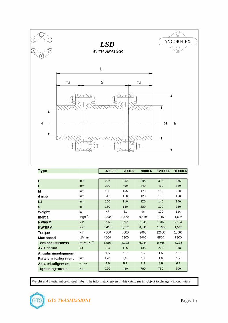
LSD
WITH SPACER
ANCORFLEX
L
L1 L1
d E M
S
Page: 15 GTS TRASMISSIONI
Type 4000-6 7000-6 9000-6 12000-6 15000-6
E mm 226 252 296 318 336
L mm 380 400 440 480 520
M mm 135 155 170 195 210
d max mm 95 110 120 138 150
L1 mm 100 110 120 140 150
S mm 180 180 200 200 220
Weight kg 47 61 96 132 166
Inertia (Kgm2) 0,235 0,458 0,819 1,267 1,896
HP/RPM N/n 0,568 0,995 1,28 1,707 2,134
KW/RPM N/n 0,418 0,732 0,941 1,255 1,569
Torque Nm 4000 7000 9000 12000 15000
Max speed (1/min) 8000 7500 6000 5500 5500
Torsional stiffness Nm/rad x106 3,996 5,192 6,024 6,748 7,293
Axial thrust Kg 104 115 138 279 358
Angular misalignment ° 1,5 1,5 1,5 1,5 1,5
Parallel misalignment mm 1,45 1,45 1,6 1,6 1,7
Axial misalignment ± mm 4,9 5,1 5,3 5,9 6,1
Tightening torque Nm 260 480 760 780 800
Weight and inertia unbored steel hubs The information given in this catalogue is subject to change without notice
LSD
WITH SPACER
ANCORFLEX
L
L1 L1
d E M
S

Page: 16 GTS TRASMISSIONI
Type 20000-8 25000-8 35000-8 50000-8 65000-8
E mm 322 352 386 426 456
L mm 312 344 387 417 452
M mm 190 218 252 272 292
d max mm 135 155 175 190 205
L1 mm 140 155 175 190 205
S mm 32 34 37 37 42
Weight kg 95 126 156 211 266
Inertia (Kgm2) 0,762 1,223 1,944 3,112 4,45
HP/RPM N/n 2,846 3,558 4,981 7,116 9,251
KW/RPM N/n 2,092 2,616 3,662 5,232 6,802
Torque Nm 20000 25000 35000 50000 65000
Max speed (1/min) 5500 5000 5000 4500 4000
Torsional stiffness Nm/rad x 106 22,325 37,763 51,582 64,341 69,893
Axial thrust Kg. 405 484 638 683 744
Angular misalignment ° 0,5 0,5 0,5 0,5 0,5
Tightening torque Nm 780 800 1100 1500 2600
Weight and inertia unbored steel hubs The information given in this catalogue is subject to change without notice
LS
WITHOUT SPACER
ANCORFLEX
L1 L1
d E M
S
L
Page: 17 GTS TRASMISSIONI
Weight and inertia unbored steel hubs The information given in this catalogue is subject to change without notice
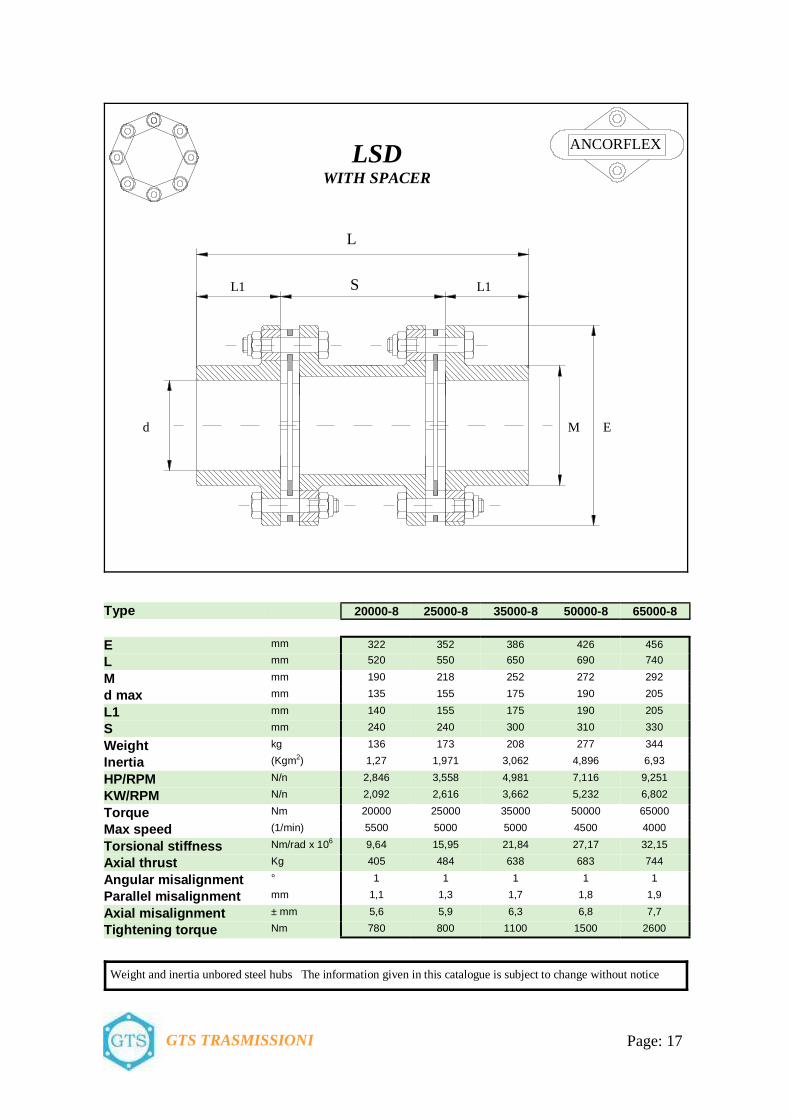
LSD
WITH SPACER
ANCORFLEX
L
L1 L1
d E M
S
Type 20000-8 25000-8 35000-8 50000-8 65000-8
E mm 322 352 386 426 456
L mm 520 550 650 690 740
M mm 190 218 252 272 292
d max mm 135 155 175 190 205
L1 mm 140 155 175 190 205
S mm 240 240 300 310 330
Weight kg 136 173 208 277 344
Inertia (Kgm2) 1,27 1,971 3,062 4,896 6,93
HP/RPM N/n 2,846 3,558 4,981 7,116 9,251
KW/RPM N/n 2,092 2,616 3,662 5,232 6,802
Torque Nm 20000 25000 35000 50000 65000
Max speed (1/min) 5500 5000 5000 4500 4000
Torsional stiffness Nm/rad x 106 9,64 15,95 21,84 27,17 32,15
Axial thrust Kg 405 484 638 683 744
Angular misalignment ° 1 1 1 1 1
Parallel misalignment mm 1,1 1,3 1,7 1,8 1,9
Axial misalignment ± mm 5,6 5,9 6,3 6,8 7,7
Tightening torque Nm 780 800 1100 1500 2600

Page: 18 GTS TRASMISSIONI
Weight and inertia unbored steel hubs The information given in this catalogue is subject to change without notice
LSDE
WITH SPACER
ANCORFLEX
L
L1 L1
d E M
S
M1 d1
Type 100-6 150-6 300-6 700-6 1100-6 1700-6 2600-6
E mm 80 92 112 136 162 182 206
L mm 110 116 136 168 202 225 239
M mm 45 53 64 77 92 112 128
M 1 mm 35 42 53 63 72 85 101
d max mm 32 38 45 55 65 80 90
d1 max mm 25 30 38 45 52 60 72
L1 mm 36 42 46 56 66 80 92
S mm 38 32 44 56 70 65 55
Weight kg 1,7 3,3 5,5 8,8 14,4 21 31
Inertia (Kgm2) 0,0009 0,0028 0,0073 0,0165 0,0171 0,064 0,13
HP/RPM N/n 0,014 0,021 0,043 0,099 0,156 0,241 0,37
KW/RPM N/n 0,011 0,016 0,031 0,073 0,115 0,177 0,272
Torque Nm 100 150 300 700 1100 1700 2600
Max speed (1/min) 25000 22000 20000 16000 14000 12000 10000
Torsional stiffness Nm/rad x 106 0,051 0,071 0,184 0,422 0,803 1,019 1,596
Axial thrust Kg 14 19 26 34 53 70 79
Angular misalignment ° 1,5 1,5 1,5 1,5 1,5 1,5 1,5
Parallel misalignment mm 0,32 0,42 0,53 0,74 0,84 0,92 0,96
Axial misalignment ± mm 1,6 1,9 2,5 2,9 3,3 4 4,5
Tightening torque Nm 12 13 22 39 85 95 127
Page: 19 GTS TRASMISSIONI
Weight and inertia unbored steel hubs The information given in this catalogue is subject to change without notice
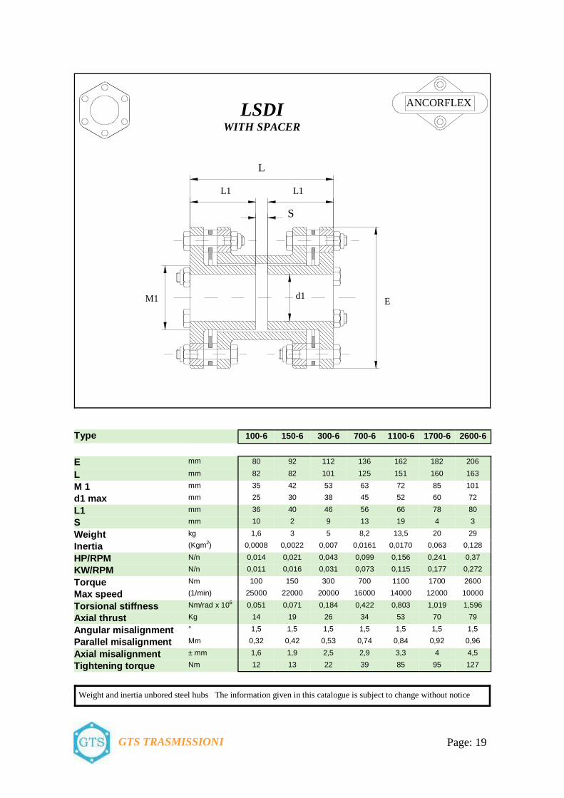
LSDI
WITH SPACER
ANCORFLEX
L
L1 L1
E
S
M1 d1
Type 100-6 150-6 300-6 700-6 1100-6 1700-6 2600-6
E mm 80 92 112 136 162 182 206
L mm 82 82 101 125 151 160 163
M 1 mm 35 42 53 63 72 85 101
d1 max mm 25 30 38 45 52 60 72
L1 mm 36 40 46 56 66 78 80
S mm 10 2 9 13 19 4 3
Weight kg 1,6 3 5 8,2 13,5 20 29
Inertia (Kgm2) 0,0008 0,0022 0,007 0,0161 0,0170 0,063 0,128
HP/RPM N/n 0,014 0,021 0,043 0,099 0,156 0,241 0,37
KW/RPM N/n 0,011 0,016 0,031 0,073 0,115 0,177 0,272
Torque Nm 100 150 300 700 1100 1700 2600
Max speed (1/min) 25000 22000 20000 16000 14000 12000 10000
Torsional stiffness Nm/rad x 106 0,051 0,071 0,184 0,422 0,803 1,019 1,596
Axial thrust Kg 14 19 26 34 53 70 79
Angular misalignment ° 1,5 1,5 1,5 1,5 1,5 1,5 1,5
Parallel misalignment Mm 0,32 0,42 0,53 0,74 0,84 0,92 0,96
Axial misalignment ± mm 1,6 1,9 2,5 2,9 3,3 4 4,5
Tightening torque Nm 12 13 22 39 85 95 127

Page: 20 GTS TRASMISSIONI
L1 L1
E
S
d1 M d d
Type LSA
E mm
L1 mm
M mm
d max mm
d1 max mm
S mm
Max speed 1/min
Torque Nm
100-6 80 35 50 35 48 28 25000 100
150-6 92 40 60 42 55 28 22000 150
300-6 112 45 77 55 75 34 20000 300
700-6 136 55 96 68 92 38 16000 700
1100-6 162 62 115 82 105 49 14000 1100
1700-6 182 70 134 95 120 50 12000 1700
2600-6 206 90 154 110 135 51 10000 2600
4000-6 226 115 165 118 150 62 8000 4000
7000-6 252 120 175 125 168 71 7500 7000
9000-6 296 130 198 140 198 80 6000 9000
12000-6 318 150 225 155 210 88 5500 12000
25000-8 352 170 255 180 230 90 5000 25000
35000-8 386 180 270 190 250 97 5000 35000
50000-8 426 190 290 205 280 97 4500 50000
65000-8 456 210 325 230 300 106 4000 65000
NSE e MONEL
LSA
WITHOUT SPACER
L1
3 8 MONEL
3 - Flexible elements 8 – Washers
MONEL MONEL
3 8 NSE
AISI 304-C Brass
3 - Flexible elements 8 – Washers

Page: 21 GTS TRASMISSIONI
NSE e MONEL
LSDA
WITH SPACER
L1 L1
E
S
d1 Md d
Type LDSA
E mm
L1 mm
M mm
d max mm
d1 max mm
S mm
Max speed 1/min
Coppia Nm
100-6 80 35 50 35 48 66 25000 100
150-6 92 40 60 42 55 66 22000 150
300-6 112 45 77 55 75 79 20000 300
700-6 136 55 96 68 92 99 16000 700
1100-6 162 62 115 82 105 121 14000 1100
1700-6 182 70 134 95 120 130 12000 1700
2600-6 206 90 154 110 135 131 10000 2600
4000-6 226 115 165 118 150 180 8000 4000
7000-6 252 120 175 125 168 180 7500 7000
9000-6 296 130 198 140 198 200 6000 9000
12000-6 318 150 225 155 210 200 5500 12000
25000-8 352 170 255 180 230 240 5000 25000
35000-8 386 180 270 190 250 300 5000 35000
50000-8 426 190 290 205 280 310 4500 50000
65000-8 456 210 325 230 300 330 4000 65000
L1
N 3 8 5
3 - Flexible elements 5 - Ring 8 – Washers
AISI 304-C Bronze Brass
MONEL 3 8 5
3 - Flexible elements 5 - Ring 8 – Washers
Monel Bronze Monel

Page: 22 GTS TRASMISSIONI
N SDA SA H
LSDA-H LSA-H
LSDA-N LSA-N
LSDA LSA
Combination examples

Page: 23 GTS TRASMISSIONI
d1
L1
M Ed
LL1 S L1
NE
I
M
LSD “ACE”
Executions: LSD-ACE IE = 1 internal hub + 1 external hub LSD-ACE IN = 1 internal hub + 1 standard hub LSD-ACE II = 2 internals hubs LSD-ACE EN = 1 external hub + 1 standard hub LSD-ACE EE = 2 externals hubs
Type 1100-6 1700-6 2600-6
E mm 156 176 196
L mm 182 206 228
M mm 95 110 134
d mm 50 60 80
d1 max mm 68 78 94
L1 mm 56 68 74
S mm 70 70 80
Weight kg 9 14 22
Inertia (Kgm2) 0,0170 0,060 0,120
HP/RPM N/n 0,156 0,241 0,37
KW/RPM N/n 0,115 0,177 0,272
Torque Nm 1100 1700 2600
Max speed (1/min) 14000 12000 10000
Torsional stiffness Nm/rad x 106 0,803 1,019 1,596
Axial thrust Kg 53 70 79
Angular misalignment ° 1,5 1,5 1,5
Parallel misalignment mm 0,67 0,71 0,73
Axial misalignment ± mm 3,3 4 4,5
Tightening torque Nm 85 95 127
The keyless shaft hub connection “ACE” eliminates the play between the shaft and the hub and distributes the power transmissions over the entire surface while with a key con-nection the transmission is concentrated on a limited area only. Simple mounting and dis-mounting allows easy and quick changing of the hubs fitted on the shaft; the high pressure between the contact surfaces avoid rust and, years after installation , allows a quick re-moval of the hub.

Special executions
For retention and repeatability of balance in high speed couplings to adopt that illustrated: the adaptor and spacer are accurately located through the flexible element, so en-suring concentricity whilst allowing full flexibility.
Execution for high speed HSE Range
On application involving electric motor driven pumps, it is often nec-essary to insulate against eddy cur-rents. Such insulation can readily be introduced between adaptor and hub as illustrated.
EIE Range
For ease of fitting hubs to shafts it is possible to include taper bushes or the ringfedder system of attachment.
RFE Range
With shear pins
PRE Range
When fitting direct to customer’s existing shaft flangest will often be found that the attachment hole arrangement, or the di-ameter of flange, will not conveniently fit with conventional adaptor plate. In such cases special adapters are used as illus-trated.
CFE Range
In some instances, due to a very small shaft separation, it is not practicable to fit a con-ventional type of spacer. In these cases it is often possible to make the spacer portion in the form of single plate.
SRE Range
With reversed hubs and spacer in to half
GCE Range
For vertical applications, particu-larly when using long or heavy units, it is necessary to support the weight of the spacer to prevent damage to the flexible elements. This can be done by the simple method illustrated where the thrust bearing of the lower machine takes the weight.
BME Range
GTS TRASMISSIONI Page: 2

ASSEMBLY The user is responsible for the provision of safety guards and correct installation of all equipment It is important that initial alignment should be as close as practicable, both axially and radially, to allow for changes in condition during operation and ensure a long working life.
Parallel bored hubs should be fitted so that the shaft end is flush with the flange face. The “S” dimension will them be the same as the distance between shaft ends. Hubs bored for interference fit should be heated in oil at 120° - 140° C, and quickly positioned on the shaft. Do not spot heat as it may cause local distortion. Couplings whit adaptors, LSDA, are fitted to the hubs by means of spigoto register. To assemble or dismantle the central “S” portion requires it to be compressed by an amount of at least twice the spigot depth. This can be achieved by the use of special compression caps or cradle. In the case of smaller units compression of the centre section is possible by inserting a screw driver between adaptor and hub flange taking care not to damage the mating surfaces. The “S” is therefore a pre-assembled set: so is very simple and fast to take out if for routine maintenance to the machines, without removing the alignment.
An initial and rough radial alignment can be made by laying a straight edge across the flanges of the two hubs. Remember to check in the vertical as well as the horizontal plane.
s
GTS TRASMISSIONI Page: 2

Having brought the two ends into a roughly correct position the centre section of the coupling can now be assembled and final alignment achieved as follows to check the angular and radial misalignment simultaneously: 1 – Attach a dial indicator to one flange and,
Assembled the coupling, establish the minimum reading. 2 – To accurately measure either over the flange or the element gap, applying minimum pressure, to obtain
the high point S2 and the low point S1:
Divide the difference between point S“ and S1 by the coupling flange diameter “E“. This procedure will give an answer in mm/mm which should not be larger than the figure given below: 4 bolt coupling 0,004 mm/mm of flange diameter “E” 6 bolt coupling 0,003 mm/mm of flange diameter “E” 8 bolt coupling 0,002 mm/mm of flange diameter “E”
S2
S1
E
GTS TRASMISSIONI Page: 2

Flexible all metal Couplings for IEC standard motors 50 Hz n= 1000 (1/min ) Power ratings of IEC motors and associated LS - LSD -LSA- LSDA couplings 50 Hz n=750 (1/min )
Service Factors arrangement 1,5 2 2,5 3 3,5 Power Ratings Coupling Power Ratings Coupling to 50 Hz to 50 Hz n= 1000 n= 750 (1/min) Service Factors (1/min) Service Factors
This arrangement offers safety for average loadings with up to 5 starts per hour. For driven ma-chines with very heavy shock loads it is advisable to recalculate with the service factor (Page 4).
motor KW Nm 1,5 2 2,5 3 3,5 KW Nm 1,5 2 2,5 3 3,5
80 0,37 3,9 100-6 100-6 100-6 100-6 100-6 0,18 2,6 100-6 100-6 100-6 100-6 100-6
0,55 5,8 100-6 100-6 100-6 100-6 100-6 0,25 3,6 100-6 100-6 100-6 100-6 100-6
90 S 0,75 8,0 100-6 100-6 100-6 100-6 100-6 0,37 5,3 100-6 100-6 100-6 100-6 100-6
90 L 1,1 12 100-6 100-6 100-6 100-6 100-6 0,55 7,9 100-6 100-6 100-6 100-6 100-6
100 L 1,5 15 100-6 100-6 100-6 100-6 100-6 0,75 11 100-6 100-6 100-6 100-6 100-6
1,1 16 100-6 100-6 100-6 100-6 100-6
112 M 2,2 22 100-6 100-6 100-6 100-6 100-6 1,5 21 100-6 100-6 100-6 100-6 100-6
132 S 3 30 100-6 100-6 100-6 100-6 100-6 2,2 29 100-6 100-6 100-6 100-6 100-6
132 M 4 40 100-6 100-6 100-6 150-6 150-6 3 40 100-6 100-6 100-6 150-6 150-6
5,5 55 100-6 150-6 150-6 300-6 300-6
160 M 7,5 74 150-6 150-6 300-6 300-6 300-6 4 54 100-6 150-6 150-6 300-6 300-6
5,5 74 150-6 150-6 300-6 300-6 300-6
160 L 11 108 300-6 300-6 300-6 700-6 700-6 7,5 100 150-6 300-6 300-6 300-6 700-6
180 L 15 147 300-6 300-6 700-6 700-6 700-6 11 147 300-6 300-6 700-6 700-6 700-6
200 L 18,5 186 300-6 700-6 700-6 700-6 700-6 15 196 300-6 700-6 700-6 700-6 700-6
22 216 700-6 700-6 700-6 700-6 1100-6
225 S 18,5 245 700-6 700-6 700-6 1100-6 1100-6
225 M 30 294 700-6 700-6 1100-6 1100-6 1100-6 22 294 700-6 700-6 1100-6 1100-6 1100-6
250 M 37 363 700-6 1100-6 1100-6 1100-6 1700-6 30 392 700-6 1100-6 1100-6 1700-6 1700-6
280 S 45 441 700-6 1100-6 1100-6 1700-6 1700-6 37 490 1100-6 1100-6 1700-6 1700-6 1700-6
280 M 55 539 1100-6 1100-6 1700-6 1700-6 2600-6 45 588 1100-6 1700-6 1700-6 2600-6 2600-6
315 S 75 725 1100-6 1700-6 2600-6 2600-6 2600-6 55 715 1100-6 1700-6 2600-6 2600-6 2600-6
315 M 90 872 1700-6 1700-6 2600-6 2600-6 4000-6 75 970 1700-6 2600-6 2600-6 4000-6 4000-6
110 1080 1700-6 2600-6 4000-6 4000-6 4000-6 90 1180 1700-6 2600-6 4000-6 4000-6 4000-6
132 1290 2600-6 2600-6 4000-6 4000-6 7000-6 105 1360 2600-6 4000-6 4000-6 4000-6 7000-6
355 S 160 1570 2600-6 4000-6 4000-6 7000-6 7000-6 145 1870 4000-6 4000-6 7000-6 7000-6 7000-6
355 M 190 1840 4000-6 4000-6 7000-6 7000-6 7000-6 165 2130 4000-6 7000-6 7000-6 7000-6 7000-6
GTS TRASMISSIONI Page: 2
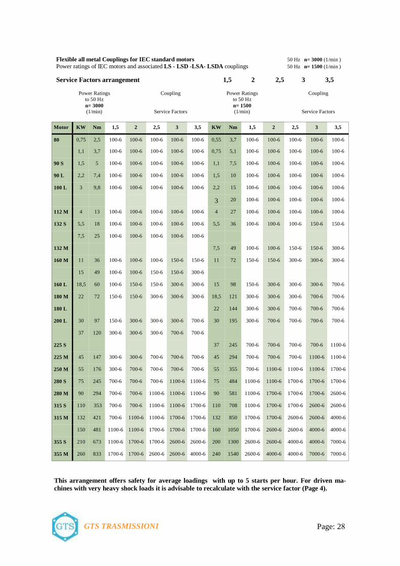
Flexible all metal Couplings for IEC standard motors 50 Hz n= 3000 (1/min ) Power ratings of IEC motors and associated LS - LSD -LSA- LSDA couplings 50 Hz n= 1500 (1/min )
Service Factors arrangement 1,5 2 2,5 3 3,5 Power Ratings Coupling Power Ratings Coupling to 50 Hz to 50 Hz n= 3000 n= 1500 (1/min) Service Factors (1/min) Service Factors
Motor KW Nm 1,5 2 2,5 3 3,5 KW Nm 1,5 2 2,5 3 3,5
80 0,75 2,5 100-6 100-6 100-6 100-6 100-6 0,55 3,7 100-6 100-6 100-6 100-6 100-6
1,1 3,7 100-6 100-6 100-6 100-6 100-6 0,75 5,1 100-6 100-6 100-6 100-6 100-6
90 S 1,5 5 100-6 100-6 100-6 100-6 100-6 1,1 7,5 100-6 100-6 100-6 100-6 100-6
90 L 2,2 7,4 100-6 100-6 100-6 100-6 100-6 1,5 10 100-6 100-6 100-6 100-6 100-6
100 L 3 9,8 100-6 100-6 100-6 100-6 100-6 2,2 15 100-6 100-6 100-6 100-6 100-6
3 20 100-6 100-6 100-6 100-6 100-6
112 M 4 13 100-6 100-6 100-6 100-6 100-6 4 27 100-6 100-6 100-6 100-6 100-6
132 S 5,5 18 100-6 100-6 100-6 100-6 100-6 5,5 36 100-6 100-6 100-6 150-6 150-6
7,5 25 100-6 100-6 100-6 100-6 100-6
132 M 7,5 49 100-6 100-6 150-6 150-6 300-6
160 M 11 36 100-6 100-6 100-6 150-6 150-6 11 72 150-6 150-6 300-6 300-6 300-6
15 49 100-6 100-6 150-6 150-6 300-6
160 L 18,5 60 100-6 150-6 150-6 300-6 300-6 15 98 150-6 300-6 300-6 300-6 700-6
180 M 22 72 150-6 150-6 300-6 300-6 300-6 18,5 121 300-6 300-6 300-6 700-6 700-6
180 L 22 144 300-6 300-6 700-6 700-6 700-6
200 L 30 97 150-6 300-6 300-6 300-6 700-6 30 195 300-6 700-6 700-6 700-6 700-6
37 120 300-6 300-6 300-6 700-6 700-6
225 S 37 245 700-6 700-6 700-6 700-6 1100-6
225 M 45 147 300-6 300-6 700-6 700-6 700-6 45 294 700-6 700-6 700-6 1100-6 1100-6
250 M 55 176 300-6 700-6 700-6 700-6 700-6 55 355 700-6 1100-6 1100-6 1100-6 1700-6
280 S 75 245 700-6 700-6 700-6 1100-6 1100-6 75 484 1100-6 1100-6 1700-6 1700-6 1700-6
280 M 90 294 700-6 700-6 1100-6 1100-6 1100-6 90 581 1100-6 1700-6 1700-6 1700-6 2600-6
315 S 110 353 700-6 700-6 1100-6 1100-6 1700-6 110 708 1100-6 1700-6 1700-6 2600-6 2600-6
315 M 132 421 700-6 1100-6 1100-6 1700-6 1700-6 132 850 1700-6 1700-6 2600-6 2600-6 4000-6
150 481 1100-6 1100-6 1700-6 1700-6 1700-6 160 1050 1700-6 2600-6 2600-6 4000-6 4000-6
355 S 210 673 1100-6 1700-6 1700-6 2600-6 2600-6 200 1300 2600-6 2600-6 4000-6 4000-6 7000-6
355 M 260 833 1700-6 1700-6 2600-6 2600-6 4000-6 240 1540 2600-6 4000-6 4000-6 7000-6 7000-6
This arrangement offers safety for average loadings with up to 5 starts per hour. For driven ma-chines with very heavy shock loads it is advisable to recalculate with the service factor (Page 4).
GTS TRASMISSIONI Page: 2

Page: 30 GTS TRASMISSIONI
Page 2-3 –Characteristics
4 Coupling selection
5 Service factors
6 General information – Particular information
7 LSDA with spacer and adaptors 6 bolts, continuus ring
8 LSDA N with spacer and adaptors 6 bolts, continuus ring
9 LSDA H with spacer and adaptors 6 bolts, continuus ring
10 LSDA with spacer and adaptors 6 bolts, separate link
11 LSDA with spacer and adaptors 8 bolts, separate link
12 LS without spacer 6 bolts, continuus ring
13 LS without spacer 6 bolts, separate link
14 LSD with spacer 6 bolts, continuus ring
15 LSD with spacer 6 bolts, separate link
16 LS without spacer 8 bolts, separate link
17 LSD with spacer 8 bolts, separate link
18 LSDE with spacer 6 bolts, continuus ring
19 LSDI with spacer 6 bolts, continuus ring
20 LSA without spacer NSE and MONEL
21 LSDA with spacer NSE and MONEL
22 Combination examples
23 LSD “ACE” range with shrink disc
Special execution
GTS
Contents
2 Assembly
2 Assembly
2 Couplings for IEC standard motors
2 Couplings for IEC standard motors

Page: 32 GTS TRASMISSIONI

GTS TRASMISSIONI
E-mail: [email protected] Sito Web: http//www.gtstrasmissioni.com
Via Montello, 33 – 20093 Cologno Monzese (Milano) Telefoni 02.26.70.81.71 – 02.26.70.82.46 – 02.26.70.89.50 Fax 02.26.70.89.43