casl product applications 03192013 applications (vera) that can be employed by users to analyze...
TRANSCRIPT


Page i 3/20/2013
Oak Ridge National Laboratory in partnership with Electric Power Research Institute Idaho National Laboratory Los Alamos National Laboratory Massachusetts Institute of Technology North Carolina State University Sandia National Laboratories Tennessee Valley Authority University of Michigan Westinghouse Electric Company and individual contributions from Anatech Corporation Pacific Northwest National Laboratory ASCOMP GmbH Pennsylvania State University CD‐adapco, Inc Rensselaer Polytechnic Institute Core Physics, Inc. Southern States Energy Board City University of New York Texas A&M University Florida State University University of Florida Notre Dame University University of Tennessee Imperial College London University of Wisconsin

Page ii 3/20/2013
REVISION LOG
Revision Date Affected Pages Revision Description
0.0 02/28/13 All Initial draft
1.0 03/20/13
See tracked changes as indicated by lines in the right margin. Note that some minor formatting changes are not tracked.
Revised document as needed to reflect CASL staff and independent reviewer comments and feedback. Added information and reference for Peregrine.

Page iii 3/20/2013
CONTENTS CONTENTS ................................................................................................................................... iii List of Tables and Figures.............................................................................................................. iv ACRONYMS .................................................................................................................................. v 1 Introduction ............................................................................................................................. 1 2 Objectives and Scope .............................................................................................................. 1 3 CASL Foundational Products ................................................................................................. 1
3.1 CASL Solutions Technology ........................................................................................... 2 3.2 CASL Modeling & Simulation Technology .................................................................... 3 3.3 The Physics Studied within the CASL Technologies ...................................................... 4 3.4 CASL’s Coupled Foundational Physics Package, VERA ................................................ 6
3.4.1 VERA, Leadership-class Platform ............................................................................ 8 3.4.2 VERA, Industry-class Platform .............................................................................. 11 3.4.3 The VERA Infrastructure and User Application Coupling ..................................... 13
4 The Industry Challenge Problem Approach: Applied VERA Physics Combinations and Supporting Tools ........................................................................................................................... 14
4.1 CASL’s Coolant Chemistry ModSim Technology ........................................................ 14 4.1.1 CASL Coolant Chemistry ModSim Methods ......................................................... 16 4.1.2 CASL Coolant Chemistry Coupled Physics and Recommended ModSim Approach 17
4.2 CASL’s Grid-to-Rod Fretting ModSim Technology ..................................................... 18 4.2.1 CASL GTRF ModSim Methods ............................................................................. 20 4.2.2 CASL GTRF Coupled Physics and Recommended ModSim Approach ................ 21
4.3 CASL’s Pellet-Cladding Interaction (PCI) ModSim Technology ................................. 22 4.3.1 CASL PCI ModSim Methods ................................................................................. 23 4.3.2 CASL PCI Coupled Physics and Recommended ModSim Approach .................... 25
5 CASL Baseline Tools ........................................................................................................... 26 6 CASL Solutions Database .................................................................................................... 27 7 Technology Delivery ............................................................................................................ 33
7.1 CASL ModSim Product Distributions ........................................................................... 33 7.2 Test Stands ..................................................................................................................... 33 7.3 Pilot Projects .................................................................................................................. 33 7.4 Education and Training .................................................................................................. 33
8 CASL’s Future Products ....................................................................................................... 35 9 References ............................................................................................................................. 38

Page iv 3/20/2013
List of Tables and Figures Table 1 General Needs for Simulation of Commercial PWRs ...................................................... 5
Table 2 Comparison of VERA with Typical Industry Core Simulator Methods [Ref. 3, modified]......................................................................................................................................................... 7
Table 3 CASL Solutions Technology Product Listing ................................................................. 27
Table 4 Evolution of CASL’s ModSim Technology ................................................................... 36
Figure 1 CASL ModSim Technology (VERA) Layered, Integrated Multi-Physics Developmental Approach ......................................................................................................................................... 4
Figure 2 VERA Foundational Toolset Coupled Interfaces .......................................................... 12
Figure 3 Challenge Problems Drive CASL Software and Solutions Development ..................... 14
Figure 4 SEM Image of PWR CRUD Flake (courtesy EPRI) ..................................................... 15
Figure 5 Physics Feedback for CIPS ModSim ............................................................................ 17
Figure 6 Typical GTRF Wear Scar [courtesy Westinghouse Electric Corp.] .............................. 18
Figure 7 PWR Fuel Leaker Mechanisms (U.S.) and Number of Assemblies Discharged per year due to GTRF through 2012 [Data source: EPRI FRED Database] ............................................... 18
Figure 8 Examples of Specific Fuel Design Influences on GTRF-related Assembly Discharges through 2012 [Data source: EPRI FRED Database] ..................................................................... 19
Figure 9 Physics Feedback for GTRF ModSim ............................................................................ 21
Figure 10 Number of Assemblies Discharged per year due to Duty-related Failures in the U.S. through 2012 [Data source: EPRI FRED Database] ..................................................................... 22
Figure 11 Physics Feedback for PCI ModSim .............................................................................. 25

Page v 3/20/2013
ACRONYMS AMA Advanced Modeling Applications BWR boiling water reactor CASL Consortium for Advanced Simulation of Light Water Reactors CILC CRUD‐induced localized corrosion CIPS CRUD‐induced power shift CFD computational fluid dynamics CRUD corrosion‐related unidentified deposits or Chalk River unidentified deposits DNB departure from nucleate boiling DOE U.S. Department of Energy DOE‐NE U.S. Department of Energy Office of Nuclear Energy EIH Energy Innovation Hub EPRI Electric Power Research Institute FA Focus Area GTRF grid‐to‐rod‐fretting HPC high‐performance computing IC Industry Council INL Idaho National Laboratory LANL Los Alamos National Laboratory LOCA loss of coolant accident LWR light water reactor M&S modeling and simulation MIT Massachusetts Institute of Technology MPO Materials Performance and Optimization NCSU North Carolina State University NRC Nuclear Regulatory Commission NSSS nuclear steam supply system ORNL Oak Ridge National Laboratory PCI pellet‐cladding interaction PWR pressurized water reactor R&D research and development RIA reactivity insertion accident RSICC Radiation Safety Information Computational Center RTM Radiation Transport Methods SMR small modular reactor SNL Sandia National Laboratories T‐H thermal‐hydraulics THM Thermal Hydraulics Methods TVA Tennessee Valley Authority UM University of Michigan V&V verification and validation VERA Virtual Environment for Reactor Applications VERA‐CS VERA‐Core Simulator VERA‐IC VERA scaled for industry‐class platforms VERA‐LP VERA scaled for leadership‐class platforms VOCC Virtual Office, Community, and Computing VRI Virtual Reactor Integration VUQ Validation and Uncertainty Quantification WEC Westinghouse Electric Company

Page 1 of 39 3/20/2013
1 Introduction Commercial nuclear power reactors are easily described: fuel pellets are stacked in thin rods that are maintained in place through a metallic mechanical structure called a fuel assembly; many fuel assemblies are packed together into a pressure vessel; water is pumped through the fuel assemblies to cool them and to collect heat that is transferred to a turbine to make electricity.
Although it is easily described and each of the various aspects of the operation - the fuel pellets producing neutrons, the heating of the metal and water, and the flow of the coolant through the reactor - are routinely simulated individually, we haven’t, until recently, had the computing power to simulate all of the physical phenomenon driving the commercial pressurized water reactor simultaneously.
At most utilities and fuel vendors, the phenomena are broken into the individual physics and are analyzed independently from each other based on simplifications and applied boundary conditions. For example, a nuclear engineer calculates rod power distributions using simplified thermal/hydraulic models to determine the coolant flow, temperature, and density distributions, while the thermal-hydraulics engineer in the next cubicle calculates more detailed coolant flow, temperature, and density distributions based on conservative assumptions for rod power distributions that conservatively bound those calculated by the nuclear engineer. Clearly these phenomena are directly related and a more accurate depiction of the power, coolant temperature and density would be obtained if the calculations were completed in a coupled manner.
The Consortium for Advanced Simulation of Light Water Reactors (CASL) is the first DOE Energy Innovation Hub, established in July 2010 for the modeling and simulation (ModSim) of commercial nuclear power reactors. CASL’s mission, as established in Ref. 1, is to provide usable coupled, higher-fidelity modeling and simulation capabilities to address light water reactor operational and safety performance-defining phenomena and to transfer the technology to the U.S. nuclear community.1
2 Objectives and Scope This document provides a description of CASL’s current technology products, presents the envisioned technology transfer methods, and discusses the future evolution of CASL technology products. For purposes of defining the product and technology transfer methods, CASL’s intended user group is broadly defined as the U.S. nuclear community; as this work is expanded the broad user group will be partitioned into more specific subgroups.
3 CASL Foundational Products CASL’s technology represents a step change in the simulation of commercial nuclear power plants and provides new insights on their operation, performance and safety. As mentioned previously, the traditional reactor design and analysis process relies on tools that are not fully integrated and coupled, with the analyses progressing through sequential simulation of different areas of physics, such as radiation transport (neutronics), fluid flow (thermal-hydraulics or T-H), 1 The U.S. nuclear community includes the stakeholders defined by Reference 1: U.S. DOE Office of Nuclear Energy (NE) and the CASL Consortium, U.S. Nuclear Regulatory Commission (NRC), nuclear R&D community (including US Laboratories and Universities), and the nuclear industry.

Page 2 of 39 3/20/2013
and fuel thermo-mechanics. Structural analyses and coolant chemistry-fuel interaction simulations are usually performed on an as-needed basis. Since the industry ModSim tools are not fully coupled, multiple conservative assumptions must be made to ensure a conservative simulation, likely resulting in increased energy cost. Additionally, if downstream analyses indicate the necessity of design modifications, the simulation must be repeated from the beginning. CASL’s approach allows a more integrated design cycle that can more adequately account for interactions between relevant physical phenomena. The integrated, coupled solutions are expected to reduce the uncertainties intrinsic in sequential analyses and provide a more realistic representation of the reactor behavior. Even more importantly, it will provide a more rigorous representation of the plant behavior for simulation of accident conditions.
Towards achieving the CASL mission, several CASL technologies are under development and are broadly classified under two categories: Solutions and Modeling & Simulation (ModSim).
• CASL’s Solutions Technology is defined by the combined knowledge, and expertise of the CASL team, including knowledge about how to simulate nuclear energy processes (fundamental insights, modeling techniques, computer science solutions, etc.) that have been developed and published under CASL.
• CASL’s ModSim Technology provides a coupled high-fidelity Virtual Environment for Reactor Applications (VERA) that can be employed by users to analyze nuclear energy problems.
Thus, CASL has contributed to the nuclear community’s state of knowledge and contributed tools that can be used to further extend that state of knowledge.
3.1 CASL Solutions Technology The CASL staff has a unique team experience and comprehensive nuclear and application development knowledge-base, and this knowledge and experience is being leveraged in conjunction with the National Lab's world-class computing capability to produce solutions for the toughest industry issues. CASL Solutions Technology includes:
o Developmental expertise for creation of modeling & simulation tools having higher-fidelity predictive capability in the field of commercial nuclear power generation;
o Benchmark simulations with comparisons against operational data from commercial reactors to demonstrate application performance and to facilitate potential User licensure;2
o Published results of Challenge Problem3 simulations and other related simulations completed by CASL staff using VERA (“Pilots”);
o Simulation methods established through Benchmark simulations and Pilot simulations,
o Position statements and guidance based on CASL technology;
2 Note that this category of information bridges between both Solutions and ModSim Technologies, as the simulations support the team’s knowledge-base while also providing necessary confidence in the ModSim tools necessary to support use and licensure of the technology. 3 See Section 4 for a description of CASL’s Challenge Problems.

Page 3 of 39 3/20/2013
o Engagement of the Nuclear Energy Community through Modeling and Simulation.
3.2 CASL Modeling & Simulation Technology An integrated and coupled suite of robust, validated, and usable simulation tools within a common, multi-physics virtual environment for reactor applications (VERA) that can produce higher-fidelity predictive capability for component performance through the onset of failure and effectively apply it to enhance nuclear safety and efficiency, including:
o Scalable, robust, modern applications for 3D, full-core thermal hydraulics;
o Scalable, robust, modern applications for 3D, full-core pin-resolved radiation transport;
o Scalable, robust, modern applications for 3D, full-core pin-resolved fuel performance;
o Physics-based materials models of the fuel system and reactor vessel and internals, utilizing improved constitutive models of coolant and corrosion chemistry;
o Integrated uncertainty quantification tools for VERA verification and validation, calibration through data assimilation, sensitivity analysis, discretization error analysis and control, uncertainty quantification, and predictive maturity assessment;
o A Core Simulator functional tool set (VERA-CS) that provides: core depletion, pin powers, peaking factors and margins; control rod movement, detectors and boron search; and fuel shuffles from cycle to cycle.
o The coupled physics capabilities that address ModSim of the Challenge problems;
o The VERA simulation framework that allows other subcomponent physics applications to be utilized in a coupled manner with or without CASL subcomponent physics applications;
o Models and mesh established through Benchmark simulations and Pilot simulations;
o Benchmark simulations with comparisons against operational data from commercial reactors to demonstrate application performance and to facilitate potential User licensure.2
It should be noted that VERA includes both high performance computing (HPC) platform solutions and lesser platform solutions to provide useful and sustainable VERA products across the VERA user group. CASL’s intended user group (the U.S. nuclear community1) reflects a broad and diverse set of computational capabilities and ModSim needs, and the establishment of both HPC and lesser platform solutions provides capabilities for the majority of the CASL user group.
The CASL VERA is released periodically to the user group (a “public” release4) and is released more frequently to the CASL development team (“snapshot” release, see Ref. 2 for an example). The public release is considered to be CASL’s formal Modeling & Simulation Technology product release. Additionally, snapshots may be provided to institutions for alpha testing activities (“Test Stands”). While Test Stands are not considered to be CASL Technology ModSim Products, the simulations, meshes & models, publications and knowledge gained
4 As limited by export control, etc. . . . .

Page 4 of 39 3/20/2013
through the Test Stand application are considered to be CASL Technology Solutions and ModSim products.
3.3 The Physics Studied within the CASL Technologies Given CASL’s objectives, there is an emphasis on particular physics capabilities and coupling of the physics capabilities. Table 1 provides a summary of the general needs for simulation of commercial PWRs, and illustrates the intimate, mutually dependent relationships among the physical phenomenon. Figure 1 illustrates CASL’s layered, integrated multi-physics approach: a multi-physics integrator at the hub of a foundational set of applications (VERA) with specialized tool sets interfaced as needed to address specific Challenge Problem requirements. Pervasive uncertainty quantification ensures an understanding of the extents of the simulations, and a utilities tool set provides the necessary user interfaces (note that meshing is not within the current CASL development scope but is recognized as a necessary utility). The conditions of the simulation, representing the initial and boundary conditions of the simulations, are derived from the Normal Conditions of operation (current CASL scope) and Hypothetical Accident Conditions of operation (potential future CASL scope).
The selective advancement of the underlying phenomological models and the numerical implementations of those models, the judicious coupling of the physics, and the integrated uncertainty quantification provide the unique capability and higher-fidelity simulations needed to enhance efficiency and power production at the existing nuclear power fleet. In order to ensure that CASL Technologies include the necessary physics capability advancements within the VERA, the CASL project has adopted a “Challenge Problem” approach to focus and motivate specific development and enable R&D. Section 4 therefore discusses the CASL Technologies with respect to the solution of the selected Challenge Problems and the related VERA Tool Sets.
Figure 1 CASL ModSim Technology (VERA) Layered, Integrated Multi-Physics Developmental Approach

Page 5 of 39 3/20/2013
Table 1 General Needs for Simulation of Commercial PWRs
Foundational Physics Needs Specific Challenge Problem Tool Set Needs
Feedback Effects
Neu
tron
Tr
ansp
ort
• Local neutron flux; • Local Rod power; • Fission and depletion cross-sections;
• Depletion tracking; • Ability to model grids discretely; • Azimuthal cladding and pellet
temperatures; • Capability to calculate reactor
and fuel structure doses; • Local Boron concentration;
• Local coolant temperature & density;
• Local Fuel temperature • Rod bow performance; • Assembly bow performance • CRUD deposition feedback;
Ther
mal
-Hyd
raul
ics • Local axial and cross flow;
• Local coolant temperature and density;
• Coolant pressure drop; • Coolant mixing/turbulence; • Bypass mass flow
Local rod surface temperature; • Net hydraulic loads; • Heat transfer coefficients; • Flow friction/continuity descriptors.
• Analytical DNB predictions and DNBR/margin;
• Fluid-structure interaction excitation loads;
• Ability to accurately calculate pressure drop across components
• Local fuel temperature; • CRUD deposition feedback;
Fuel
Rod
Per
form
ance
• Local fuel temperature; • Pellet densification and swelling; • Fission gas release; • Pellet crack/relocation & rim size; • Pellet thermal conductivity; • Clad oxidation, hydrogen pickup and
hydriding; • Clad thermal and irradiation creep; • Fuel rod internal pressure; • Cladding stress/strain; • Pellet/clad interaction status and
local stress/strain, pellet relocation effects;
• Maneuvering performance
• Coupled ability to analyze missing pellet surfaces and prediction of localized clad stress and strain;
• Assembly distortion performance;
• Component and assembly vibration frequency & amplitude and wear depths, including grid-to-rod fretting wear;
• Clad plasticity models; • Rod bow model; • Irradiation growth and creep;
• Local Rod Power; • Local coolant heat transfer
coefficients; • CRUD deposition feedback; • GTRF wear feedback;
Cha
lleng
e Pr
oble
m S
peci
fic • Coolant chemistry and CRUD
deposition models; • Fluid-structure interaction
models; • Clad-grid support gaps; • Reactor CRUD inventory. • Assembly distortion model; • Structure/rod Oxidation and
hydriding • Structure/Joint/nozzle stress &
strain
• Local boron concentration & depletion;
• structure and rod irradiation growth;
• Rod waterside diameter;

Page 6 of 39 3/20/2013
3.4 CASL’s Coupled Foundational Physics Package, VERA The foundation of CASL’s coupled capabilities lies with the physics encompassed within VERA. CASL’s commitment to higher fidelity understanding of reactor phenomenon requires a more rigorous approach to radiation transport, fluid flow and fuel rod performance prediction, and this has spurred investments in 3D discrete ordinates (Sn) radiation transport methods; hybrid finite-volume/finite-element incompressible/low-Mach flow solvers; and 3D finite element solid mechanics utilizing enhanced material modeling techniques. This highest-fidelity CASL capability is termed, “VERA, Leadership-class Platform” or “VERA-LP.”
Recognizing the need for higher-fidelity simulations on an industry-sized computing platform, CASL has elected to provide additional capabilities using alternative, less computationally intensive methods such as 2D/1D Methods-of-Characteristics (MOC) radiation transport; sub-channel flow solutions; and 2D (r,z) finite element fuel rod mechanics utilizing enhanced material modeling techniques. The faster running higher-fidelity foundational capability is termed, “VERA, Industry-class Platform” or “VERA-IC.” It should be noted that even the Industry-class platform represents an impressive computing cluster at 1,000 cores and higher.
Table 2 provides a comparison between typical industry core simulators and CASL’s VERA approach to provide a higher-fidelity, coupled simulation capability for existing LWRs. Note that the current CASL ModSim and solutions technologies are focused on quasi-steady state normal operating conditions.
The following sections describe the VERA foundational applications and the VERA coupled physics interfaces.

Page 7 of 39 3/20/2013
Table 2 Comparison of VERA with Typical Industry Core Simulator Methods [Ref. 3, modified]
Physics Area Typical Industry Core Simulator Method VERA-IC VERA-LP
Neutron Transport
3-D diffusion (core)
2 energy groups (core)
2-D transport on single assemblies
2D/1D transport
23+ energy groups
3D transport
23+ energy groups
Thermal-Hydraulics nodal average (1-D) subchannel
(w/crossflow) subchannel
(w/crossflow) or CFD
Fuel Performance Bounding empirically-based pin-by-pin (r,z) pin-by-pin
Fuel & clad Temperatures nodal average & peak pin-by-pin (r,z) pin-by-pin
Power Distribution
nodal average with pin-power reconstruction explicit pin-by-pin explicit pin-by-pin
Xenon/Samarium nodal average w/correction pin-by-pin pin-by-pin
Depletion
infinite-medium cross sections,
quadratic burnup correction
history corrections, spectral corrections, reconstructed pin
exposures
pin-by-pin with actual core conditions
pin-by-pin with actual core conditions
Reflector Models 1-D cross section models actual 3D geometry actual 3D geometry
Target Platforms5
workstation (six-core) 1,000 cores and up 10,000 – 300,000 cores
~110 Gflops6 ~18 Tflops ~180 Tflops - 20 Pflops
~16 GB ~3 TB ~30 TB - 700 TB
5 ORNL Titan performance is more than 20 Pflops, sustaining more than 20,000 trillion calculations per second. the Titan cluster has almost 300 thousand cores and 710 TB of RAM. So, how much faster would this be than a typical workstation PC? First it should be said that operating speed is highly dependent upon the particular processor. However, as an example, in 2010 the fastest six-core PC processor reached 109 gigaFLOPS (Intel Core i7 980 XE)[16]in double precision calculations. Therefore, the Titan is about 18,350 times faster than a workstation with this processor. If you had a 1000-core cluster with this processor, Titan would still be more than 1000 times faster. The typical RAM with this 1000-core workstation would be around 16 TB, about 2% of the Titan’s capacity. How much would this typical workstation PC cost? About $275K for hardware and installation, electricity not included. 6 Flops = cores x clock x flops/cycle.
Page 8 of 39 3/20/2013
3.4.1 VERA, Leadershipclass Platform The VERA-LP coupled physics parameters provide CASL’s highest-fidelity ModSim capability. Successfully executing the coupled applications at the level of resolution required for CASL’s highest-fidelity simulations requires 1,000 to 300,000 cores. Some estimated simulation run times are provided in Table XX.7
3.4.1.1 Radiation Transport A higher-fidelity radiation transport (neutronics) application [Ref. 4] has been developed for VERA-LP and includes several sub-components that enable the construction of parallel deterministic and Monte Carlo transport applications. The VERA-LP capability solves the multigroup discrete ordinates (SN) form of the Boltzmann transport equation for both fixed-source and k-eigenvalue problems. It uses the well-established SN discretization and solves the transport equation on Cartesian grids using the Koch-Baker-Alcouffe wavefront parallel algorithm. VERA-LP is capable of performing massive fixed source and eigenvalue problems and can be scaled to 200,000 cores, allowing simulation of very large radiation transport problems.
Pin-homogenized quarter core simulations have been performed with VERA-LP, and show excellent results, with 9 pcm difference from a large VERA-LP reference calculation in 23.7 minutes on 9600 cores.
3.4.1.2 Radiation Transport Crosssections VERA-LP performs resonance self-shielding with full range Bondarenko factors using either the narrow resonance approximation or the intermediate resonance approximation [Ref. 5]. For uniform fuel lattices, Dancoff factors are automatically generated from the user-input geometry and material descriptions. VERA-LP also allows user-input Dancoff factors to treat non-uniform lattice effects. The fine energy-group structure of the resonance self-shielding calculation can optionally be collapsed to a coarse group structure through a one-dimensional (1D) transport calculation.
The VERA-LP module provides the following capabilities:
• Temperature interpolation, • Problem-dependent resonance self-shielding, • Macroscopic mixing of multigroup cross-section data, • Energy collapse of cross-section data, • Serialize/deserialize unit cells and cross-section data, • Dancoff factor calculation, and User input Dancoff factors.
3.4.1.3 ThermalHydraulics The VERA-LP includes a computational fluid dynamics capability that utilizes a hybrid finite-element/finite-volume incompressible/low-Mach flow Navier-Stokes equation solver [Ref. 6]. All transport variables are cell-centered and treated with a conservative discretization that includes a high-resolution monotonicity-preserving advection algorithm. The spatial
7 To be added at a later date.

Page 9 of 39 3/20/2013
discretization is formally derived using a discontinous-Galerkin framework that, in the limit, reduces to a locally-conservative finite-volume method. The high-resolution advection algorithm is designed to permit both implicit and explicit advection with the explicit advection targeted primarily at volume-tracking with interface reconstruction. The time-integration methods include backward-Euler and the neutrally-dissipative trapezoidal method.
The solution algorithm used in VERA-LP is based on a second-order incremental projection algorithm. Projection methods are the most computationally efficient solution method available for solving the time-dependent Navier-Stokes equations. The projection method permits treating the momentum equations in a coupled manner.
In order to address fluid-structure problems, VERA-LP uses an arbitrary Lagrangian-Eulerian (ALE) formulation and provides a mesh-deformation interface that can support multiple different mesh smoothing algorithms. The added-mass terms are computed for the structural coupling and can be exported for any structural solver. For explicit coupling, VERA-LP provides a pressure-stabilized algorithm based on Nitche's variational method that circumvents the stability limitations associated with highly flexible structures and near unity fluid/solid density ratios.
For conjugate heat transfer, there are multiple alternatives available in VERA-LP that include explicit coupling with third-party heat conduction solver, internal coupling using the existing heat conduction solver or direct integration (with continuous meshing). The calculation of exported fields for both fluid-structure interaction and conjugate heat transfer are implemented for explicit coupling methods, and can be easily extended for use in tightly-coupled solution strategy. CASL applications will determine the most suitable FSI/CHT solution strategy.
3.4.1.4 Fuel Rod Performance The VERA-LP includes the capability to predict fuel rod performance utilizing 3-D, coupled multi-physics and represents a significant advancement for the modeling/analysis capabilities in LWR fuel rod behavior [24]. The capability is being constructed within a computational framework that supports:
• Statics with elasticity, plasticity with strain hardening, creep, large strains, large displacements, and smeared plus explicit cracking;
• Unsteady (transient) heat transfer including conduction, convection and radiation with time and spatial (axially, radially and potentially azimuthally in a cylindrical fuel element) dependent internal heat generation;
• 2D axisymmetric, plane strain, and plane stress representations, including contact and friction interactions between pellets and between the pellet and cladding;
• 3D statics and dynamics with contact and friction, and heat transfer; • Mixed dimensional coupling (via multipoint constraint equations, etc.), e.g., combined
2D and 3D numerical representations for coupled global (2D) and local effects (3D) modeling; and
• Utilizes high performance computing platforms to achieve the massively parallel performance and scalability required to perform coupled multi-physics simulations of full length 3D representations of the fuel rod components.

Page 10 of 39 3/20/2013
The VERA-LP fuel rod performance code architecture uses the finite element method for geometric representation and a Jacobian-free, Newton-Krylov (JFNK) scheme to solve systems of partial differential equations [25, 26]. The ability to employ massively parallel computational capabilities is one of many advantages to utilizing VERA-LP. The CASL fuel performance application will be validated against industry codes [27].
3.4.1.5 VERA Integrated Uncertainty Quantification (IUQ) The VERA IUQ toolkit provides a flexible, extensible interface between analysis applications and iterative systems analysis methods [Ref. 7]. VERA contains algorithms for:
• optimization with gradient and nongradient-based methods; • uncertainty quantification with sampling, reliability, stochastic expansion, and epistemic
methods; • parameter estimation with nonlinear least squares methods; and • sensitivity/variance analysis with design of experiments and parameter study methods.
These capabilities may be used on their own or as components within advanced strategies such as hybrid optimization, surrogate-based optimization, mixed integer nonlinear programming, or optimization under uncertainty.
Given the complex physical systems simulated by VERA, it is essential to quantify the inherent uncertainty contained within the results. Also, it is often desirable to use simulations as virtual prototypes to obtain an acceptable or optimized design for a particular system. VERA enables the use of the VERA tools for design and optimization through a systematic, rapid method of iterative systems analysis, optimization, uncertainty quantification, nonlinear least squares methods, and sensitivity/variance analysis.
3.4.1.6 VERA Common Input VERA contains many leveraged subcomponent capabilities, and each subcomponent retains its native input methods and requirements. However, it is desirable to streamline the input requirements such that the user is not required to provide multiple input decks with repetitious information. Therefore, CASL has established a Common Input for VERA in XML format that can be generated in multiple ways (text, script, or GUI) [Ref. 2].
3.4.1.7 Coupled Interfaces CASL’s foundational coupled capability includes a close coupling of radiation transport, thermal-hydraulics, and fuel performance application as illustrated in Figure 11 The parameters that have been selected for cross-physics coupling, based on the sensitivity of the problem to those parameters, are:
• Fuel rod power • Fuel rod heat flux • Fuel rod surface temperature
• Moderator density • Fuel pellet temperature

Page 11 of 39 3/20/2013
3.4.2 VERA, Industryclass Platform This faster-running version (as compared with VERA-LP) of CASL’s coupled applications requires a minimum of 1,000 cores to achieve the desired higher-fidelity, higher resolution simulations. Some estimated simulation run times are provided in Table XX.9
3.4.2.1 Radiation Transport10 VERA-IC utilizes the Method of Characteristics (MOC) solution methodology for both 2D and 3D geometries. The Method of Characteristics is a solution to the transport equation in which rays are drawn across the global geometry in discrete angles and the transport equation is integrated along those rays [Ref. 8].
3.4.2.2 ThermalHydraulics VERA-IC includes a rod-bundle subchannel thermal-hydraulics application used to perform transient simulation for the full range of two-phase flow regimes based upon the geometry inherent in current commercial nuclear power reactors [Ref. 2, 9]. The subchannel approach can be thought of as an extremely coarse-mesh approximation, in which the control volume is of a size equivalent to a single fuel rod and its surrounding coolant. It uses a two-fluid, three-field (i.e. liquid film, liquid drops, and vapor) modeling approach. Both sub-channel and 3D Cartesian forms of nine conservation equations are available for LWR modeling.
In VERA-IC, the conservation equations for each of the three fields and for heat transfer from and within the solid structure in contact with the fluid are solved using a semi-implicit, finite-difference numerical technique on an Eulerian mesh, where time intervals are assumed to be long enough to smooth out the random fluctuations in the multiphase flow, but short enough to preserve any gross flow unsteadiness. The fluid volume is partitioned into a number of computational cells. The equations are solved using a staggered difference scheme. The phase velocities are obtained at the cell faces, while the state variables - such as pressure, density, enthalpy, and void fraction - are obtained at the cell center. The momentum equations are solved on staggered cells that are centered on the scalar mesh face.
VERA-IC is developed for use with either 3D Cartesian or sub-channel coordinates and features flexible noding for both the thermal-hydraulic and the heat-transfer solution. This flexibility allows a fully 3D treatment in geometries amenable to description in a Cartesian coordinate system and the use of the sub-channel approximation for faster calculations when the flow is principally in one direction.
The application is able to handle both hot wall and normal flow regimes maps and it is capable of calculating reverse flow, counter flow, and cross-flow situations.
VERA-IC thermal-hydraulics is currently a serial capability, but is planned for parallelization of key routines and algorithms in future.
9 To be added at a later date. 10 A more complete description needs to be developed.

Page 12 of 39 3/20/2013
3.4.2.3 Fuel Performance The full 3D capability provided by VERA-LP can be resolved to a less computationally intensive resolution (fewer solution points) to provide an industry-class capability. This is implemented in a (r,z) meshing capability using the identical capabilities described for the VERA-LP in Section 3.4.2.3.
3.4.2.4 VERA Integrated Uncertainty Quantification: Dakota The VERA-IC integrated uncertainty quantification (UQ) capability is identical to the VERA-LP described in Section 3.4.2.4.
3.4.2.5 VERA Common Input The VERA-IC common input is identical to the VERA-LP described in Section 3.4.2.5.
3.4.2.6 Coupled Interfaces The VERA-IC coupled interfaces are identical to those described in Section 3.4.1.7.
Figure 2 VERA Foundational Toolset Coupled Interfaces
Thermal-Hydraulics
NeutronicsFuel Rod
Performance
MultiphysicsIntegrator

Page 13 of 39 3/20/2013
3.4.3 The VERA Infrastructure and User Application Coupling As illustrated in Figure 1, CASL’s VERA relies upon a multi-physics integrator infrastructure to couple the CASL physics. This functionality includes two tools: a tool used to couple existing physics applications and a tool to facilitate additional parameter coupling. These infrastructure tools can be used by users to couple additional parameters and to couple in new applications.
To couple different parts of a multi-physics problem using already existing physics applications, VERA contains a well-defined approach (including example templates) with specific interface requirements for participating physics applications to enable the assembly of the applications into a robust and efficient multi-physics simulation capability [Ref. 2, 10, 11]. The tool was developed to minimize the barriers to integrating new physics applications without limiting the sophistication of the applications themselves, and can integrate and couple physics applications written in different languages, leveraging multiple numerical discretization approaches (e.g. Finite Element). The infrastructure can be leveraged to couple user physics applications in place of the CASL physics applications. It is important to note that this capability does not support “plug and play” of applications for coupling; rather a more appropriate description is “adapt and apply.”
Additionally, in order to provide an alternative to the custom schemes developed for each combination of VERA physics, a set of infrastructure tools for parallel data transfer are included in VERA [Ref. 2]. This infrastructure capability provides a set of interfaces and tools that application developers can use to aid in the parallel transfer of data between physics applications.
More information on these capabilities is available in Reference 14.

Page 14 of 39 3/20/2013
Figure 3 Challenge Problems Drive CASL Software and Solutions Development
4 The Industry Challenge Problem Approach: Applied VERA Physics Combinations and Supporting Tools
The CASL development plan is built around several issues relevant to currently operating commercial power reactors called “Challenge Problems.” The Challenge Problems were selected by CASL as phenomenon that can limit reactor core performance, including: CRUD/corrosion, grid to rod fretting, pellet clad interaction, fuel assembly bow, departure from nucleate boiling transients, loss of coolant accident, reactivity insertion accident, and the effects of aging on the reactor vessel and internals.
As illustrated in Figure 3, both the Solutions Technology and the ModSim Technology development are driven and organized by Challenge Problem. The modeling and simulation of the Challenge Problems requires specific physics capabilities within the VERA, and the Challenge Problems have been used by the project to focus and motivate specific development and enable R&D.
The primary Challenge Problems investigated in CASL’s first five years include CRUD/corrosion, grid to rod fretting, and pellet clad interaction, and the physics required to model these Challenge Problems generally coincides with the requirements for the CASL Core Simulator capability, as well as the advanced chemistry and fluid-structure interaction capabilities necessary to model the specific phenomenon of interest.
Sections 4.1 through 4.3 discuss the VERA products by Challenge Problem.
4.1 CASL’s Coolant Chemistry ModSim Technology As the coolant in light water reactors is circulated through the primary loop, it carries along both soluble and particulate CRUD - nickel and iron corrosion products released by the steel and inconel piping and components. CRUD deposits (an example is shown in Figure 4) are typically porous, and sub-cooled boiling within the porous CRUD layer can result in the concentration of soluble species within the CRUD. In PWRs, thick CRUD deposits (25-50 microns) can result in the concentration and precipitation of boron and lithium components, affecting the local power production and creating CRUD-induced power shifts (CIPS).
CRUD deposition on PWR fuel cladding can be a complicated process to model - it may deposit directly on the fuel cladding, or it may also deposit on non-fuel surfaces. The deposits may precipitate and then re-dissolve into the coolant at some future time due to power changes and

Page 15 of 39 3/20/2013
s the coolant in light watong both soluble and pary the steel and Inconel pip
Fig. 1) are typically poresults in concentration oorosity of CRUD can vary
refueling shuffles, and the CRUD may also erode over time. The re-dissolved and eroded material can circulate in the coolant and form new deposits on other fuel where sub-cooled boiling occurs. Also, CRUD must be tracked over multiple reactor cycles. Also, some CRUD may be removed by the utility using ultrasonic cleaning. The effect of plant trips is believed to cause some CRUD release, as CRUD is released from control rod drive mechanisms. The quick drop in power can also mechanically remove some of the existing deposits as the CRUD and clad thermally contract. Currently, significant CRUD inventories and related operating issues (CIPS) exist at Crystal River 3, Davis-Besse and Watts Bar.
CRUD also has the potential to produce CRUD-induced localized corrosion (CILC) failures in BWRs and PWRs. Locally thick CRUD produces hot spots on the fuel rods that encourage accelerated cladding corrosion, eventually leading to leaking fuel rods. In the past, CILC has
caused multiple failed rods [Reference 12] including leaking rods in Browns Ferry unit 2 cycle 12 (2006), Browns Ferry unit 3 cycles 9, 10 & 11 (2000 to 2004) and 63 failed rods in Browns Ferry unit 2 cycle 12 (2006). Other plants experiencing CILC failures include Three Mile Island-1 Cycle 10 (1995), Seabrook Cycle 5 (1997), Palo Verde-2 Cycle 9 (2000), Calvert Cliffs-1 Cycle 17 (2006), River Bend cycle 8 (1999) and cycle 11 (2003), and Vermont Yankee cycle 5 (2002). References 12 and 13 provide detailed discussions on CRUD performance issues and deposition mechanisms.
CRUD deposits on fuel cladding are made up of various oxides of nickel and iron. Nickel Ferrite (NiFe2O4) was generally believed to be the predominant form of CRUD
deposits in PWRs. However, CRUD scrapes in cores experiencing CIPS often indicated a much higher nickel/iron ratio than would result from nickel ferrite, and industry and CASL studies indicate that NiO is likely mixed in with the Nickel Ferrite, along with some Nickel metal. When thick CRUD is present, bonaccordite may also be present, and this is especially interesting since it contains boron, the neutron absorber causing the power shifts. However, the vast majority of boron deposited in the CRUD is not expected to be part of the CRUD structure; rather it is usually a precipitate that deposits in porosity within the CRUD structure.
Once CRUD deposits thicken, the sub-cooled boiling process concentrates any additives in the coolant such as lithium hydroxide and boric acid within the CRUD. The boiling process draws these materials into the CRUD, but the formation of vapor then concentrates the additives. Lithium is not particularly volatile, so most of the lithium drawn into the CRUD will not leave with the vapor bubbles. Boric acid has some volatility, but most will still be left behind in the liquid. To leave the vicinity, the CRUD-trapped concentrated species must diffuse back through the porous CRUD deposit. The steady state Lithium hydroxide and boric acid concentration profile within the CRUD is determined by a balance between the concentration rate from sub-cooled boiling, and the diffusion rate back through the CRUD.
The porosity of CRUD differs from deposit to deposit. Initially PWR CRUD deposits were believed to be very porous and 80% porosity seemed to be the typical expectation. However, plants with CIPS usually have somewhat less porous CRUD, and the porosity can vary
Figure 4 SEM Image of PWRCRUD Flake (courtesy EPRI)

Page 16 of 39 3/20/2013
throughout the deposit. Porosity is generally expected to decline with overall CRUD thickness, and within the deposit, the porosity at the bottom of the deposit near the cladding is believe to be lower than porosity in the outer portions of the deposit.
The CRUD deposits also affect the sub-cooled boiling process. The CRUD impedes heat transfer and further elevates cladding temperatures, increasing the sub-cooled boiling rate at the clad surface. The CRUD itself also offers additional nucleation sites for bubble formation. Local subcooled boiling rates are expected to increase once CRUD deposits are present.
See Reference 13 for a more detailed discussion on CRUD mechanisms, chemistry and structure.
4.1.1 CASL Coolant Chemistry ModSim Methods CASL’s coolant chemistry capability models CRUD formation and growth using a general time-dependent 3D heat transport equation to obtain the temperature distribution throughout the CRUD layer on a single pin (or on selected regions of a single pin). The heat transport solution includes the localized heat sinks due to regions of sub-cooled nucleate boiling (SNB) that may occur within the CRUD deposit. The heat flux at the cladding waterside surface and coolant temperature (or flux) at the CRUD waterside surface represent the external boundary conditions and are supplied through coupling with VERA or by the user.
The local CRUD thermal conductivity varies in both space and time due to the changes in porosity. The change in porosity is due to the internal deposition of nickel ferrite (NiFe2O4) within the pores of the CRUD which slowly fills them. The local porosity can also change more quickly due to the precipitation of lithium-tetraborate (Li2B4O7). This is the primary mechanism for boron deposition inside the CRUD.
The deposition of nickel ferrite and lithium-tetraborate within the CRUD are both enhanced by localized SNB which generates significant Darcy flow within the porous CRUD layer. Both the Darcy flow and diffusion within the CRUD layer are modeled and these mass transport mechanisms lead to significant increases in the local concentrations of the various soluble species (Ni, Fe, Li and boric acid) inside the CRUD.
Advanced chemistry/thermodynamic models have also been incorporated into the tools for treating the coolant chemistry (Li, B, H2, Ni, Fe, B(OH)3, and several ionic species) and for accurately determining the precipitation parameters. These models are based on the mechanisms and equilibrium constant correlations developed by Reference 15. The advanced chemistry/thermodynamic models are applied at both the CRUD/coolant interface as well as each internal volume element inside the CRUD at each time step. The precipitation parameter determines when a given volume element begins to rapidly fill with lithium-tetraborate.
Currently, the industry established values provided by References 14 and 15 are used for several CRUD properties, including porosity, thermal conductivity, chimney density, and chimney radius. An adaptive 3D mesh is used which “grows” the 2D CRUD surface as mass deposits onto the surface elements. The surface particulate deposition rate is governed by two rate parameters: one for non-boiling regions and one for boiling regions. The boiling deposition rate is multiplied by the local mass evaporation (steaming) flux leaving the CRUD surface via the chimneys. Thus, local SNB within the CRUD layer leads to enhanced particulate deposition and CRUD growth.

Page 17 of 39 3/20/2013
4.1.2 CASL Coolant Chemistry Coupled Physics and Recommended ModSim Approach
The basic physics and coupling provided within VERA to simulated CRUD deposition are illustrated in Figure 5. The parameters that have been selected for cross-application coupling, based on the sensitivity of the problem to those parameters, are:
• Fuel rod power • Fuel rod heat flux • Fuel rod surface temperature (clad) • Fuel pellet temperature • Moderator density • Coolant boron concentration and depletion • CRUD thickness, composition, trapped boron concentration, thermal resistance, waterside
roughness • Special user inputs to the application includes: CRUD source term (based on non-CRUD
cycle calibration)
For CIPS and CILC modeling using advanced CASL applications, a two-tiered approach is applied. For CIPS, full core modeling is necessary to accurately determine the distribution of CRUD throughout the core. Early CASL experience suggests that pin-resolved transport linked to CFD, CRUD, and fuel performance models will be too computationally intensive, even on large super-computer clusters, to be practical; thus, sub-channel T-H methods are used. These are augmented with stand-alone CFD models to capture the axial and azimuthal variations in heat transfer components for each fuel rod.
More specific information on the order and resolution of the calculations are provided in Reference 13.
Figure 5 Physics Feedback for CIPS ModSim
Neutronics
Thermal-Hydraulics
Chemistry Tools
Fuel Rod Performance
MultiphysicsIntegrator
FUTURE Coupling
VERA-IC capability recommended, augmented by
VERA-LP

Page 18 of 39 3/20/2013
20
40
60
80
100
120
1988 1992 1996 2000 2004 2008 2012
Num
ber o
f Assem
blies Discharged
Calendar Year
4.2 CASL’s GridtoRod Fretting ModSim Technology Grid-to-rod Fretting (GTRF) is a complicated mechanical phenomenon, which includes flow excitation force, non-linear mechanical vibration, tribology and uncertain irradiated material properties. Contemporary PWR fuel assembly designs utilize a spacer grid located at 8 to 12 axial elevations to support the fuel rods. The spacer grids include grid springs that interface with the fuel rod, and these are the locations that wear through due to vibration of the rod, the assembly or the grid itself. A typical wear scar is shown in Figure 6.
Fuel rod wear due to GTRF continues to be the dominant failure mechanism in PWRs, responsible for over 80% of the fuel leaks in the U.S, as illustrated in Figure 7. 51 of the 104 commercial power reactors in the United States have experienced GTRF-induced fuel rod leaks. As illustrated by Figure 7, the incidence rate of GTRF failures does not appear to be declining. Most GTRF failures occur during the final cycle of operation or in locations with high cross flows (e.g., on the periphery of the core or in mixed cores). Past commercial experience indicates that the GTRF performance is strongly linked to the fuel assembly spacer grid design. This is evident when the GTRF discharged assembly data is segregated by fuel vendor and fuel design, as shown in Figure 8. It should be noted that over the years utilities have increased the duty of the fuel, and this is a first order parameter for GTRF performance and is likely reflected in the increasing failure
rate for some designs.
GTRF is a fluid-driven problem. As the coolant flows through the fuel assembly, the fluid forces induce vibrations and these flow-induced vibrations cause small relative motions between the spacer grid springs and the fuel rod, leading to fretting wear. The vibration amplitude and frequency are a function of the hydraulic forces acting on the components; the spacer grid spring clamping force on the fuel rod; the stiffness of the rods and assembly; and the natural frequencies of the subcomponent structures. There are several potential sources of the flow excitation
2.5%6.0%
2.9%
4.4%
82.5%
1.7%
Figure 6 Typical GTRFWear Scar [courtesyWestinghouse ElectricCorp.]
Figure 7 PWR Fuel Leaker Mechanisms (U.S.) and Number of AssembliesDischarged per year due to GTRF through 2012 [Data source: EPRIFRED Database]

Page 19 of 39 3/20/2013
0
10
20
30
40
50
60
1988 1992 1996 2000 2004 2008 2012
#Assem
blies Discharged du
e to GTRF
Calendar Year
F G
H J
K L
M N
P Q
R
1/4% failure rate for all assemblies
operating during any calendar year
Increasing failure rates with the same design may be the result of more agressive operating
conditions resulting from power uprates or may simply be
reflective of the fact that the design has been implemented at
additional plants.
Note that not all designs are represented
Fuel Design
leading to GTRF: grid-produced turbulence, assembly-to-assembly cross flows, baffle adjacent cross flows, and even axial assembly flows for those assembly designs having a subcomponent with a natural frequency in the range of the excitation frequency. The rods may vibrate, the grids or grid strips may vibrate, or the whole fuel assembly may vibrate. Many grid designs include mixing vanes on the spacer grids to provide turbulent mixing of the coolant and enhance heat transfer. This turbulent mixing naturally produces more vigorous vibrations and if the grid spacer springs are not sized appropriately the result can be widespread GTRF-induced fuel rod leaks.
Irradiation effects also dominate the resultant vibration, as the clamping forces and component stiffness are modified by thermal and irradiation creep and growth. If the spacer grid spring loses contact with the fuel rod there is a much higher probability that the vibrations will lead to a leaking fuel rod. Also, experience has shown that the contact area between the spacer grid spring and fuel rod plays an important role, with larger contact areas producing less wear. Additionally, the changes in the mechanical behavior and wear characteristics of the materials in due to irradiation have a direct effect on the GTRF mechanisms.
Additional information on GTRF influences and mechanisms are available in References 16 and 17.
Figure 8 Examples of Specific Fuel Design Influences on GTRF-related Assembly Discharges through 2012 [Data source: EPRI FRED Database]

Page 20 of 39 3/20/2013
4.2.1 CASL GTRF ModSim Methods Predictive simulations of GTRF involve calculating the local flow distributions and the loads on the various subcomponents due to turbulent flow, evaluating the structural response of the subcomponents, and calculating the associated contact and wear.
The analysis, as outlined in Reference 16, includes a higher fidelity prediction of the local flow fields utilizing CASL CFD thermal-hydraulics tools. Reynolds-averaged Navier Stokes (RANS) simulations can be utilized to provide pressure loads on the various assembly components; however, large eddy simulations (LES) may provide higher fidelity local flow fields. The CFD simulation is performed for each unique flow field to be assessed; once for a full-core of the same designs (assuming the power distribution doesn’t vary significantly from cycle to cycle) or multiple times for mixed core or unique event simulations. Areas of particular interest may be further evaluated using a more detailed sub-model of a smaller region of the core using boundary condition inputs from the full core model. The information derived from the CFD modeling is passed to the structural mechanics models as inputs.
The local fuel rod power and the temperature of the various components are calculated using VERA. Because conditions must be tracked through multiple cycles, VERA-IC is used and the coupled channel flow thermal-hydraulics tool is augmented using the local flow field information provided by the CFD simulations. The coupled fuel rod performance tool tracks the local fuel rod geometry for use as an input to the structural mechanics tool. Changes in the spacer grid geometry and material performance (hardness, irradiation relaxation, growth & creep) are also calculated.
The grid support conditions and the structural response are calculated by CASL’s structural mechanics tools11. The structural mechanics tool is coupled with the fuel performance application to calculate the grid clamping loads and system stiffness. Inputs from the CFD simulations determine the excitation of the components, and if vibration occurs the advanced wear models are applied to determine the time to clad wear through.
This method provides a higher-fidelity simulation tool to assess the vibration response as a function of reactor operation and provides the user with the ability to assess the effects of changes in grid design (strip geometry, spring geometry and necessary preloads, and flow mixing features) and flow fields.
11 Several tools are currently being evaluated for integration to the CASL toolset. The tool is expected to be integrated into VERA by the end of 2014.

Page 21 of 39 3/20/2013
4.2.2 CASL GTRF Coupled Physics and Recommended ModSim Approach CASL’s coupled capability includes a close coupling of radiation transport, thermal-hydraulics, fuel performance and structural applications as illustrated in Figure 9. The parameters that have been selected for cross-application coupling, based on the sensitivity of the problem to those parameters, are:
• Fuel rod power
• Fuel rod heat flux • Fuel rod surface temperature • Moderator density • Fuel rod waterside diameter
• Input to the Structural Mechanics tool: Local fuel rod diameter, Local fast fluence, local pressure loads on the components, time in the environment
• Special user inputs to the application includes: wear rates for materials other than Zirc-4 or Inconel
For GTRF modeling using advanced CASL applications, a two-tiered approach is applied. Full core modeling is necessary to accurately determine the local flow conditions. CASL experience suggests that CFD using a LES approach should be used to determine the excitation forces. To track the rod and grid geometry and to track fuel rod creep, VERA-IC can be utilized, with the fuel rod performance tool coupled with the structural mechanics tool to calculate the related subcomponent stiffness, natural frequencies, vibration frequency and amplitude. Wear depth is calculated by the structural mechanics tool. More specific information on the order and resolution of the calculations are provided in Reference x12.
12 GTRF charter information to be integrated at a later date.
Figure 9 PhysicsFeedback for GTRFModSim
Structural Mechanics
Tools
MultiphysicsIntegrator
VERA-IC capability recommended, augmented by
VERA-LP
Thermal-Hydraulics
NeutronicsFuel Rod Performance
VERA-LP Inputs

Page 22 of 39 3/20/2013
0
5
10
15
20
25
1988 1992 1996 2000 2004 2008 2012
Num
ber o
f Assem
blies Discharged
due to Duty‐related Failu
res
Calendar Year
4.3 CASL’s PelletCladding Interaction (PCI) ModSim Technology When UO2 pellets are loaded into the fuel rod cladding, there is necessarily a gap between two components. However, as the fuel rod operates, both the pellet and clad experience dimensional changes as a result of temperature, pressure and irradiation effects. Typically, near the end of the first cycle of operation the outer surface of the pellet comes into contact with the inner surface of the cladding, and the two components are forced to interact. At the onset of interaction, there are often localized areas of contact as the pellet takes on an hourglass shape due to thermal expansion.
Per Reference 18, Pellet-cladding interaction (PCI) refers to a group of fuel failure mechanisms that result from the mechanical interactions between fuel pellets and fuel rod cladding associated with local power ramps during reactor startup or maneuvering (e.g., rod adjustments/swaps, load following). In the absence of stress corrosion cracking influences, rupture of the clad due to PCI is more specifically referred to as pellet cladding mechanical interaction (PCMI). Classical PCI refers to stress corrosion cracking (SCC)-assisted PCI. Non-classical PCI refers to a PCMI-type failure with extenuating factors, such as a missing pellet surface, that produce increased cladding stress conditions that initiate the failure. Pure PCMI has never been identified as the root cause of domestic commercial power plant fuel rod failures; however, there were some experimental results that demonstrated pure PCMI failures with heavily hydrided fuel cladding.
Reference 18 further discusses past ramp testing that identified the smallest margin to PCI failure exists at burnups of 35-40 GWd/mtU; however, hydrides are known to greatly reduce the ductility of zirconium-based clad and the greatest risk of PCMI failures is considered to exist at end of life. This is supported by industry observations [Ref. 19], with 25% of the reported failures occurring at burnups between 30 and 40 GWd/mtU and 19% between 50 and 60 GWd/mtU.
To date, both classical- and non-classical PCI-related failures have occurred during cycles at 8 PWRs and 16 BWRs. The failure mechanism is much more prevalent in BWRs since the control blades are moved often to control reactor power. Figure 10 provides the number of assemblies discharged as a result of duty-related failures in the U.S. over the last ten years [Ref. 19]. Barrier fuel cladding (duplex and triplex designs)
Figure 10 Number of Assemblies Discharged per year due to Duty-relatedFailures in the U.S. through 2012 [Data source: EPRI FRED Database]

Page 23 of 39 3/20/2013
were developed as a remedy to PCI-related failures in BWRs. Maneuvering restrictions have also been applied to limit local power increases and “condition” fuel to power ramping, and these restrictions result in significant capacity factor reductions for BWRs. Most PWR PCI failures are considered to be related to missing pellet surface manufacturing defects. Also, some suspected PCI failures occurred in three B&W PWR NSSS following the movement of axial power shaping rods (APSRs).
An important scenario for consideration of PCMI-type failures is the Reactivity Initiated Accident (RIA). The reactivity transient during a RIA results in a very rapid increase in fuel rod power leading to a nearly adiabatic heating of the fuel pellets, potentially resulting in PCMI cladding failures. If the RIA transient is large enough, post-DNB dry-out can induce rapid oxidation and embrittlement of the cladding which also can result in PCMI cladding failures.
Additional information on past PCI-related fuel rod failures is available in References 20, 21, and 22.
4.3.1 CASL PCI ModSim Methods As discussed in Reference 23, in order to accurately predict PCI-type fuel failures, the CASL fuel performance applications must be capable of simulating normal operating conditions and transients. Thus, the CASL VERA includes 3D simulation capabilities for multiple spacial and temporal applications. For example, VERA-IC includes a reduced fuel rod model to provide feedback on the rod centerline and waterside temperature to the thermal-hydraulics and neutronics calculations, while VERA-LP allows the user to simulate a single rod at the highest fidelity to capture transient responses. VERA-IC simulations of the full core can be used as input and boundary conditions for a higher-fidelity simulation of a single fuel rod.
The fuel rod performance capability includes:
• Clad stress, strain, and strain rate; • Clad oxidation, hydrogen pickup and hydride formation; • Pellet stress, strain, and strain rate; • Fission gas release (transient and pseudo-steady-state); • Pellet densification, swelling and fission product evolution; • Pellet restructuring and high-burnup rim thickness; • Pellet cracking and relocation; • Thermal expansion, including pellet hour-glassing; • Thermal and irradiation creep; • Thermal conductivity effects due to clad oxidation and fuel microstructure evolution; • Material strength and ductility effects due to irradiation, thermal cycling, hydriding,
fission product evolution; • Pellet-cladding gap evolution and local stress due to partial contact; • Pellet stack growth and fuel rod growth; • Explicit modeling of duplex and triplex clad designs;

Page 24 of 39 3/20/2013
The VERA fuel rod performance subcomponent calculates, on a 3D basis, fuel rod temperature, fuel rod internal pressure, free gas volume, clad integrity and fuel rod waterside diameter. These capabilities allow simulation of power cycling, fuel conditioning and deconditioning, high burnup performance, power uprate scoping studies, and accident performance.
It is important to note that these tools are built around the known performance of existing zirconium-based clad with UO2 fuel and predictions for other fuel types may not be accurate. Estimates for the global effects of minor modifications to the fuel or clad may be possible; for example, chromia-doped pellets may be simulated with user-supplied models for several of the pellet performance characteristics or steel-based clad may be simulated with similar user-supplied models. Materials such as silicon carbides that do not fit the system paradigm can be simulated but are likely to provide highly inaccurate results.

Page 25 of 39 3/20/2013
4.3.2 CASL PCI Coupled Physics and Recommended ModSim Approach CASL’s coupled capability for PCI simulation includes a close coupling of radiation transport, thermal-hydraulics, and fuel performance applications as illustrated in Figure 11 The parameters that have been selected for cross-application coupling, based on the sensitivity of the problem to those parameters, are:
• Fuel rod power • Fuel rod heat flux • Fuel rod surface temperature • Moderator density
• Fuel rod waterside diameter • Special user inputs to the application includes:
user models for materials other than Zirc-4 and low enriched UO2
For PCI modeling using advanced CASL applications, a two-tiered approach is recommended. Full core modeling is necessary to identify the fuel rod conditions of interest. This may be a rod leading the core in power, or it may be a rod experienced rapidly changing power conditions, or some other combination of temperature, flow and power conditions. Thus, it is recommended that the user simulate the full core using VERA-IC.
Following the full core simulation, the rods of interest are selected for transient simulations using VERA-LP. Information obtained in the full core simulation are used to define the necessary initial conditions, boundary conditions and inputs to the transient analysis.
More specific information on the order and resolution of the calculations are provided in Reference x13.
13 PCI Charter information to be integrated in future.
Figure 11 Physics Feedback forPCI ModSim
Thermal-Hydraulics
NeutronicsFuel Rod
Performance
MultiphysicsIntegrator
VERA-IC capability recommended, augmented by
VERA-LP

Page 26 of 39 3/20/2013
5 CASL Baseline Tools In the process of developing CASL applications and methods, the project quickly recognized the value of the applied applications experience provided by Westinghouse and EPRI. As CASL partners, both institutions provided existing applications for CASL prototyping, and this activity resulted in several coupled application combinations utilizing the proprietary applications. The resulting capabilities provide a point of comparison for CASL VERA performance, and create a new capability that can be exercised and leveraged in the future on a proprietary basis. These tools and capabilities are not contained within the public releases of VERA, but are available to approved users.
Page 27 of 39 3/20/2013
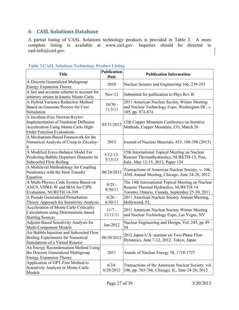
6 CASL Solutions Database A partial listing of CASL Solutions technology products is provided in Table 3. A more complete listing is available at www.casl.gov. Inquiries should be directed to [email protected].
Table 3 CASL Solutions Technology Product Listing
Title Publication Date Publication Information
A Discrete Generalized Multigroup Energy Expansion Theory 2010 Nuclear Science and Engineering 166, 239-253 A fast and accurate scheme to account for arbitrary strains in kinetic Monte Carlo Nov-12 Submitted for publication to Phys Rev B A Hybrid Variance Reduction Method Based on Gaussian Process for Core Simulation
10/30 - 11/3/11
2011 American Nuclear Society Winter Meeting and Nuclear Technology Expo, Washington DC, v. 105, pp. 872-874
A Jacobian-Free Newton-Krylov Implementation of Nonlinear Diffusion Acceleration Using Monte Carlo High-Order Function Evaluations
03/31/2012 12th Copper Mountain Conference on Iterative Methods, Copper Mountain, CO, March 26
A Mechanism-Based Framework for the Numerical Analysis of Creep in Zircaloy-4
2013 Journal of Nuclear Materials, 433, 188-198 (2013)
A Modified Force-Balance Model For Predicting Bubble Departure Diameter In Subcooled Flow Boiling
5/12/13-5/15/13
15th International Topical Meeting on Nuclear Reactor Thermalhydraulics, NURETH-15, Pisa, Italy, May 12-15, 2013, Paper 124
A Multilevel Methodology for Coupling Neutronics with the Heat Transfer Equation
06/24/2012 Transactions of American Nuclear Society, v. 106, ANS Annual Meeting, Chicago, June 24-28, 2012
A Multi-Physics Code System Based on ANC9, VIPRE-W and BOA for CIPS Evaluation, NURETH 14-399
9/25 - 9/30/11
The 14th International Topical Meeting on Nuclear Reactor Thermal Hydraulics, NURETH-14 Toronto, Ontario, Canada, September 25-30, 2011
A Pseudo Generalized Perturbation Theory Approach for Sensitivity Analysis
6/26 - 6/30/11
2011 American Nuclear Society Annual Meeting, Hollywood, FL
Acceleration of Monte Carlo Criticality Calculations using Deterministic-based Starting Sources
11/7 - 11/11/11
2011 American Nuclear Society Winter Meeting and Nuclear Technology Expo, Las Vegas, NV
Adjoint-Based Sensitivity Analysis for Multi-Component Models Jan-2012 Nuclear Engineering and Design, Vol. 245, pp 49-
54Air Bubble Injection and Subcooled Flow Boiling Experiments for Numerical Simulations of a Virtual Reactor
06/30/2012 2012 Japan-U.S. seminar on Two-Phase Flow Dynamics, June 7-12, 2012, Tokyo, Japan
An Energy Recondensation Method Using the Discrete Generalized Multigroup Energy Expansion Theory
2011 Annals of Nuclear Energy 38, 1718-1727
Application of GPT-Free Method to Sensitivity Analysis in Monte Carlo Models
6/24-6/28/2012
Transactions of the American Nuclear Society, vol. 106, pp. 763-766, Chicago, IL, June 24-28, 2012

Page 28 of 39 3/20/2013
Title Publication Date Publication Information
Application of the Discrete Generalized Multigroup Method to Ultra-Fine Energy Mesh in Infinite Medium Calculations
4/15 - 4/20/12
PHYSOR 2012 Conference: Advances in Reactor Physics, Knoxville, TN
Best-Estimate Model Calibration through First-Order Experimental Data Assimilation with Applications to Neutron Transport via Denovo
06/30/2012 2012 ANS Annual Meeting, Chicago, IL, June 24-28, 2012
CASL Multiphysics PWR Modeling Including Crud Induced Power Shift (CIPS) and Crud Induced Localized Corrosion (CILC)
09/04/2012 Top Fuel 2012 - ANS/ENS Fuel Performance Conference, Manchester, UK, Sept 2-6, 2012
CASL Validation Data: An Initial Review 01/31/2011 INL Publication, INL/EXT-11-21017 CASL Virtual Reactor Predictive Simulation: Grid-to-Rod Fretting Wear Aug-2011 Journal of the Minerals, Metals and Materials
Society, Vol. 63, No. 8CMFD Acceleration of Spatial Domain-Decomposed Neutron Transport Problems 04/15/2012 PHYSOR 2012, Knoxville, TN, April 15-20, 2012
Combining Partial Redundancy and Checkpointing for HPC
6/18/12-6/21/12
32nd International Conference on Distributed Computing Systems, Macau, China, June 18-21, 2012
Coupled Computational Fluid Dynamics and MOC Neutronic Simulations of Westinghouse PWR Fuel Assemblies with Grid Spacers, NURETH 14-254
9/25 - 9/30/11
The 14th International Topical Meeting on Nuclear Reactor Thermal Hydraulics, NURETH-14 Toronto, Ontario, Canada, September 25-30, 2011
Demonstration of validation methodology applied to VIPRE-W boiling index calculations
Apr-11 Los Alamos Report LA-UR-11-02470
Development of a Predictive Wear Model for Grid-to-Rod Fretting in Light Water Nuclear Reactors
2012 ASTM Selected Technical Papers (STP) Volume 1563, in press
DNS of Bubbly Flows in Vertical Channels
10/26/12-10/30/12
7th International Symposium on Multiphase Flow, Heat Mass Transfer and Energy Conversion (ISMF2012), Xi'an, China, October 26-30, 2012
Education Program for US DOE Nuclear Modeling and Simulation Hub - CASL Feb - 2011 Proceedings of the ANS Conference on Nuclear
Training and Education (CONTE) Effects of Li on Zirconium Alloy Corrosion - Li Insertion, and Ion Migration in ZrO2
11/28 - 12/2/2011
MRS Fall Meeting & Exhibit, Nov. 28-Dec. 2, 2011, Boston, MA
Efficient Transfer of Sensitivity Information in Multi-Component Models 5/8 - 5/12/11
International Conference on Mathematics and Computational Methods Applied to Nuclear Science and Engeineering (M&C 2011), Rio de Janeiro, Brazil
Evaluating PWR Fuel Performance Using Vessel CFD Analysis, Paper 017
9/26 - 9/29/10
Proceedings of 2010 LWR Fuel Perfomance/TopFuel/WRFPM Orlando, Florida, September 26-29, 2010, Paper 017
Evaluating Shear Induced Lift Force Using Interface Tracking Approach
11/11/12-11/15-12
ANS Winter Meeting, San Diego, CA, November 11-15, 2012

Page 29 of 39 3/20/2013
Title Publication Date Publication Information
Exact-to-Precision Generalized Perturbation Theory: Analytical Analysis
6/16-6/20/2013
Transactions of the American Nuclear Society, ANS 2013 Annual Meeting, Atlanta, GA, June 16-20, 2013
First Principles Analysis Revises Understanding of Self-Interstitial Configurations in HCP Zr
May-12 Submitted for publication to Philosophical Magazine Letters
First-Principles Assessment of the Reactions of Boric Acid on NiO (001) and ZrO2 (-111) Surfaces
Mar-12 J. Phys. Chem. C 116 (2012) 10113-10119
Flow Induced Vibration Forces on a Fuel Rod by LES CFD Analysis, NURETH 14-365
9/25 - 9/30/11
The 14th International Topical Meeting on Nuclear Reactor Thermal Hydraulics, NURETH-14 Toronto, Ontario, Canada
Gaussian Process Approach for Global Variance Reduction
6/26 - 6/30/11
2011 American Nuclear Society Annual Meeting, Hollywood, FL
Generalized Hybrid Monte Carlo-CMFD Methods for Fission Source Convergence 5/8 - 5/12/11
International Conference on Mathematics and Computational Methods Applied to Nuclear Science and Engeineering (M&C 2011), Rio de Janeiro, Brazil
Generalized Perturbation Theory-Free Sensitivity Analysis for Eigenvalue Problems
August 2012 Nuclear Technology, v. 179, no. 2, pp. 169-179, August 2012
Heuristic Approach for ESM-based Reduced Order Modeling
10/30 - 11/3/11
2011 American Nuclear Society Winter Meeting and Nuclear Technology Expo, Washington DC
Highly-resolved LES of turbulent convective flow and heat transfer along a PWR rod bundle
5/12/13-5/17/13
Proc. 15th International Topical Meeting on Nuclear Reactor Thermalhydraulics (NURETH-15), Pisa, Italy, May 12-17, 2013
High-Order Response Moments for Model Uncertainty Quantification and Validation
06/30/2012 2012 ANS Annual Meeting, Chicago, IL, June 24-28, 2012
Hybrid and Parallel Domain-Decomposition Methods Development to Enable Monte Carlo for Reactor Analyses
2011 Progress in Nuclear Science and Technology, Accepted for publication, 2011
Hybrid deterministic/monte carlo neutronics using {GPU} accelerators 06/07/2012
2012 International Symposium on Distributed Computing and Applications to Business, Engineering and Science, Q. Guo and C. Douglas, eds., Los Alamitos, CA, 2012, IEEE, pp. 43-47.
Hybrid Monte Carlo-Deterministic Methods for Reactor Analysis Dec-12 Nuclear Technology, v. 180, pp. 372-382,
December 2012Hybrid Uncertainty and Sensitivity Algorithms for High Dimensional Nonlinear Models, Part I: Introduction to the Theory
2010 2010 American Nuclear Society Winter Meeting and Nuclear Technology Expo, Las Vegas, NV, v. 103, pp. 375-377
Hydraulic Benchmark Data for PWR Mixing Vane Grid 2011
14th International Topical Meeting on nuclear Reactor Thermal Hydraulics (NURETH 14), September 25-29, Ontario, Canada, 2011 and published in the conference proceedings, 2011.

Page 30 of 39 3/20/2013
Title Publication Date Publication Information
Influence of Bubbles on the Turbulence Anisotropy 2013 Accepted to Journal of Fluids Engineering Intrinsic point-defect equilibria in tetragonal ZrO2: Density functional theory analysis with finite-temperature effects
2012 2012 American Physical Society, Physical Review B, v. 86, 144109
Inverse Relation between Strain Rate and Yield Strength of Dislocation -Obstacle Interaction in bcc Fe
11/25/12-11/30/12
MRS Fall Meeting & Exhibit, Nov. 25-30, 2012, Boston, MA
Large-Eddy Simulations of Turbulent Flow for Grid-to-Rod Fretting in Nuclear Reactors
2013 Nuclear Engineering and Design (under review)
Large-Scale Turbulent Simulations of Grid-To-Rod Fretting
9/10/12-9/12/12
The Experimental Validation and Application of CFD and CMFD Codes in Nuclear Reactor Technology (CFD4NRS-4), OECD/NEA and IAEA Workshop, Korea Atomic Energy Research Institute (KAERI), Daejeon, Korea, Sept. 10-12, 2012
Light Water Reactor Fuel Performance Modeling and Multi-Dimensional Simulation
Aug-2011 Journal of the Minerals, Metals and Materials Society, Vol. 63, No. 8
LIME: Lightweight Integrated Multiphysics Environment
7/12 - 7/16/10
2010 Society for Industrial and Applied Mathematics (SIAM) Annual Meeting, Pittsburgh, PA, July 12-16, 2010, SAND2010-4810C
Managing dimension and complexity in surrogate modeling 2/28 - 3/4/11 2011 SIAM Conference on Computational Science
and Engineering (CSE11), Reno, NV Massively Parallel Solutions to the k-Eigenvalue Problem. 2010
Transactions of the American Nuclear Society, Vol 103. ** Winner, Best paper ANS 2010 Winter Meeting
Mechanical degradation of ZrO2 passive layer in the presence of hydrogen defects
11/25/12-11/30/12
MRS Fall Meeting & Exhibit, Nov. 25-30, 2012, Boston, MA
Mechanism of Void Nucleation and Growth in bcc FE: Atomistic Simulations at Experimental Time Scales
03/21/2011 2011 American Physics Society, Physical Review Letters 106, 125501
Method for Improving Deposition (CRUD) Resistance of Nuclear Fuel Cladding and Components
2012 USPTO #61/600, 128 (Patent)
Microstructural Evolution of Irradiated Materials: Kinetics at Long Time Scales; Self Interstitial Clusters, Vacancy Clusters, Dislocations
Mar - 2011Penn State University, Mechanical and Nuclear Engineering Department Colloquium, State College, PA
Multidimensional Modeling of Interfacial Boiling and Condensation 11/03/2012 2011 ANS Winter Meeting, Washington, DC, Oct
30-Nov 3, 2011Multiphysics Coupling Via LIME: Lightweight Integrated Multiphysics Environment
2/28 - 3/4/112011 SIAM Conference on Computational Science and Engineering (CSE11), Reno, NV, SAND2011-1425C

Page 31 of 39 3/20/2013
Title Publication Date Publication Information
Multiscale Issues in DNS of Multiphase Flows
7/24 - 7/29/11
AJK2011-04004: ASME-JSME-KSME Joint Fluids Engineering Conference 2011, Hamamatsu, Shizuoka, Japan
On the Development of Parallel Linear Solvers for Simulations of Reactor Thermal hydraulics
9/25 - 9/30/11
The 14th International Topical Meeting on Nuclear Reactor Thermal Hydraulics, NURETH-14 Toronto, Ontario, Canada, September 25-30, 2011
On the Effects of Orientation Angle, Subcooling, Mass Flux, Heat Flux, and Pressure on Bubble Departure Diameter in Subcooled Flow Boiling
9/10/12-9/12/12
The Experimental Validation and Application of CFD and CMFD Codes in Nuclear Reactor Technology (CFD4NRS-4), Daejeon, Korea, Sept. 10-12, 2012
On the modeling of gas/liquid flows using DNS
6/26 - 6/30/11
2011 American Nuclear Society Annual Meeting, Hollywood, FL, June 26-30, 2011
On the Propagation of Uncertainties in High Dimensional Models
10/30 - 11/3/11
2011 American Nuclear Society Winter Meeting and Nuclear Technology Expo, Washington DC
On the Turbulence Modeling in Bubbly Gas/Liquid Flows 2012 Advances in Thermal Hydraulics, November 11-
15, 2012, San Diego, CA Parallel Fission Bank Algorithms in Monte Carlo Criticality Calculations Feb-12 Nuclear Science and Engineering, v. 170, no. 2, pp.
125-135, Feb. 2012
Parallel linear solvers for simulations of reactor thermal hydraulics
9/25/11-9/29/11
The 14th International Topical Meeting on Nuclear Reactor Thermal Hydraulics (NURETH-14), Toronto, Ontario, Canada, September 25-29, 2011
Parameter Sensitivity Study of Boiling and Two-Phase Flow Models in Computational Thermal Hydraulics
9/25/11-9/30/11
14th International Topical Meeting on nuclear Reactor Thermal Hydraulics (NURETH 14), September 25-29, Ontario, Canada, 2011 and published in the conference proceedings, 2011.
Pressurized Water Reactor Fuel Crud and Corrosion Modeling Aug-2011 Journal of the Minerals, Metals and Materials
Society, Vol. 63, No. 8Progress in the large-scale simulation of convective boiling heat transfer under turbulent conditions using TransAT
7/29/13-8/2/13
Proc. ICONE21, July 29-August 2, 2013, Chengdu, China
RANS Modeling for Flow in Nuclear Fuel Bundle in Pressurized Water Reactors (PWR)
2011 Nuclear Engineering and Design Journal, Vol. 241, Issue 11, pp. 4404-4408, 2011.
Reactor Core Sub-Assembly Simulations Using a Stabilized Finite Element Method
9/25 - 9/30/11
The 14th International Topical Meeting on Nuclear Reactor Thermal Hydraulics, NURETH-14 Toronto, Ontario, Canada, September 25-30, 2011
Reduced Order Modeling for Multi-Physics Problems
11/11-11/15/2012
Transactions of the American Nuclear Society, v. 107, pp. 586-588, San Diego, CA, November 10-15, 2012.
Simulation of Subcooled Boiling using CMFD 06/30/2012 ANS Student Conference, Las Vegas, NV, April
13-15, 2012State-Based Adjoint Approach for Reduced Order Modeling Jan-2012 Journal of Transport Theory and Statistical Physics
Statistical analysis of interface tracking simulations informs the development of multiphase CFD models
06/30/20122012 International Congress on Advances in Nuclear Power Plants , Chicago, IL, June 24-28, 2012

Page 32 of 39 3/20/2013
Title Publication Date Publication Information
Stochastic Higher-Order Generalized Perturbation Theory for Neutron Diffusion and Transport Calculations
7/29-8/2/2013
Proceedings of the 2013 21st International Conference on Nuclear Engineering (ICONE21), July 29-August 2, 2013, Chengdu, China
Strain Rate Effects on the Mechanism of Dislocation Interactions with Self-Interstitial Atom Clusters in Zirconium
11/28 - 12/2/2011 MRS Fall Meeting 2011, Boston, MA
Subcooled Flow Boiling Experiment and Simulation for a Virtual Reactor
9/25 - 9/30/11
The 14th International Topical Meeting on Nuclear Reactor Thermal Hydraulics, NURETH-14 Toronto, Ontario, Canada
Temperature and Strain Rate Effects on the Interaction Mechanisms between Edge Dislocation and Self-interstitial Atom Clusters in Zr
10/15/12-10/19/12
6th International Conference on Multiscale Materials Modeling (MMM 2012), Biopolis, Singapore, October 15-19, 2012
Theoretical Investigation of Microstructure Evolution and Deformation of Zirconium under Cascade Damage Conditions
Jun-12 ORNL Report, ORNL/TM-2012/225
Thermal Conductivity of UO Fuel: Predicting Fuel Performance from Simulation
Aug-2011 Journal of the Minerals, Metals and Materials Society, Vol. 63, No. 8
Time-Scale Bridging in Atomistic Simulation of Slow Dynamics: Viscous Relaxation and Defect Activation
2011 The European Journal of Physcis B82, 271-293
Toward Mechanistic Modeling of Boiling Heat Transfer 2012 Nuclear Engineering and Technology, v. 44, no. 8,
pp. 889-896, December 2012 Verification Tests for Uncertainty and Sensitivity Analysis Studies
10/30 - 11/3/11
2011 American Nuclear Society Winter Meeting and Nuclear Technology Expo, Washington DC
Virtual Office Community and Computing (VOCC); Designing an Energy Science Hub Collaboration System
07/14/2011
Human Computer Interaction (HCI) International Conference. Presentation published by Springer in a multi-volume set in the Lecture Notes in Computer Science (LNCS), the Lecture Notes in Artificial Intelligence (LNAI) series, and the Communications in Computer and Information Science (CCIS) series
Virtualizing Energy; The Need for Engineering Computer Centers & Virtual Presence
06/16/2011 National Laboratories IT Summit (NLIT), 6/14-6/17, Golden, CO
Waterside Corrosion in Zirconium Alloys Aug-2011 Journal of the Minerals, Metals and Materials Society, Vol. 63, No. 8

Page 33 of 39 3/20/2013
7 Technology Delivery An important consideration for CASL is the delivery of its technology to current and potential users throughout the nuclear energy enterprise. CASL is committed to early and regular delivery of VERA, with functionality evolving based on iterative feedback with those receiving and applying/testing the technology. The following sections discuss the transfer of CASL technologies through ModSim product distributions, Test Stand installations, Pilot projects, and Education and Training initiatives.
7.1 CASL ModSim Product Distributions VERA and its associated applications will be available to qualified users via an established release center (process to be established in the future). CASL will periodically issue software applications releases that will be made available for wide distribution, with the initial distribution completed in 2012. Each release will include basic generic inputs and geometries needed to solve basic simulations to the extent to which the technology has been developed at the time of the release. Sufficient tutorials will be provided to allow the user to navigate the software application with or without expert guidance, depending upon the maturity of the release. The level of maturity of each release will be provided through objective benchmark reporting within the release documentation, such that Users are informed of the areas of technology that are mature and others that need to be further developed.
7.2 Test Stands Test Stands are defined as targeted deployments of CASL’s ModSim product on smaller scale computational platforms for alpha testing by CASL Partner users. The Test Stand will be used to study specific challenge problems and to demonstrate and apply the ModSim capabilities. As the maturity level of the capability is advanced, users outside of the CASL Consortium partnership may host test stands as well. The deployment of Test Stands is expected to allow for User feedback on usability and effectiveness the technology, will generate expert Users of the technology at the industrial level, and may expand the validated range of the technology.
7.3 Pilot Projects Pilot projects will be used to study industry issues and facilitate power uprates utilizing DOE’s HPC capabilities and CASL’s expert staff. The studies will target interaction with CASL Industry Council members and other potential Users to develop familiarity and support for CASL technologies. Pilot projects are expected to coincide with CASL development initiatives; this ensures that the Pilot project benefits the development effort as a whole and minimizes the impact on project staff and funding. Studies provide visibility for the CASL technology, direct demonstration of CASL technology, and additional validation for the physics models applied within the CASL technology.
7.4 Education and Training The CASL education and training objective is to educate today’s reactor designers in the use of advanced ModSim through training course and direct engagement in CASL activities, and to develop the next generation of engineers and scientists at all levels through new curricula at

Page 34 of 39 3/20/2013
universities. The CASL education and training effort is the first of its kind to develop new curricula and programs in nuclear energy at the graduate level based on the ModSim technologies developed by CASL. The CASL education and training strategy is being carried out with the following elements:
• Promoting diversity and excellence among the nuclear engineering student population with active recruiting of top students at the undergraduate and graduate levels, underrepresented minorities and women to higher levels, and interdisciplinary students;
• Mapping the CASL Challenge Problems into existing graduate course curricula;
• Developing new chapter modules for courses based on CASL Challenge Problem course materials;
• Developing and executing an industry education knowledge transfer plan;
• Developing a template of courses for a new certificate in nuclear systems design; and
• Executing annual programs for undergraduate scholars and graduate student interns.

Page 35 of 39 3/20/2013
8 CASL’s Future Products The foundational ModSim technology established in CASL’s first 5 years represents a significant investment in sophisticated technological advances that have the potential to revolutionize commercial nuclear power production. The coupled capabilities of the ModSim approach have wide applications within the nuclear energy enterprise, and given the modular approach adopted by CASL, are expandable.
Given the focus of the first 5 years on development of PWR quasi-steady state reactor core simulation capabilities, a logical expansion of the ModSim technology puts a focus on BWR core simulation, reactor aging, transients and accident simulation, severe accident simulation, and systems capabilities. The inclusion of these additional capabilities rounds out the foundational and challenge problem capabilities of the full 3D higher fidelity multi-physics ModSim technology and provides the set of simulation needs described in Table 1. For discussion purposes, Table 4 provides a possible set of focal models and coupled capabilities that could be targeted for a second 5 year CASL development program.
In addition to the focal targets necessary to complete the foundational and challenge problem capabilities, it is important to address the needs of the next generation of nuclear power reactors. In order to ensure future compatibility of the ModSim technology, it is important to integrate the ability to model approved new designs (e.g., AP1000, EPR, iPWRs) and higher probability accident tolerant fuel designs (those funded for research by DOE). Thus, next generation development objectives have been included in Table 4 for discussion.

Page 36 of 39 3/20/2013
Table 4 Evolution of CASL’s ModSim Technology
Completed in the First 5 years
Suggested for Development during Second 5 years
Suggested Development Scope for the Next Generation Nuclear
Power Generation
Foun
datio
nal C
oupl
ed C
apab
ility
T-H: Local axial and cross flow; Local coolant temperature and density; Core pressure drop and lift loads; Pressure drop across components; holddown spring and net loads; Coolant mixing/turbulence; Bypass mass flow; Neutronics: Local neutron flux; Fuel Rod Performance: Local rod surface temperature; Pellet temperature; fuel rod internal pressure Cladding stress/strain Rod Oxidation and hydriding; Pellet and cladding dimensions; Pellet/clad interaction status and local stress/strain, pellet relocation effects Coupling: Coupling of fluid, heat transfer, neutronics and rod performance models; Ability to model grids discretely within neutronics and Thermal-hydraulics; Azimuthal cladding and pellet temperatures;
T-H: Inclusion of multi-phase flow predictions for transients and BWRs; Calculation of DNBR/margin Neutronics: BWR geometry; Fast transient capability; Add capability to calculate reactor and fuel structure doses; Fuel Rod Performance: Clad plasticity models to predict balloon & burst for LOCA; Clad microstructure studies Improved transient performance; Inclusion of crack propagation models for cladding; Oxidations kinetics for severe accidents;Thermal stress, quench performance; Rapid transient modeling capability; Seismic impact performance; Rod bow performance; Assembly distortion performance & control rod drop time prediction; Improved rod performance visualization; Systems: Upgraded systems tool; Seismic/LOCA structural performance (fuel and vessel); Coupling: Tightened VERA coupling, as needed; Improved boundary condition treatments;Coupling of Systems tool; Standardize materials libraries across VERA as possible
Next Generation Reactors: Establish generic mesh for simulation of:
GenIII+ PWR; GenII & GenIII+ BWR; SMR (iPWR)
Accident Tolerant Fuel: Standard meshed virtual models for advanced reactor and fuel geometries; Ability to model non-standard geometry and materials; Addition of general material models for selected fuel and clad materials, including:
clad oxidation kinetics and high temperature performance; Pellet densification and swelling model; Fission gas release model; Pellet crack/relocation model; Pellet thermal conductivity as a function of burnup; Clad and structure thermal and irradiation creep models.
Develop ModSim approach to address non-ductile clad materials, as needed; Develop ModSim approach to address metal fuels as needed; Develop ModSim approach to address non-rod geometries, as needed;

Page 37 of 39 3/20/2013
Completed in the First 5 years
Suggested for Development during Second 5 years
Suggested Development Scope for the Next Generation Nuclear
Power Generation
Cha
lleng
e Pr
oble
m T
ool C
apab
ility
Coolant Chemistry: Mechanistic chemistry deposition models; Coupled with neutronics & T-H; GTRF: Structure/rod vibration characteristics including vibration frequency & amplitude; Improved wear models; Improved fluid-structure interaction modeling approach; Wear depths. Coupled GTRF tool with rod performance and VERA; PCI: Higher fidelity 3D clad stress/strain based on higher fidelity rod performance calculations; Maneuvering performance assessment capability; Coupled ability to analyze missing pellet surfaces and prediction of localized stress and strain; Coupled through VERA base capability Systems: Basic systems code available.
Coolant Chemistry: Improve Reactor CRUD inventory through systems tool leverage. Reactor Aging: Structure/Joint/nozzle stress & strain; chemistry tool to address SCC and NSSS corrosion; Crack propagation models; GTRF & FAD: Fuel Assembly structure/rod oxidation and hydriding PCI: Add chemistry effects to support classical PCI simulation
Severe Accidents: Add capability to predict core melt and relocation.
Mod
Sim
App
roac
h
Highest fidelity capability using full 3D models with HPC platform and higher fidelity capability using reduced resolution models with industry-compatible platform. Submodeling capability to zoom in on areas of interest; Improved uncertainty estimate capability; Standard geometry and material libraries; Integral uncertainty quantification Steady state single phase at specific time steps within the reactor cycle and transient single phase to the current capabilities of the codes included.
Continue to leverage HPC platform for highest fidelity solutions; build IC platform capabilities through parallelization and streamlined analytical approaches.
Integrate ATF to foundational tools; create base models and mesh for Next Gen reactors; increase leverage and coupling of systems tool to address severe accidents.

Page 38 of 39 3/20/2013
9 References 1. D. Kothe et. al., CASL Program Plan, Revision 4.0, Consortium for Advanced
Simulation of LWRs, Oak Ridge National Laboratory, 9/20/12. 2. J.A.Turner, VERA 2.3 Snapshot Report, L2:VRI.P6.01 12/19/2012, Consortium for
Advanced Simulation of LWRs, Oak Ridge National Laboratory, 01/31/2013. 3. J.A. Turner et. al., ASCR Leadership Computing Challenge (ALCC) Request,
Consortium for Advanced Simulation of LWRs, Oak Ridge National Laboratory, 01/31/2013.
4. CASL Denovo Wiki, Oak Ridge National Laboratory, 2012. 5. SCALE: A Comprehensive Modeling and Simulation Suite for Nuclear Safety
Analysis and Design, ORNL/TM-2005/39, Version 6.1, Oak Ridge National Laboratory, Oak Ridge, TN (June 2011). Available from Radiation Safety Information Computational Center at Oak Ridge National Laboratory as CCC-785.
6. M. Christon, Hydra-TH Theory Manual, Los Alamos National Laboratory, 2011. 7. The Dakota project, Sandia National Laboratory, retrieved 2/2013, from
http://dakota.sandia.gov/. 8. B. Collins, MPACT User Manual v1.0.0, University of Michigan, Ann Arbor, January
18, 2013. 9. Cobra-TF Users Manual, Pennsylvania State University, 2012. 10. R. Schmidt, N. Belcourt, R. Hooper, and R. Pawlowski, An Introduction to LIME 1.0
and its Use in Coupling Codes for Multiphysics Simulations. Sandia Technical Report SAND2011-8524, Sandia National Laboratories, Nov 2011.
11. R. Pawlowski, R. A. Bartlett, N. Belcourt, R. Hooper, and R. Schmidt. A theory manual for multi-physics code coupling in LIME. Sandia Technical Report SAND2011-2195, Sandia National Laboratories, March 2011.
12. R. Adamson et. al., Zirat 15 Annual Report, Advanced Nuclear Technology International, Skultuna, Sweden, 2010.
13. J. Secker and P. Turinsky, CASL CRUD CP Implementation Plan (draft), Consortium for Advanced Simulation of LWRs, Oak Ridge National Laboratory, 1/2013.
14. Wang, G.; Byers, W.A.; Karoutas, Z.E.; Young, M.Y.; Jacko, R.J. [WEC]; Hochreiter, L.E. [Penn. State Univ.], “Single Rod Heat Transfer Tests to Study the Effects of Crud Deposition,” 14th Intl. conf. on nuclear engineering (ICONE 14), 17-20 Jul 2006.
15. G. Wang, W. A. Byers, M. Y. Young, and Z. E. Karoutas, “Westinghouse Advanced Loop Tester (WALT) Update,” ASME Conf. Proc. 2008, 469 (2008), DOI:10.1115/ICONE16-48480.
16. Z. Karoutas, CFD Turbulence Force Calculations and Grid-to-Rod Fretting Simulation (CASL-I-2012-0135-000) , Consortium for Advanced Simulation of LWRs, Oak Ridge National Laboratory, 12/15/2012.
17. R. Adamson et. al., Zirat 12 Annual Report, Advanced Nuclear Technology International, Skultuna, Sweden, 2007.
18. R. Adamson et. al., Zirat 11 Annual Report, Advanced Nuclear Technology International, Skultuna, Sweden, 2006.

Page 39 of 39 3/20/2013
19. Electric Power Research Institute, Fuel Reliability Database (FRED) Version 3.4, Copyright 2004-2012 .
20. IAEA-TECDOC-1345, Fuel failure in water reactors: Causes and mitigation Proceedings of a Technical Meeting held in Bratislava, Slovakia, 17–21 June 2002.
21. IAEA-TECDOC-1454 Structural behaviour of fuel assemblies for water cooled reactors Proceedings of a technical meeting held in Cadarache, France, 22–26 November 2004.
22. International Atomic Energy Agency, IAEA NUCLEAR ENERGY SERIES No. NF-T-2.1, VIENNA, 2010.
23. Z. Karoutas, D. Mitchell and J. Gehin, AMA discussion of Peregrine/PCI implementation (Powerpoint presentation), MPO/PCI Meeting at ORNL, Consortium for Advanced Simulation of LWRs, Oak Ridge National Laboratory, January 11, 2012.
24. L2:MPO.P5.03, R.O. Montgomery et. al., Peregrine: Initial Verification and Benchmark Evaluations against Halden Fuel Rod Data and Falcon, August 2012.
25. R. Williamson, J. Hales, S. Novascone, M. Tonks, D. Gaston, C. Permann, D. Andrs, and R. Martineau, “Multidimensional multiphysics simulation of nuclear fuel behavior,” Journal of Nuclear Materials 423(2012) 149-163.
26. D. Gaston, C. Newman, G. Hansen, and D. Lebrun-Grandie ́. MOOSE: A parallel computational framework for coupled systems of nonlinear equations. Nucl. Eng. Design, 239, p. 1768–1778, 2009.
27. Fuel Analysis and Licensing Code: Falcon MOD01: Volume 1: Theoretical and Numerical Bases, EPRI, Palo Alto, CA: 2004. 1011307.