casl: consortium for the advanced simulation of light
TRANSCRIPT

1
CASL: Consortium for the Advanced Simulation of Light Water Reactors
Update on Grid to Rod Fretting (GTRF)Challenge Problem Activities
Brian Wirth, GTRF CPIon behalf of Peter Blau, David Parks, Ken Kamrin, Wei Lu, Anirban
Patra, Michale Thouless, Carlos Tome, and Jun Qu
CASL SC/IC meeting11 October 2016
ORNL
2
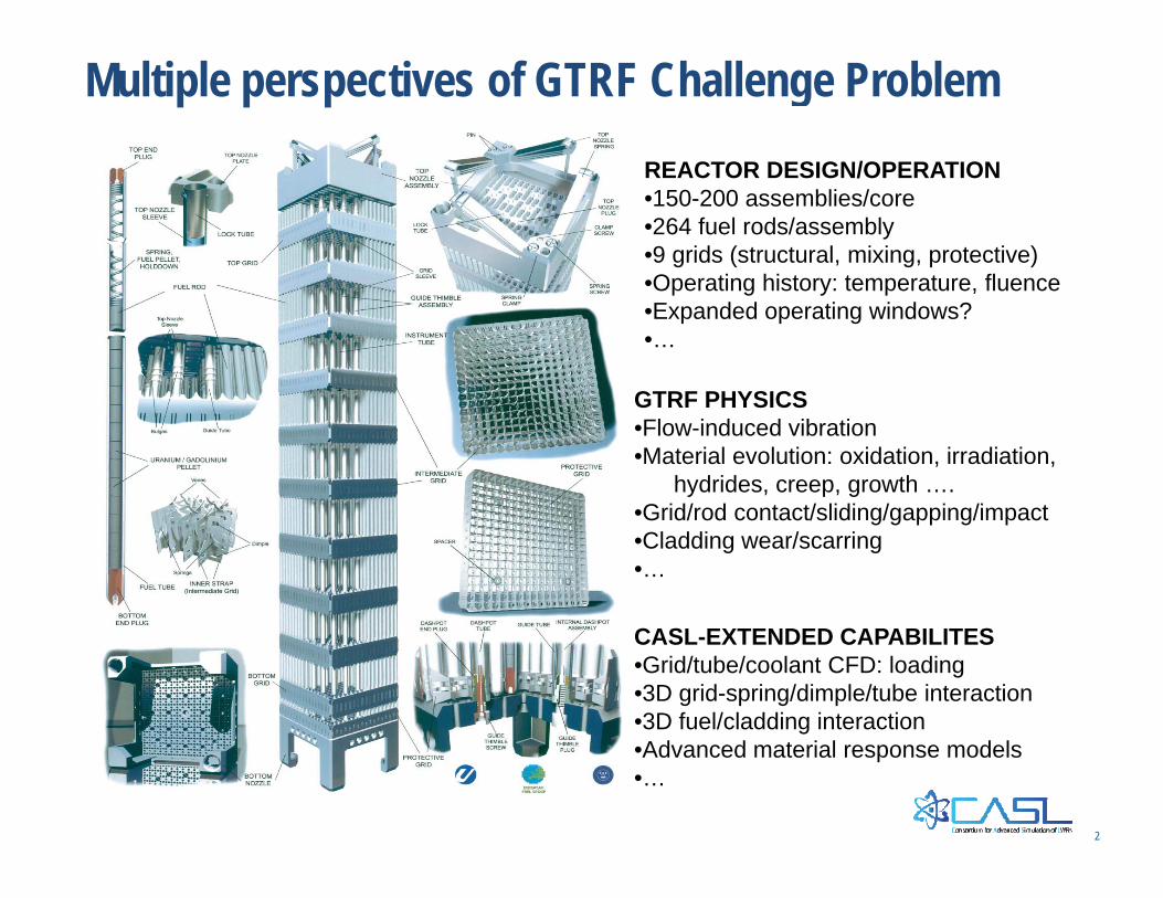
Multiple perspectives of GTRF Challenge ProblemREACTOR DESIGN/OPERATION•150-200 assemblies/core•264 fuel rods/assembly•9 grids (structural, mixing, protective)•Operating history: temperature, fluence•Expanded operating windows?•…
GTRF PHYSICS•Flow-induced vibration•Material evolution: oxidation, irradiation,
hydrides, creep, growth ….•Grid/rod contact/sliding/gapping/impact•Cladding wear/scarring•…
CASL-EXTENDED CAPABILITES•Grid/tube/coolant CFD: loading•3D grid-spring/dimple/tube interaction•3D fuel/cladding interaction•Advanced material response models•…
3
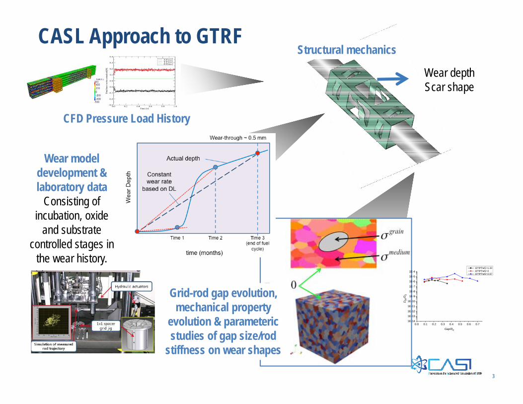
Structural mechanics CASL Approach to GTRF
Wear depthScar shape
CFD Pressure Load History
Grid-rod gap evolution, mechanical property
evolution & parametericstudies of gap size/rod
stiffness on wear shapes
Wear model development & laboratory data
Consisting of incubation, oxide
and substrate controlled stages in
the wear history.
0.0 0.1 0.2 0.3 0.4 0.5 0.6 0.71E-14
1E-13
1E-12
1E-11
1E-10
1E-9
1E-8
1E-7
1E-6
1E-5
1E-4
Dm
/Dc
Gap/Dc
10^8*Pa/E=1.33 10^8*Pa/E=2 10^8*Pa/E=2.67

4
Fretting mechanics: recent progress on modeling wear
David Parks (MIT) is developing sub-modeling approaches to reduce computational degrees of freedom, while driving relative motions based on beam histories, and beginning to predict representative wear shapes and volumes
Wei Lu and Michael Thouless(UMichigan) are evaluating coupled wear and creep effects

5
Fretting mechanics: recent progress on beam interactions
51 49 52 74
48 51 49 73
48 51 50 60
68 62 64 97
49 51 51 70
58 48 52 78
51 59 52 72
76 57 61 97
57 50 45 78
53
43
47
59
53
Average maximum wear-work compared to average maximum wear-workOf a single rod (no interactions) (in %)
IN THESE MODEL SYSTEMS, Intrinsic support stiffness bias in grid support stiffness(spring side vs dimple side) Leads to meaningful differences in mean maximum
wear-work rates among the population of tubes in the assemblage…
6
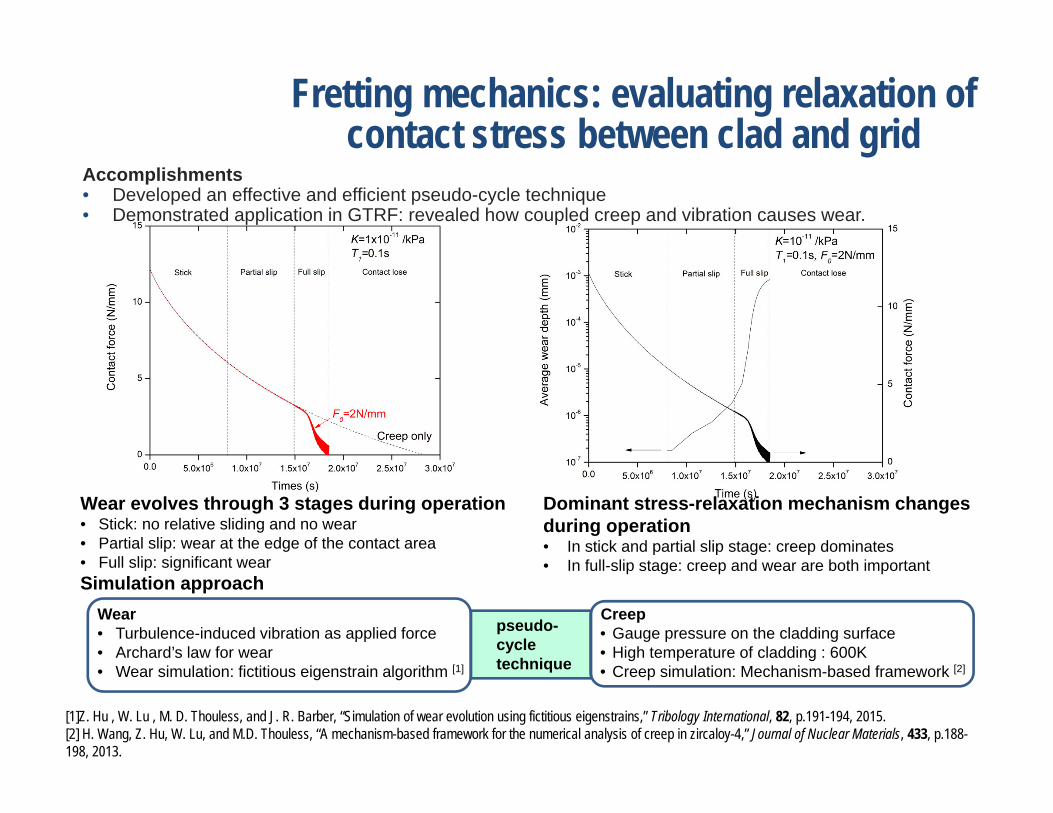
Fretting mechanics: evaluating relaxation of contact stress between clad and grid
Creep• Gauge pressure on the cladding surface• High temperature of cladding : 600K• Creep simulation: Mechanism-based framework [2]
Wear• Turbulence-induced vibration as applied force• Archard’s law for wear• Wear simulation: fictitious eigenstrain algorithm [1]
Wear evolves through 3 stages during operation• Stick: no relative sliding and no wear• Partial slip: wear at the edge of the contact area• Full slip: significant wearSimulation approach
Dominant stress-relaxation mechanism changes during operation• In stick and partial slip stage: creep dominates• In full-slip stage: creep and wear are both important
[1]Z. Hu , W. Lu , M. D. Thouless, and J. R. Barber, “Simulation of wear evolution using fictitious eigenstrains,” Tribology International, 82, p.191-194, 2015.[2] H. Wang, Z. Hu, W. Lu, and M.D. Thouless, “A mechanism-based framework for the numerical analysis of creep in zircaloy-4,” Journal of Nuclear Materials, 433, p.188-198, 2013.
pseudo-cycle technique
Accomplishments• Developed an effective and efficient pseudo-cycle technique• Demonstrated application in GTRF: revealed how coupled creep and vibration causes wear.

7
Engineering Wear Model
1. Assumes linear fretting motion.
1. Wear occurs in stages, each with its own material-based wear coefficient.
2. Frictional work / unit area is the source of energy to generate material damage, including wear.
3. A wear factor Wf, reflects the efficiency by which a given quantity of frictional work is converted into particles (wear debris).
4. Focus is mainly on the cladding, but work done in wearing the grid material reduces that available to wear the cladding.

8
High frequencies of impact and large oscillation amplitudes
increase the wear rate.
Engineering Wear Model developmentFactors like Normal Force, Frequency and Amplitude of Sliding Contact Affect GTRF
If normal force is either too high or two low, fretting is reduced or stopped.

9
Fretting mechanics: recent progress
• 3-D FEA model using dynamic explicit code
• Rod and spring/dimple material: Zircaloy-4
• Rod modeled with length 356 mm • Spring/two dimples modeled from
scanned profile• Contact defined between clad and
spring/ dimples surfaces• Initial velocity of clad upon impacting
spring/dimples estimated as 0.25~0.62mm/s
Impact FEA simulated reaction force (N)
Rod against spring 0.08 ~ 0.16Rod against dimple 0.17 ~ 0.40
Rod-dimplesRod-spring
Used to define the specs of contact forces in bench tests.
Finite element modeling used to evaluate and refine design for new fretting tester under procurement

10
New autoclave fretting-impact wear (AFIW) tester designed & in-fabrication
• First-ever bench tester to generate GTRF wear rate data in a realistic environment • Results to be correlated with those of industrial dynamometer tests (cost >$100,000 per test)
Video below shows the prototype providing desired motion.Phoenix Tribology LTD, G . Plint
Parameter Impact + FrettingSpecimens Actual rod and grid sections
from WECContact and motion Fretting only, impact only, and
fretting+impactPressure vessel size Diameter < 4 inchesWater temperature RT – 220 CFluid pressure 1 – 24 barsNormal force (spring-loaded specimens)
0.1-1 N, calibrated by sensors prior to test
Tangential force Measured during RT testsAmplitude of oscillation 20 – 200 µmFrequency 20 – 60 HzInclined contact adjustable angle
*Machine to be delivered in Nov 2016.

11
Modeling gap development Irradiation growth due to
absorption of radiation‐induced point defects and climb of dislocations loops
Irradiation creep due to irradiation‐induced de‐pinning of line dislocations
Coupled growth and creep modeled at the level of grains in a polycrystalline aggregate using VPSC
Accounts for the effects of texture and grain interactions on the deformation behavior
VPSC interfaced with finite element codes to study the texture‐dependent deformation behavior at the component level
Simulation of gap opening between the cladding tube and spacer grid

12
Modeling gap development Tube dimensions: OD = 9.5 mm, ID = 8.357 mm, Length = 38 mm Spacer grid dimensions: Side = 12.598 mm, Thickness = 0.229 mm, Length =
38.1 mm Spacer grid mesh courtesy Wei Lu (U. Mich.) ≈ 50,000 8‐node reduced integration elements Material: Zircaloy‐2 Clad texture: Reduced texture with 7 grains Spacer texture: Reduced texture with 13 grains Clad texture rotated from hoop, radial, axial to
Cartesian axes Spacer texture rotated from normal, transverse,
rolling to Cartesian axes
Hard contact b/w spacer and clad SHRINK parameter in ABAQUS used to resolve
initial contact overclosures This allows for initial contact pressure build‐up b/w
the clad and the springs and dimples
Nodes constrained in all DOFs
Bottom node set of cladding tube constrained in z-dir
Clad texture Spring texture
Tube external pressure = 15.5 MPaTube internal pressure = 10 MPa

13
Distribution of pressure in springs & dimples
0 dpa: Pressure distribution similar on the springs and dimples 10.29 dpa: Contact pressures increase; dimples near the top more in contact than those at the
bottom; rotation of cladding tube about the spring plane 20 dpa: All springs and dimples out of contact
Pressure evolves differently in each of the springs and dimples
Simulated max. contact force:
Spring: 0.84 N Dimple: 1.72 N
Contact forces in the same range as other experimental and modeling studies
Spring
Dimple
Dimple

14
Spring deformation
14
Side view of dimple edge
Dimple edge deforms asymmetrically
Strain vectors on springs and dimples consistent with texture
Springs and dimples contract inwards, expand laterally
1: X, 2: Y, 3: Z
15
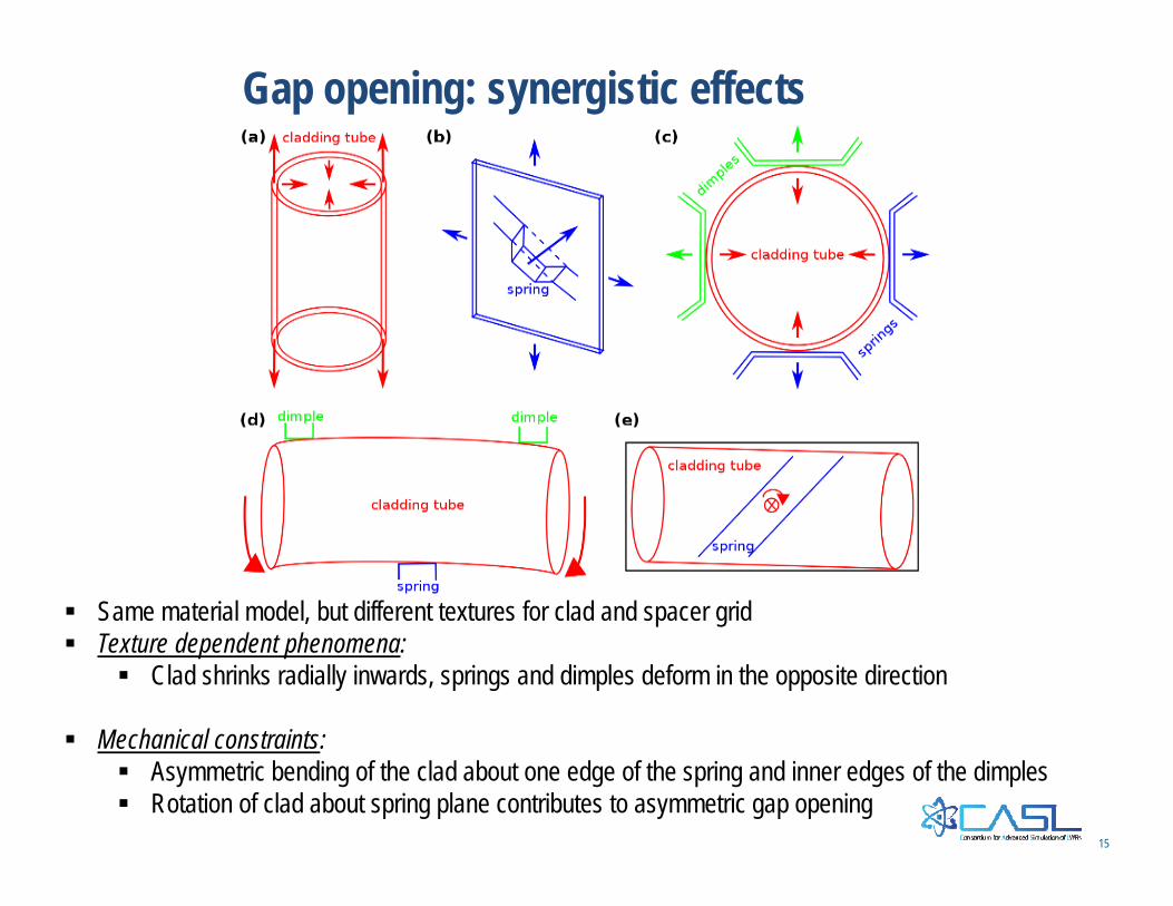
Gap opening: synergistic effects
Same material model, but different textures for clad and spacer grid Texture dependent phenomena:
Clad shrinks radially inwards, springs and dimples deform in the opposite direction
Mechanical constraints: Asymmetric bending of the clad about one edge of the spring and inner edges of the dimples Rotation of clad about spring plane contributes to asymmetric gap opening

16
Quantitative measure of gap opening
Δ(Gap) dpa
Gapdpa = <COPEN>dpaΔ(Gap) dpa = Gapdpa ‐ Gap0 dpa
Contact surface
COPEN variable used to estimate gap COPEN: Contact opening distance between
nearest nodes on the two contact surfaces <COPEN>dpa : Average over all nodes
comprising the contact surface of spring/ dimple
Gapdpa : Non‐zero at the beginning, since all nodes not in contact
Δ(Gap)20 dpa: Contribution of irradiation growth and creep to gap opening under steady state conditions
Spring 1: 15.1 μm Dimple 2: 29.3 μm Dimple 3: 30.3 μm
From analytical calculations (Billerey, IAEA‐TECDOC‐1454, pp. 101‐111, 2005): gap opening at end of life = 10 μm
GTRF wear setups generally use displacement amplitudes in the range 5‐30 μm
17
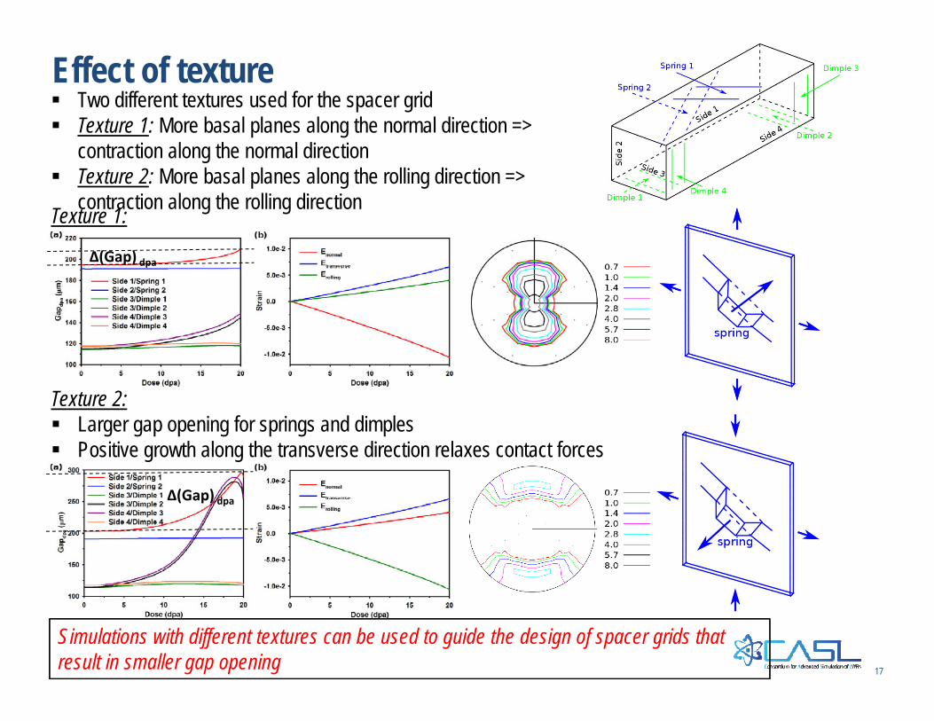
Effect of texture Two different textures used for the spacer grid Texture 1: More basal planes along the normal direction =>
contraction along the normal direction Texture 2: More basal planes along the rolling direction =>
contraction along the rolling direction
Texture 2: Larger gap opening for springs and dimples Positive growth along the transverse direction relaxes contact forces
Texture 1:
Simulations with different textures can be used to guide the design of spacer grids that result in smaller gap opening
Δ(Gap) dpa
Δ(Gap) dpa

18
GTRF plans to closeout