case study of 767 horizontal stabilizer - mit opencourseware · pdf filecase study of 767...
TRANSCRIPT
Case Study of 767 Horizontal Stabilizer
• Goals of this class – Carry through the topics of this course on one product
• Look in detail at a real aircraft structural assembly • Define and flow down KCs • Compare different assembly methods
– conventional one based on fixtures – proposed one based on part-to-part mating features
• Draw datum flow chains for them • Study the economics
767 Case Study 11/30/2004 © Daniel E Whitney 1
History of 767 Horizontal Stabilizer Project
• Fast/Flexible Manufacturing Project 1996 • Coordinated Aircraft and Auto industry projects• Vought Aircraft partner via LAI • Vought’s goal: cut costs, earn more Boeing
business • Vought’s hypothesis: convert from fixed to
flexible assembly tooling • Vought’s focus of project: 767 H. S. upper wing
subassembly 767 Case Study 11/30/2004 © Daniel E Whitney 2
Our Challenge: How To Do This
• Available data – Existing tooling – No history, people, drawings – Evidence of errors in tooling
• Our process – Understand goals of existing process – Reverse engineer from the top down – Expand scope of study to complete horizontal stabilizer – Look up the supply chain to Boeing to get the
requirements– Generate new process to achieve agreed goals
767 Case Study 11/30/2004 © Daniel E Whitney 3
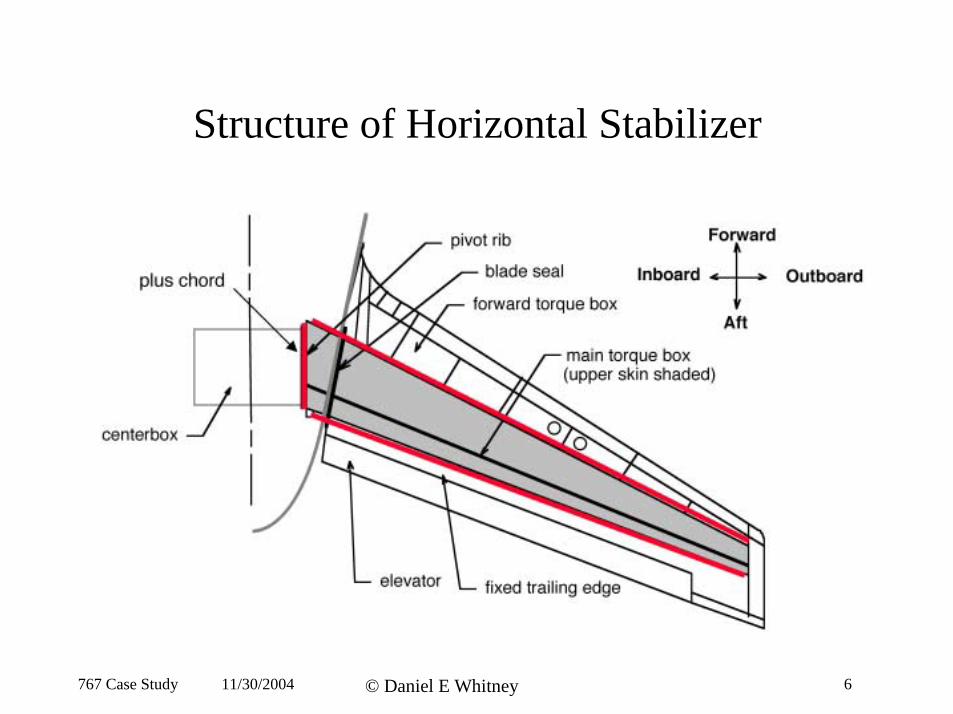
Structure of Horizontal Stabilizer
767 Case Study 11/30/2004 © Daniel E Whitney 6
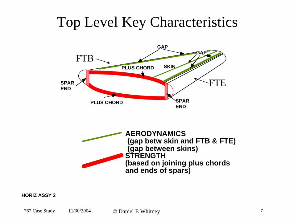
Top Level Key Characteristics
PLUS CHORD
PLUS CHORD SPAR
SPAR END
SKIN
GAP GAP
FTE
FTB
END
AERODYNAMICS (gap betw skin and FTB & FTE)(gap between skins)
STRENGTH (based on joining plus chordsand ends of spars)
HORIZ ASSY 2
767 Case Study 11/30/2004 © Daniel E Whitney 7
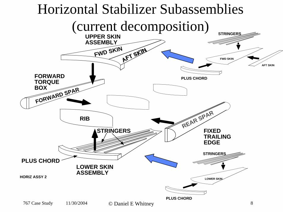
Horizontal Stabilizer Subassemblies (current decomposition)
UPPER SKIN ASSEMBLY
LOWER SKIN ASSEMBLY
RIB
FORWARD TORQUEBOX
FORWARD SPAR
FIXED TRAILING EDGE
STRINGERS
PLUS CHORD
REAR SPAR
FWD SKIN
HORIZ ASSY 2
STRINGERS
LOWER SKIN
STRINGERS
PLUS CHORD
FWD SKIN
AFT SKIN
PLUS CHORD 767 Case Study 11/30/2004 © Daniel E Whitney 8
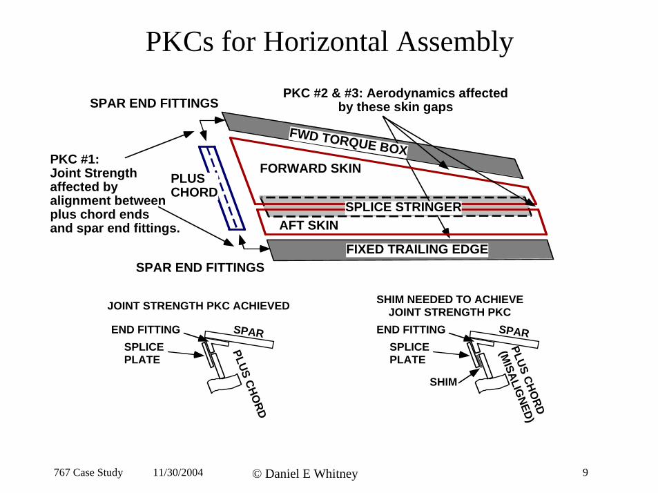
PKCs for Horizontal Assembly
PKC #2 & #3: Aerodynamics affectedby these skin gaps
PLUS CHORD
PKC #1: Joint Strengthaffected byalignment betweenplus chord endsand spar end fittings.
FWD TORQUE BOX
FIXED TRAILING EDGE
FORWARD SKIN
AFT SKIN
SPAR END FITTINGS
SPAR END FITTINGS
SPLICE STRINGER
JOINT STRENGTH PKC ACHIEVED SHIM NEEDED TO ACHIEVE JOINT STRENGTH PKC
SPAR
PLUSCHO
END FITTING
PLUSCHO
(MISALIG
SPAREND FITTING
SHIM
SPLICE SPLICE PLATE PLATE
N RRD
E DD )
767 Case Study 11/30/2004 © Daniel E Whitney 9
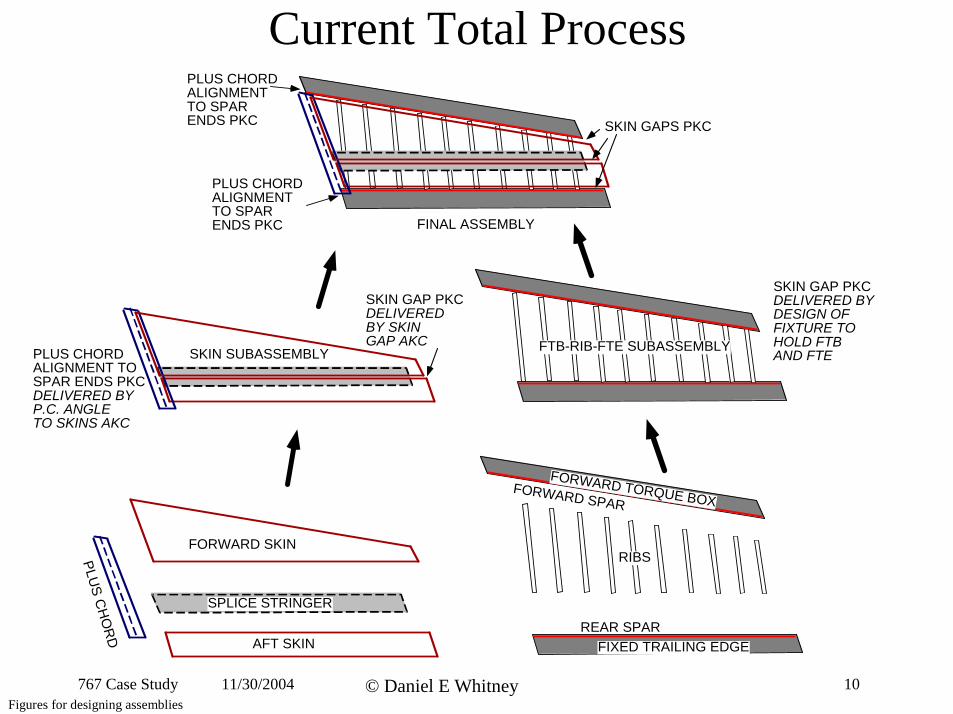
Current Total Process
SKIN GAP PKC DELIVERED BY DESIGN OF FIXTURE TO HOLD FTB AND FTESKIN SUBASSEMBLY
SKIN GAP PKC DELIVERED BY SKIN GAP AKC
PLUS CHORD ALIGNMENT TO SPAR ENDS PKC DELIVERED BY P.C. ANGLE TO SKINS AKC
FINAL ASSEMBLY
PLUS CHORD ALIGNMENT TO SPAR ENDS PKC SKIN GAPS PKC
PLUS
CH
OR
D AFT SKIN
FORWARD SKIN
SPLICE STRINGER
FIXED TRAILING EDGE
FORWARD TORQUE BOX
REAR SPAR
FORWARD SPAR
FTB-RIB-FTE SUBASSEMBLY
RIBS
PLUS CHORD ALIGNMENT TO SPAR ENDS PKC
767 Case Study 11/30/2004 © Daniel E Whitney Figures for designing assemblies
10
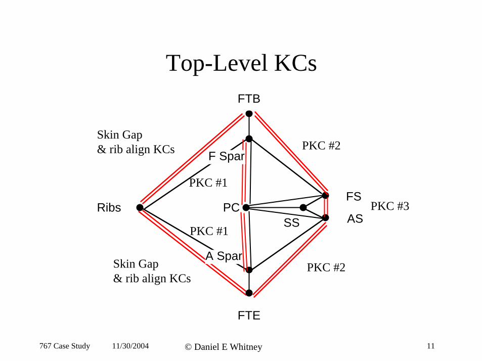
Top-Level KCsFTB
Ribs SS
PC
F Spar
A Spar
PKC #2
PKC #2
PKC #1
PKC #1
Skin Gap & rib align KCs
Skin Gap & rib align KCs
FS PKC #3
AS
FTE
767 Case Study 11/30/2004 © Daniel E Whitney 11
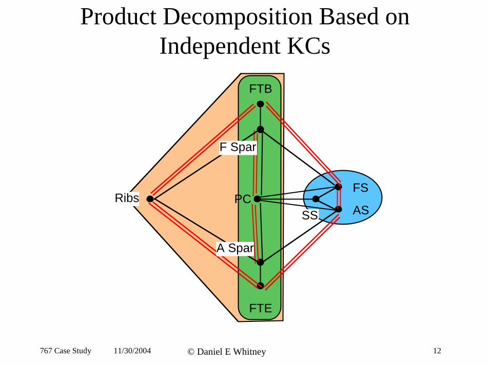
Product Decomposition Based on Independent KCs
FTB
FTE
Ribs PC SS
FS
AS
F Spar
A Spar
767 Case Study 11/30/2004 © Daniel E Whitney 12
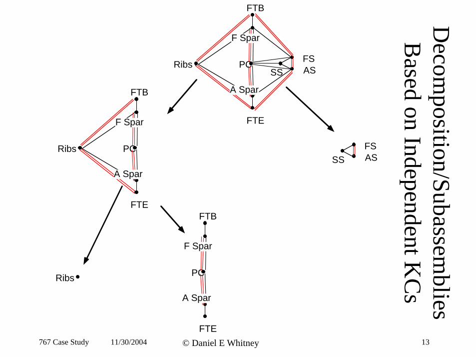
FTB
Ribs SS
FS AS
FTE
PC
F Spar
A Spar
SS Ribs PC
F Spar
A Spar
FTB
FTE
PC
F Spar
A Spar
FTB
Ribs
FSAS
Decom
position/Subassemblies
Based on Independent K
Cs
FTE 767 Case Study 11/30/2004 © Daniel E Whitney 13

Sob
767 Case Study 11/30/2004 © Daniel E Whitney 14
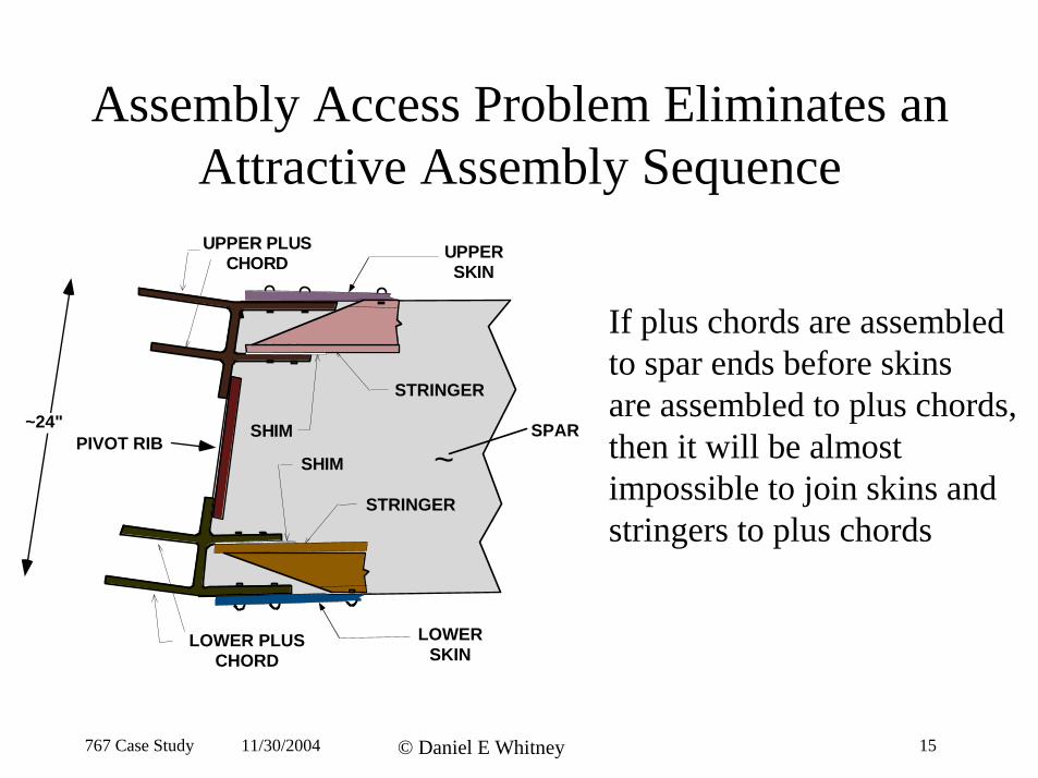
Assembly Access Problem Eliminates an Attractive Assembly SequenceUPPER PLUS
STRINGER
PIVOT RIB ~ ~24"
LOWER PLUS LOWER
STRINGER
UPPER SKIN
SHIM
CHORD
SHIM
If plus chords are assembled to spar ends before skins are assembled to plus chords,
SPAR then it will be almost impossible to join skins and stringers to plus chords
CHORD SKIN
767 Case Study 11/30/2004 © Daniel E Whitney 15
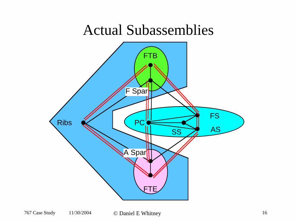
Actual Subassemblies
Ribs SS
FS
AS
FTB
FTE
PC
F Spar
A Spar
767 Case Study 11/30/2004 © Daniel E Whitney 16
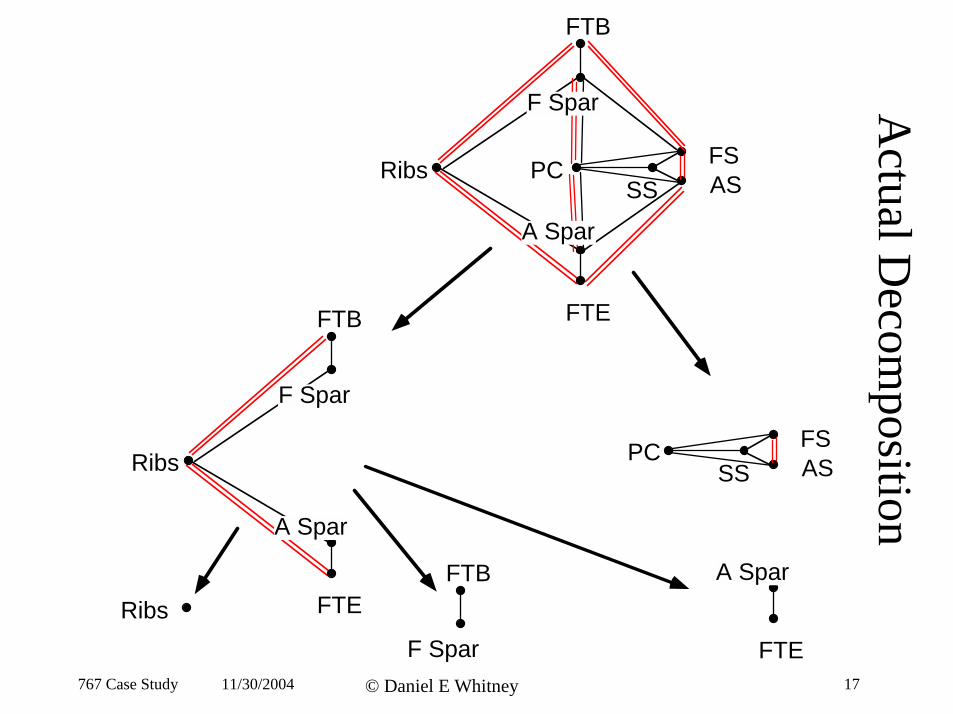
FTB
Actual D
ecomposition
Ribs SS
FS ASPC
F Spar
FTE
A Spar
SS FS AS
PC
FTB A Spar
Ribs
FTB
F Spar
FTE
A Spar
Ribs F Spar FTE
767 Case Study 11/30/2004 © Daniel E Whitney 17
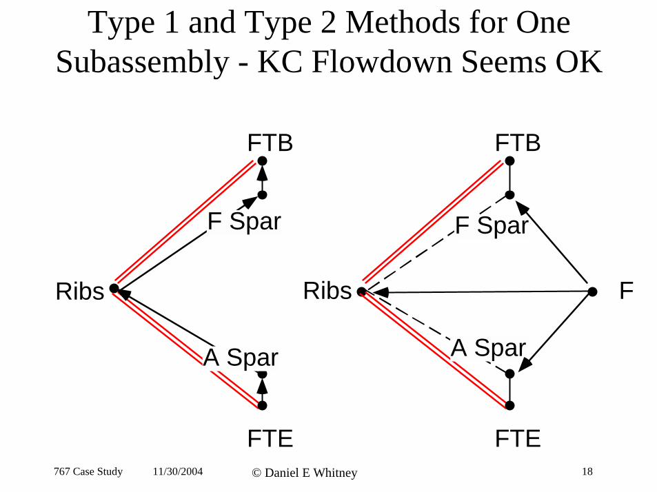
Type 1 and Type 2 Methods for One Subassembly - KC Flowdown Seems OK
FTB FTB
Ribs
F Spar
A Spar
Ribs
F Spar
A Spar
F
FTE FTE 767 Case Study 11/30/2004 © Daniel E Whitney 18
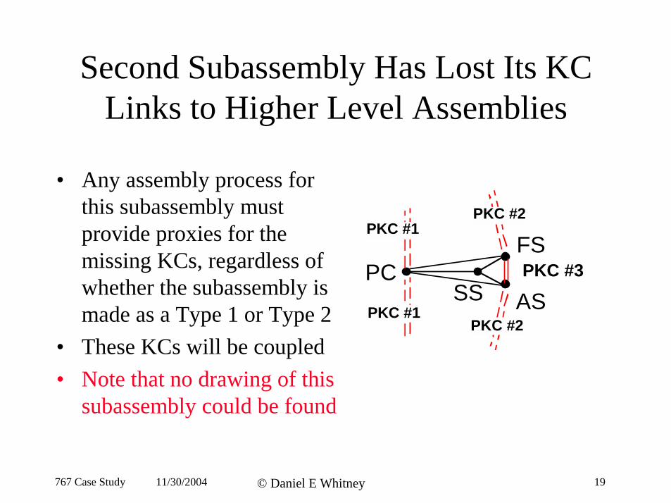
Second Subassembly Has Lost Its KC Links to Higher Level Assemblies
• Any assembly process for this subassembly must provide proxies for the
SSPC
PKC #1
PKC #1 PKC #2
PKC #2
FSmissing KCs, regardless of PKC #3 whether the subassembly is ASmade as a Type 1 or Type 2
• These KCs will be coupled • Note that no drawing of this
subassembly could be found
767 Case Study 11/30/2004 © Daniel E Whitney 19
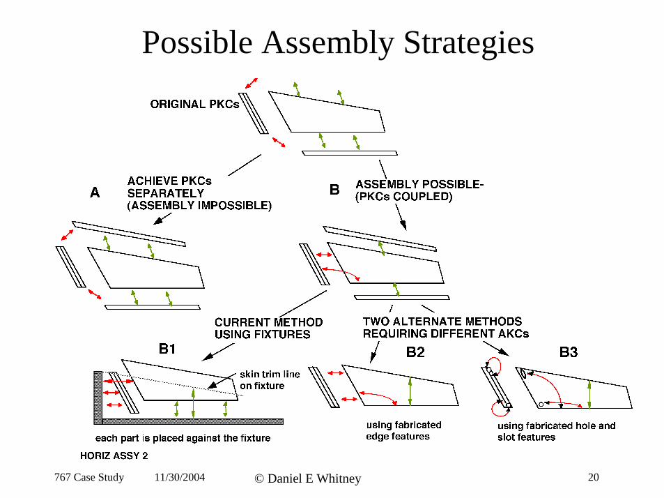
Possible Assembly Strategies
767 Case Study 11/30/2004 © Daniel E Whitney 20
Our Challenge
• Current assembly method relies on costly fixtures• Can a process be devised that does not rely on
fixtures other than for support against gravity? • Can such a process achieve the PKCs? • Would it be economical? • What new worker skills would be needed?• Can we figure out what the old process was doing
so we can reproduce its objectives using new methods?
767 Case Study 11/30/2004 © Daniel E Whitney 23
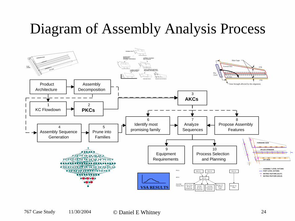
Diagram of Assembly Analysis Process
Product Architecture
Assembly Sequence Generation
4
PKCs 2
AKCs 3
Prune into Families
5 Analyze
Sequences
7
Assembly Decomposition
KC Flowdown 1
Identify most promising family
6
Process Selection and Planning
10 Equipment
Requirements
9
Propose Assembly Features
8
Skin Gaps
Joint Strength affected by this alignment.
FTB
FTE
Forward Skin
Aft Skin
Plus Chord
ORIGINAL PKCs
ACHIEVE PKCs SEPARATELY (ASSEMBLY IMPOSSIBLE)
ASSEMBLY POSSIBLE-PKCs COUPLED
CURRENT METHOD USING FIXTURES
TWO ALTERNATE METHODS REQUIRING DIFFERENT AKCs
using hole and slot featuresusing edge features
1 2
1 2
ASSEMBLY LEVEL DATUMS PART LEVEL DATUMS
FORWARD SKIN
AFT SKIN
SPLICE STRINGER
MATING FEATURE (SLOT) MATING FEATURE (HOLE)
PKC #1 PKC #2 PKC #3
AKC #1
PKCs
AKCs
Assembly Feature AKCs Plus Chord
aft hole & forward slot
Aft Skin aft hole &
inboard slot
Fwd Skin inboard slot & fwd slot
Stringer #3 inboard
holes
Stringer #3 holes
AFT SKINSTRINGER #3
FORWARD SKIN
STRINGER
PLUS CHORD
VSA RESULTS
767 Case Study 11/30/2004 © Daniel E Whitney 24
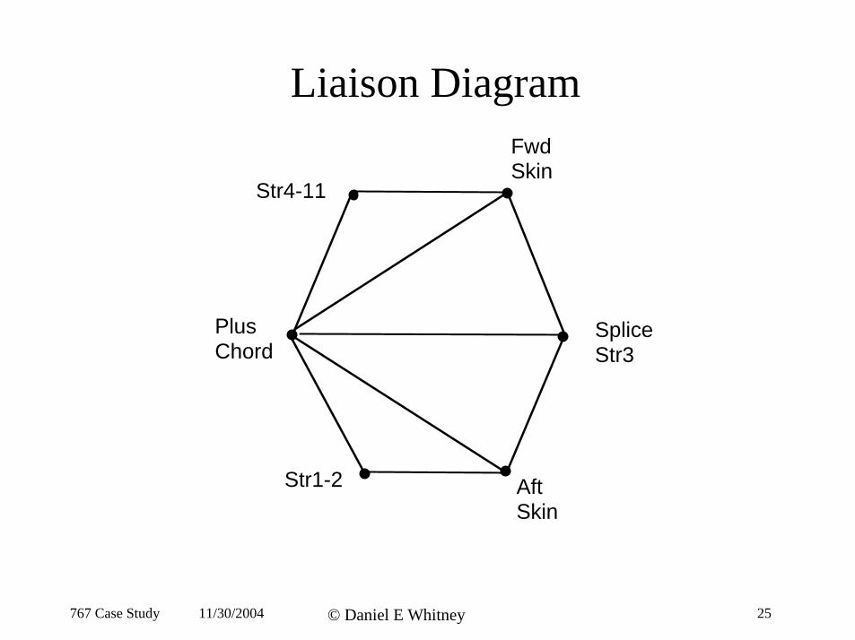
Liaison DiagramFwdSkin
Str4-11
Plus
Str1-2
SpliceChord Str3
Aft Skin
767 Case Study 11/30/2004 © Daniel E Whitney 25

Current Skin Assembly Process
PLUS CHORD FWD SKIN
AFT SKIN
SPLICE STRINGER
FIXTURE Everything indexes off the fixture
767 Case Study 11/30/2004 © Daniel E Whitney 26
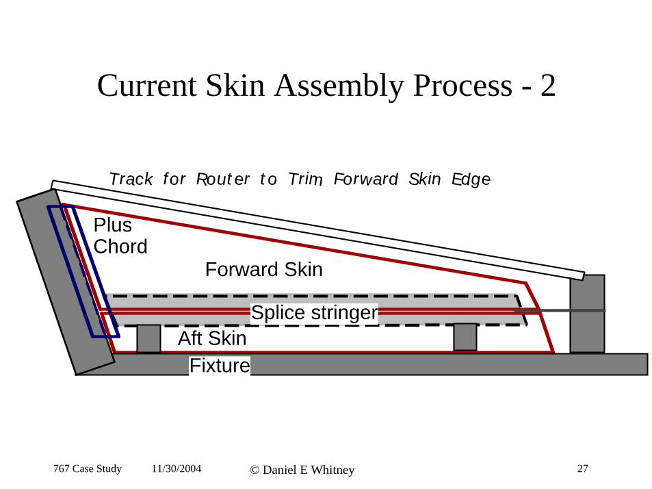
Current Skin Assembly Process - 2
Forward Skin
Aft Skin
Plus Chord
Splice stringer
Fixture
i iTrack for Rout er t o Tr m Forward Sk n Edge
767 Case Study 11/30/2004 © Daniel E Whitney 27
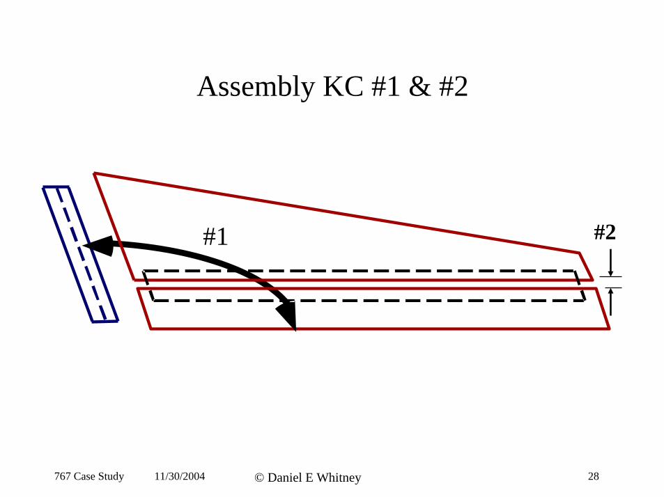
Assembly KC #1 & #2
#1 #2
767 Case Study 11/30/2004 © Daniel E Whitney 28
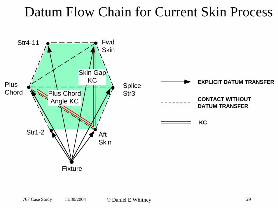
Datum Flow Chain for Current Skin Process
Str4-11
Aft Skin
Str1-2
Fwd Skin
Plus Chord Angle KC
Skin Gap KC EXPLICIT DATUM TRANSFER Plus Splice
Chord Str3 CONTACT WITHOUT DATUM TRANSFER
KC
Fixture
767 Case Study 11/30/2004 © Daniel E Whitney 29
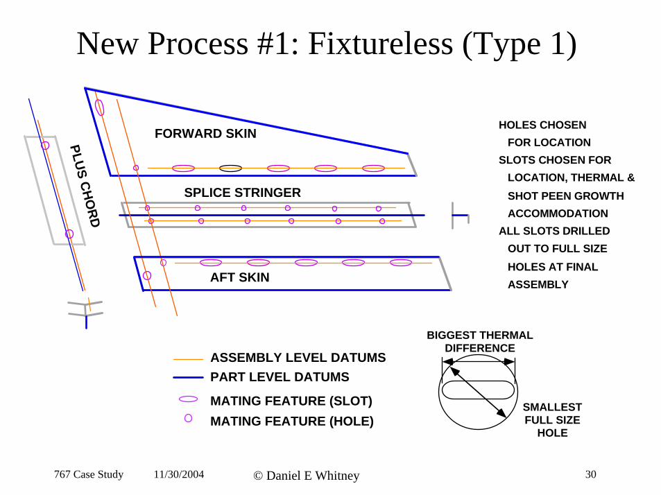
New Process #1: Fixtureless (Type 1)
FORWARD SKIN
AFT SKIN
SPLICE STRINGER
PLUS
CH
OR
D
HOLES CHOSEN FOR LOCATION SLOTS CHOSEN FOR LOCATION, THERMAL & SHOT PEEN GROWTH ACCOMMODATION ALL SLOTS DRILLED OUT TO FULL SIZE HOLES AT FINAL ASSEMBLY
BIGGEST THERMAL DIFFERENCE
ASSEMBLY LEVEL DATUMS PART LEVEL DATUMS
MATING FEATURE (SLOT) SMALLEST MATING FEATURE (HOLE) FULL SIZE
HOLE
767 Case Study 11/30/2004 © Daniel E Whitney 30
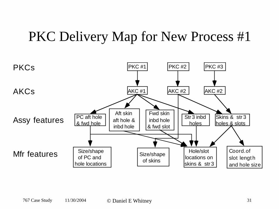
PKC Delivery Map for New Process #1
PKCs
AKCs
Assy features inbd hol
le in
aft holle
i le lot
il
PKC #1 PKC #2 PKC #3
AKC #1
Str 3 es
PC aft ho& fwd hole
AKC #2 AKC #2
Aft ske &
inbd ho
Fwd skin nbd ho
& fwd s
Sk ns & str 3 holes & s ots
Size/shape Hole/slot Coord.of Mfr features of PC and Size/shape locations on slot lengt h of skins hole locations skins & str 3 and hole size
767 Case Study 11/30/2004 © Daniel E Whitney 31
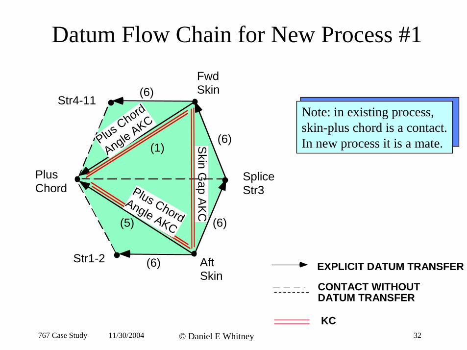
Datum Flow Chain for New Process #1
Fwd Skin
Skin G
ap AK
C
Plus Chord
Angle AKC
Plus ChordAngle AKC
AftStr1-2
Str4-11 (6)
(6)
(6)
(6)(1)
(5)
Note: in existing process, skin-plus chord is a contact. In new process it is a mate.
Splice Str3
EXPLICIT DATUM TRANSFER
PlusChord
Skin CONTACT WITHOUT DATUM TRANSFER
KC 767 Case Study 11/30/2004 © Daniel E Whitney 32
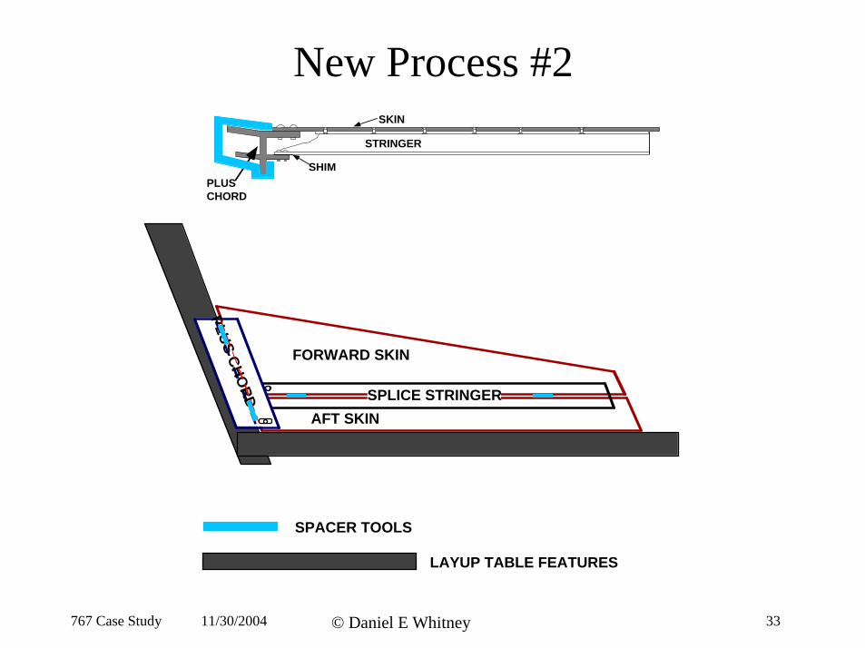
New Process #2
PLUS
STRINGER
SKIN
SHIM
CHORD
FORWARD SKIN
AFT SKIN SPLICE STRINGER
PLUSCHO
RD
SPACER TOOLS
LAYUP TABLE FEATURES
767 Case Study 11/30/2004 © Daniel E Whitney 33
.
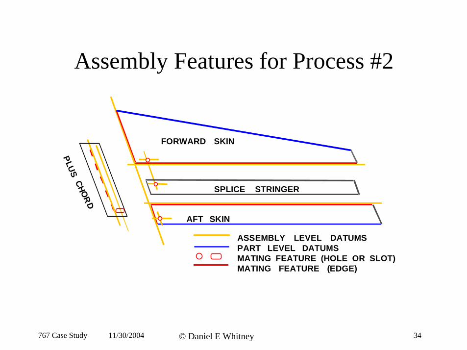
Assembly Features for Process #2
SCHOR
D
AFT
(
SKIN
ASSEMBLY LEVEL DATUMS PART LEVEL DATUMS MATING FEATURE HOLE OR SLOT)
FORWARD SKIN
SPLICE STRINGER
P L
U
MATING FEATURE (EDGE)
767 Case Study 11/30/2004 © Daniel E Whitney 34
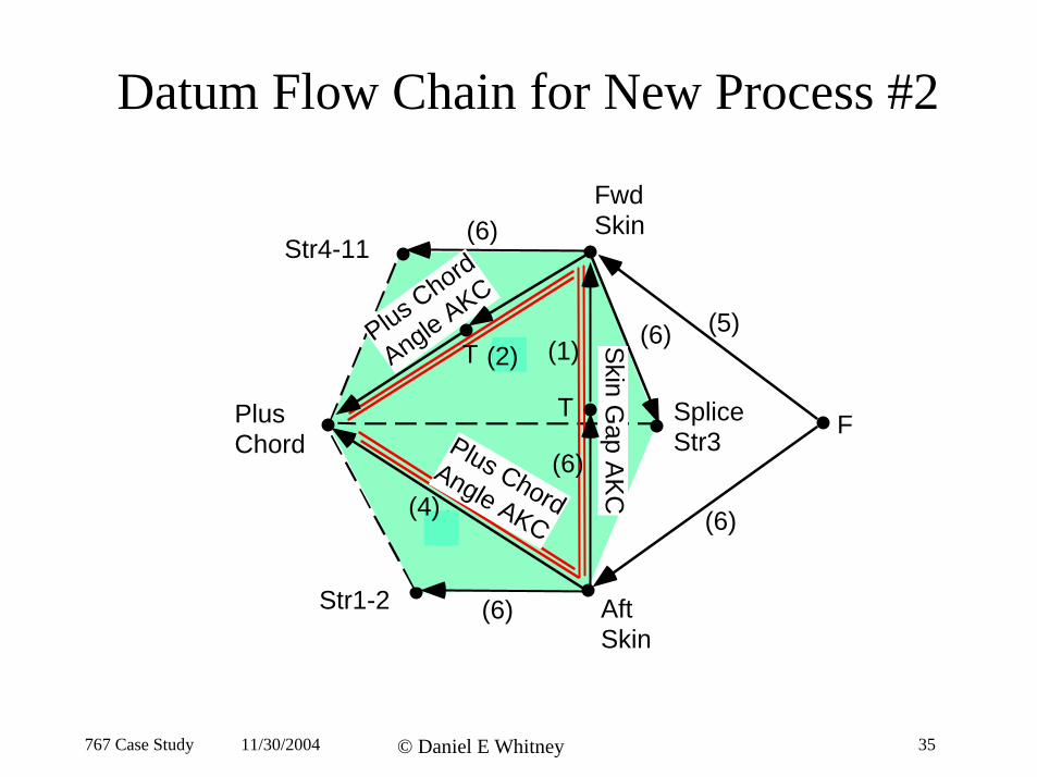
Datum Flow Chain for New Process #2
Fwd
Plus Chord
Angle AKC
Plus ChordAngle AKC
Splice Str3
AftStr1-2
Str4-11 (6)
(6)
(6)
(6)(1)
(5)
T
T S
kin Gap A
KC
(5)
(6)
(1)(2)
(4)
Skin
Plus FChord
Skin
767 Case Study 11/30/2004 © Daniel E Whitney 35
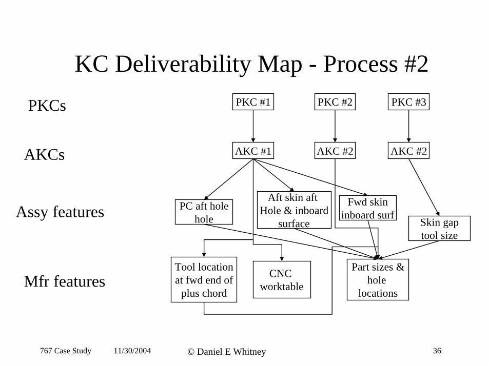
KC Deliverability Map - Process #2
PKCs
AKCs
Assy features
Mfr features
PKC #1 PKC #2 PKC #3
AKC #1
Fwd skinPC aft hole hole
AKC #2 AKC #2
at fwd end of
Aft skin aft
Skin gap tool size
CNC worktable hole
inboard surf
Tool location
plus chord
Hole & inboard surface
Part sizes &
locations
767 Case Study 11/30/2004 © Daniel E Whitney 36
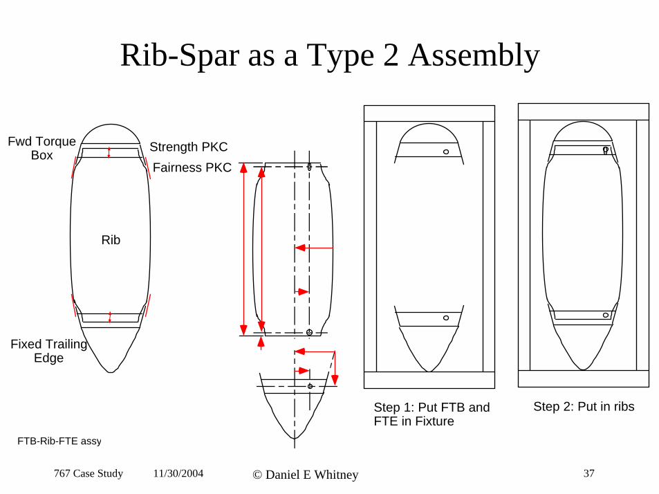
Rib-Spar as a Type 2 Assembly
Fairness PKC Strength PKCFwd Torque
Box
Fixed TrailingEdge
Rib
Step 1: Put FTB andFTE in Fixture
Step 2: Put in ribs
FTB-Rib-FTE assy
767 Case Study 11/30/2004 © Daniel E Whitney 37
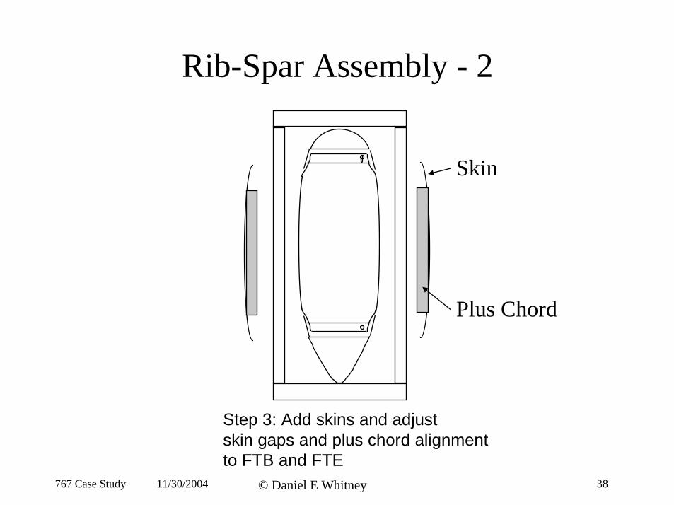
Rib-Spar Assembly - 2
Skin
Plus Chord
Step 3: Add skins and adjust skin gaps and plus chord alignment to FTB and FTE
767 Case Study 11/30/2004 © Daniel E Whitney 38
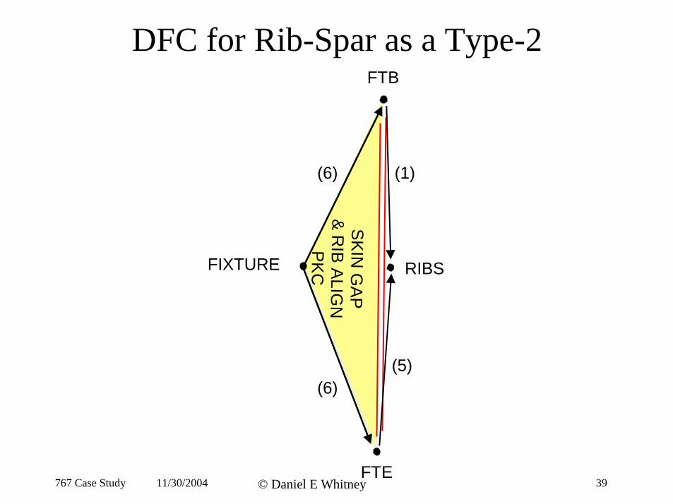
DFC for Rib-Spar as a Type-2FTB
FIXTURE RIBS
(1)
(5)
SK
IN G
AP
&
RIB
ALIG
N
PK
C
(6)
(6)
FTE 767 Case Study 11/30/2004 © Daniel E Whitney 39
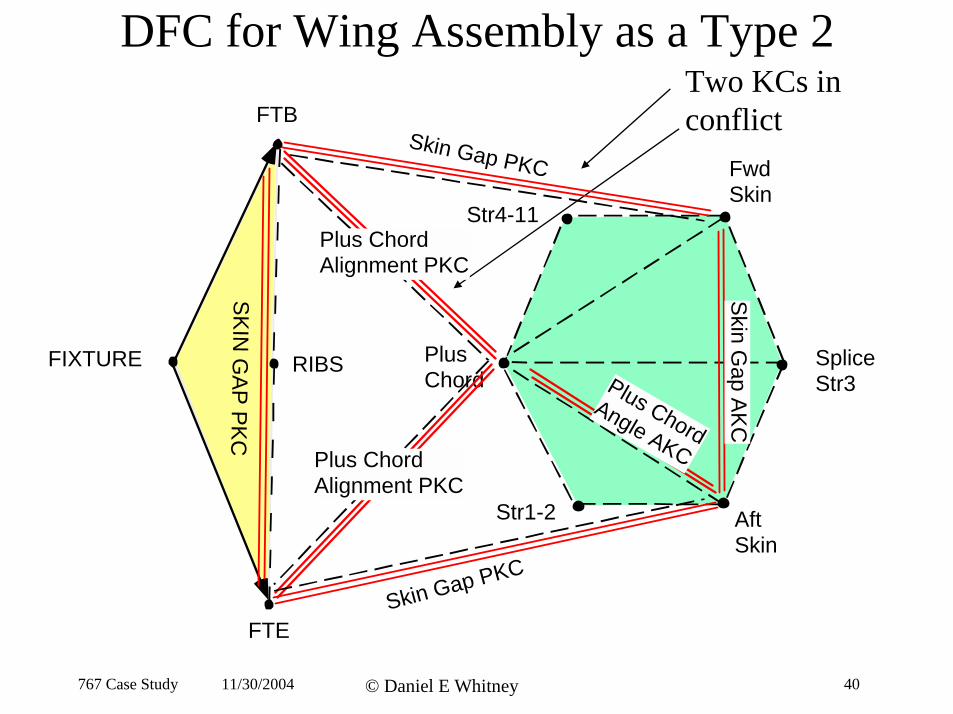
DFC for Wing Assembly as a Type 2
conflict
Aft Skin
Str1-2
Plus Chord
Str4-11
Fwd Skin
Plus ChordAngle AKC
Skin G
ap AK
C
SK
IN G
AP
PK
C
FTB
RIBS
Skin Gap PKC
Skin Gap PKC
Plus Chord Alignment PKC
Plus Chord Alignment PKC
Two KCs in
FIXTURE Splice Str3
FTE
767 Case Study 11/30/2004 © Daniel E Whitney 40
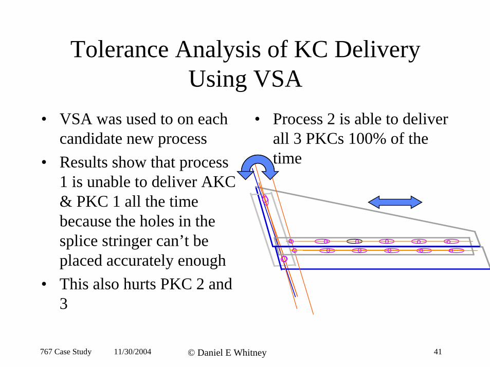
Tolerance Analysis of KC Delivery Using VSA
• VSA was used to on each • Process 2 is able to deliver candidate new process all 3 PKCs 100% of the
• Results show that process 1 is unable to deliver AKC & PKC 1 all the time because the holes in the splice stringer can’t be placed accurately enough
• This also hurts PKC 2 and
time
767 Case Study 11/30/2004 © Daniel E Whitney 41
3
)Matlab(TM Analysis
• Assumed assemblers could maneuver the wing skin laterally and angularly
• Assumed smaller variation in hole and slot placement
• Assumed that the rest of the wing was error-free
• Determined that only a few assemblies would fail
767 Case Study 11/30/2004 © Daniel E Whitney 42
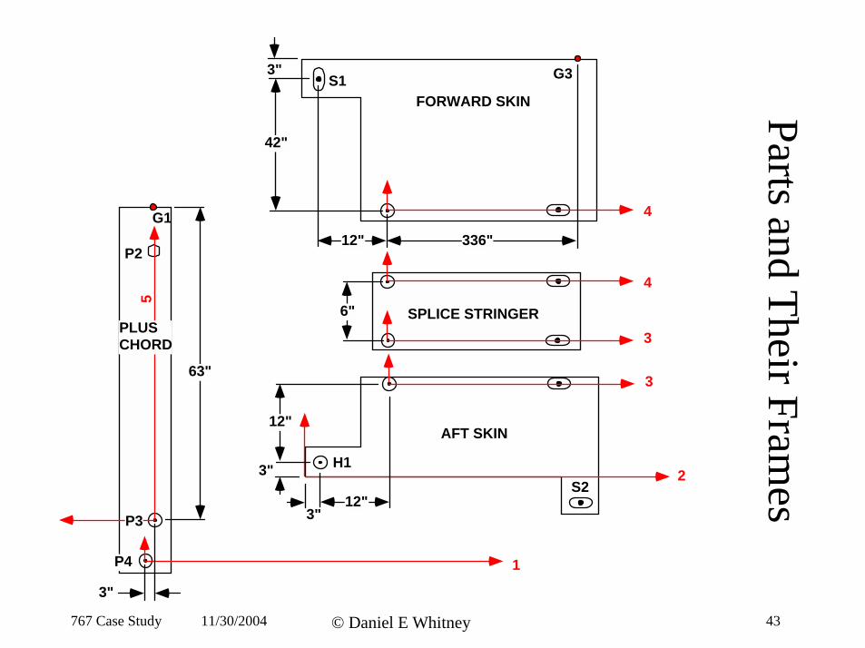
AFT SKIN
H1 S2
3
12"
3"
3" 12"
SPLICE STRINGER 3
4
6"
FORWARD SKIN
G3S1
4
42"
3"
12" 336" G1
P2
P4
5
P3
1
63"
PLUS CHORD
3"
2
Parts and Their Frames
767 Case Study 11/30/2004 © Daniel E Whitney 43
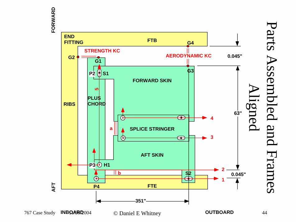
Parts Assem
bled and Frames
Aligned
FTE
RIBS
FTB
PLUS CHORD
FORWARD SKIN
SPLICE STRINGER
AFT SKIN
G1G2
G3
G4
S1P2
H1 S2
P4 1
2
3
4
5
a
b
STRENGTH KC
P3
63"
0.045"
0.045"AERODYNAMIC KC
351"
END FITTING
FOR
WA
RD
AFT
767 Case Study INBOARD11/30/2004 © Daniel E Whitney OUTBOARD 44
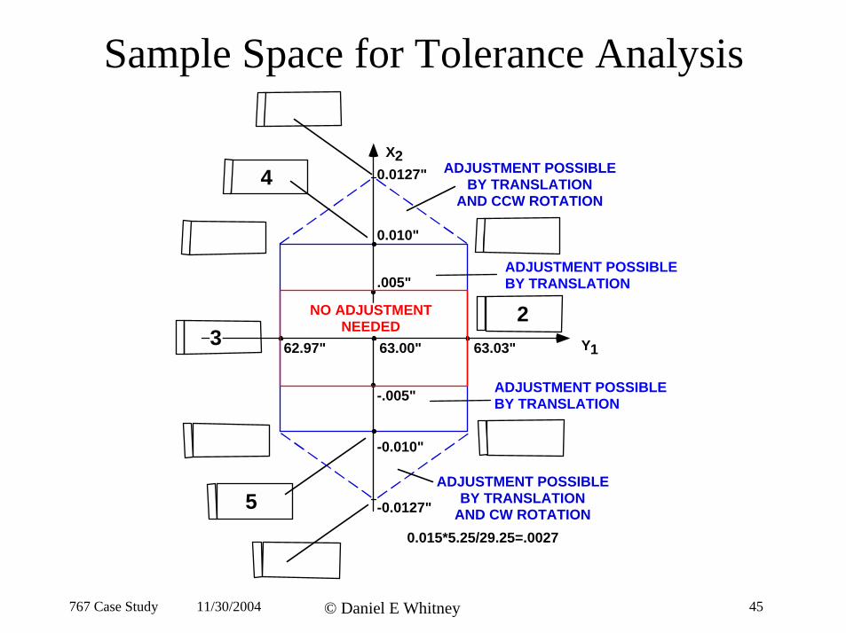
Sample Space for Tolerance Analysis
Y1
X2
0.010"
-0.010"
63.03"63.00"62.97"
0.0127"
-0.0127"
NO ADJUSTMENT NEEDED
ADJUSTMENT POSSIBLE BY TRANSLATION
AND CW ROTATION
ADJUSTMENT POSSIBLE BY TRANSLATION
AND CCW ROTATION
.005"
-.005"
0.015*5.25/29.25=.0027
2 3
4
5
ADJUSTMENT POSSIBLE BY TRANSLATION
ADJUSTMENT POSSIBLE BY TRANSLATION
767 Case Study 11/30/2004 © Daniel E Whitney 45
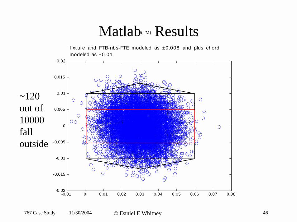
767 Case Study 46© Daniel E Whitney11/30/2004
Matlab(TM) Results
-0.01 0 0.01 0.02 0.03 0.04 0.05 0.06 0.07 0.08-0.02
-0.015
-0.01
-0.005
0
0.005
0.01
0.015
0.02
f ixt ure and FTB-ribs-FTE modeled as ±0.008 and plus chordmodeled as ±0.01
~120out of10000falloutside

Pros & Cons of Proposed Processes
Current Process Proposed Process #1 Proposed Process #2 Pros • Delivers all AKCs • Delivers AKC #2 • Delivers all AKCs
and PKCs and PKC #3 and PKCs repeatably repeatably
• Completely flexible method
repeatably • Completely flexible
method • No dedicated
fixtures • Uses existing fab
equipment • Least costly
• Uses existing fab equipment
• Controls critical interfaces
• Controls critical interfaces
Cons • Inflexible fixtures • Fails to deliver • Requires higher• Variation absorbed AKC #1 on a few functionality tack
at stringer-plus chord interface
assemblies • PKC #1 & #2 not
fixture (higher cost)
delivered • Requires a limited on those same number of small assembies fixtures
767 Case Study 11/30/2004 © Daniel E Whitney 47
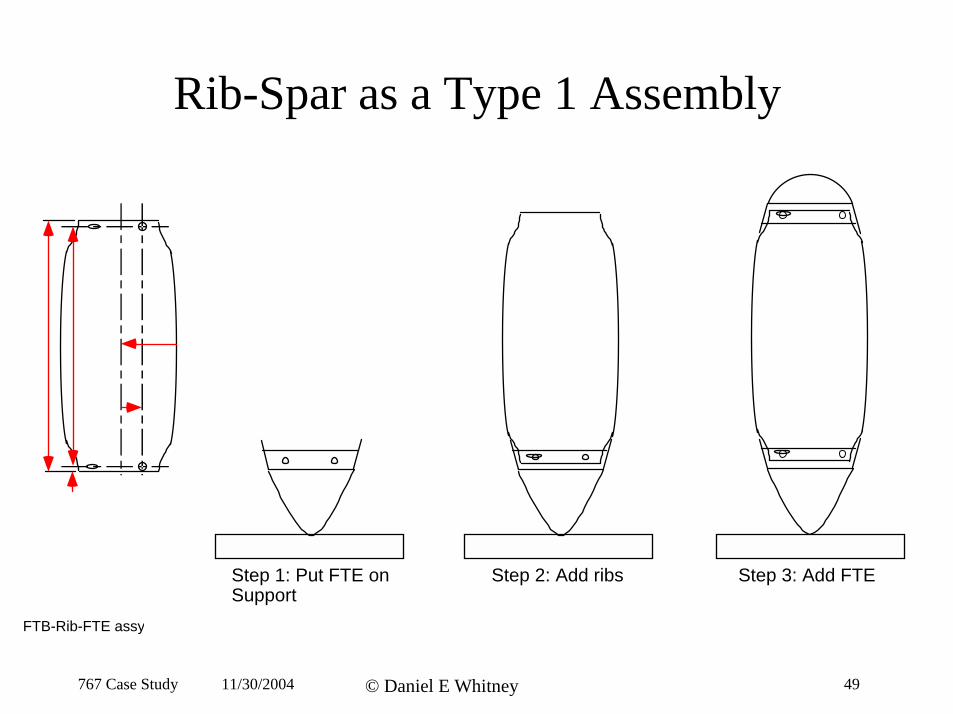
Rib-Spar as a Type 1 Assembly
Step 1: Put FTE onSupport
Step 2: Add ribs Step 3: Add FTE
FTB-Rib-FTE assy
767 Case Study 11/30/2004 © Daniel E Whitney 49
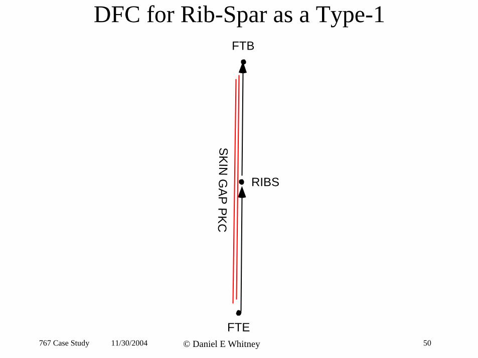
DFC for Rib-Spar as a Type-1FTB
RIBS
N G
AP
PK
C
IS
K
FTE 767 Case Study 11/30/2004 © Daniel E Whitney 50
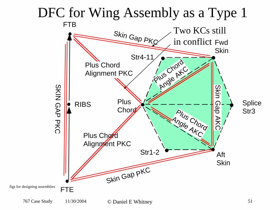
DFC for Wing Assembly as a Type 1FTB
in conflict
Aft Skin
Str1-2
Plus Chord
Str4-11
Fwd Skin
Plus Chord Alignment PKC
Plus Chord Alignment PKC
RIBS
Two KCs still Skin Gap PKC
dorh Cs C Ke AuP l glnA
S
Skin G
ap AK
C
KIN
SpliceStr3
G
P
A
lus Chor
P Ang
P
le AKCd
KC
Skin Gap PKC
figs for designing assemblies FTE 767 Case Study 11/30/2004 © Daniel E Whitney 51
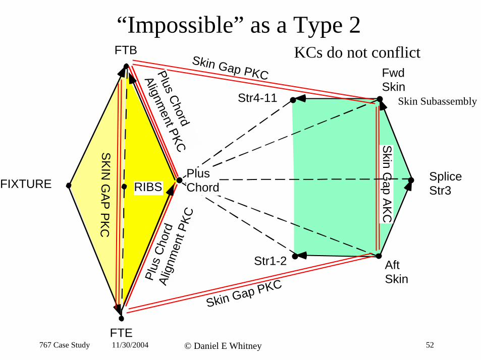
“Impossible” as a Type 2FTB KCs do not conflict
FIXTURE
Aft Skin
Str1-2
Str4-11
Fwd Skin
Skin G
ap AK
C
Skin Gap PKC
Skin Gap PKC
SK
IN G
AP
PK
C
RIBS
Plus
Cho
rd
Alig
nmen
t PKC
PlusChord
Alignment PKC
Plus Chord
Skin Subassembly
Splice Str3
FTE 767 Case Study 11/30/2004 © Daniel E Whitney 52
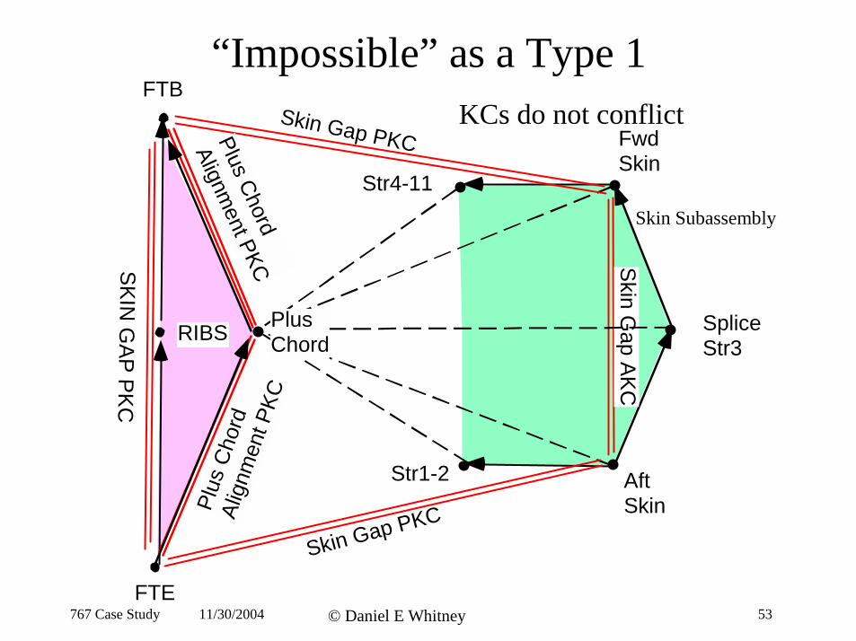
“Impossible” as a Type 1FTB
Skin G
ap AK
C
Skin Gap PKC
Skin Gap PKC
Plus
Cho
rd
Alig
nmen
t PKC
PlusChord
Alignment PKC
KCs do not conflict Fwd Skin
Str4-11 Skin Subassembly
SK
N G
AP
PK
C
I
Plus Splice Str3
RIBS Chord
Str1-2 Aft Skin
FTE 767 Case Study 11/30/2004 © Daniel E Whitney 53
Cost Analysis -1
• The basis for analysis was the KC-driven Precision Assembly (PA) process for the 767 horizontal upper skin assy.
• PA time and cost were estimated for the 767 skin
• The 767 cost/time analysis was scaled for the remaining 747 & 767 assemblies Vought makes for Boeing.
• PA assumed to be accomplished in three distinct cells: Tack, CNC Auto-Rivet, Final Assembly
• These cells all require new investment 767 Case Study 11/30/2004 © Daniel E Whitney 54
Cost Analysis - 2
• Baseline times for each step were taken from Vought’s estimates for its process.
• Required cell time for MIT’s processes was estimated based on Vought’s times and a distribution of realization factors applied to obtain an assembly time for each cell.
• A computer simulation was conducted to determine the necessary capital equipment.
767 Case Study 11/30/2004 © Daniel E Whitney 55
Simulation Scenarios
• Three PA processes were developed and analyzed.
• The 3 processes are “Vought,” “MIT 1,” and “MIT 2” • “Vought” is Vought’s proposed PA process • “MIT 1” uses holes and slots. It was derived from “Vought” by applying the KC flowdown
method. “MIT 2” uses NC tack cell
• Three scenarios were studied: - All Boeing assemblies, all programs - Four representative assemblies - Introduction of a new assembly - New assembly would require new fixed tool but not new PA equipment
• One and Two shift operations 767 Case Study 11/30/2004 © Daniel E Whitney 56
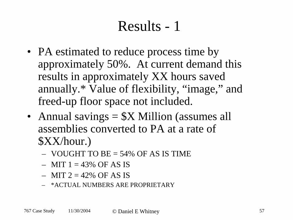
Results - 1
• PA estimated to reduce process time by approximately 50%. At current demand this results in approximately XX hours saved annually.* Value of flexibility, “image,” and freed-up floor space not included.
• Annual savings = $X Million (assumes all assemblies converted to PA at a rate of $XX/hour.) – VOUGHT TO BE = 54% OF AS IS TIME– MIT 1 = 43% OF AS IS – MIT 2 = 42% OF AS IS– *ACTUAL NUMBERS ARE PROPRIETARY
767 Case Study 11/30/2004 © Daniel E Whitney 57
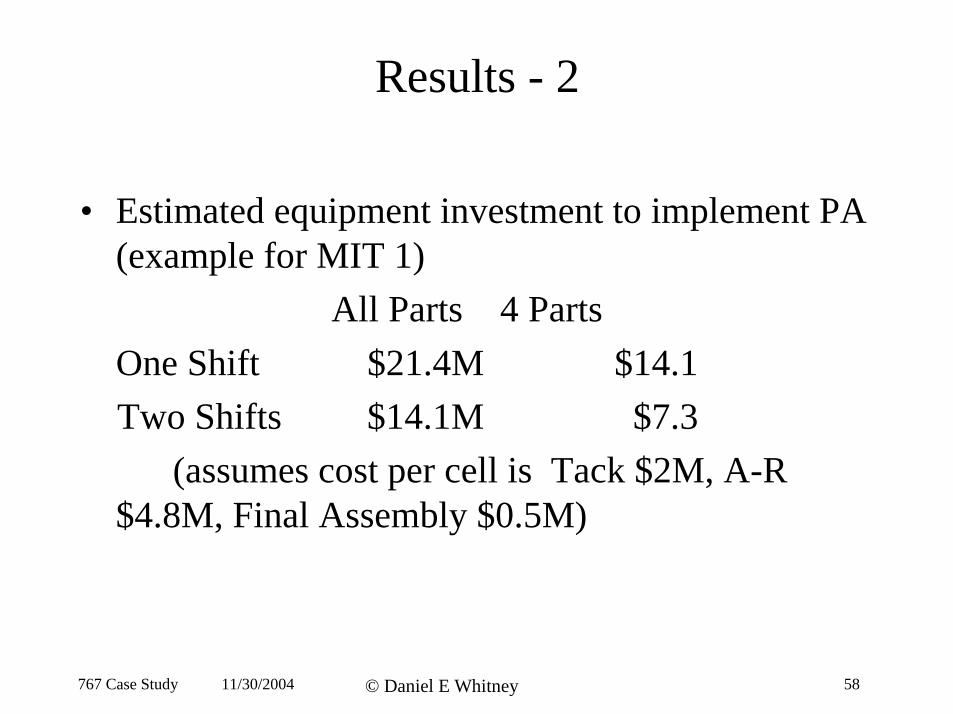
Results - 2
• Estimated equipment investment to implement PA (example for MIT 1)
All Parts 4 Parts One Shift $21.4M $14.1 Two Shifts $14.1M $7.3
(assumes cost per cell is Tack $2M, A-R $4.8M, Final Assembly $0.5M)
767 Case Study 11/30/2004 © Daniel E Whitney 58
Results - 3
• Current economics did not justify the new process• The new process becomes economical if Vought
gains new business for which it can use the new cells, thus saving the cost of new hard fixtures
• Training and cultural issues remain to be evaluated– Adjusting by hand becomes adjusting via computer– Ad hoc process becomes a preplanned and designed
one requiring more manufacturing knowledge during design
– More communication between fab and assembly shops needed
767 Case Study 11/30/2004 © Daniel E Whitney 59