carbon nanostructured materials from waste engine oil and its field electron emission properties
TRANSCRIPT

Department of Physics
FACULTY OF SCIENCE AND MATHEMATICS
UNIVERSITI PENDIDIKAN SULTAN IDRIS
CARBON NANOSTRUCTURED MATERIALS
FROM WASTE ENGINE OIL
AND ITS FIELD ELECTRON EMISSION PROPERTIES
Main Supervisor : Assoc. Prof. Dr. Suriani Abu Bakar
Co-Supervisors : Dr. Mohamad Hafiz Mamat (UiTM)
Prof. Dr. Abdul Rahman Mohamed (USM)
SUHUFA ALFARISA
M20131000689
MATERIAL PHYSICS
14th January, 2015

OUTLINES
1. OVERVIEW
2. RESEARCH BACKGROUND
3. RESEARCH PROBLEMS
4. RESEARCH OBJECTIVES
5. METHODOLOGY
6. RESULTS AND DISCUSSION
7. CONCLUSIONS AND FUTURE WORK
8. REFERENCES
9. ACKNOWLEDGEMENTS
2

1. OVERVIEW
WEO Ferrocene
catalyst
2-TCVD
carbon material on Si
substratesCS / CNTs
ZnO
MgZnOSi
substrate
CS / CNTs
Si
substrate
ZnO
MgZnO
Carbon/ZnO
composite structure
3

2. RESEARCH BACKGROUND
Nanotechnology :
Fabrications, characterizations,
and applications of a system,
Material or devices in the size
of nanoscale which is
1 to 100 nm.
Carbon materials
have wide range
applications due to
their unique properties;
conductive, strong, etc.
Conventional carbon
sources to produce
carbon materials are
expensive due to the
limited availability.
Several natural oils and
waste materials have
been introduced for the
production of carbon
materials.
12
3
High carbon content of
Waste engine oil (WEO)
made it suitable as precursor
for nanostructured carbon
production. WEO has been
used for the production of
carbon sphere (CS) using dry
autoclaving method.
4
Composite structure of
carbon material with
another nanostructured
can enhance the
performance of material.
5
CNTs/ZnO composite
has been reported gave a
better field emission
properties as compared
to CNTs or ZnO only.
6
4
Nanotechnology :
Fabrications, characterizations,
and applications of a system,
Material or devices in the size
of nanoscale which is
1 to 100 nm.
Carbon materials
have wide range
applications due to
their unique properties;
conductive, strong, etc.
12
High carbon content of
Waste engine oil (WEO)
made it suitable as precursor
for nanostructured carbon
production. WEO has been
used for the production of
carbon sphere (CS) using dry
autoclaving method.
4

2. RESEARCH BACKGROUND
Carbon can be formed into many kinds of nanostructured
diamond
amorphous carbon
(a-C) graphite
grapheneCarbon nanotubes
(CNTs)
spherical
carbon material
RESEARCH BACKGROUND – CARBON MATERIALS
Various nanostructured carbon (Scarselli, Castrucci, & Crescenzi, 2012; J. Wang, Hu,
Xu, & Zhao, 2014).
5

Carbon spheres (CS) spherical shape of carbon structure with severallayers.
CNTs made from a single or multi layers of graphene sheets which arerolled up into tubular shape.
The research on carbon materials is more intensively studied after thediscovery of spherical carbon namely fullerene by Kroto et al. (1985) and thereport on CNTs by Iijima (1991).
RESEARCH BACKGROUND – CARBON MATERIALS
Very strong, sharp, and
flexible thus the tip can
bent to touch the hilt
A research group from University of Dresden in 2006 revealed the existence of
CNTs in Damascus sword, which was used by Salahudin Al Ayubi and his army in
Crusades III (1192).
6

ENERGYHigh surface area
Catalysis support
Ion adsorption
Supercapacitor
Battery
ELECTRONICSHigh current density
High electron mobility
High thermal conductivity
Metallic/semiconductive
Transistor
Wiring
Conductive transparent thin film
Electron emitter
Sensor
MATERIALLight
High physical strength
High wear resistance
Reinforced resin/metal
Composite material
Filler
(sport equipment, tyre)
BIOTECHNOLOGY
Strong adsorption
High surface area
High affinity binding
Biosensor
Drug delivery system
CNTs
CS
RESEARCH BACKGROUND – CARBON MATERIALS 7

RESEARCH BACKGROUND – CHEMICAL VAPOUR DEPOSITION
SYNTHESIS METHOD
Chemical vapor deposition (CVD) for carbon materials production: chemical
process to produce carbon materials by the decomposition of carbon
precursor (gas, solid or liquid).
The presence of catalyst (seeded or floated catalyst).
Thermal CVD (TCVD) using thermal energy during the reaction process.
TCVD
1-stage
2-stage
simple preparation
easy controlled growth by changing thesynthesis parameter (temperature, carriergas flow, synthesis time, etc)
Good quality
Promising for large scale production
Cost effective
8

RESEARCH BACKGROUND – CARBON PRECURSORS
CARBON PRECURSORS
The use of conventional fossil fuel carbon source is notefficient and cost effective due to:
non-renewable propertieslimited availability
expensive
Natural precursors for carbon material production;
turpentine, eucalyptus, palm, corn, sesame, olive oil.
However, the use of these natural precursor is less effectivedue to its collision with food and health sector.
Waste materials were then used as alternative precursor;
waste cooking palm oil, chicken fat, waste plastic, banana peel, heavyoil residue, WEO.
9

RESEARCH BACKGROUND – WASTE CARBON PRECURSORS
No. Authors Precursors Methods Findings
1. Kukovitskii, et al. (1997)
Chem. Phys. Lett. 266(3-4),
323-328.
Waste plastic
(polyethylene)
Catalytic
pyrolisis
Carbon fiber
(CF), CNTs
2. Arnaiz et al. (2013)
Ind. Eng. Chem. Res.
52(42), 14847-14854.
Waste plastic
(polyethylene)
CVD CNTs
3. Oh et al. (2012)
Sci. Tech. Adv. Mater.
13(2), 025004.
Waste bottle
plastic
Microwave
irradiation
CNTs
4. Suriani, et al. (2010)
J. Ceram. Soc. Jpn.
118(1382), 963-968.
Waste cooking
palm oil
Thermal CVD
(TCVD)
CNTs
5. Suriani et al. (2013)
Mater. Lett. 101, 61-64.
Waste chicken fat Thermal CVD
(TCVD)
CNTs
Table 1. Production of carbon materials using waste precursors
10

RESEARCH BACKGROUND – WASTE CARBON PRECURSOR
No. Authors Precursors Methods Findings
6. Datta, Dutta et al. (2013)
J. Nanopart. Res. 15(7), 1-
15.
Waste natural oils
(mustard, soybean,
sesame and castor)
Dry
autoclaving
Carbon
nanowhiskers
7. Datta, Sadhu et al. (2013)
Corros. Sci. 73, 356–364.
Waste engine oil
(WEO)
Dry
autoclaving
CS
8. Li et al. (2012)
Chem. Eng. J. 211-212,
255-259.
Heavy oil residue CVD CNTs
9. Mopoung (2011)
Int. J. Phys.Sci. 6, 1789-
1792.
Banana peel Pyrolisis CNTs,
nanocarbon
10. Mohammed (2013)
Adv. Mater. Sci. Eng. 2013,
1-6.
Deoiled asphalt CVD CS
11

WASTE ENGINE OIL
RESEARCH BACKGROUND – WASTE ENGINE OIL
Scientific
• High carbon content/hydrocarbon chain
• 85.01 wt% (CHNS analysis)
• C10 to C27 (GC-MS analysis)
Scientific
• Contain heavy metal contaminant which can be used asadditional catalyst for the growth of carbon materials.
Economic
• Abundant waste
• Cheaper
• Available and easy collect in large volume
Environ-
ment
• Conventionally, WEO is converted into diesel fuel, re-refinedinto lubricating oil.
• Illegal disposal of WEO can harm and pollute environment
12

WASTE ENGINE OIL
RESEARCH BACKGROUND – WASTE ENGINE OIL
Scientific
• High carbon content/hydrocarbon chain
• 85.01 wt% (CHNS analysis)
• C10 to C27 (GC-MS analysis)
Scientific
• Contain metal contaminants which can be used as additionalcatalyst for the growth of carbon materials.
Economic
• Abundant waste
• Cheaper
• Available and easy collect in large volume
Environ-
ment
• Conventionally, WEO is converted into diesel fuel, re-refinedinto lubricating oil.
• Illegal disposal of WEO can harm and pollute environment
13

RESEARCH PROBLEMS
Expensive and limited conventional sources to produces carbon
material
Abundance
of WEO
NOVEL SOLUTION
WEO as carbon source toproduce carbon materials
Pollution caused by illegal disposal
of WEO
PRODUCTS
3. RESEARCH PROBLEMS
14

1. To produce carbon nanostructured materials from waste engine oil
using thermal chemical vapor deposition method at various synthesis
parameters.
3. To fabricate carbon/zinc oxide nanostructures composites.
4. To investigate field electron emission properties of carbon
nanostructured materials from waste engine oil and carbon/zinc oxide
nanostructures composites.
2. To characterize the structure and properties of carbon nanostructured
materials from waste engine oil.
4. RESEARCH OBJECTIVES
15

5. METHODOLOGYSynthesis of Carbon Nanostructured Materials
Substrate Preparation-Substrate: Silicon (2x2) cm2
Cleaning procedure-Solvent: methanol, acetone, DI water.
Device: Ultrasonic cleaner
Synthesis Method-Thermal Chemical Vapor Deposition (TCVD)
Method using 2-stages TCVD furnace with Ar as carrier gas.
Carbon Source-Waste engine oil (WEO)
Oil Characterizations-TGA, CHNS, GCMS, FTIR and ICP-OES
Precursor Preparation-Catalyst: Ferrocene
Method-WEO+ferrocene mixture was stirred for 30 mins
Carbon Nanostructured Materials
Synthesis temperatures: 600-1000°C; catalyst concentrations: 5.33-19.99 wt%; precursor temperatures: 400-600°C; precursor volumes:
3-9 ml; synthesis times: 10-60 mins; different carbon sources: car WEO and motor WEO.
Carbon/ZnO Nanostructures Composites
Carbon material: CS and CNTs; configuration: ZnO on the top of carbon material and vice versa.
Deposition of ZnO Nanostructures
Seeded Catalyst-MgZnO
Materials-zinc acetate dehydrate [Zn(CH3CO)2.2H2O], 2-
methoxyethanol [C3H8O2], mono-ethanolamine [C2H7NO] and
magnesium nitrate hexahydrate [Mg(NO3)2.6H2O]
Method-Sol-gel technique using spin coater
Materials-zinc nitrate hexahydrate (Zn(NO3)2·6H2O),
hexamethylenetetramine (HMT, H2NCH2CH2OH) and DI water
Method-Immersion in water bath
Synthesis Parameters and Characterizations
Characterizations-FESEM, TEM, EDX, micro-Raman spectroscopy, TGA, XRD, I-V and FEE measurement.
Application-Field electron emission
16

SYNTHESIS OF CARBON MATERIALS
METHODOLOGY – SYNTHESIS OF CARBON MATERIALS
Schematic diagram of 2-stage TCVD system
1. WEO+ferrocene catalyst mixture
2. Put the mixture in an alumina
boat and load into the precursor
furnace
3. Si substrates were arranged in the
synthesis furnace
4. Flow the Argon carrier gas for 10 mins before the synthesis process start.
5. Set the synthesis and precursor furnace temperatures.
6. Reaction process.
7. Annealing process
8. Sample collection
The experiment was repeated for other
various parameter set-up.
17
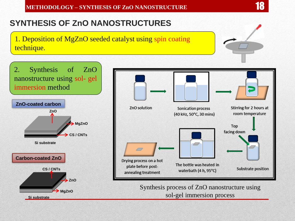
SYNTHESIS OF ZnO NANOSTRUCTURES
METHODOLOGY – SYNTHESIS OF ZnO NANOSTRUCTURE
1. Deposition of MgZnO seeded catalyst using spin coating
technique.
2. Synthesis of ZnO
nanostructure using sol- gel
immersion method
Synthesis process of ZnO nanostructure using
sol-gel immersion process
18
CS / CNTs
ZnO
MgZnO
Si substrate
CS / CNTs
Si substrate
ZnO
MgZnO
ZnO-coated carbon
Carbon-coated ZnO

QUASI-ALIGNED CNTs
Precursor temperature : 500 C
Synthesis temperature : 750 C
Precursor volume : 4 ml
Catalyst concentration : 17.99 wt%
Synthesis time : 30 min
Diameter:
18.0 – 34.0 nm
Length:
14.5 µm
Growth rate:
0.48 µm min-1
FESEM images of quasi-aligned CNTs synthesised from WEO
19
5. RESULTS AND DISCUSSION

20RESULTS AND DISCUSSION – QUASI-ALIGNED CNTs
Q1
IF: 2.269

RESULTS AND DISCUSSION – QUASI-ALIGNED CNTs
18 nm
0.34 nm
5 nm
0.256 nm
10 nm
HRTEM image of quasi-aligned CNTsMicro-Raman
spectrum
TGA and DTA curvesXRD pattern
ID/IG = 0.9
21

GROWTH MECHANISM OF QUASI-ALIGNED CNTs SYNTHESISED FROM WEO
Ferrocene was initially decomposed at around 185 C to form Fe catalyst particles and
deposited on the substrate in the synthesis zone.
Catalytic cracking of WEO into lighter hydrocarbon and other vapour elements:
CxHyOz(l)+H2O(l) Cx’Hy’Oz’(g)+Cx’Hy’(g)+CO(g) +CO2(g)+H2(g)+H2O(g)+OH
The carbon containing elements dissolved and diffused through Fe particles until reached
saturate condition.
The carbon crystallized out to form the walls of CNTs.
When the catalyst activity has lowered, a-C formed attach to the wall of CNTs.
Due to the weak Fe – substrate adhesion, the Fe catalyst was easily lifted upward
encapsulated the inner tube of CNTs
RESULTS AND DISCUSSION – QUASI-ALIGNED CNTs 22

Various synthesis parameters were carried out to optimized theproduction of carbon materials:
• Synthesis temperature : 600 – 1000 C
• Catalyst concentration : 5.33 – 19.99 wt%
• Precursor temperature : 400 – 600 C
• Precursor volume : 3 – 9 ml
• Synthesis time : 10 – 60 minutes
RESULTS AND DISCUSSION – PARAMETERS OPTIMIZATION
Al-Cu alloy nanowires
decorated with CS
CS
2323

RESULTS AND DISCUSSION – CARBON/ZnO COMPOSITE
CNTs/ZnO COMPOSITE
ZnO Nanorods
ZnO-coated CNTs
Diameter :
42.8 – 285.7 nm
Length:
1.5 m
Diameter : 35.7 – 80.0 nm
2525

Sharper hexagonal tip of ZnO structure was observed with the
decrement of rod size.
The supplies of ZnO precursor for the normal growth of ZnO nanorods
decreased due to the interaction between CNTs and ZnO precursor.
MgZnO particles deposited on the carbon materials and served as a
better nucleation site for ZnO nanorods.
RESULTS AND DISCUSSION – CARBON/ZnO COMPOSITE
ZnO-coated CS
26

RESULTS AND DISCUSSION – CARBON/ZnO COMPOSITE
CNTs-coated ZnO
Dense short CNTs with diameter :
32.0 – 44.4 nm
2727

RESULTS AND DISCUSSION – FEE MEASUREMENT
FIELD ELECTRON EMISSION MEASUREMENT
Ability of the sample to emitelectron.
Applications: display (FED),flat lamp, scanning probe.
J vs E curve of CNTs and ZnO nanorods
J vs E curve of CNTs/ZnO composite
Schematic diagram of
FEE measurement
set-up
Fowler-Nordheim equation (Fowler & Nordheim, 1928)
28

RESULTS AND DISCUSSION – FEE MEASUREMENT 29
Field enhancement factor () of material can be calculated from the
slope of ln (J/E2) vs 1/E curve using the equation:
= -B3/2 / slopeCNTs
ZnO
CNTs-coated ZnO
ZnO-coated CNTs

The nature morphology of CNTs with high aspect ratio and small tip radius curvature are
beneficial for FEE application. However, high density of CNTs often led to the screening
effect which made the emission less stable.
ZnO nanomaterials have negative electron affinity (Jin et al., 2009) which can support the
current emission due to their ability to emit electrons to the vacuum with little energy loss.
CNTs-coated ZnO is considered has the best FEE performance with lowest threshold field
and highest current density reached.
RESULTS AND DISCUSSION – FEE MEASUREMENT
Sample Turn On (V/µm)
at 0.1 µA/cm2
Threshold (V/µm)
at 1 µA/cm2
J max (µA/cm2)
CNTs 4.12 7.19 3.63 5161
ZnO 5.65 7.34 3.46 2452
ZnO-coated CS 3.48 6.35 3.78 5879
CS-coated ZnO 6.83 7.88 2.51 755
ZnO-coated CNTs 5.99 6.31 77.8 1803
CNTs-coated ZnO 4.80 5.64 280.0 1558
Table 3. FEE properties of carbon materials and their composite structure
30

7. CONCLUSIONS AND FUTURE WORK
Carbon nanostructured materials including CS, Al-Cu alloy nanowires
decorated with CS and CNTs were successfully synthesized using WEO as
starting material using TCVD method.
Generally, the changes in synthesis parameters affected the morphology,
size and quality of carbon materials. In case of production of CNTs, they also
affected the growth rate of nanotubes.
Production of CS was achieved at higher synthesis temperature (800-900°C)
and lower catalyst concentration (5.33 wt%).
Quasi-aligned CNTs were successfully produced at synthesis and precursor
temperature of 750 and 500°C, respectively using 17.99 wt% catalyst
concentration in 4 ml precursor and the synthesis process lasted for 30 min.
CONCLUSIONS
31

CONCLUSIONS 32
Carbon/ZnO nanostructure composites were successfully synthesized
with different kind of carbon materials (CS and CNTs) and
configurations (carbon-coated ZnO and ZnO-coated carbon).
Quasi-aligned CNTs presented the best FEE performances with lower
turn on (4.12 V/µm) at 0.1 µA/cm2 , highest current maximum of 3.63
µA/cm2.
Generally, the presence of ZnO nanostructures wheatear at the bottom
or on the top of carbon materials has successfully enhanced the FEE
properties of composite materials.
32
The FEE enhancement of the samples was mainly affected by the
morphology and geometrical changes of carbon materials or ZnO
nanostructures which improved the emission site of emitter.
High conductivity of carbon materials also promoted a better
electron transfer and led to the enhancement of field emission.
Moreover, the presence of carbon materials acted as a good additional
catalyst which improved the uniformity and crystal quality of ZnO
nanostructures.
CNTs-coated ZnO sample gave the best FEE performances in term
of the highest current density reached (280.0 µA/cm2) and lowest
threshold field (5.64 V/µm) at 1 µA/cm2
CONCLUSIONS 3333

34
Modified and larger TCVD system with the continuous supply ofprecursor is suggested to be developed for higher production ofcarbon materials.
The use of injection or sprayer system is proposed in order tointroduce the precursor to the system.
For certain applications, in order optimize the performance of carbonmaterials especially CNTs from WEO, purification of the producedsamples is suggested to be done.
Purification of carbon materials can be achieved by post annealingtreatment at high temperature condition or chemical purificationwith acid treatment.
FUTURE WORKS
34

FUTURE WORKS 35
Intensive studies on the other properties of carbon materials from
WEO such as mechanical, optical, thermal and magnetic properties
are needed to be performed in order to expand their applications.
For the composite structure of carbon materials with ZnO, such more
efficient methods which involves lower synthesis temperature should
be considered to minimize the effect on the composite structure.
Composite of carbon materials with other metal oxides or
nanostructured materials can be studied in order to meet the other
desired applications.
35

REFERENCESArnaiz, N., Gomez-Rico, M.F., Gullon, I.M., & Font, R. (2013). Production of carbon nanotubes from
polyethylene pyrolysis gas and effect of temperature. Ind. Eng. Chem. Res. 52(42), 14847-14854.
Datta, A., Dutta, P., Sadhu, A., Maiti, S., & Bhattacharyya, S. (2013). Single-step scalable conversion of waste
natural oils to carbon nanowhiskers and their interaction with mammalian cells. Journal of Nanoparticle
Research, 15(7), 1-15.
Datta, A., Sadhu, A., Sen, B., Kaur, M., Sharma, R., Das, S. C., & Bhattacharyya, S. (2013). Analysis of the
acid, base and air oxidized carbon microspheres synthesized in a single step from waste engine oil.
Corrosion Science, 73, 356–364.
Fowler, R. H., & Nordheim, L. (1928). Electron emission in intense electric fields. Paper presented at the
Proceedings of the Royal Society London, Series A.
Kukovitskii, E. F., Chernozatonskii, L. A., L'Vov, S. G., & Mel'nik, N. N. (1997). Carbon nanotubes of
polyethylene. Chemical Physics Letters, 266(3-4), 323-328.
Li, Y., Wang, H., Wang, G., & Gao, J. (2012). Synthesis of single-walled carbon nanotubes from heavy oil
residue. Chemical Engineering Journal, 211-212, 255-259.
Mopoung, S. (2011). Occurrence of carbon nanotube from banana peel activated carbon mixed with mineral
oil. International Journal of Physical Sciences, 6, 1789-1792.
Oh, E., Lee, J., Jung, S.-H., Cho, S., Kim, H.-J., Lee, S.-H., … Han D. S. (2012). Turning refuse plastic into
multi-walled carbon nanotube forest. Science and Technology of Advanced Materials, 13(2), 025004.
.

Scarselli, M., Castrucci, P., & Crescenzi, M. D. (2012). Electronic and optoelectronic nano-devices based on
carbon nanotubes. Journal of Physics: Condensed Matter, 24(31), 313202
Suriani, A. B., Dalila, A. R., Mohamed, A., Mamat, M. H., Salina, M., Rosmi, M. S., ... Rusop, M. (2013).
Vertically aligned carbon nanotubes synthesized from waste chicken fat. Materials Letters, 101, 61-64.
doi: 10.1016/j.matlet.2013.03.075
Suriani, A. B., Md Nor, R., & Rusop, M. (2010). Vertically aligned carbon nanotubes synthesized from waste
cooking palm oil. Journal of the Ceramic Society of Japan, 118(1382), 963-968. doi:
10.2109/jcersj2.118.963
Wang, J., Hu, Z., Xu, J., & Zhao, Y. (2014). Therapeutic applications of low-toxicity spherical nanocarbon
materials. NPG Asia Materials, 6(2), e84.
37

PUBLISHED PAPERS
1. A.B. Suriani, S. Alfarisa, A. Mohamed, I.M. Isa, A. Kamari, N.H. Hashim, M.H. Mamat, A.R.
Mohamed and M. Rusop, “Quasi-aligned Carbon Nanotubes Synthesised from Waste Engine Oil”.
Materials Letters , 2015, 139 (220-223).
2. S. Alfarisa, A.B. Suriani, A. Mohamed, N. Hashim, A. Kamari, I.M. Isa, M.H. Mamat, A.R.
Mohamed and M. Rusop, “Carbon Nanostructures Production from Waste Materials: A Review”.
Accepted to be published in Advanced Materials Research journal (Proceedings of NANO-
SCITECH 2015).
3. R.N. Safitri, A.B. Suriani, S. Alfarisa, A. Mohamed, N. Hashim, A. Kamari, I.M. Isa, A.R.
Mohamed and M. Rusop, “Zinc Oxide/Carbon Nanotubes Nanocomposites: Synthesis Methods
and Applications”. Accepted to be published in Advanced Materials Research journal
(Proceedings of NANO-SCITECH 2015).
4. J. Norhafizah, A.B. Suriani, S. Alfarisa, J. Rosly, I.M. Isa, A. Mohamed, A. Kamari, N. Hashim
and M. Rusop, “The Effect of Time Interval on Waste Cooking Palm Oil Injection for Carbon
nanotubes Production”. Accepted to be published in Advanced Materials Research journal
(Proceedings of NANO-SCITECH 2015).
5. J. Norhafizah, A.B. Suriani, S. Alfarisa, J. Rosly, I.M. Isa, A. Mohamed, A. Kamari, N. Hashim
and M. Rusop, “Mass Production of Carbon Nanotubes and Its Future Application: A Review”.
Accepted to be published in Advanced Materials Research journal (Proceedings of NANO-
SCITECH 2015).
6. M.D. Norhafizah, A.B. Suriani, S. Alfarisa, I.M. Isa, A. Mohamed, A. Kamari, N. Hashim and
M. Rusop, “A review: Synthesis Methods of Graphene and Its Application in Supercapacitor
Devices”. Accepted to be published in Advanced Materials Research journal (Proceedings of
NANO-SCITECH 2014).
7. M.D. Norhafizah, A.B. Suriani, S. Alfarisa, I.M. Isa, A. Mohamed, A. Kamari, N. Hashim and
M. Rusop, “The Synthesis of Graphene Oxide via Electrochemical Exfoliation Method”.
Accepted to be published in Advanced Materials Research journal (Proceedings of NANO-
SCITECH 2014).
3939

PRESENTATIONS
1. S. Alfarisa, A.B. Suriani, A.R. Dalila, A. Mohamed, I.M. Isa, M.H. Mamat and A.R. Mohamed, “Field
Emission Enhancement of Zinc Oxide Nanorods Grown on Carbon Spheres.”
Presented at 2nd International Postgraduate Conference on Science and Mathematics, Tanjung Malim,
Perak, Malaysia, October 18-19th, 2014.
2. S. Alfarisa, A.B. Suriani, M.H. Mamat A.R. Mohamed and M. Rusop, “The Effect of Catalyst
Concentration on the Synthesis of Carbon Nanotubes from Waste Engine Oil Precursor.”
Presented at Malaysia-Japan International Conference on Nanoscience, Nanotechnology &
Nanoengineering 2014, Shah Alam, Selangor Malaysia, February 28th – March 2nd, 2014.
3. S. Alfarisa, A.B. Suriani, M.H. Mamat A.R. Mohamed and M. Rusop, ”Effect of Synthesis Temperature
on the Growth of Carbon-based Materials.”
Presented at Malaysia-Japan International Conference on Nanoscience, Nanotechnology &
Nanoengineering 2014, Shah Alam, Selangor Malaysia, February 28th – March 2nd, 2014.
4. S. Alfarisa, A.B. Suriani, A.R. Dalila, A.R. Mohamed, M.H. Mamat and M. Rusop, “Synthesis of
copper-aluminium nanowires decorated with carbon spheres from waste engine oil precursor.”
Presented at International Conference on Innovation Challenges in Multidisciplinary Research and
Practice (ICMRP 2013), Kuala Lumpur, Malaysia, December 13th-14th, 2013.
40

AWARDS
1. “Conversion of Waste Materials into Nanostructured Carbon.” Silver Award at Bio
Innovation Award 2014, Kuala Lumpur, Malaysia, November 19th-21st, 2014.
2. “Synthesis of copper-aluminium nanowires decorated with carbon spheres from waste
engine oil precursor.” Best Session Paper Awards at International Conference on
Innovation Challenges in Multidisciplinary Research and Practice (ICMRP 2013), Kuala
Lumpur, Malaysia, December 13-14th, 2013.
41

ACKNOWLEDGEMENTS
• MALAYSIA TORAY SCIENCE FOUNDATION
(MTSF, GRANT REFF: 2012-0137-102-11)
• RESEACH ACCULTURATION COLLABORATIVE
EFFORT (RACE, GRANT REFF: 2012-0147-102-62)
• DEPARTMENT OF PHYSICS, UNIVERSITI
PENDIDIKAN SULTAN IDRIS
42

43