carbon gasification in self-reducing mixtures
TRANSCRIPT

2687 © 2014 ISIJ
ISIJ International, Vol. 54 (2014), No. 12, pp. 2687–2696
Carbon Gasification in Self-reducing Mixtures
Maurício Covcevich BAGATINI,1) Victor ZYMLA,2)* Eduardo OSÓRIO3) and Antônio Cezar Faria VILELA3)
1) Federal University of Minas Gerais (UFMG), Laboratory of Metallurgical Processes, 31.270-901, Belo Horizonte, MG, Brazil.2) Ecole Centrale Paris, Chemical and Materials Engineering Laboratory (LGPM), Grande Voie des Vignes, 92295 Chatenay-Malabry, France. 3) Federal University of Rio Grande do Sul (UFRGS), Iron and Steel Making Laboratory (Lasid/PPGE3M),PO Box 15021, 91501-970 Porto Alegre, RS, Brazil.
(Received on May 28, 2014; accepted on July 28, 2014)
Self-reduction experiments of mill scale with four potential carbonaceous reductants (charcoal, coalchar, blast furnace coke and petroleum coke) were carried out by thermogravimetry (TG) in order tochoose one allowing the highest reduction rate and overall conversion. The fastest rate of self-reductionwas measured for the charcoal and the slowest for the petroleum coke. The Friedman method of kineticsdata analysis was used to calculate apparent activation energy at different conversion rates. Based onthese values it can be concluded that the Boudouard reaction controls the rate of self-reduction with char-coal up to about 60% of conversion and even more for others reductants. It has also been demonstratedthat the morphology of the iron produced strongly depends on reactivity of carbonaceous reductant.
KEY WORDS: scale recycling; self-reduction; Boudouard reaction; thermogravimetry; reductant reactivity;iron morphology.
1. IntroductionIn the steelmaking processes, about 500 kg of solid
wastes of different nature (including blast furnace (BF) andbasic oxygen furnace (BOF) slag) per ton of steel are gen-erated.1) A big part of that is already recycled but the new,more efficient ways of recycling are still explored. One ofthe wastes generated in steel plants is the scale which rep-resents about 2% of the steel produced. It is formed duringthe continuous casting and rolling mill processes when steelis subject to thermal gradients in oxidant atmospheres, whichpromotes the growth of iron oxides layer at the surface ofsteel.2) Such a scale is very rich in iron and generally con-tains three iron oxides - wüstite, magnetite and hematite.3)
In the integrated steel plants, the mill scale is habituallyused as raw material at the sintering plants but the recyclingof this waste has also been reported in the form of briquettesused in BOF steelmaking.4–6) In the case of mini-mills whichoperate using electric arc furnaces (EAF) and where there areno reduction reactors, such as a blast furnace, the scale recy-cling is more difficult and this waste is often sent to landfillsor used in the cement industry. Some authors have alreadyreported the possibility of recycling mill scale in mini-millplants through the introduction of self-reducing briquettes inEAF, but the details are still being investigated.7–9)
The EAF process operates at a lower charge capacity andits time-to-smelt is shorter, in comparison with the reductionreactors. While the reduction reactors require high-strengthself-reducing briquettes to achieve high performance, in theEAF process kinetic phenomena seem to be the most impor-tant parameter. If the iron oxides are not reduced beforecharge melting, it may lead to an increase in the energy con-sumption and a decrease in the metal yield of the process.So, to make the use of self-reducing briquettes viable in anEAF, such agglomerate must have a high kinetics of reduc-
tion of the iron oxides content.The self-reduction (carbothermal reduction) technology
consists essentially of using the agglomerates with an inti-mate mixture between the iron oxides and the reducing car-bonaceous agent, the quantity of which must be sufficient toreduce completely the oxides content. The main chemicalreactions resulting from heating such composites are thecoupled gaseous reduction of iron oxides (1) and gasifica-tion of carbon or Boudouard reaction (2):
............. (1)
.......................... (2)
As these reactions occur in series, one or the other cancontrol the overall reaction rate in the self-reducing compos-ites depending on a variety of experimental conditions suchas the composition (oxide to carbon ratio), form (pellet, bri-quette, packed bed) and size of agglomerate, the heatingregimes and the surrounding atmosphere composition andpressure. As reviewed by Donskoi et al.,10) a vast majorityof researchers claim the Boudouard reaction as a limitingstep of a self-reduction process.11–15) Others propose a mixedcontrol regime with the influence of both reactions (gasifi-cation and reduction)or a mixed gasification and heat trans-fer control regime.16–20) Pure heat transfer control has alsobeen postulated and modelled.21)
These findings are based on different experimentalapproaches such as the continuous weight loss of compositesample, the reactor output gas analysis and the temperatureprofiles inside the composite piece. The influence of theconstituent particles nature and size of iron oxide, carbona-ceous materials and some additives on the kinetics of overallreaction and the magnitude of its apparent activation energyare often used to identify a rate controlling step. The rela-tively high activation energy values (250–350 kJ/mol) aretaken as being characteristic for the Boudouard reactioncontrol while the lower values indicate an increasing role ofreduction in overall self-reduction rate control.10,14) Accord-
* Corresponding author: E-mail: [email protected]: http://dx.doi.org/10.2355/isijinternational.54.2687
Fe O Fe OCO COx y x y(s) (s) + = +−1 2
C CO CO(s)+ =2 2
© 2014 ISIJ 2688
ISIJ International, Vol. 54 (2014), No. 12
ing to Iguchi et al.22–24) the carburization of freshly reducediron by direct carbon dissolution C(s) = [C] is anotherimportant reaction which could interfere in self-reduction,especially at the reduced pressures and high temperatures.
Due to the importance of the Boudouard reaction andregarding several possible reducing agents for use in suchagglomerates, different sources of carbon such as biomasschar, coal, coal char, lignite, metallurgical and petroleumcokes, waste plastics as well as graphite (in some fundamen-tal studies) have been tested.10,22–27) On the other hand, thehematite and magnetite ores, synthetic wustite as well assome waste materials (EAF dust, mill scale) were used asthe iron oxide bearing materials in the self-reducing mix-tures and agglomerates.10,11)
In addition to the reaction rate limits, another importantissue is the mechanical strength of the agglomerates duringthe reduction. It depends to a large extent on the morpholo-gy of the resulting iron, which can lead to some adverseeffects such as swelling and cracking of agglomerate. Thenature of the reductant and temperature profile of self-reduction influence these phenomena.28–30)
The mechanism and kinetics of self-reduction has alreadybeen modelled to better understand the rate phenomena andto optimize the iron oxide/carbon composite technology bybetter selection of constituents and their processing condi-tions.10,18–21,24) These models take into consideration notonly the kinetics of gasification and reduction reactions butalso the mass and heat transfer phenomena and balances.They need precise measures of the involved reactions rateconstants and some structural parameters (porosity, specificsurface, etc.) which influence the chemical reactions andtransport phenomena. The heat transfer is of particularinterest due to strongly endothermic character of Boudouardreaction, it could become the rate-limiting step.21,29)
To find the right way to introduce the self-reducing bri-quettes in the EAF, it is crucial to evaluate the characteristicsof the raw materials to predict its self-reduction performanceunder such conditions. Bearing this in mind, the scale usedin this work was first characterized and its reduction behav-iour in pure CO and CO–CO2 mixtures was investigated.3)
In the next step, which was the goal of this work, four car-bonaceous materials was evaluated as the potential scalereducing agents for the self-reducing briquettes to use in theEAFs. For that gasification kinetics of each reductant bypure carbon dioxide was first measured and next the self-reduction tests were performed in order to determine the rateand controlling steps of process. Moreover, the influence ofreductant on the morphology of produced iron was investi-gated to better understand the mechanism of self-reduction.
2. Experimental2.1. Materials
The scale used in this work was provided by a mini-millplant. It was sampled and prepared according to the propor-tion generated in the continuous casting and rolling mill.The chemical composition of the scale is presented in Table1(a) and the phase analysis by Mössbauer spectroscopy isgiven in Table 1(b). The content of reducible oxygen in thescale, calculated from both analysis and confirmed by gas-eous reduction of scale, is 22.3 mass%.3)
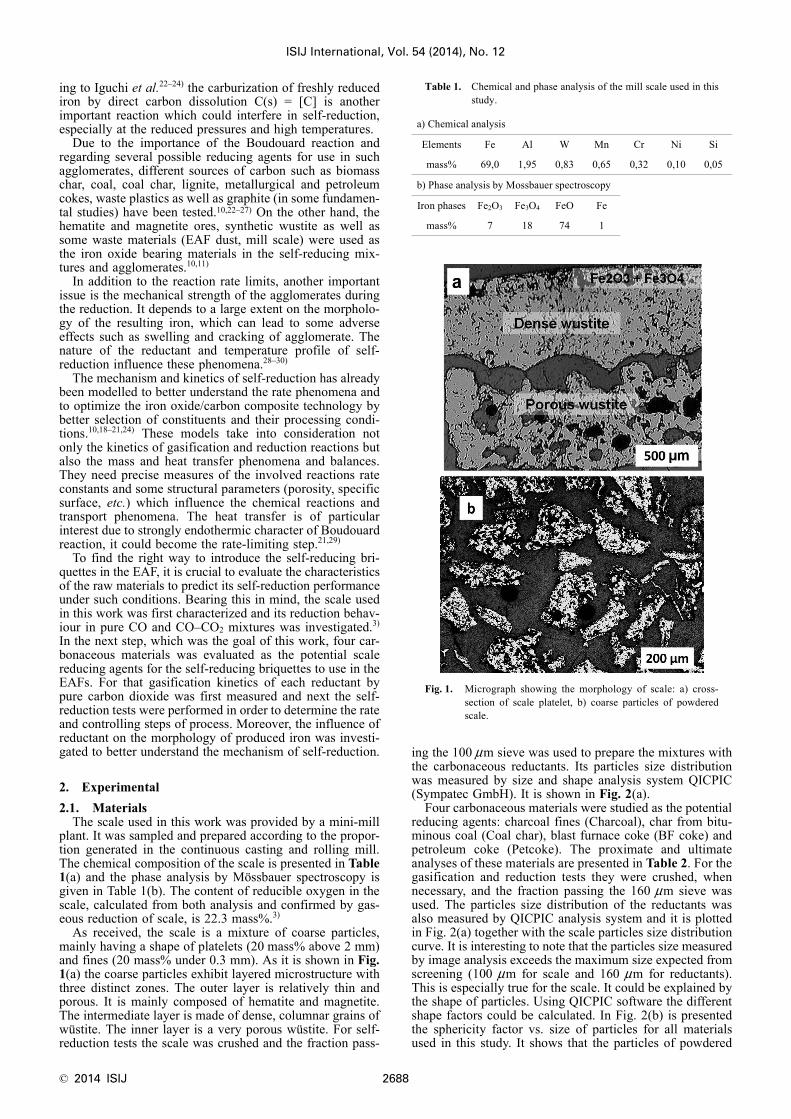
As received, the scale is a mixture of coarse particles,mainly having a shape of platelets (20 mass% above 2 mm)and fines (20 mass% under 0.3 mm). As it is shown in Fig.1(a) the coarse particles exhibit layered microstructure withthree distinct zones. The outer layer is relatively thin andporous. It is mainly composed of hematite and magnetite.The intermediate layer is made of dense, columnar grains ofwüstite. The inner layer is a very porous wüstite. For self-reduction tests the scale was crushed and the fraction pass-
ing the 100 μm sieve was used to prepare the mixtures withthe carbonaceous reductants. Its particles size distributionwas measured by size and shape analysis system QICPIC(Sympatec GmbH). It is shown in Fig. 2(a).
Four carbonaceous materials were studied as the potentialreducing agents: charcoal fines (Charcoal), char from bitu-minous coal (Coal char), blast furnace coke (BF coke) andpetroleum coke (Petcoke). The proximate and ultimateanalyses of these materials are presented in Table 2. For thegasification and reduction tests they were crushed, whennecessary, and the fraction passing the 160 μm sieve wasused. The particles size distribution of the reductants wasalso measured by QICPIC analysis system and it is plottedin Fig. 2(a) together with the scale particles size distributioncurve. It is interesting to note that the particles size measuredby image analysis exceeds the maximum size expected fromscreening (100 μm for scale and 160 μm for reductants).This is especially true for the scale. It could be explained bythe shape of particles. Using QICPIC software the differentshape factors could be calculated. In Fig. 2(b) is presentedthe sphericity factor vs. size of particles for all materialsused in this study. It shows that the particles of powdered
Table 1. Chemical and phase analysis of the mill scale used in thisstudy.
a) Chemical analysis
Elements Fe Al W Mn Cr Ni Si
mass% 69,0 1,95 0,83 0,65 0,32 0,10 0,05
b) Phase analysis by Mossbauer spectroscopy
Iron phases Fe2O3 Fe3O4 FeO Fe
mass% 7 18 74 1
Fig. 1. Micrograph showing the morphology of scale: a) cross-section of scale platelet, b) coarse particles of powderedscale.

ISIJ International, Vol. 54 (2014), No. 12
2689 © 2014 ISIJ
scale (especially the bigger ones, >100 μm) have less spher-ical, but more elongated shape then carbonaceous materials.This elongated shape of scale particles, seen also at themicrograph in Fig. 1(b), results from the cleavage of layeredstructure of the parent scale platelets.3)
2.2. Reductants Gasification in Pure Carbon DioxideThe reactivity of all carbonaceous materials towards car-
bon dioxide was first measured by Netzsch STA 409 PCLuxx thermobalance using the procedure with stepwise tem-perature increase, established in the previous studies oncoke reactivity.32,33) A sample of powdered reductant withmass about 50 mg was poured into an alumina crucible of6 mm in inner diameter and 5 mm in height. The sample wasfirst heated up to 1 100°C under nitrogen and kept at thistemperature for 10 minutes in order to release the residualvolatile matters. Then, the temperature was lowered to800°C. After that nitrogen was replaced by carbon dioxide
(300 ml/min) and a set of reaction rate measurements fol-lowed. The sample was kept at 800, 850, 900, 950, 1 000,1 050 and 1 100°C successively for different periods of time(ranging from 60 to 10 minutes), sufficient to observe stablegasification rate at each temperature plateau. This procedurelimits number of experiments needed to measure the influ-ence of temperature on gasification rate. It is worth to notethat care was taken to not exceed 20% of cumulated samplefractional mass loss in order to prevent the influence of frac-tional gasification on the gasification rate as it was welldemonstrated by Turkdogan and Vinters.31)
2.3. Self-reduction KineticsThese tests were carried out to verify the kinetic behav-
iour of self-reducing mixtures with different reducing agentsand scale as the source of iron oxides. To avoid the influenceof residual volatiles on the reduction, all carbonaceousreducing agents were first heated under nitrogen up to1 100°C and then, after soaking during 10 minutes, cooleddown. Such devolatilised reductants were blended withscale at the reductant/scale ratio of 1/4 (by weight), givinga C/O molar ratio of about 3/2. The sample of self-reducingmixture with mass about 200–400 mg was poured into analumina crucible having the same inner diameter as for gas-ification (6 mm) but higher (10 mm). Figure 3 shows thepolished cross-section of the crucible with the mixture of BFcoke and scale after about 50% of fractional mass loss. Thebulk density of the samples inside the crucible was 0.3–0.4g/cc for reducing agents and 1.2–1.3 g/cc for self-reducingmixtures. The self-reduction kinetics measurements werecarried out under non-isothermal conditions using the sameNetzsch thermobalance as in the gasification tests. In thefirst series of study, the self-reduction kinetics was mea-sured at a heating rate of 20 K/min. However, to betterassess the apparent activation energy of self-reduction, inthe second series, for two of them (charcoal and BF coke),the reduction rate was measured at a different heating rate(ranging from 3 to 40 K/min).
In order to have a better insight into the self-reductionmechanism, the microscopic examination of partiallyreduced samples has been performed with a metallographicoptical microscope (Reichert-Jung MeF3) on polished sam-ples (mounted on epoxy resin).
3. Results and Discussion3.1. Gasification Rate of Carbonaceous Reductants
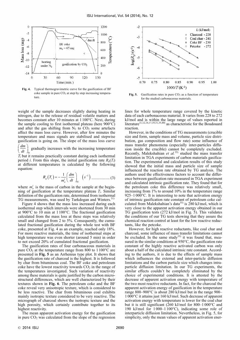
Figure 4 explains a typical thermogravimetric curve forthe gasification of reductant (BF coke) in pure CO2. The
Fig. 2. Particles size distribution (a) and shape factor - sphericityversus particles size (b) measured by image analysis.
Table 2. Proximate and ultimate analysis of solid carbonaceousreductants.
SampleProximate analysis (mass%) db Ultimate analysis (mass%) daf
Ash VolatileMatter
FixedCarbon C H N S O
Charcoal 2.0 20.1 77.8 85.8 3.17 1.07 0.08 9.97
Coal char 11.3 4.2 84.5 89.3 3.75 1.58 1.01 4.37
BF coke 10.5 1.1 88.5 96.2 0.54 1.23 0.78 1.25
Petcoke 0.9 7.5 91.6 92.8 3.25 2.42 0.79 0.69
db – dry basis, daf – dry and ash free basis
Fig. 3. Cross-section of alumina crucible with the mixture of scaleand BF coke after partial reduction showing the cruciblesize and shape as well as the main sample characteristics forself-reduction tests (a) and gasification tests (b).
© 2014 ISIJ 2690
ISIJ International, Vol. 54 (2014), No. 12
weight of the sample decreases slightly during heating innitrogen, due to the release of residual volatile matters andbecomes constant after 10 minutes at 1 100°C. Next, duringthe sample cooling to first isothermal plateau (here 900°C)and after the gas shifting from N2 to CO2 some artefactsaffect the mass loss curve. However, after few minutes thetemperature and mass signals are stabilised and stepwisegasification is going on. The slope of the mass loss curve
gradually increases with the increasing temperature
Ti but it remains practically constant during each isothermalperiod i. From this slope, the initial gasification rate Rg(Ti)at different temperatures is calculated by the followingequation:
.................. (3)
where is the mass of carbon in the sample at the begin-ning of gasification at the temperature plateau Ti. Similardefinition of the gasification rate, determined from isothermalTG measurements, was used by Turkdogan and Winters.31)
Figure 4 shows that the mass loss increased during eachisothermal step which intervals were shortened from 30 minat 900°C to 10 min at 1 100°C. The fractional gasificationcalculated from the mass loss at these steps was relativelysmall and changed from 2 to 5%. Consequently, the cumu-lated fractional gasification during the whole test with BFcoke, presented at Fig. 4 as an example, reached only 18%.For more reactive materials, the time of isothermal steps athigh temperature was even shorter (around 5 min) in orderto not exceed 20% of cumulated fractional gasification.
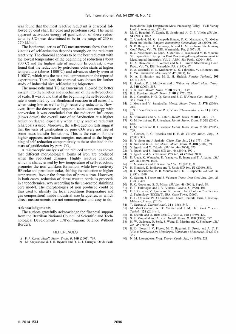
The gasification rates of four carbonaceous materials inpure CO2 at the temperature range from 800 to 1 100°C arepresented in Fig. 5 as an Arrhenius type plot. It shows thatthe gasification rate of charcoal is the highest. It is followedby char from bituminous coal. The BF coke and petroleumcoke have the lowest reactivity towards CO2 in the range ofthe temperatures investigated. Such variation of reactivityamong these materials is quite justified by the carbon micro-structural differences, which are well characterized by theirtextures shown in Fig. 6. The petroleum coke and the BFcoke reveal very anisotropic texture, which is considered tobe less reactive. The char from bituminous coal exhibitsmainly isotropic texture considered to be very reactive. Themicrograph of charcoal shows the isotropic texture and thehigh porosity, which certainly contribute together to itshighest reactivity.
The mean apparent activation energy for the gasificationin pure CO2 was calculated from the slope of the regression
lines for whole temperature range covered by the kineticdata of each carbonaceous material. It varies from 228 to 272kJ/mol and is within the large range of values reported inliterature11,12,14,17,19,31,35,40) as characteristic for the Boudouardreaction.
However, in the conditions of TG measurements (cruciblesize and form, sample mass and volume, particle size distri-bution, gas composition and flow rate) some influence ofmass transfer phenomena (especially inter-particles diffu-sion inside the crucible) cannot be completely excluded.Recently, Malekshahian et al.35) studied the mass transferlimitation in TGA experiments of carbon materials gasifica-tion. The experimental and calculation results of this studyshowed that the initial mass and particle size of sampleinfluenced the reaction rate obtained by TG analysis. Theauthors used the effectiveness factors to account the differ-ence between gasification rate measured in TGA experimentand calculated intrinsic gasification rate. They found that forthe petroleum coke this difference was relatively small,increasing from 1% to around 10% in the temperature range925–1 000°C. It is interesting to note that activation energyof intrinsic gasification rate constant of petroleum coke cal-culated from Malekshahian’s data35) is 280 kJ/mol, which isvery close to the apparent activation energy obtained in ourTG gasification tests (272 kJ/mol in Fig. 5). This validatesthe conditions of our TG tests showing that they assure thechemical reaction control at least for the low reactive reduc-tants, like the petcoke.
However, for high reactive reductants, like coal char andcharcoal, some influence of mass transfer limitations cannotbe excluded. In the same study35) it was found that, mea-sured in the similar conditions at 950°C, the gasification rateconstant of the highly reactive activated carbon was onlyabout a half of the calculated intrinsic rate constant. Accord-ing to the authors, it is due to the effects of sample masswhich influences the external and inter-particle diffusionlimitations and the carbon particle size which changes intra-particle diffusion limitation. In our TG experiments, thesimilar effects couldn’t be completely eliminated by thechoice of experimental conditions. It is attested by thedecrease of apparent activation energy with temperature ofthe two most reactive reductants. In fact, for the charcoal theapparent activation energy of gasification in the temperaturerange 800–900°C is about 280 kJ/mol but in the range 900–1 000°C it attains just 160 kJ/mol. Such decrease of apparentactivation energy with temperature is lower for the coal charbut it is still significant (260 kJ/mol for 800–1 000°C and190 kJ/mol for 1 000–1 100°C), indicating some role ofinterparticle diffusion limitation. Nevertheless, in Fig. 5, forsimplicity, only the mean values of apparent activation ener-
Fig. 4. Typical thermogravimetric curve for the gasification of BFcoke sample in pure CO2 at step by step increasing tempera-ture.
dmdt i
⎛⎝⎜
⎞⎠⎟0
R Tm
dm
dtsg i
oi
i
( ) = − ⎛⎝⎜
⎞⎠⎟ ( )−1
0
1
moi
Fig. 5. Gasification rates in pure CO2 as a function of temperaturefor the studied carbonaceous materials.

ISIJ International, Vol. 54 (2014), No. 12
2691 © 2014 ISIJ
gy of gasification are shown because, even more or lessinfluenced by mass transfer limitations, they are noticeablyhigher than apparent activation energy of reduction withwhich they are further compared in order to find the reactionwhich influences more the self-reduction rate.
3.2. Self-reduction Rates with Different ReductantsFigure 7 shows the mass loss curves obtained with the
different self-reducing mixtures during the non-isothermalruns at a heating rate of 20 K/min up to 1 100°C. For thesample of scale mixed with charcoal, the reduction startedat about 850°C and was very fast. Consequently, it was com-pleted before the sample reached 1 100°C. The reductionrate of scale mixed with the char from bituminous coal wasclose to that measured with charcoal, but somewhat slower.On the other hand, the mass loss of the samples containingblast furnace and petroleum coke started at a higher temper-ature (about 950°C and 1 000°C, respectively) and thereduction rate was much slower, being however higher forthe blast furnace coke than for the petroleum coke. It is thusworth to note that the self-reduction rate by these fourreductants corresponds quite well to their rate of gasificationin pure CO2, where charcoal was the most reactive, followedby coal char, BF coke and petcoke. A similar ranking ofreductants was reported recently by Murakami and Kasai26)
who studied the reduction mechanism of iron oxide-carboncomposite with reactive char obtained by pyrolysis of poly-ethylene and compared it with other carbonaceous reduc-tants (charcoal, metallurgical coke and graphite).
3.3. Limiting Reaction StepTo get a better insight into the self-reduction mechanism
and the limiting reaction step, a non-isothermal series of TGmeasurements at different heating rates were carried out for
two reductants: the high reactive charcoal and the low reac-tive blast furnace coke.
Figures 8 and 9 show the curves of mass loss versus timeobtained in these series respectively with charcoal and BFcoke as a reductant. Both figures reveal that self-reductionis completed when the relative mass loss reaches about 32mass%. Consequently, this maximum fractional mass losswas used to calculate the conversion α defined as
........................... (4)
where Δm(t) is the mass loss at time t, msample is the initialmass of sample and 0.32 msample represents the total maxi-mum sample mass loss when self-reduction is finished. This
Fig. 6. Typical textures of four carbonaceous reductants: a) charcoal - porous and isotropic, b) coal char – isotropic, c) BFcoke – anisotropic, d) petroleum coke – anisotropic.
Fig. 7. Mass loss curves of four self-reducing mixtures during theheating up to 1 100°C.
α ( )( )
.t
m t
msample
=Δ
0 32

© 2014 ISIJ 2692
ISIJ International, Vol. 54 (2014), No. 12
mass loss is a sum of gasified carbon and reduced oxygenescaping from the crucible as carbon monoxide and dioxide.Assuming that in escaping gas the carbon is only in form ofCO, the “theoretical fractional mass loss” was calculatedfrom reducible oxygen content in scale (22.3%) and self-reducing mixture composition. It is equal to 31%, which isthe value very close to mean measured 32%.
Figures 10 and 11 show the mass loss curves from Figs.8 and 9 transformed into the conversions versus temperaturecurves, but just for the non-isothermal period. These figuresdemonstrate that for the chosen TG conditions (temperaturemaximum 1 100°C for charcoal and 1 200°C for BF coke) itwas not always possible to complete reaction below themaximum test temperature (during non-isothermal period),
especially in the runs with high heating rate. From the kineticcurves obtained with different heating rate (dT/dt), accord-ing to well known Friedman method,34) the conversion rate(dα/dt) at different conversion α was calculated and plottedon the Arrhenius type diagrams presented in Figs. 12 and13. From these plots the apparent activation energy of self-reduction reaction at different conversion degrees were cal-culated.
Fig. 8. The mass loss curves for different heating rates with char-coal as reductant.
Fig. 9. The mass loss curves for different heating rates with BFcoke as reductant.
Fig. 10. Conversion versus temperature for different heating rateswith charcoal as reductant.
Fig. 11. Conversion versus temperature for different heating rateswith BF coke as reductant.
Fig. 12. Friedman plot of self-reduction data with charcoal asreductant.
Fig. 13. Friedman plot of self-reducing data with BF coke asreductant.

ISIJ International, Vol. 54 (2014), No. 12
2693 © 2014 ISIJ
It is seen at these figures that the apparent activation energyat the low conversions (< 0.6) is relatively high. It rangesfrom 370 to 280 kJ/mol and corresponds well to the valuesreported as characteristic for carbon gasification by CO2under a purely chemical control.14,17,31,35,40) These values areeven slightly higher than those obtained from the gasifica-tion tests with pure carbon dioxide (Fig. 5). Therefore, theysuggest that in the self-reducing mixtures the gasification ofcarbon by CO2 restored via indirect reduction of wustiteoccurs without external and interparticle diffusion limitationdue to the intimate contact of reactants. This is especiallytrue at low conversion (α =0.1) which was reached in therelatively low temperatures (850–950°C with charcoal and1 000–1 050°C with BF coke). It is also worth to note herethat the reduced value of apparent activation energy of char-coal gasification by pure CO2 in the high temperature range(160 kJ/mol) is quite a one-half of 320 kJ/mol measured inself-reduction test. Such a relation (Ekinet/2 = Ediff is consid-ered, since the fundamental works of Walker et al. (inLaurendeau40)) on the porous carbon gasification, as theclear sign that the gasification is controlled by diffusion.
Furthermore, when charcoal is used as reductant (Fig. 12),the progressive decrease of apparent activation energy withincreasing conversion (and temperature) from 320 kJ/mol atα =0.1 to 115 kJ/mol at α =0.9 is observed. Unfortunately,the last value is a very rough estimation from only threepoints of data. Nevertheless, it fits well with trend of theactivation energy diminution apparent already at lower con-version which can be explained by the increasing role ofreduction in the overall self-reduction rate. In fact, the rateof iron oxides reduction decreases with fractional reductionand it also should be true for the scale used in this study.The activation energy of the fine iron oxide reduction byCO reported by Moon and Sahajwalla varie from 36 to 75kJ/mol.14) Fortini and Fruehan17) estimate the activationenergy of wustite reduction by CO as high as 168 kJ/molwhich is a bit higher then upper limit of the 60–150 kJ/molrange given by Coetze et al.19) In our previous work3) on thereduction of the scale by CO, the activation energy of reac-tion rate constant was found to be about 80 kJ/mol. It was alsoobserved that the gaseous reduction of scale occurs accordingto the shrinking core model under chemical control, i.e. thereduction rate decreases with fractional reduction F propor-tionally to (1–F)2/3. It means that in the self-reduction pro-cess the reaction of reduction slows down when the totalconversion increases and thus, progressively, it can becomea limitation for the overall self-reduction rate. This is espe-cially true for high reactivity reductant (like charcoal),which reacts sufficiently fast in the temperature range wherethe reduction rate of iron oxide is relatively low due to itsfeeble initial reducibility or it becomes low when fractionalreduction increases. In the non-isothermal self-reductionwith BF coke presented at Fig. 13 such clear decrease ofapparent activation energy doesn’t appear. That could beexplained by the relatively low maximum conversion (0.6)for which the energy could be calculated due to the availablekinetics data limited by the maximal temperature in our TGmeasurements (1 200°C). However, it is seen from thisseries of data that, like for the charcoal, the apparent activa-tion energy of self-reduction is, in the large range of con-version, clearly higher than that which was measured forpure gasification of BF coke by CO2.
The role of reduction as a partially limiting reaction inself-reduction, which appears especially in the kineticsseries with charcoal, is supported by some previous workson the self-reduction of different iron oxides by differentcarbon materials. Fortini and Fruhan17,18) analysing thereduction of wustite/carbon composites claim that reductionof wustite has a significant effect on the overall rate of self-reduction at the temperature above 1 086°C. The conclu-
sions of Srinivassan and Lahiri16) go even further becausethey assert that the decrease of apparent activation energyfrom about 400 kJ/mol at the beginning (20% of reduction)to 56 kJ/mol at the late stage of reaction (80% of fractionalreduction) proves that the reaction limiting overall self-reduction rate changes from the carbon gasification to thereduction of wustite. On the other hand, Moon andSahajwalla14) analysing the variation of the apparent activa-tion energy of self-reduction with the reductants of differentreactivity (due to its nature or changed by catalyst addition)come to the conclusion that even in moderate temperatureof 1 000°C the increase of reductant reactivity can decreasethe limiting role of gasification. Thus, the self-reduction ratecan shift from the Boudouard reaction control to the mixedBoudouard reaction/wustite reduction control regime.
Figure 14 resumes the results of kinetic study, specificallythe effect of reductants reactivity and iron oxides reducibilityon the controlling steps of self-reduction in non-isothermalconditions (progressive temperature increase). During aheating, the self-reduction starts when carbon gasificationallows a regeneration of carbon oxide and thus maintaininga sufficient reduction potential inside the self-reducing mix-ture. When a highly reactive reductant (like charcoal) isused this happens at about 800°C. However, with a lowreactivity reductant (like BF coke or Petcoke) this arrives atabout 950°C or more. Nevertheless, in this temperaturerange (800–1 000°C) the gasification rate is still lower thanthe possible gaseous (indirect) reduction rates and by con-sequence it controls the overall rate of self-reduction. Athigher temperatures, above 1 100°C, it is possible that theself-reduction shifts from the gasification control regime toa mixed gasification/reduction or even a pure reduction con-trol regime. This is possible firstly due to the accelerationof Boudouard reaction, owing to its significantly higher acti-vation energy, which varies from 200 to 400 kJ/mol whilewustite reduction activation energy is in the range from 60to 150 kJ/mol. Secondly, it is possible due to the relativeslow down of reduction rate when reduction degree increas-es. Thus, the reaction control regime establishes not only theoverall self-reduction rate but it also sets up a reduction gascomposition within the self-reducing mixture. This composi-tion approaches wustite/iron equilibrium when gasification isthe controlling step or moves close to Boudourd reactionequilibrium when reduction controls overall self-reductionrate as it was experimentally showed by Moon andSahajvalla.14)
Fig. 14. Schematic representation of the reactions rate controlregimes in self-reduction mixtures with the reductants ofdifferent reactivity. (the activation energy range for thegasification reaction (*) according to Refs. 11), 14), 17),19), 31), 35), 40) and for the gaseous reduction of ironoxides (**) as reviewed in Refs. 14), 17), 19)).

© 2014 ISIJ 2694
ISIJ International, Vol. 54 (2014), No. 12
The rate limiting factors that we depict in Fig. 14 arebased on our study of self-reduction in the temperature range800–1 100°C. However, at higher temperature (1100°C andabove) additional reactions and physical phenomena couldinterfere in the self-reduction mechanism modifying thereaction kinetics and the reduced iron morphology asshowed Iguchi at all.22,23) These reactions are the carburiza-tion of freshly reduced iron by solid carbon dissolution: C =[C] and the direct reduction of wustite: FeO+[C] = Fe+CO.The direct reduction via carbon dissolution and diffusion insolid iron shell could thus compete with indirect reductionof wustite by carbon oxide restored via Boudouard reaction.With regard to this competition it is interesting to note thatability of carbonaceous matter to dissolve in iron (solid orliquid) depends on carbon crystallinity and is, roughlyspeaking, inversely proportional to its reactivity to carbondioxide. Moreover, the carbon dissolution in iron is promot-ed by good contact between the particles of iron oxide andreducing agent, it means by relatively low mixture porosity(or interparticles void fraction). In contrary, Boudouardreaction kinetics needs rather high porosity (or void frac-tion) of self-reducing mixture to assure good interparticlesdiffusion conditions for gaseous reactants (CO and CO2).
Finally, it should be noted that the conditions of self-reduction at high temperatures can also be modified by theappearance of a liquid phase resulting from melting of ash-es, gangue, mineral additives as well as reduced and carbur-ized iron. Thus, taking all that into account, it is clear thatcontrolling step changes when reduction progresses and thisall the more so because in non-isothermal conditions thetemperature of self-reducing mixture rises at the same timeas fractional reduction progresses.
All discussed above the rate limiting factors fit well withthe self-reduction in laboratory conditions where the rela-tively small samples, in form of crucible with purred powderor small (few millimetres in size) pellets or briquettes, areused. In such the samples and under a relatively low heatingrate, a temperature gradient inside the reacting mixturecould be neglected. However, for the pellets and briquettesof few centimetres in size, destined to industrial uses, theheat transfer could also interfere in the self-reducing processand become the rate controlling factor.21,29)
3.4. Morphology of Reduced IronIt is well known that the morphology of metallic iron pro-
duced from wustite depends on the reduction conditions,mainly the temperature and the reducing gas composition(specifically CO2/(CO+CO2) ratio).36,37) According toGudenau et al.38) there are three types of iron morphologies:layered dense iron, porous iron and directed-whiskers.
In fact, in our earlier study3) on gaseous reduction ofscale, two different morphologies of iron were observed: theporous iron, which prevailed in the samples reduced at high-er temperatures (1 100°C and 1 200°C), and the iron whiskersformed in the scale samples reduced at lower temperatures(900°C and 1 000°C). It was thus interesting to examine andcompare the morphology of iron produced with differentsolid carbonaceous materials, in order to identify the condi-tions in which the self-reducing reactions occur.
Micrographs in Figs. 15(a) and 15(b) clearly show thatself-reduction of scale with charcoal produces iron in formof whiskers, growing on the shrinking core of parent wustiteparticles. These iron whiskers have similar size and shapeas those observed for gaseous reduction of scale at lower
Fig. 15. Partially reduced particles of scale: a) and b) reduced by charcoal (in the non-isothermal test with 20 K/min up to1 100°C) and exhibiting an iron shell made of whiskers; c) and d) reduced by petroleum coke (in the isothermaltest at 1 100°C) and exhibiting a shell of porous iron.

ISIJ International, Vol. 54 (2014), No. 12
2695 © 2014 ISIJ
temperatures (900–1 000°C). The morphology of iron atteststhat the self-reduction occurs at a relatively low temperatureand it agrees with the kinetic measurements (Fig. 5), whichshow that during the heating the self-reduction of scale bycharcoal starts at about 800°C and it is almost completedbelow 1 100°C.
However, the micrographs presented in Figs. 15(c) and16(d) show that self-reduction of scale with BF coke pro-duces a porous iron, which is characteristic of higher tem-perature of reduction. In fact, the kinetic curve relating toBF coke used as a reductant (Fig. 5), shows that the reduc-tion starts at temperature above 1 000°C and around 90% ofconversion occurs during the isothermal step at 1 100°C.Consequently, the formation of porous iron is clearly gov-erned by such high temperature reduction conditions.
The results of the morphological study of iron producedby self-reduction could be compared with that reported byNascimento et al.,28) who studied the microstructure of self-reducing pellets bearing iron ore and carbon. They alsofound that the typical morphology of reaction product in thestep wustite to metallic iron was iron whiskers in the tem-perature range from 950 to 1 050°C and porous iron at atemperature higher than 1 150°C.
It is also worth to note that the micrographs of partiallyreduced scale, as that presented in Figs. 15(c) and 15(d),show that even such small particle of 50 μm in size exhibitsan un-reacted core of dense wustite and porous shell ofreduced iron.
Figure 16 summarises schematically the findings of kinet-ic study together with the results of morphological analysisin order to explain the growth of different iron forms duringself-reduction based on the mechanisms of gaseous reduc-tion proposed by Rist et al.36,37) and Gudenau et al.38)
According to these authors, the formation of iron of differ-ent morphology is due to the relative rate of two broadmechanisms that operate simultaneously. The first of themis oxygen removal, involving transport in the gas phase out-side the particle and reaction on the particle surface. Thesecond is iron transport in wustite based on vacancy diffu-sion. The most important factors affecting the gaseousreduction mechanism are: gas composition which sets up itsreducing potential and temperature which influences notonly the rate of oxygen removal at the particle surface butalso affects the iron transport inside wustite particle. Otherinfluencing factors are the surface characteristics of wustitewhich impacts the iron nucleation density and rate as well
as the solute cations which affect iron transport in wustiteparticles.
In gaseous reduction, a layered dense iron is formed atrelatively low temperature (600–750°C) when wustite isexposed in atmosphere with high reduction potential whichleads to high iron nucleation density. However at such tem-perature range the mobility of ions in wustite is relativelylow and the iron nuclei can grow only laterally at the particlesurface to form a dense iron layer enclosing the un-reactedwustite core. This form of iron was not observed in ourstudy.
At intermediate temperature range (800–900°C) the lowerreduction potential of gas, the lower nuclei density togetherwith a relatively high diffusion rate of iron in wustite pro-mote whiskers growth. Apparently such the conditionsoccur within self-reduction mixture when high reactivereductant, like charcoal is used, allowing sufficient gasifica-tion rate in the temperature range 800–1 000°C. Finally, athigh temperature range (1 000–1 200°C) a high reductionpotential, a high nuclei density together with high iron dif-fusion rate in wustite favour growth of porous iron. In self-reduction experiences the low reactive reductants (BF cokeand petcoke) shift both gasification and reduction reactionsto this high temperature range thus creating conditionswhich enable formation of porous iron.
Once more it should be stressed that this study concernsthe relationship between the reducing agents reactivity andformed iron morphology obtained with self-reducing mix-tures in the temperature range 800–1 100°C. At highertemperature (above 1 100°C), the direct reduction and ironcarburization change not only the reaction kinetics but alsomodify the reduced iron morphology. Iguchi and Endo23)
observed the coalescence of reduced and carburized ironparticles at temperature above 1 150°C depending on thecarburizing abilities of carbonaceous reducing agent. Finally,Flores et al.39) observed a partial or complete melting ofself-reducing mixture of scale and petcoke in the tempera-ture range of 1 300–1 500°C due to the reduced iron carbur-ization.
4. ConclusionsFour carbonaceous materials were studied as the potential
reductants for self-reducing briquettes allowing recyclingmill scale in an EAF. Firstly, their kinetics of gasification inpure carbon dioxide was measured by thermogravimetry. It
Fig. 16. Influence of reductants reactivity on the morphology of iron produced by self-reduction.
© 2014 ISIJ 2696
ISIJ International, Vol. 54 (2014), No. 12
was found that the most reactive reductant is charcoal fol-lowed by coal char, BF coke and petroleum coke. The meanapparent activation energy of gasification of these reduc-tants by CO2 was determined to be in the range of 230 to270 kJ/mol.
The isothermal series of TG measurements show that thekinetics of self-reduction depends strongly on the reductantreactivity. The charcoal appears to be the best reductant withthe lowest temperature of the beginning of reduction (about800°C) and the highest rate of reaction. In contrast, it wasfound that the reduction by petroleum coke starts at highertemperature (above 1 000°C) and advances slowly even at1 100°C, which was the maximal temperature in the reportedexperiments. Therefore, the charcoal was chosen for furtherstudy of industrial size self-reducing briquettes.
The non-isothermal TG measurements allowed for betterinsight into the kinetics and mechanism of the self-reductionof scale. It was found that at the beginning the self-reductionrate is controlled by the Boudouard reaction in all cases, i.e.when using low as well as high reactivity reductants. How-ever, from the decrease of apparent activation energy withconversion it was concluded that the reduction influences(slows down) the overall rate of self-reduction at a higherreduction degree, especially when highly reactive reductant(charcoal) is used. Moreover, the self-reduction tests suggestthat the tests of gasification by pure CO2 were not free ofsome mass transfer limitations. This is the reason for thehigher apparent activation energies measured at the begin-ning of self-reduction comparatively to these obtained in thetests of gasification by pure CO2.
A microscopic analysis of the reduced sample has shownthat different morphological forms of iron are producedwhen the reductant changes. Highly reactive charcoal,which is characterised by low temperature of self-reduction,promotes the iron whiskers formation, while low reactivityBF coke and petroleum coke, shifting the reduction to highertemperature, favour the formation of porous iron. However,in both cases, reduction of dense wustite particles proceedsin a topochemical way according to the un-reacted shrinkingcore model. The morphologies of iron produced could bethus used to identify the local conditions (temperature andgas composition) inside industrial size briquettes, in whichdirect measurements are not commonplace and easy to do.
AcknowledgementsThe authors gratefully acknowledge the financial support
from the Brazilian National Council of Scientific and Tech-nological Development - CNPq/Program: Science WithoutBorders.
REFERENCES
1) P. J. Koros: Metall. Mater. Trans. B, 34B (2003), 769.2) M. Krzyzanowski, J. H. Beynon and D. C. J. Farrugia: Oxide Scale
Behavior in High Temperature Metal Processing, Wiley - VCH VerlagGmbH, Weinheinm, (2010).
3) M. C. Bagatini, V. Zymla, E. Osorio and A. C. F. Vilela: ISIJ Int.,51 (2011), 1072.
4) T. Umadevi, M. G. Sampath Kumar, P. C. Mahapatra, T. MohanBabu and Madhu Ranjam: Ironmaking Steelmaking, 36 (2009), 409.
5) S. R. Balajee, P. E. Callaway, Jr. and L. M. Keilman: SteelmakingConf. Proc., Vol. 78, ISS, Warrendale, PA, (1995), 51.
6) R. C. Nascimento, G. Lenz, D. Martins, C. Takano and M. B. Mourão:5th Japan-Brazil Symp. on Dust Processing-Energy-Environment inMetallurgical Industries, Vol. 5, ABM, São Paolo, (2004), 507.
7) D. A. Dukelow, J. P. Werner and N. H. Smith: Steelmaking Conf.Proc., Vol. 78, ISS, Warredale, PA, (1995), 67.
8) N. A. Godinski, N. N. Kushnarev, D. S. Yakhshuk, V. I. Kotenev andE. Yu. Barsukova: Metallurgist, 47 (2003), 16.
9) N. A. El-Hussiny and M. E. H. Shalabi: Powder Technol., 205(2011), 217.
10) E. Donskoi, D. L. McElwain and L. Wibberley: Metall. Mater. Trans.B, 34B (2003), 255.
11) Y. K. Rao: Metall. Trans. B, 2B (1971), 1439.12) R. J. Fruehan: Metall. Trans. B, 8B (1977), 279.13) R. J. Carvalho, P. G. Q. Netto and J. C. D’Abreu: Can. Metall. Q.,
33 (1994), 217.14) J. Moon and V. Sahajwalla: Metall. Mater. Trans. B, 37B (2006),
215.15) J. S. J. Van Deventer and P. R. Visser: Thermochim. Acta, 11 (1987),
89.16) S. Srinivasan and A. K. Lahiri: Metall. Trans. B, 8B (1987), 175.17) O. M. Fortini and R. J. Fruehan: Metall. Mater. Trans. B, 36B (2005),
865.18) O. M. Fortini and R. J. Fruehan: Metall. Mater. Trans. B, 36B (2005),
709.19) T. Coetsee, P. C. Pistorius and E. E. de Villiers: Miner. Eng., 15
(2002), 919.20) H. Y. Sohn and J. Szekely: Chem. Eng. Sci., 28 (1973), 1789.21) K. Sun and W.-K. Lu: Metall. Mater. Trans. B, 40B (2009), 91.22) Y. Iguchi and Y. Takada: ISIJ Int., 44 (2004), 673.23) Y. Iguchi and S. Endo: ISIJ Int., 44 (2004), 1991.24) Y. Iguchi and S. Yokomoto: ISIJ Int., 44 (2004), 2008.25) K. Ueda, K. Watanabe, K. Yanagiya, R. Inoue and T. Ariyama: ISIJ
Int., 49 (2009), 1505.26) T. Murakami and E. Kasai: ISIJ Int., 51 (2011), 9.27) H. Konishi, K. Ichikawa and T. Usui: ISIJ Int., 50 (2010), 386.28) R. C. Nascimento, M. B. Mourao and J. D. T. Capocchi: ISIJ Int., 37
(1997), 1050.29) C. Seaton, J. Foster and J. Velosco: Trans. Iron Steel Inst. Jpn., 23
(1983), 497.30) R. C. Gupta and S. N. Misra: ISIJ Int., 41 (2001), Suppl. S9.31) E. T. Turkdogan and J. V. Vinters: Carbon, 8 (1970), 101.32) F. L. Oliveira, V. Zymla and N. Jannotti: Int. Conf. on Coal Science
& Technology (ICCS&T), IEA, Cape Town, (2009).33) F. L. Oliveira: PhD Dissertation, Ecole Centrale Paris, Châtenay-
Malabry, France, (2010).34) T. Ozawa: J. Thermal Anal., 31 (1986), 547.35) M. Malekshahian, A. De Vissher and J. M. Hill: Fuel Process.
Techol., 124 (2014), 1.36) R. Nicolle and A. Rist: Metall. Trans. B, 10B (1979), 429.37) S. El Moujahid and A. Rist: Metall. Trans. B, 19B (1988), 787.38) H. W. Gudenau, D. Senk, S. Wang, K. Martins and C. Stephany: ISIJ
Int., 45 (2005), 603.39) B. D. Flores, I. V. Flores, M. C. Bagatini, E. Osorio and A. C. F.
Vilela: Tecnologia em Metalurgia, Materiais e Mineração, 10 (2013),365.
40) N. M. Laurendeau: Prog. Energy Comb. Sci., 4 (1978), 221.