canrig product info
DESCRIPTION
Canrig Top Drives Product InformationTRANSCRIPT
TOP DRIVE DRILLING SYSTEM
PRODUCT INFORMATION
COPYRIGHT © 2003 CANRIG DRILLING TECHNOLOGY LTD.
ALL RIGHTS RESERVED
This Top Drive System is protected by one or more of the following US patents and foreign counterparts: US 4,478,291 * US 4,951,709 * US 5,251,709 * US 6,024,181 and other patents pending.

Information in this document is subject to change without notice. No part of this document may be reproduced or transmitted in any form or by any means, electronic or mechanical, for any purpose, without the express written permission of Canrig Drilling Technology Ltd. Printed in the United States of America.
1
PRODUCT INFORMATION
TOP DRIVE DRILLING SYSTEM
Canrig Drilling Technology Ltd.
14703 FM 1488 Magnolia, TX 77354
Main Office: 281-259-8887 Main Fax: 281-259-8158
Email: [email protected] Web: www.canrig.com
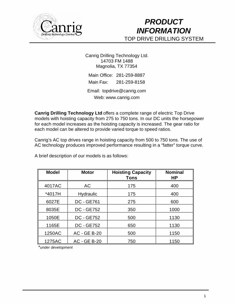
Canrig Drilling Technology Ltd offers a complete range of electric Top Drive models with hoisting capacity from 275 to 750 tons. In our DC units the horsepower for each model increases as the hoisting capacity is increased. The gear ratio for each model can be altered to provide varied torque to speed ratios. Canrig’s AC top drives range in hoisting capacity from 500 to 750 tons. The use of AC technology produces improved performance resulting in a “fatter” torque curve. A brief description of our models is as follows:
Model Motor Hoisting Capacity Tons
Nominal HP
4017AC AC 175 400
*4017H Hydraulic 175 400
6027E DC - GE761 275 600
8035E DC - GE752 350 1000
1050E DC - GE752 500 1130
1165E DC - GE752 650 1130
1250AC AC - GE B-20 500 1150
1275AC AC - GE B-20 750 1150 *under development

2
PRODUCT INFORMATION
FEATURES AND BENEFITS
Ø Features and Benefits of a Canrig Top Drive Drilling System
1. Integral Swivel • Eliminates fatigue failures associated with threaded connections.
2. Hydraulic Torque Boost • Continuous rotation of up to 5 RPM • Precise directional control
3. Industry Exclusive Floating Quill for Soft Stabbing and Thread Advance Compensation • Prevent thread damage during make-up and break-out.
4. Polymer Slide Guide Runners • Fewer components, significantly reducing the risk of falling parts. • Improved load distribution
5. Counter Balance Feature • Duplicates the dampening effect of the spring on a conventional hook.
6. Dual Lower Well Control Valves, One Manual and One Remote Actuated • Provides optimal well control
7. Remote Actuated Upper Well Control Valve • Improves well control options and acts as mud saver valve.
8. Local or Remote Blower Option • Operator selected-based on hazardous area requirements.
9. Wireline Guide System • Enables efficient wireline entry.
10. Direct Connection to Rigs Traveling Block • Reduces system height and weight by eliminating the block hook.
11. Disc Brake • Allows infinite positions for directional orientation. • Provides inertia braking.
12. AC or DC Electric Drive Motor • Allows operator to select configuration best suited to the application.
13. “Soft Torque” Vibration Control System Available • Reduces “slip-stick” thus improving drilling efficiency.
14. Remote Control of Pipe Handler Orientation and a Lock • Permits driller to maximize efficiency of pipe handling operations.
15. By-Directional Link Tilt Function • Permits overdrill thus allowing connection to be made with bit off
bottom. 16. Load Path Integrity – No Thread Connections in the Load Path
• Eliminates fatigue type failures associated with threaded connections.
3
PRODUCT INFORMATION
FEATURES AND BENEFITS
Motor
Dep
ende
nt o
n le
ngth
of
bloc
k
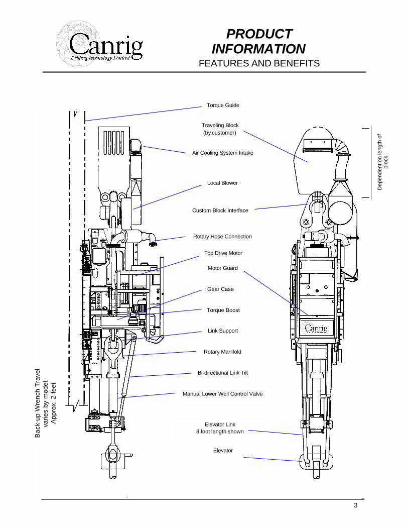
Traveling Block (by customer)
Air Cooling System Intake
Local Blower
Custom Block Interface
Rotary Hose Connection
Motor Guard
Gear Case
Torque Boost
Link Support
Rotary Manifold
Bi-directional Link Tilt
Manual Lower Well Control Valve
Elevator Link 8 foot length shown
Elevator
Torque Guide
Bac
k-up
Wre
nch
Tra
vel
varie
s by
mod
el.
App
rox.
2 fe
et
Top Drive Motor
4
PRODUCT INFORMATION THE TOP DRIVE UNIT
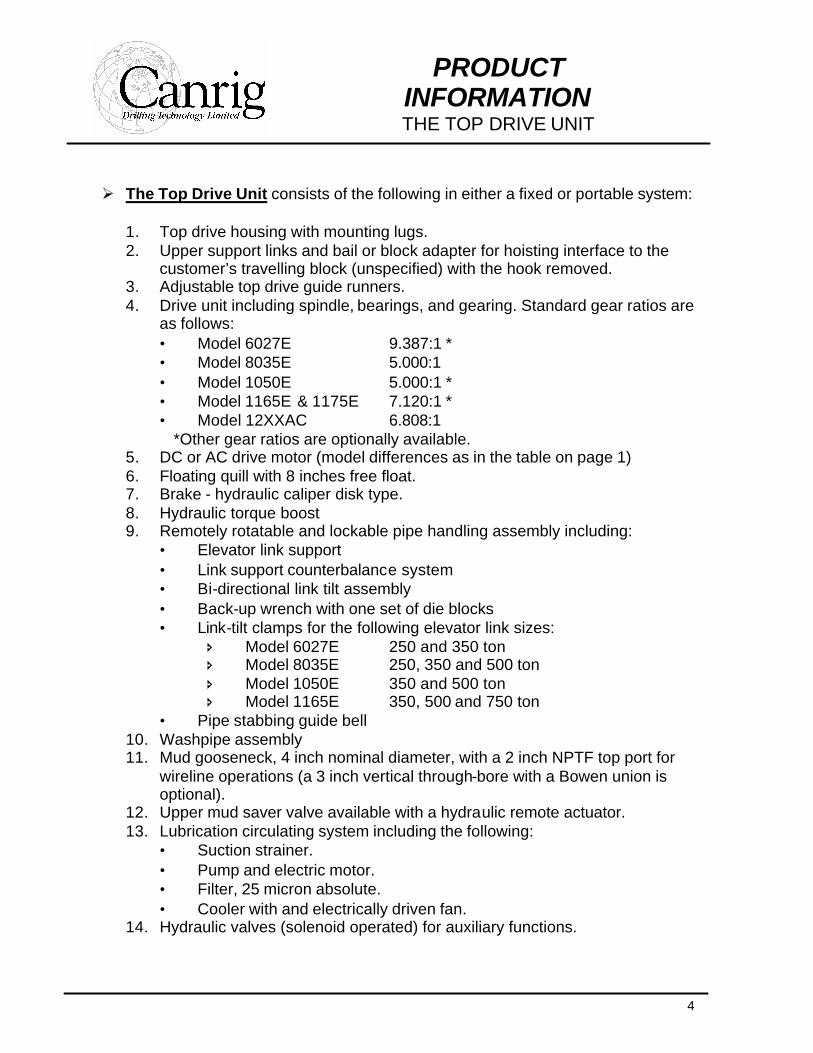
Ø The Top Drive Unit consists of the following in either a fixed or portable system:
1. Top drive housing with mounting lugs. 2. Upper support links and bail or block adapter for hoisting interface to the
customer’s travelling block (unspecified) with the hook removed. 3. Adjustable top drive guide runners. 4. Drive unit including spindle, bearings, and gearing. Standard gear ratios are
as follows: • Model 6027E 9.387:1 * • Model 8035E 5.000:1 • Model 1050E 5.000:1 * • Model 1165E & 1175E 7.120:1 * • Model 12XXAC 6.808:1
*Other gear ratios are optionally available. 5. DC or AC drive motor (model differences as in the table on page 1) 6. Floating quill with 8 inches free float. 7. Brake - hydraulic caliper disk type. 8. Hydraulic torque boost 9. Remotely rotatable and lockable pipe handling assembly including:
• Elevator link support • Link support counterbalance system • Bi-directional link tilt assembly • Back-up wrench with one set of die blocks • Link-tilt clamps for the following elevator link sizes:
î Model 6027E 250 and 350 ton î Model 8035E 250, 350 and 500 ton î Model 1050E 350 and 500 ton î Model 1165E 350, 500 and 750 ton
• Pipe stabbing guide bell 10. Washpipe assembly 11. Mud gooseneck, 4 inch nominal diameter, with a 2 inch NPTF top port for
wireline operations (a 3 inch vertical through-bore with a Bowen union is optional).
12. Upper mud saver valve available with a hydraulic remote actuator. 13. Lubrication circulating system including the following:
• Suction strainer. • Pump and electric motor. • Filter, 25 micron absolute. • Cooler with and electrically driven fan.
14. Hydraulic valves (solenoid operated) for auxiliary functions.
5
PRODUCT INFORMATION THE TOP DRIVE UNIT
15. Hydraulic piping, hose and fittings on the top drive unit. Diagnostic pressure test points are provided for all functions. Hose and tube fittings are the "ORS" type for premium sealing performance.
16. Instrumentation gauges and sensors including the following: • Hydraulic pressure and return gauges. • Lubrication pressure gauge. • Lubrication temperature gauge. • Lubrication alarm pressure switch. • Lubrication alarm temperature switch. • Air cooling alarm pressure switch. • RPM sensor.
17. Service connections for the kelly hose, hydraulics, DC power, electrical controls, and cooling air.
18. Lower well control valve (LWCV), manual operation, connections to match drill pipe, 10 000 psi WP is standard, with extended pin end for recut allowance. Quantity 2 valves furnished to allow for one running and one being re-cut.
19. Crossover sub between the quill and the LWCV 20. High-torque tool joint clamp for the LWCV connections. 21. Prepared, primed and painted (safety yellow). 22. Parts, maintenance and operating manuals, 4 copies 23. Conformance to API Specifications 7, 8C, RP14F, and RP500B. 24. Electrical equipment complies with the requirements of CSA and API 500B. 25. Adapter for connection of the mast sling line equalizer to the block adapter. 26. Drill collar handling subs for drilling and reaming drill collars, quantity 2 for
up to 7 inch collars and quantity 2 for up to 9 inch collars. 27. Top drive tool kit.
6
PRODUCT INFORMATION
DC TOP DRIVE MODEL 6027E
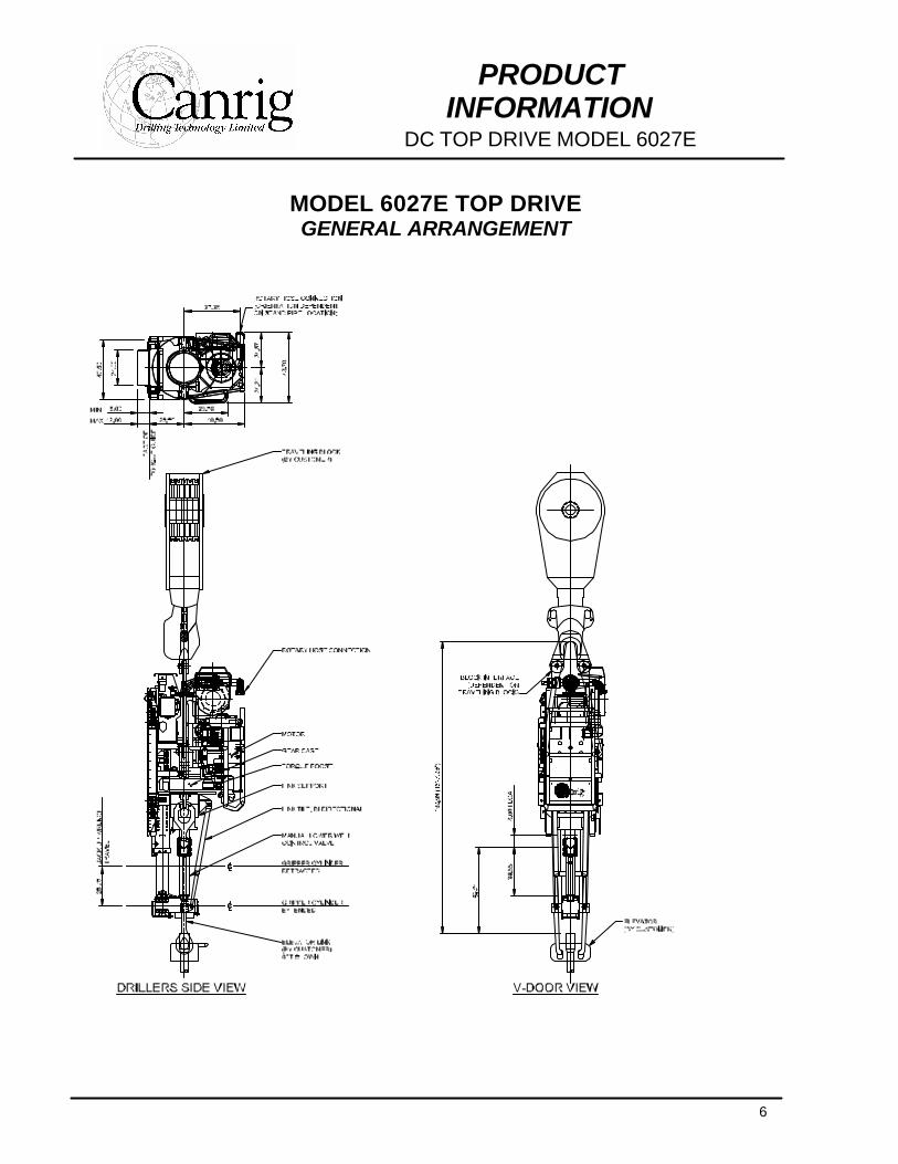
MODEL 6027E TOP DRIVE GENERAL ARRANGEMENT
7
PRODUCT INFORMATION
DC TOP DRIVE MODEL 6027E
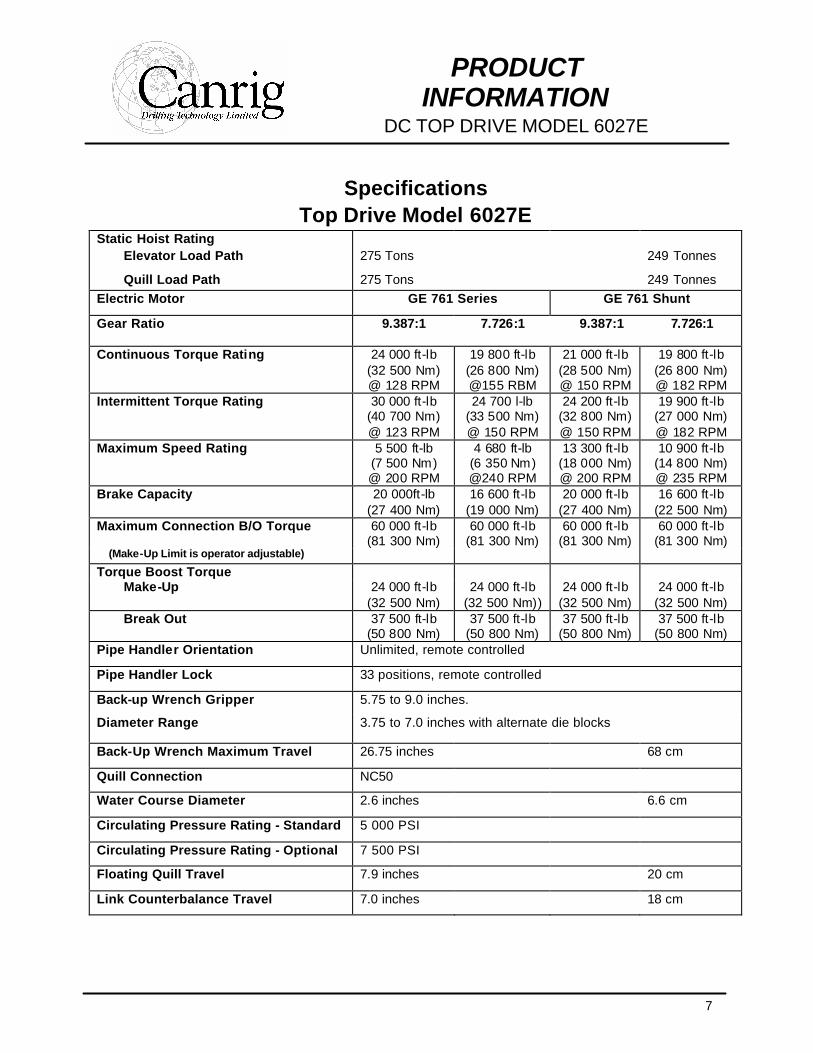
Specifications Top Drive Model 6027E
Static Hoist Rating Elevator Load Path 275 Tons 249 Tonnes
Quill Load Path 275 Tons 249 Tonnes Electric Motor GE 761 Series GE 761 Shunt
Gear Ratio 9.387:1
7.726:1 9.387:1 7.726:1
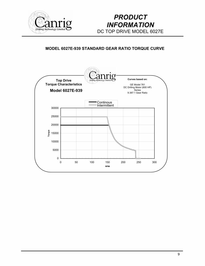
Continuous Torque Rating 24 000 ft-lb (32 500 Nm) @ 128 RPM
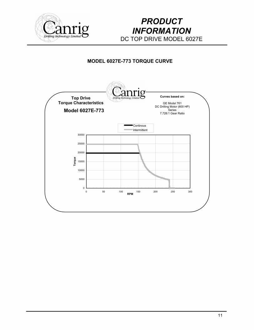
19 800 ft-lb (26 800 Nm) @155 RBM
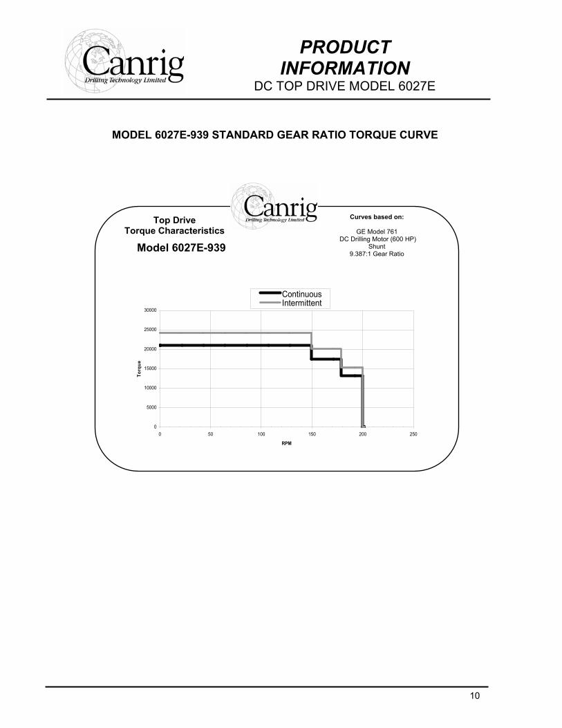
21 000 ft-lb (28 500 Nm) @ 150 RPM
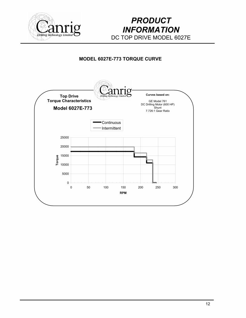
19 800 ft-lb (26 800 Nm) @ 182 RPM
Intermittent Torque Rating 30 000 ft-lb (40 700 Nm) @ 123 RPM
24 700 l-lb (33 500 Nm) @ 150 RPM
24 200 ft-lb (32 800 Nm) @ 150 RPM
19 900 ft-lb (27 000 Nm) @ 182 RPM
Maximum Speed Rating 5 500 ft-lb (7 500 Nm) @ 200 RPM
4 680 ft-lb (6 350 Nm) @240 RPM
13 300 ft-lb (18 000 Nm) @ 200 RPM
10 900 ft-lb (14 800 Nm) @ 235 RPM
Brake Capacity 20 000ft-lb (27 400 Nm)
16 600 ft-lb (19 000 Nm)
20 000 ft-lb (27 400 Nm)
16 600 ft-lb (22 500 Nm)
Maximum Connection B/O Torque 60 000 ft-lb (81 300 Nm)
60 000 ft-lb (81 300 Nm)
60 000 ft-lb (81 300 Nm)
60 000 ft-lb (81 300 Nm)
(Make-Up Limit is operator adjustable) Torque Boost Torque
Make-Up 24 000 ft-lb (32 500 Nm)
24 000 ft-lb (32 500 Nm))
24 000 ft-lb (32 500 Nm)
24 000 ft-lb (32 500 Nm)
Break Out 37 500 ft-lb (50 800 Nm)
37 500 ft-lb (50 800 Nm)
37 500 ft-lb (50 800 Nm)
37 500 ft-lb (50 800 Nm)
Pipe Handler Orientation Unlimited, remote controlled
Pipe Handler Lock 33 positions, remote controlled
Back-up Wrench Gripper 5.75 to 9.0 inches.
Diameter Range 3.75 to 7.0 inches with alternate die blocks
Back-Up Wrench Maximum Travel 26.75 inches 68 cm
Quill Connection NC50
Water Course Diameter 2.6 inches 6.6 cm
Circulating Pressure Rating - Standard 5 000 PSI
Circulating Pressure Rating - Optional 7 500 PSI
Floating Quill Travel 7.9 inches 20 cm
Link Counterbalance Travel 7.0 inches 18 cm
8
PRODUCT INFORMATION
DC TOP DRIVE MODEL 6027E
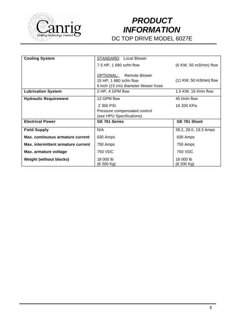
Cooling System STANDARD: Local Blower
7.5 HP, 1 680 scfm flow (6 KW, 50 m3/min) flow OPTIONAL: Remote Blower 15 HP, 1 680 scfm flow (11 KW, 50 m3/min) flow 6 inch (15 cm) diameter blower hose Lubrication System 2 HP, 4 GPM flow 1.5 KW, 15 l/min flow
Hydraulic Requirement 12 GPM flow 45 l/min flow
2 350 PSI 16 200 KPa Pressure compensated control (see HPU Specifications) Electrical Power GE 761 Series GE 761 Shunt
Field Supply N/A 39.2, 28.0, 19.3 Amps
Max. continuous armature current 630 Amps 630 Amps
Max. intermittent armature current 750 Amps 750 Amps
Max. armature voltage 750 VDC 750 VDC
Weight (without blocks) 18 000 lb (8 200 Kg)
18 000 lb (8 200 Kg)
9
PRODUCT INFORMATION
DC TOP DRIVE MODEL 6027E
MODEL 6027E-939 STANDARD GEAR RATIO TORQUE CURVE
Top Drive Torque Characteristics
Model 6027E-939
Curves based on:
GE Model 761 DC Drilling Motor (600 HP)
Series 9.387:1 Gear Ratio
0
5000
10000
15000
20000
25000
30000
0 50 100 150 200 250 300RPM
Torq
ue
ContinousIntermittent
10
PRODUCT INFORMATION
DC TOP DRIVE MODEL 6027E
MODEL 6027E-939 STANDARD GEAR RATIO TORQUE CURVE
Top Drive Torque Characteristics
Model 6027E-939
Curves based on:
GE Model 761 DC Drilling Motor (600 HP)
Shunt 9.387:1 Gear Ratio
0
5000
10000
15000
20000
25000
30000
0 50 100 150 200 250
RPM
Torq
ue
ContinuousIntermittent
11
PRODUCT INFORMATION
DC TOP DRIVE MODEL 6027E
MODEL 6027E-773 TORQUE CURVE
Top Drive Torque Characteristics
Model 6027E-773
Curves based on:
GE Model 761 DC Drilling Motor (600 HP)
Series 7.726:1 Gear Ratio
0
5000
10000
15000
20000
25000
30000
0 50 100 150 200 250 300RPM
Torq
ue
ContinousIntermittent
12
PRODUCT INFORMATION
DC TOP DRIVE MODEL 6027E
MODEL 6027E-773 TORQUE CURVE
Top Drive Torque Characteristics
Model 6027E-773
Curves based on:
GE Model 761 DC Drilling Motor (600 HP)
Shunt 7.726:1 Gear Ratio
0
5000
10000
15000
20000
25000
0 50 100 150 200 250 300
RPM
Torq
ue
ContinuousIntermittent
13
PRODUCT INFORMATION
DC TOP DRIVE MODEL 8035E
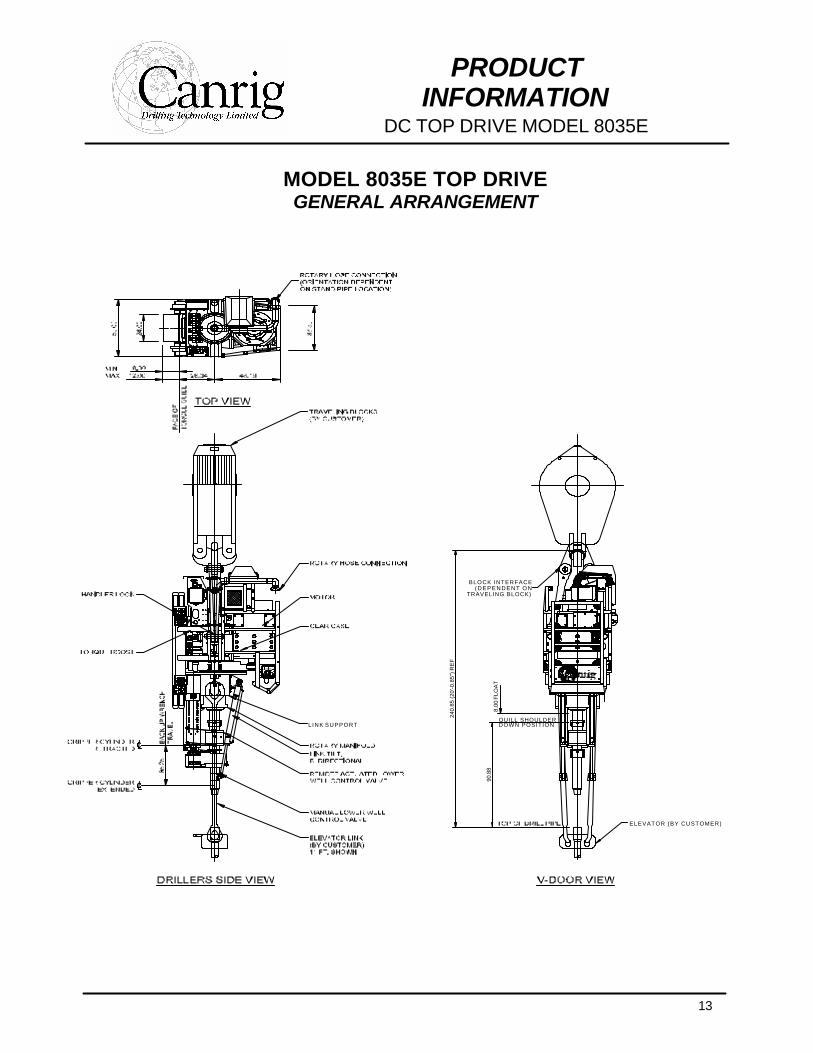
MODEL 8035E TOP DRIVE GENERAL ARRANGEMENT
TRAVELING BLOCK)(DEPENDENT ON
BLOCK INTERFACE
DOWN POSITIONQUILL SHOULDER
LINK SUPPORT
D R I L L I N G S Y S T E MTOP DRIVE
240.
85 (2
0'-0
.85"
) RE
F
8.00
FLO
AT
90.8
8
ELEVATOR (BY CUSTOMER)
14
PRODUCT INFORMATION
DC TOP DRIVE MODEL 8035E
All dimensions in inches.
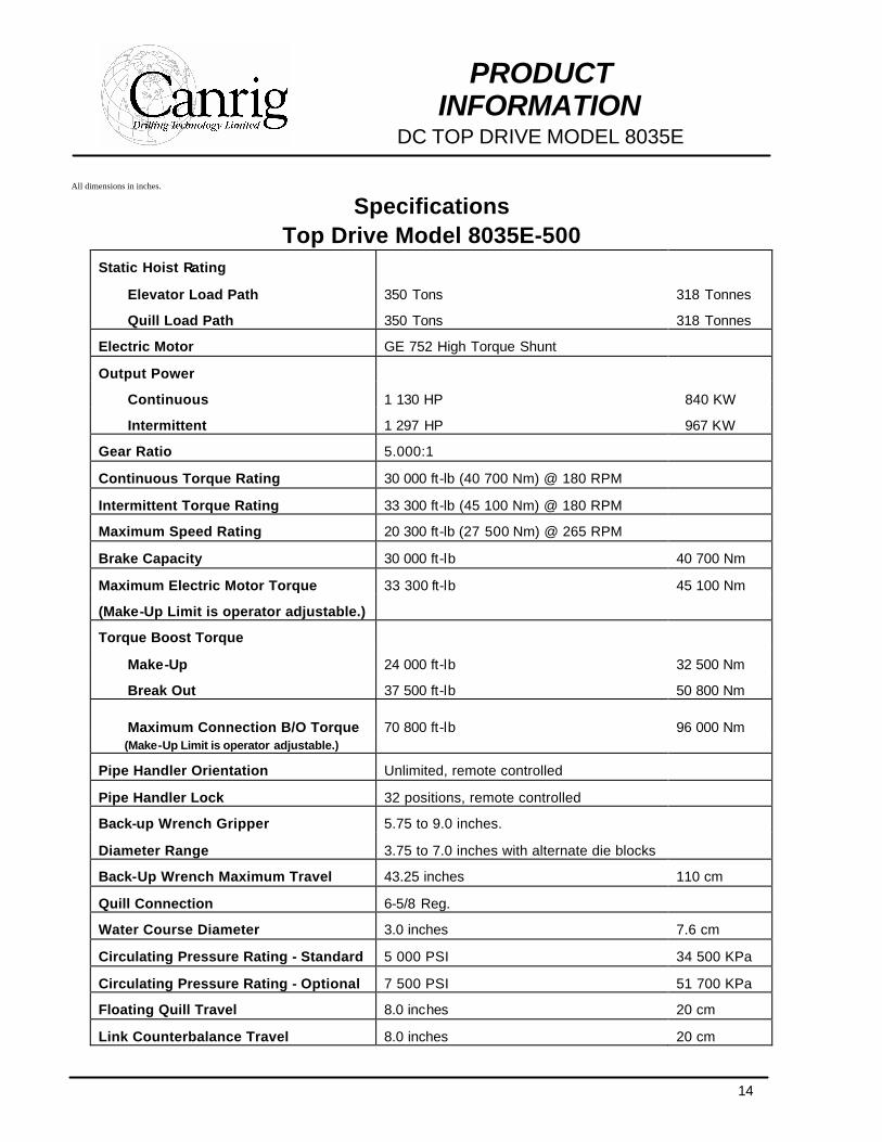
Specifications Top Drive Model 8035E-500
Static Hoist Rating
Elevator Load Path 350 Tons 318 Tonnes
Quill Load Path 350 Tons 318 Tonnes
Electric Motor GE 752 High Torque Shunt
Output Power
Continuous 1 130 HP 840 KW
Intermittent 1 297 HP 967 KW
Gear Ratio 5.000:1
Continuous Torque Rating 30 000 ft-lb (40 700 Nm) @ 180 RPM
Intermittent Torque Rating 33 300 ft-lb (45 100 Nm) @ 180 RPM
Maximum Speed Rating 20 300 ft-lb (27 500 Nm) @ 265 RPM
Brake Capacity 30 000 ft-lb 40 700 Nm
Maximum Electric Motor Torque 33 300 ft-lb 45 100 Nm
(Make-Up Limit is operator adjustable.)
Torque Boost Torque
Make-Up 24 000 ft-lb 32 500 Nm
Break Out 37 500 ft-lb 50 800 Nm
Maximum Connection B/O Torque 70 800 ft-lb 96 000 Nm (Make-Up Limit is operator adjustable.)
Pipe Handler Orientation Unlimited, remote controlled
Pipe Handler Lock 32 positions, remote controlled
Back-up Wrench Gripper 5.75 to 9.0 inches.
Diameter Range 3.75 to 7.0 inches with alternate die blocks
Back-Up Wrench Maximum Travel 43.25 inches 110 cm
Quill Connection 6-5/8 Reg.
Water Course Diameter 3.0 inches 7.6 cm
Circulating Pressure Rating - Standard 5 000 PSI 34 500 KPa
Circulating Pressure Rating - Optional 7 500 PSI 51 700 KPa
Floating Quill Travel 8.0 inches 20 cm
Link Counterbalance Travel 8.0 inches 20 cm
15
PRODUCT INFORMATION
DC TOP DRIVE MODEL 8035E
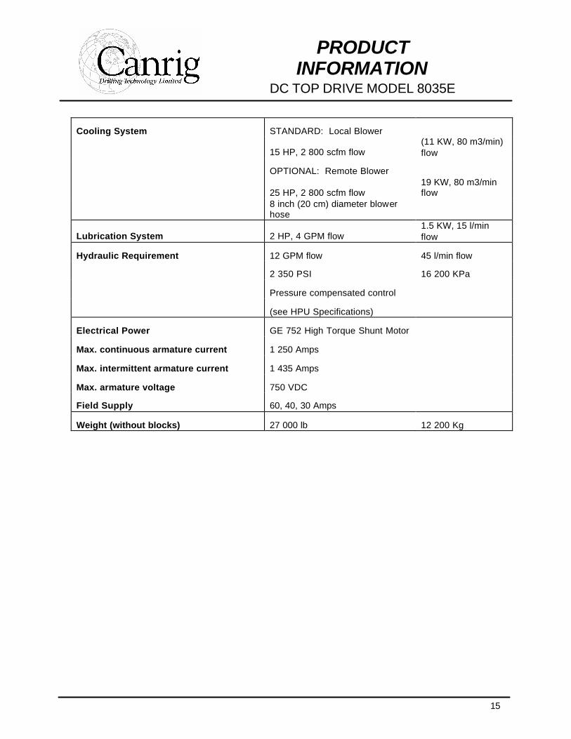
Cooling System STANDARD: Local Blower
15 HP, 2 800 scfm flow (11 KW, 80 m3/min) flow
OPTIONAL: Remote Blower
25 HP, 2 800 scfm flow 19 KW, 80 m3/min flow
8 inch (20 cm) diameter blower hose
Lubrication System 2 HP, 4 GPM flow 1.5 KW, 15 l/min flow
Hydraulic Requirement 12 GPM flow 45 l/min flow
2 350 PSI 16 200 KPa
Pressure compensated control
(see HPU Specifications)
Electrical Power GE 752 High Torque Shunt Motor
Max. continuous armature current 1 250 Amps
Max. intermittent armature current 1 435 Amps
Max. armature voltage 750 VDC
Field Supply 60, 40, 30 Amps
Weight (without blocks) 27 000 lb 12 200 Kg
16
PRODUCT INFORMATION
DC TOP DRIVE MODEL 8035E
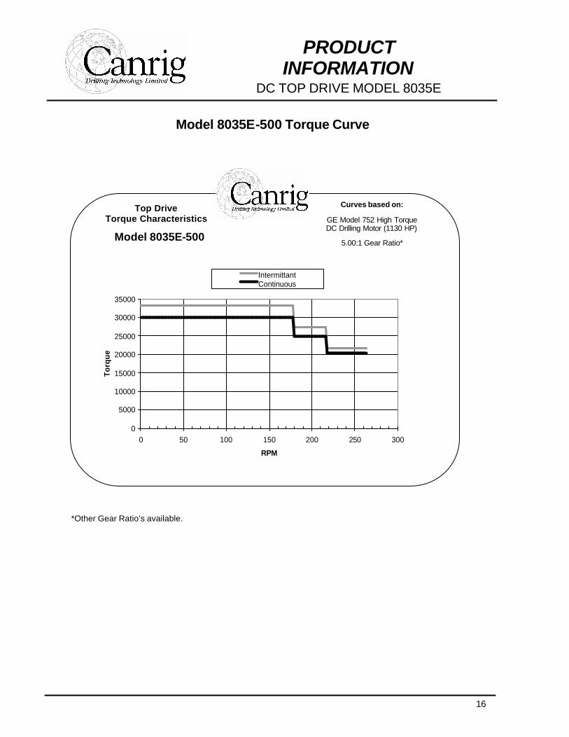
Model 8035E-500 Torque Curve *Other Gear Ratio’s available.
Top Drive Torque Characteristics
Model 8035E-500
Curves based on:
GE Model 752 High Torque DC Drilling Motor (1130 HP)
5.00:1 Gear Ratio*
0
5000
10000
15000
20000
25000
30000
35000
0 50 100 150 200 250 300
RPM
To
rqu
e
IntermittantContinuous
17
PRODUCT INFORMATION
DC TOP DRIVE MODEL 1050E
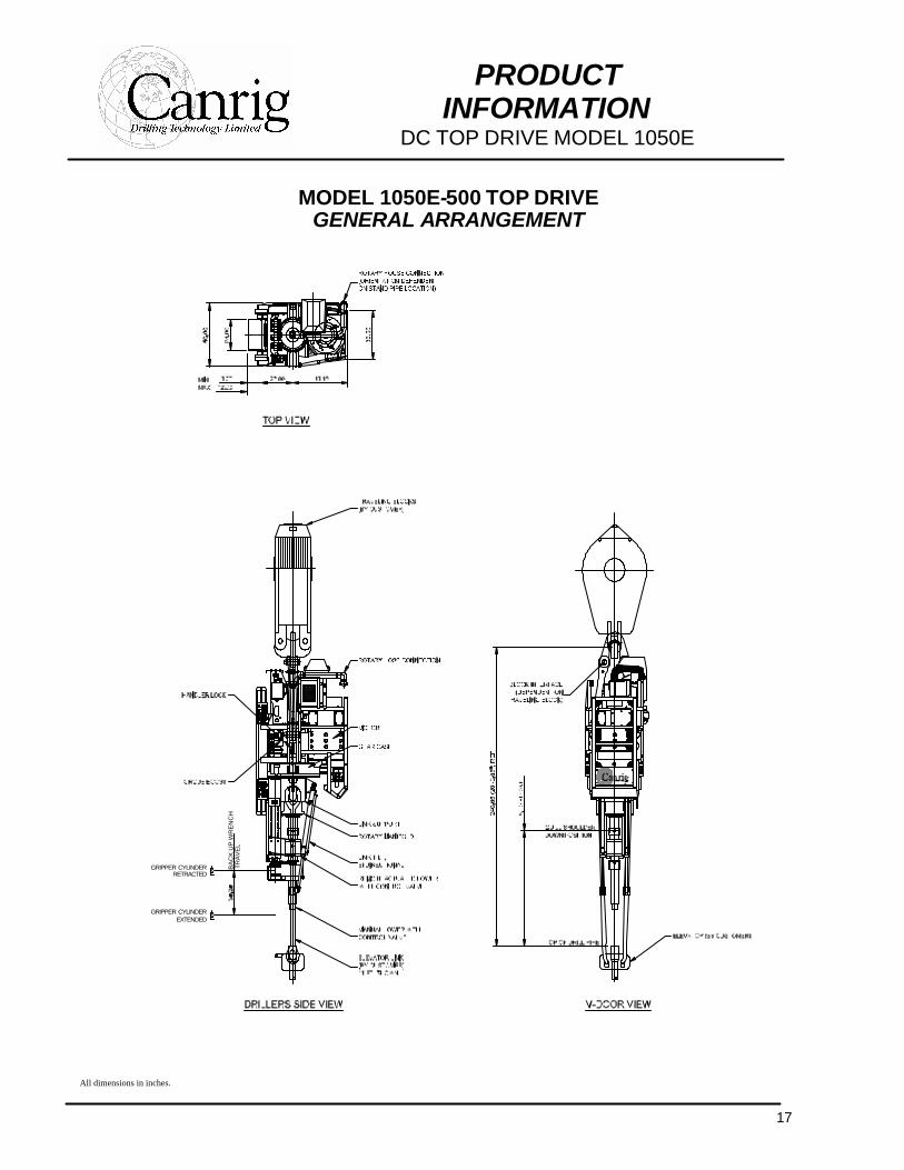
MODEL 1050E-500 TOP DRIVE GENERAL ARRANGEMENT
GRIPPER CYLINDEREXTENDED
GRIPPER CYLINDERRETRACTED
BA
CK
UP
WR
EN
CH
TR
AV
EL
TOP DRIVEDRILLING SYSTEM
All dimensions in inches.
18
PRODUCT INFORMATION
DC TOP DRIVE MODEL 1050E
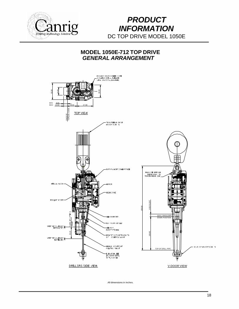
MODEL 1050E-712 TOP DRIVE GENERAL ARRANGEMENT
35
.25
TO
RQ
UE
GU
IDE
FA
CE
OF
29.0012.008.00
MAXMIN
24.0
0
50.0
0
47.88
38.5
0
V-DOOR VIEW
DOWN POSITION
TOP OF DRILL PIPE
QUILL SHOULDER
100.
82
253.
92
8.00
FLO
AT
All dimensions in inches.
19
PRODUCT INFORMATION
DC TOP DRIVE MODEL 1050E
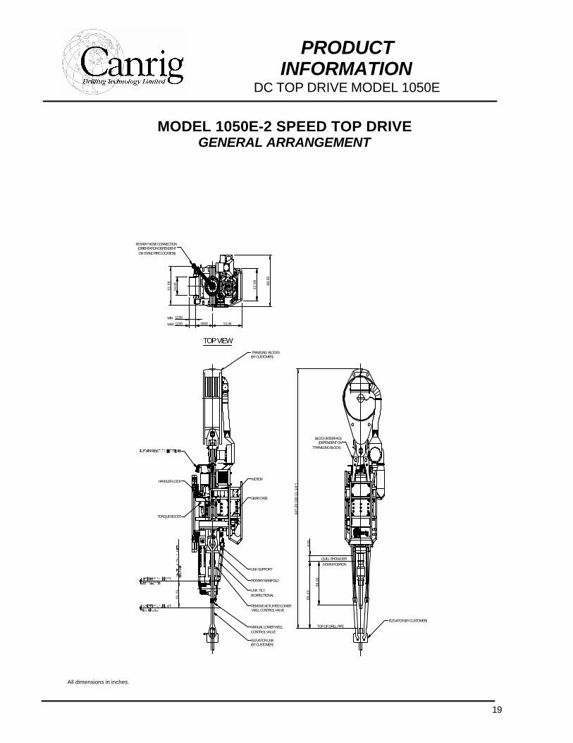
MODEL 1050E-2 SPEED TOP DRIVE GENERAL ARRANGEMENT
All dimensions in inches.
BLOCK INTERFACE(DEPENDENT ON
TTRAVELING BLOCK)
347.
29 (2
8'-1
1 1/
4")
8.00
58.0
0
89.2
4
35.2
5
TORQUE BOOST
WELL CONTROL VALVEREMOVE ACTUATED LOWER
MANUAL LOWER WELL
LINK TILT,
CONTROL VALVE
(BY CUSTOMER)ELEVATOR LINK
BI DIRECTIONAL
LINK SUPPORT
ROTARY MANIFOLD
TOP OF DRILL PIPE
DOWN POSITIONQUILL SHOULDER
TOP VIEW
51.44
HANDLER LOCK
51.5
9
ROTARY HOSE CONNECTION(ORIENTATION DEPENDENTON STAND PIPE LOCATION)
12.00
12.00
24.0
0
MAX
MIN29.00
GEAR CASE
MOTOR
(BY CUSTOMER)TRAVELING BLOCKS
68.9
5
42.6
8
ELEVATOR (BY CUSTOMER)
20
PRODUCT INFORMATION
DC TOP DRIVE MODEL 1050E
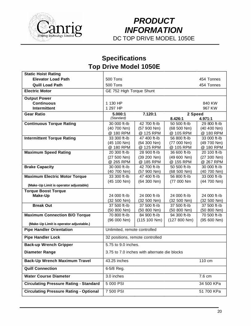
Specifications Top Drive Model 1050E
Static Hoist Rating Elevator Load Path 500 Tons 454 Tonnes Quill Load Path 500 Tons 454 Tonnes Electric Motor GE 752 High Torque Shunt
Output Power Continuous 1 130 HP 840 KW Intermittent 1 297 HP 967 KW
Gear Ratio 5.000:1 (Standard)
7.120:1 2 Speed 8.426:1 4.971:1
Continuous Torque Rating 30 000 ft-lb (40 700 Nm) @ 180 RPM
42 700 ft-lb (57 900 Nm) @ 125 RPM
50 500 ft-lb (68 500 Nm) @ 105 RPM
29 800 ft-lb (40 400 Nm) @ 180 RPM
Intermittent Torque Rating 33 300 ft-lb (45 100 Nm) @ 180 RPM
47 400 ft-lb (64 300 Nm) @ 125 RPM
56 800 ft-lb (77 000 Nm) @ 105 RPM
33 000 ft-lb (49 700 Nm) @ 180 RPM
Maximum Speed Rating 20 300 ft-lb (27 500 Nm) @ 265 RPM
28 900 ft-lb (39 200 Nm) @ 185 RPM
36 600 ft-lb (49 600 Nm) @ 155 RPM
20 100 ft-lb (27 300 Nm) @ 267 RPM
Brake Capacity 30 000 ft-lb (40 700 Nm)
42 700 ft-lb (57 900 Nm)
50 500 ft-lb (68 500 Nm)
30 000 ft-lb (40 700 Nm)
Maximum Electric Motor Torque 33 300 ft-lb (45 100 Nm)
47 400 ft-lb (64 300 Nm)
56 800 ft-lb (77 000 Nm
33 000 ft-lb (44 700 Nm)
(Make-Up Limit is operator adjustable) Torque Boost Torque
Make-Up 24 000 ft-lb (32 500 Nm)
24 000 ft-lb (32 500 Nm)
24 000 ft-lb (32 500 Nm)
24 000 ft-lb (32 500 Nm)
Break Out 37 500 ft-lb (50 800 Nm)
37 500 ft-lb (50 800 Nm)
37 500 ft-lb (50 800 Nm)
37 500 ft-lb (50 800 Nm)
Maximum Connection B/O Torque 70 800 ft-lb (96 000 Nm)
84 900 ft-lb (115 100 Nm)
94 300 ft-lb (127 800 Nm)
70 500 ft-lb (95 600 Nm)
(Make-Up Limit is operator adjustable.) Pipe Handler Orientation Unlimited, remote controlled
Pipe Handler Lock 32 positions, remote controlled
Back-up Wrench Gripper 5.75 to 9.0 inches.
Diameter Range 3.75 to 7.0 inches with alternate die blocks
Back-Up Wrench Maximum Travel 43.25 inches 110 cm
Quill Connection 6-5/8 Reg.
Water Course Diameter 3.0 inches 7.6 cm
Circulating Pressure Rating - Standard 5 000 PSI 34 500 KPa
Circulating Pressure Rating - Optional 7 500 PSI 51 700 KPa
21
PRODUCT INFORMATION
DC TOP DRIVE MODEL 1050E
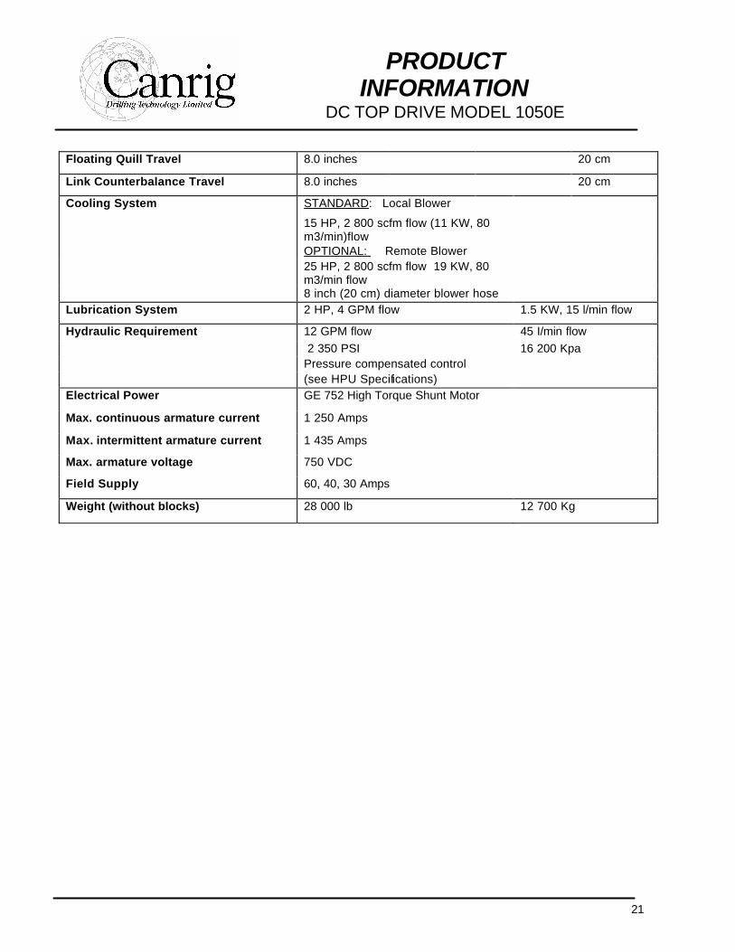
Floating Quill Travel 8.0 inches 20 cm
Link Counterbalance Travel 8.0 inches 20 cm
Cooling System STANDARD: Local Blower
15 HP, 2 800 scfm flow (11 KW, 80 m3/min)flow
OPTIONAL: Remote Blower 25 HP, 2 800 scfm flow 19 KW, 80
m3/min flow
8 inch (20 cm) diameter blower hose Lubrication System 2 HP, 4 GPM flow 1.5 KW, 15 l/min flow
Hydraulic Requirement 12 GPM flow 45 I/min flow 2 350 PSI 16 200 Kpa Pressure compensated control (see HPU Specifications) Electrical Power GE 752 High Torque Shunt Motor
Max. continuous armature current 1 250 Amps
Max. intermittent armature current 1 435 Amps
Max. armature voltage 750 VDC
Field Supply 60, 40, 30 Amps
Weight (without blocks) 28 000 lb 12 700 Kg
22
PRODUCT INFORMATION
DC TOP DRIVE MODEL 1050E
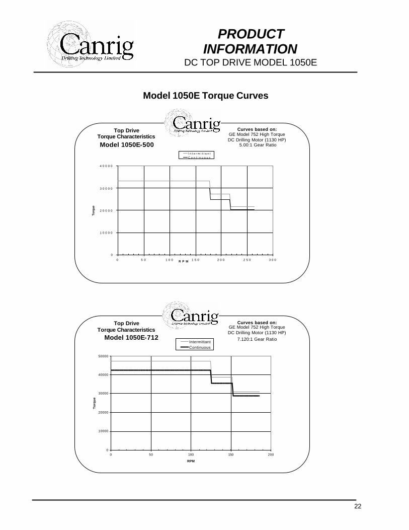
Model 1050E Torque Curves
Top Drive Torque Characteristics
Model 1050E-500
Curves based on: GE Model 752 High Torque DC Drilling Motor (1130 HP)
5.00:1 Gear Ratio
0
1 0 0 0 0
2 0 0 0 0
3 0 0 0 0
4 0 0 0 0
0 5 0 1 0 0 1 5 0 2 0 0 2 5 0 3 0 0R P M
Torq
ue
I n t e r m i t t a n tC o n t i n u o u s
Top Drive Torque Characteristics
Model 1050E-712
Curves based on: GE Model 752 High Torque DC Drilling Motor (1130 HP)
7.120:1 Gear Ratio
0
10000
20000
30000
40000
50000
0 50 100 150 200
RPM
To
rqu
e
IntermittantContinuous
23
PRODUCT INFORMATION
DC TOP DRIVE MODEL 1050E
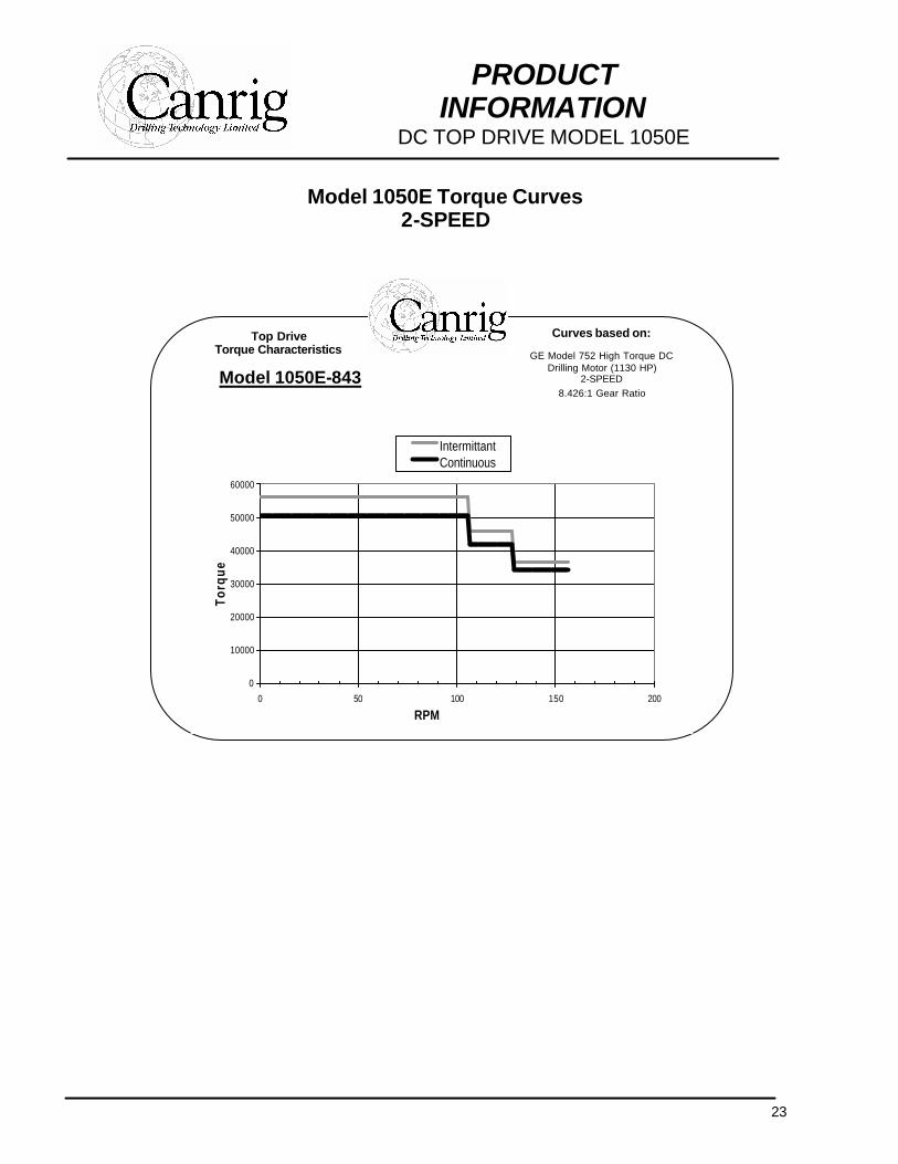
Model 1050E Torque Curves 2-SPEED
Top Drive Torque Characteristics
Model 1050E-843
Curves based on:
GE Model 752 High Torque DC Drilling Motor (1130 HP)
2-SPEED 8.426:1 Gear Ratio
0
10000
20000
30000
40000
50000
60000
0 50 100 150 200
RPM
Torq
ue
IntermittantContinuous

24
PRODUCT INFORMATION
DC TOP DRIVE MODEL 1050E
Model 1050E Torque Curves 2-SPEED
Top Drive Torque Characteristics
Model 1050E-497
Curves based on:
GE Model 752 High Torque DC Drilling Motor (1130 HP)
2-SPEED 4.971:1 Gear Ratio
0
10000
20000
30000
40000
0 50 100 150 200 250 300RPM
Torq
ue
IntermittantContinuous
25
PRODUCT INFORMATION
DC TOP DRIVE MODEL 1165E
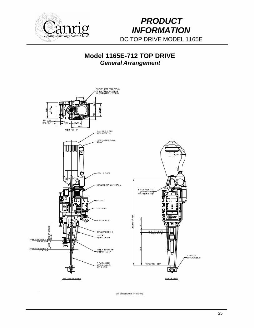
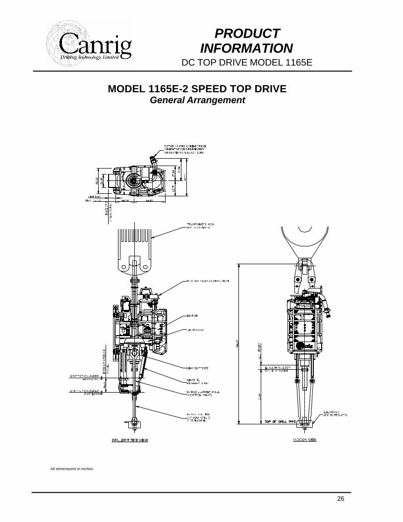
Model 1165E-712 TOP DRIVE General Arrangement
AAll dimensions in inches. All
All dimensions in inches.
26
PRODUCT INFORMATION
DC TOP DRIVE MODEL 1165E
MODEL 1165E-2 SPEED TOP DRIVE General Arrangement
All dimensions in inches.
27
PRODUCT INFORMATION
DC TOP DRIVE MODEL 1165E
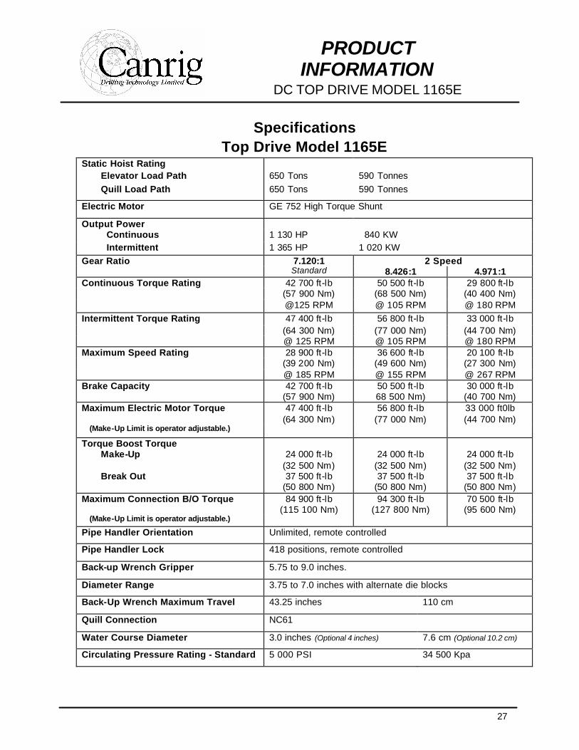
Specifications Top Drive Model 1165E
Static Hoist Rating Elevator Load Path 650 Tons 590 Tonnes Quill Load Path 650 Tons 590 Tonnes
Electric Motor GE 752 High Torque Shunt
Output Power Continuous 1 130 HP 840 KW Intermittent 1 365 HP 1 020 KW
Gear Ratio 7.120:1 2 Speed Standard 8.426:1 4.971:1 Continuous Torque Rating 42 700 ft-lb 50 500 ft-lb 29 800 ft-lb (57 900 Nm) (68 500 Nm) (40 400 Nm) @125 RPM @ 105 RPM @ 180 RPM Intermittent Torque Rating 47 400 ft-lb 56 800 ft-lb 33 000 ft-lb (64 300 Nm) (77 000 Nm) (44 700 Nm) @ 125 RPM @ 105 RPM @ 180 RPM Maximum Speed Rating 28 900 ft-lb 36 600 ft-lb 20 100 ft-lb (39 200 Nm) (49 600 Nm) (27 300 Nm) @ 185 RPM @ 155 RPM @ 267 RPM Brake Capacity 42 700 ft-lb
(57 900 Nm) 50 500 ft-lb 68 500 Nm)
30 000 ft-lb (40 700 Nm)
Maximum Electric Motor Torque 47 400 ft-lb (64 300 Nm)
56 800 ft-lb (77 000 Nm)
33 000 ft0lb (44 700 Nm)
(Make-Up Limit is operator adjustable.) Torque Boost Torque
Make-Up 24 000 ft-lb (32 500 Nm)
24 000 ft-lb (32 500 Nm)
24 000 ft-lb (32 500 Nm)
Break Out 37 500 ft-lb (50 800 Nm)
37 500 ft-lb (50 800 Nm)
37 500 ft-lb (50 800 Nm)
Maximum Connection B/O Torque 84 900 ft-lb (115 100 Nm)
94 300 ft-lb (127 800 Nm)
70 500 ft-lb (95 600 Nm)
(Make-Up Limit is operator adjustable.) Pipe Handler Orientation Unlimited, remote controlled
Pipe Handler Lock 418 positions, remote controlled
Back-up Wrench Gripper 5.75 to 9.0 inches.
Diameter Range 3.75 to 7.0 inches with alternate die blocks
Back-Up Wrench Maximum Travel 43.25 inches 110 cm
Quill Connection NC61
Water Course Diameter 3.0 inches (Optional 4 inches) 7.6 cm (Optional 10.2 cm)
Circulating Pressure Rating - Standard 5 000 PSI 34 500 Kpa
28
PRODUCT INFORMATION
DC TOP DRIVE MODEL 1165E
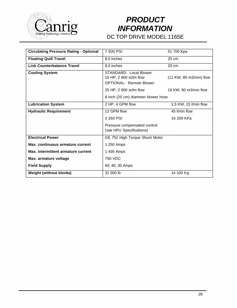
Circulating Pressure Rating - Optional 7 500 PSI 51 700 Kpa
Floating Quill Travel 8.0 inches 20 cm
Link Counterbalance Travel 8.0 inches 20 cm
Cooling System STANDARD: Local Blower 15 HP, 2 800 scfm flow (11 KW, 80 m3/min) flow OPTIONAL: Remote Blower
25 HP, 2 800 scfm flow 19 KW, 80 m3/min flow
8 inch (20 cm) diameter blower hose
Lubrication System 2 HP, 4 GPM flow 1.5 KW, 15 l/min flow
Hydraulic Requirement 12 GPM flow 45 l/min flow
2 350 PSI 16 200 KPa
Pressure compensated control (see HPU Specifications)
Electrical Power GE 752 High Torque Shunt Motor
Max. continuous armature current 1 250 Amps
Max. intermittent armature current 1 435 Amps
Max. armature voltage 750 VDC
Field Supply 60, 40, 30 Amps
Weight (without blocks) 31 000 lb 14 100 Kg
29
PRODUCT INFORMATION
DC TOP DRIVE MODEL 1165E
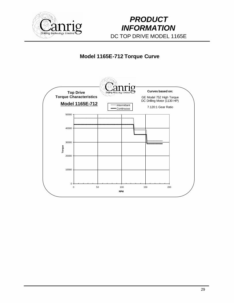
Model 1165E-712 Torque Curve
Top Drive Torque Characteristics
Model 1165E-712
Curves based on:
GE Model 752 High Torque DC Drilling Motor (1130 HP)
7.120:1 Gear Ratio
0
10000
20000
30000
40000
50000
0 50 100 150 200
RPM
To
rqu
e
IntermittantContinuous
30
PRODUCT INFORMATION
DC TOP DRIVE MODEL 1165E
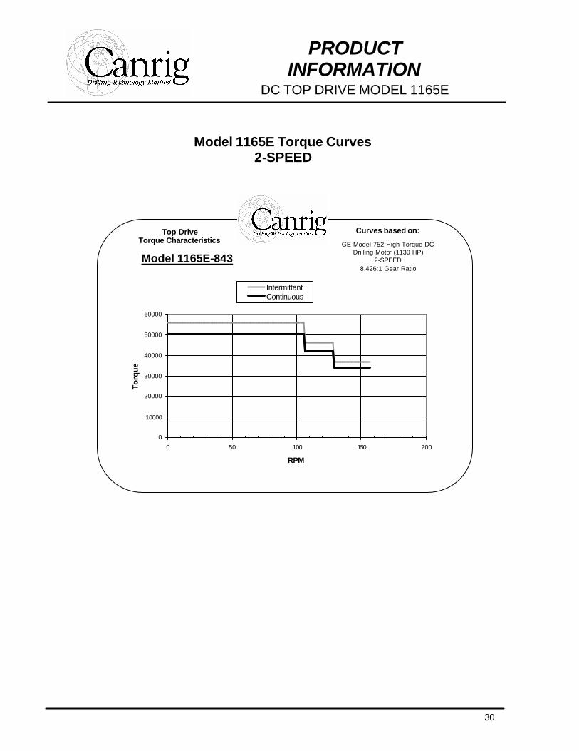
Model 1165E Torque Curves
2-SPEED
Top Drive Torque Characteristics
Model 1165E-843
Curves based on:
GE Model 752 High Torque DC Drilling Motor (1130 HP)
2-SPEED 8.426:1 Gear Ratio
0
10000
20000
30000
40000
50000
60000
0 50 100 150 200
RPM
To
rqu
e
IntermittantContinuous
31
PRODUCT INFORMATION
DC TOP DRIVE MODEL 1165E
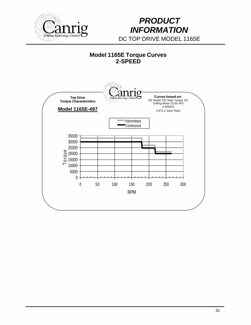
Model 1165E Torque Curves 2-SPEED
Top Drive Torque Characteristics
Model 1165E-497
Curves based on: GE Model 752 High Torque DC
Drilling Motor (1130 HP) 2-SPEED
4.971:1 Gear Ratio
05000
100001500020000250003000035000
0 50 100 150 200 250 300
RPM
Torq
ue
IntermittantContinuous
32
PRODUCT INFORMATION
AC TOP DRIVE MODELS
AC Technology Since the advantages of using top drives are well documented, the decision for most operators is whether to use DC or AC technology. Both have advantages that warrant consideration depending on application. The primary benefit of AC top drives is a significant better power factor. AC motors also have a better speed range and can be run at 200% of base speed and above. The horsepower characteristics of an AC motor are far superior to the DC equivalent. DC motors can maintain maximum horsepower at only one speed while AC motors maintain fill horsepower from base speed to approximately 150% of base speed. Other advantages to our AC Top Drive Drilling Systems are:
• Can stall motor for an indefinite period, with zero to maximum torque applied. • Enclosed, EExe or TEFC motor possible. This would eliminate the blower
hose (a rather cumbersome, but necessary feature on the DC motor). • Less maintenance due to lack of brushes. With a TEFC motor, this becomes
double important, considering that no dirt or moisture will be entering the motor and its windings.
• By utilizing a 12 pulse front-end variable frequency drive, substantial reduction in harmonics to the point where it will meet and exceed requirements of IEEE 581 standards, can be achieved. This feature becomes valuable if drilling power is obtained from Hiline Utility distribution.
• Our innovative modular design of the drive also allows for plug and play repair and maintenance.
• New technology. Utilization of latest components and engineering know-how.
33
PRODUCT INFORMATION
AC TOP DRIVE MODELS
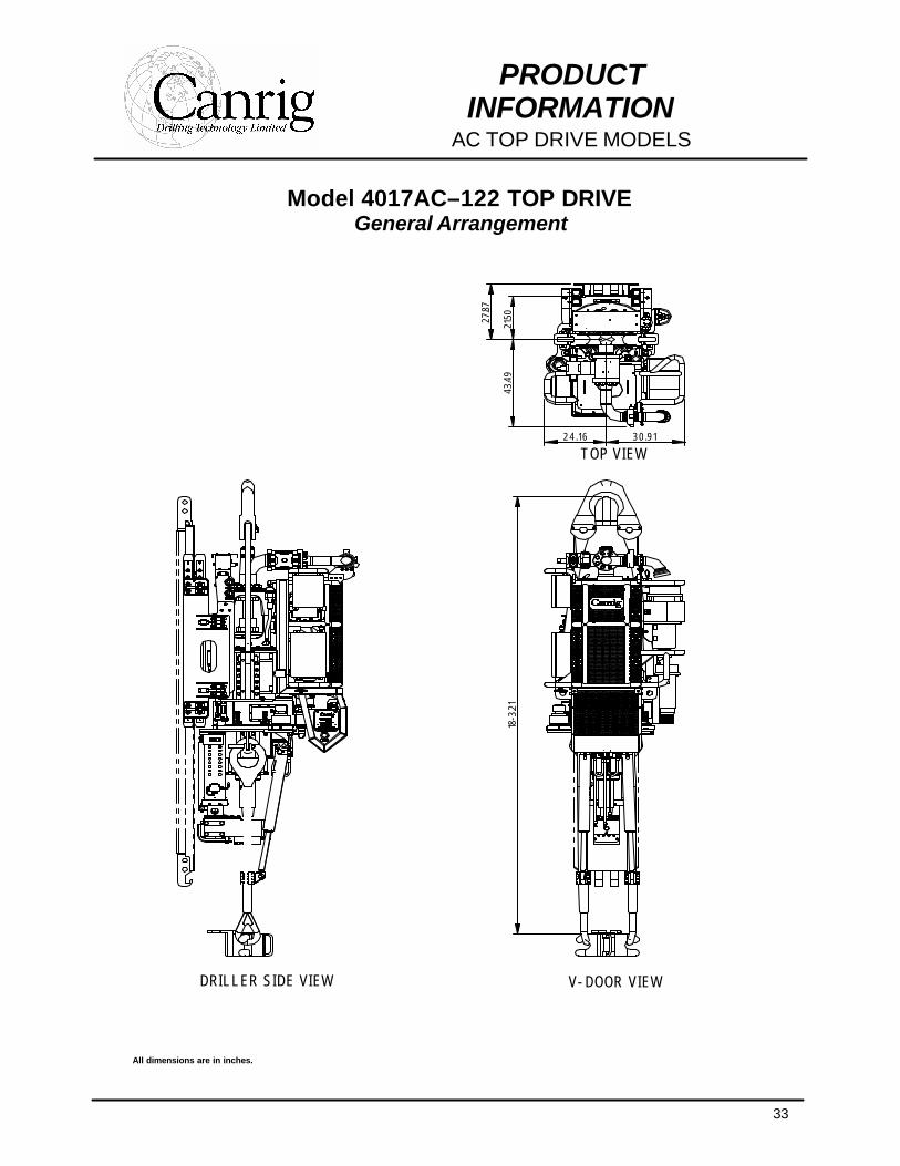
Model 4017AC–122 TOP DRIVE General Arrangement
All dimensions are in inches.
V-DOOR V I EW
TOP V I EW
DR ILLER S IDE V I EW
43.4
918
-3.2
1
24 . 16 30 .91
21.5027
.87
34
PRODUCT INFORMATION
AC TOP DRIVE MODELS
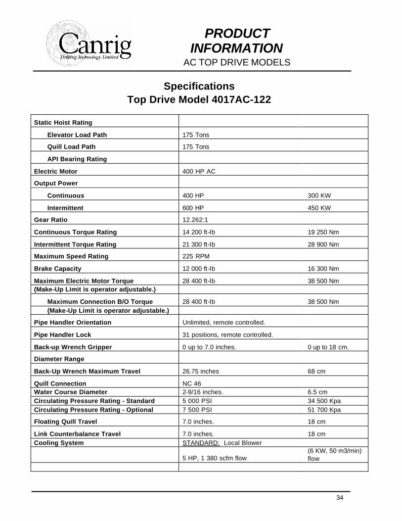
Specifications Top Drive Model 4017AC-122
Static Hoist Rating
Elevator Load Path 175 Tons
Quill Load Path 175 Tons
API Bearing Rating
Electric Motor 400 HP AC
Output Power
Continuous 400 HP 300 KW
Intermittent 600 HP 450 KW
Gear Ratio 12.262:1
Continuous Torque Rating 14 200 ft-lb 19 250 Nm
Intermittent Torque Rating 21 300 ft-lb 28 900 Nm
Maximum Speed Rating 225 RPM
Brake Capacity 12 000 ft-lb 16 300 Nm
Maximum Electric Motor Torque 28 400 ft-lb 38 500 Nm (Make-Up Limit is operator adjustable.)
Maximum Connection B/O Torque 28 400 ft-lb 38 500 Nm (Make-Up Limit is operator adjustable.)
Pipe Handler Orientation Unlimited, remote controlled.
Pipe Handler Lock 31 positions, remote controlled.
Back-up Wrench Gripper 0 up to 7.0 inches. 0 up to 18 cm.
Diameter Range
Back-Up Wrench Maximum Travel 26.75 inches 68 cm
Quill Connection NC 46 Water Course Diameter 2-9/16 inches. 6.5 cm Circulating Pressure Rating - Standard 5 000 PSI 34 500 Kpa Circulating Pressure Rating - Optional 7 500 PSI 51 700 Kpa
Floating Quill Travel 7.0 inches. 18 cm
Link Counterbalance Travel 7.0 inches. 18 cm Cooling System STANDARD: Local Blower
5 HP, 1 380 scfm flow (6 KW, 50 m3/min) flow
35
PRODUCT INFORMATION
AC TOP DRIVE MODELS
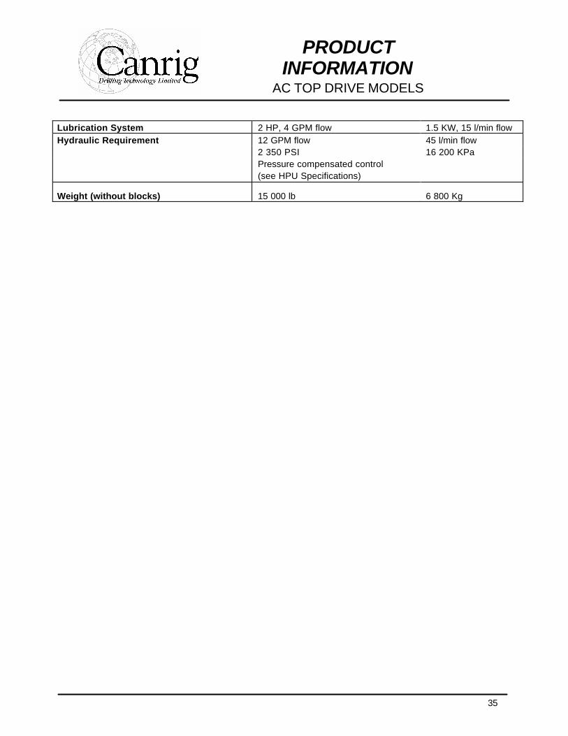
Lubrication System 2 HP, 4 GPM flow 1.5 KW, 15 l/min flow Hydraulic Requirement 12 GPM flow 45 l/min flow 2 350 PSI 16 200 KPa Pressure compensated control (see HPU Specifications)
Weight (without blocks) 15 000 lb 6 800 Kg
36
PRODUCT INFORMATION
AC TOP DRIVE MODELS
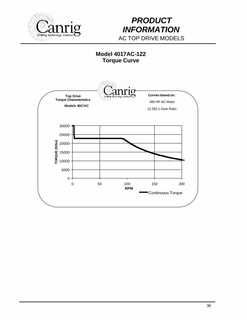
Model 4017AC-122 Torque Curve
Top Drive Torque Characteristics
Models 4017AC
Curves based on:
400 HP AC Motor
12.262:1 Gear Ratio
0
5000
10000
15000
20000
25000
30000
0 50 100 150 200RPM
TOR
QU
E (f
t/lbs
)
Continuous Torque
37
PRODUCT INFORMATION
AC TOP DRIVE MODELS
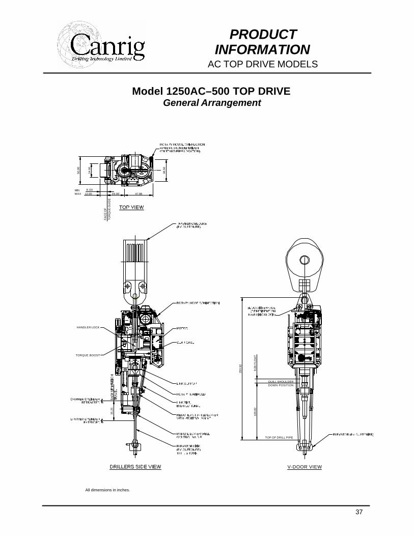
Model 1250AC–500 TOP DRIVE General Arrangement
All dimensions in inches.
35.2
5
TORQUE BOOST
HANDLER LOCK
TO
RQ
UE
GU
IDE
FA
CE
OF
29.0012.008.00
MAXMIN
24.0
0
50.0
0
47.88
38.5
0
V-DOOR VIEW
DOWN POSITION
TOP OF DRILL PIPE
QUILL SHOULDER
100.
82
253.
92
8.00
FLO
AT
38
PRODUCT INFORMATION
AC TOP DRIVE MODELS
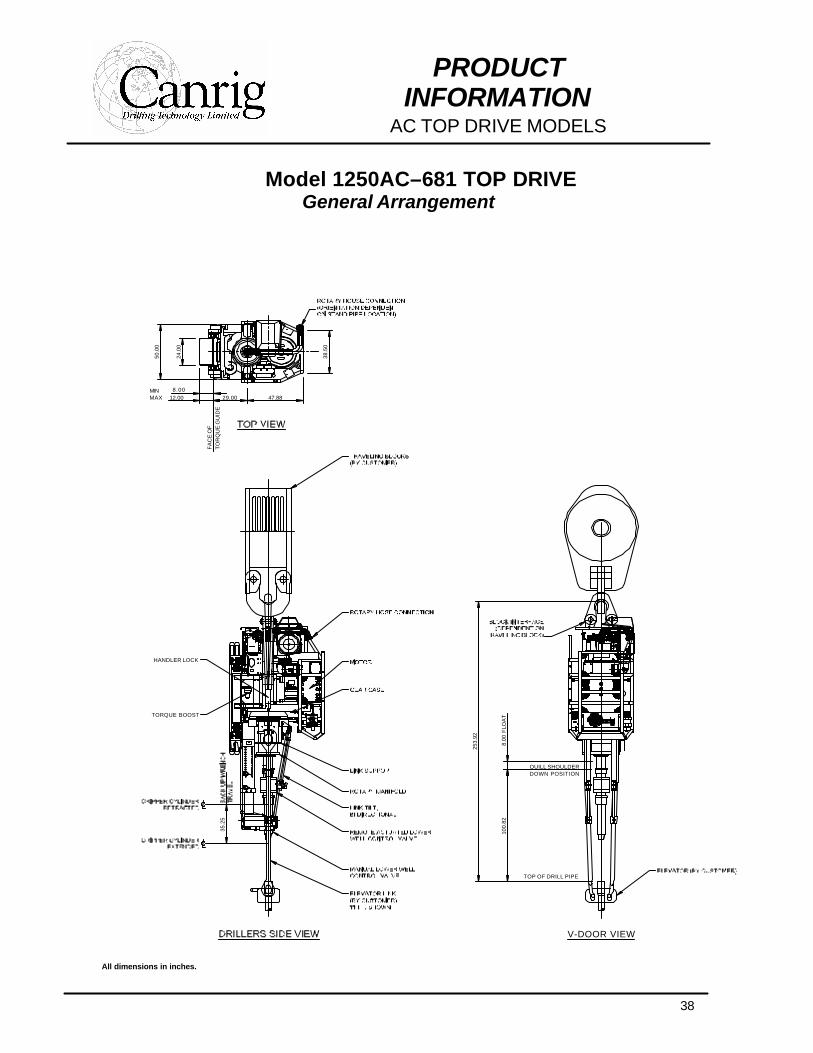
Model 1250AC–681 TOP DRIVE General Arrangement
All dimensions in inches.
35.2
5
TORQUE BOOST
HANDLER LOCK
TO
RQ
UE
GU
IDE
FA
CE
OF
29.0012.008.00
MAXMIN
24.0
0
50.0
0
47.88
38.5
0
V-DOOR VIEW
DOWN POSITION
TOP OF DRILL PIPE
QUILL SHOULDER
100.
82
253.
92
8.00
FLO
AT
39
PRODUCT INFORMATION
AC TOP DRIVE MODELS
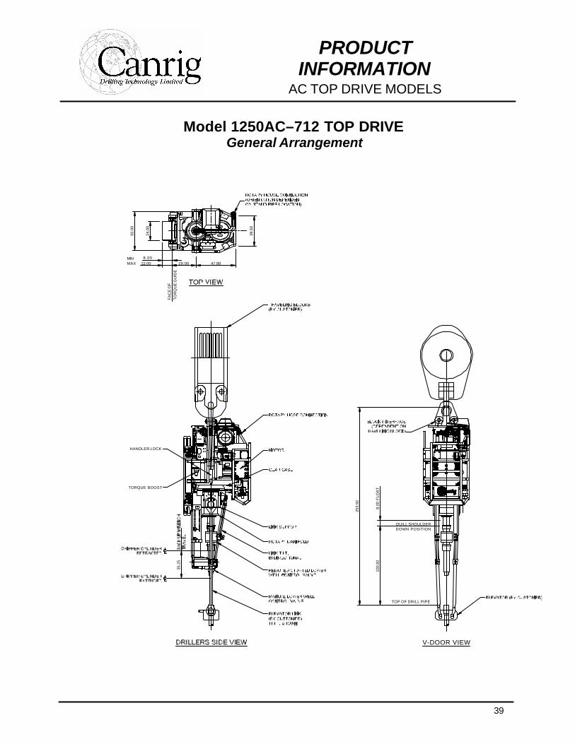
Model 1250AC–712 TOP DRIVE General Arrangement
35.2
5
TORQUE BOOST
HANDLER LOCK
TO
RQ
UE
GU
IDE
FA
CE
OF
29.0012.008.00
MAXMIN
24.0
0
50.0
0
47.88
38.5
0
V-DOOR VIEW
DOWN POSITION
TOP OF DRILL PIPE
QUILL SHOULDER
100.
82
253.
92
8.00
FLO
AT
40
PRODUCT INFORMATION
AC TOP DRIVE MODELS
All dimensions in inches.
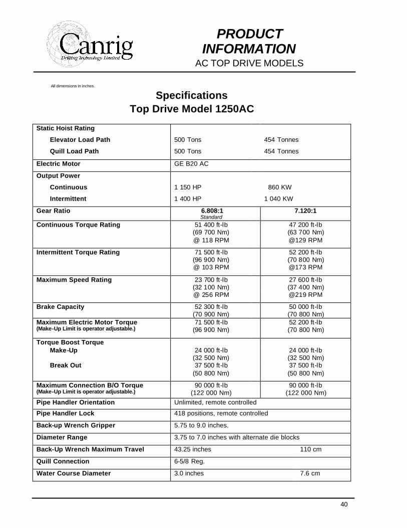
Specifications Top Drive Model 1250AC
Static Hoist Rating
Elevator Load Path 500 Tons 454 Tonnes
Quill Load Path 500 Tons 454 Tonnes
Electric Motor GE B20 AC
Output Power
Continuous 1 150 HP 860 KW
Intermittent 1 400 HP 1 040 KW
Gear Ratio 6.808:1 Standard
7.120:1
Continuous Torque Rating 51 400 ft-lb 47 200 ft-lb (69 700 Nm) (63 700 Nm) @ 118 RPM @129 RPM
Intermittent Torque Rating 71 500 ft-lb 52 200 ft-lb (96 900 Nm) (70 800 Nm) @ 103 RPM @173 RPM
Maximum Speed Rating 23 700 ft-lb 27 600 ft-lb (32 100 Nm) (37 400 Nm) @ 256 RPM @219 RPM
Brake Capacity 52 300 ft-lb (70 900 Nm)
50 000 ft-lb (70 800 Nm)
Maximum Electric Motor Torque 71 500 ft-lb 52 200 ft-lb (Make-Up Limit is operator adjustable.) (96 900 Nm) (70 800 Nm)
Torque Boost Torque Make-Up 24 000 ft-lb
(32 500 Nm) 24 000 ft-lb
(32 500 Nm) Break Out 37 500 ft-lb
(50 800 Nm)
37 500 ft-lb (50 800 Nm)
Maximum Connection B/O Torque 90 000 ft-lb 90 000 ft-lb (Make-Up Limit is operator adjustable.) (122 000 Nm) (122 000 Nm) Pipe Handler Orientation Unlimited, remote controlled
Pipe Handler Lock 418 positions, remote controlled
Back-up Wrench Gripper 5.75 to 9.0 inches.
Diameter Range 3.75 to 7.0 inches with alternate die blocks
Back-Up Wrench Maximum Travel 43.25 inches 110 cm
Quill Connection 6-5/8 Reg.
Water Course Diameter 3.0 inches 7.6 cm
41
PRODUCT INFORMATION
AC TOP DRIVE MODELS
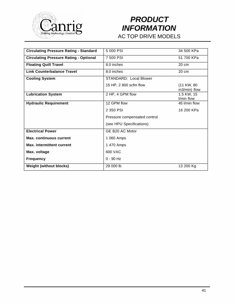
Circulating Pressure Rating - Standard 5 000 PSI 34 500 KPa
Circulating Pressure Rating - Optional 7 500 PSI 51 700 KPa
Floating Quill Travel 8.0 inches 20 cm
Link Counterbalance Travel 8.0 inches 20 cm
Cooling System STANDARD: Local Blower
15 HP, 2 800 scfm flow (11 KW, 80 m3/min) flow
Lubrication System 2 HP, 4 GPM flow 1.5 KW, 15 l/min flow
Hydraulic Requirement 12 GPM flow 45 l/min flow
2 350 PSI 16 200 KPa
Pressure compensated control
(see HPU Specifications)
Electrical Power GE B20 AC Motor
Max. continuous current 1 060 Amps
Max. intermittent current 1 470 Amps
Max. voltage 600 VAC
Frequency 0 - 90 Hz
Weight (without blocks) 29 000 lb 13 200 Kg
42
PRODUCT INFORMATION
AC TOP DRIVE MODELS
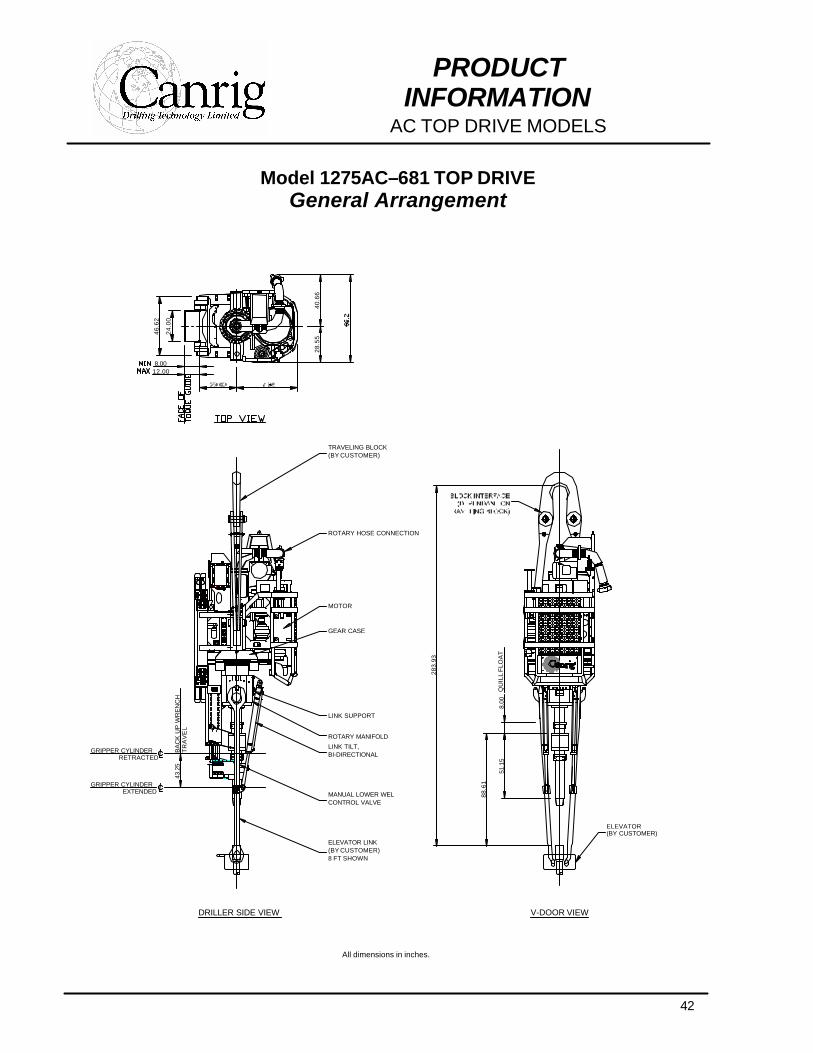
Model 1275AC–681 TOP DRIVE General Arrangement
All dimensions in inches.
88.6
1
51.1
58.
00
283.
93
MOTOR
RETRACTED
GRIPPER CYLINDEREXTENDED
GRIPPER CYLINDER
DRILLER SIDE VIEW
ELEVATOR LINK(BY CUSTOMER)8 FT SHOWN
MANUAL LOWER WELCONTROL VALVE
LINK TILT,BI-DIRECTIONAL
ROTARY MANIFOLD
LINK SUPPORT
GEAR CASE
43.2
5B
AC
K U
P W
RE
NC
HT
RA
VE
L
QU
ILL
FLO
AT
12.008.00
46.6
2
28.5
5
ROTARY HOSE CONNECTION
TRAVELING BLOCK(BY CUSTOMER)
24.0
0
40.6
6
V-DOOR VIEW
ELEVATOR(BY CUSTOMER)
43
PRODUCT INFORMATION
AC TOP DRIVE MODELS
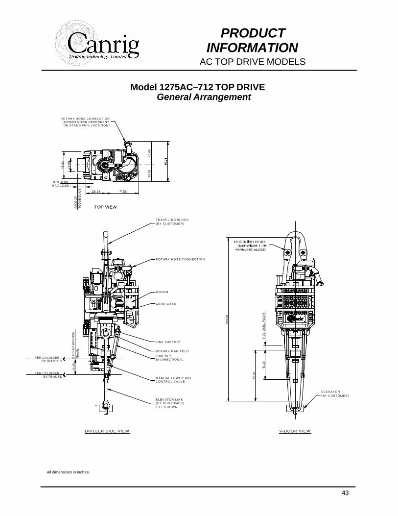
Model 1275AC–712 TOP DRIVE General Arrangement
All dimensions in inches.
8.0
051
.15RETRACTED
GRIPPER CYLINDERE X T E N D E D
GRIPPER CYLINDER
DRILLER SIDE VIEW
G E A R C A S E
LINK SUPPORT
ROTARY MANIFOLD
BI-DIRECTIONALLINK TILT,
C O N T R O L V A L V EM A N U A L L O W E R W E L
8 F T S H O W N( B Y C U S T O M E R )ELEVATOR L INK
43.2
5B
AC
K U
P W
RE
NC
H
TRA
VE
L
88.6
1
QU
ILL
FLO
AT
283.
93
ROTARY HOSE CONNECTION(ORIENTATION DEPENDENTON STAND P IPE LOCATION)
12.008.00
46.6
2
M INM A X
28.5
5
( B Y C U S T O M E R )T R A V E L I N G B L O C K
ROTARY HOSE CONNECTION
MOTOR
TO
QU
E G
UID
EF
AC
E O
F
24.0
0
40.6
6
V-DOOR VIEW
(BY CUSTOMER)E L E V A T O R
44
PRODUCT INFORMATION
AC TOP DRIVE MODELS
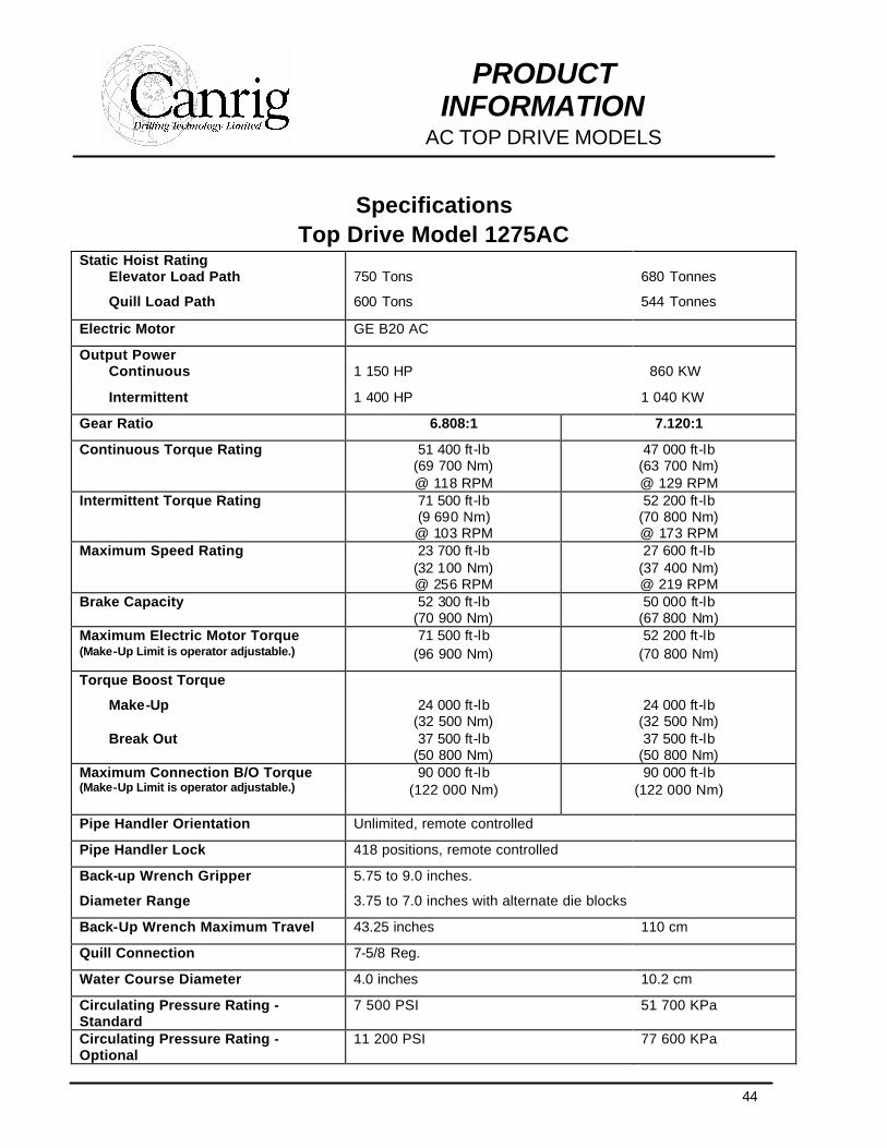
Specifications Top Drive Model 1275AC
Static Hoist Rating Elevator Load Path 750 Tons 680 Tonnes
Quill Load Path 600 Tons 544 Tonnes
Electric Motor GE B20 AC
Output Power Continuous 1 150 HP 860 KW
Intermittent 1 400 HP 1 040 KW
Gear Ratio 6.808:1 7.120:1
Continuous Torque Rating 51 400 ft-lb (69 700 Nm) @ 118 RPM
47 000 ft-lb (63 700 Nm) @ 129 RPM
Intermittent Torque Rating 71 500 ft-lb (9 690 Nm) @ 103 RPM
52 200 ft-lb (70 800 Nm) @ 173 RPM
Maximum Speed Rating 23 700 ft-lb (32 100 Nm) @ 256 RPM
27 600 ft-lb (37 400 Nm) @ 219 RPM
Brake Capacity 52 300 ft-lb (70 900 Nm)
50 000 ft-lb (67 800 Nm)
Maximum Electric Motor Torque 71 500 ft-lb 52 200 ft-lb (Make-Up Limit is operator adjustable.) (96 900 Nm) (70 800 Nm)
Torque Boost Torque
Make-Up 24 000 ft-lb (32 500 Nm)
24 000 ft-lb (32 500 Nm)
Break Out 37 500 ft-lb (50 800 Nm)
37 500 ft-lb (50 800 Nm)
Maximum Connection B/O Torque (Make-Up Limit is operator adjustable.)
90 000 ft-lb (122 000 Nm)
90 000 ft-lb (122 000 Nm)
Pipe Handler Orientation Unlimited, remote controlled
Pipe Handler Lock 418 positions, remote controlled
Back-up Wrench Gripper 5.75 to 9.0 inches.
Diameter Range 3.75 to 7.0 inches with alternate die blocks
Back-Up Wrench Maximum Travel 43.25 inches 110 cm
Quill Connection 7-5/8 Reg.
Water Course Diameter 4.0 inches 10.2 cm
Circulating Pressure Rating - Standard
7 500 PSI 51 700 KPa
Circulating Pressure Rating - Optional
11 200 PSI 77 600 KPa
45
PRODUCT INFORMATION
AC TOP DRIVE MODELS
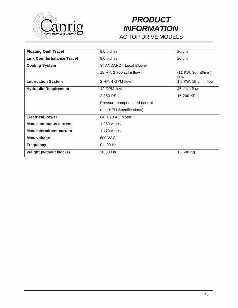
Floating Quill Travel 8.0 inches 20 cm
Link Counterbalance Travel 8.0 inches 20 cm
Cooling System STANDARD: Local Blower
15 HP, 2 800 scfm flow (11 KW, 80 m3/min) flow
Lubrication System 2 HP, 4 GPM flow 1.5 KW, 15 l/min flow
Hydraulic Requirement 12 GPM flow 45 l/min flow
2 350 PSI 16 200 KPa
Pressure compensated control
(see HPU Specifications)
Electrical Power GE B20 AC Motor
Max. continuous current 1 060 Amps
Max. intermittent current 1 470 Amps
Max. voltage 600 VAC
Frequency 0 – 90 Hz
Weight (without blocks) 30 000 lb 13 600 Kg
46
PRODUCT INFORMATION
AC TOP DRIVE MODELS
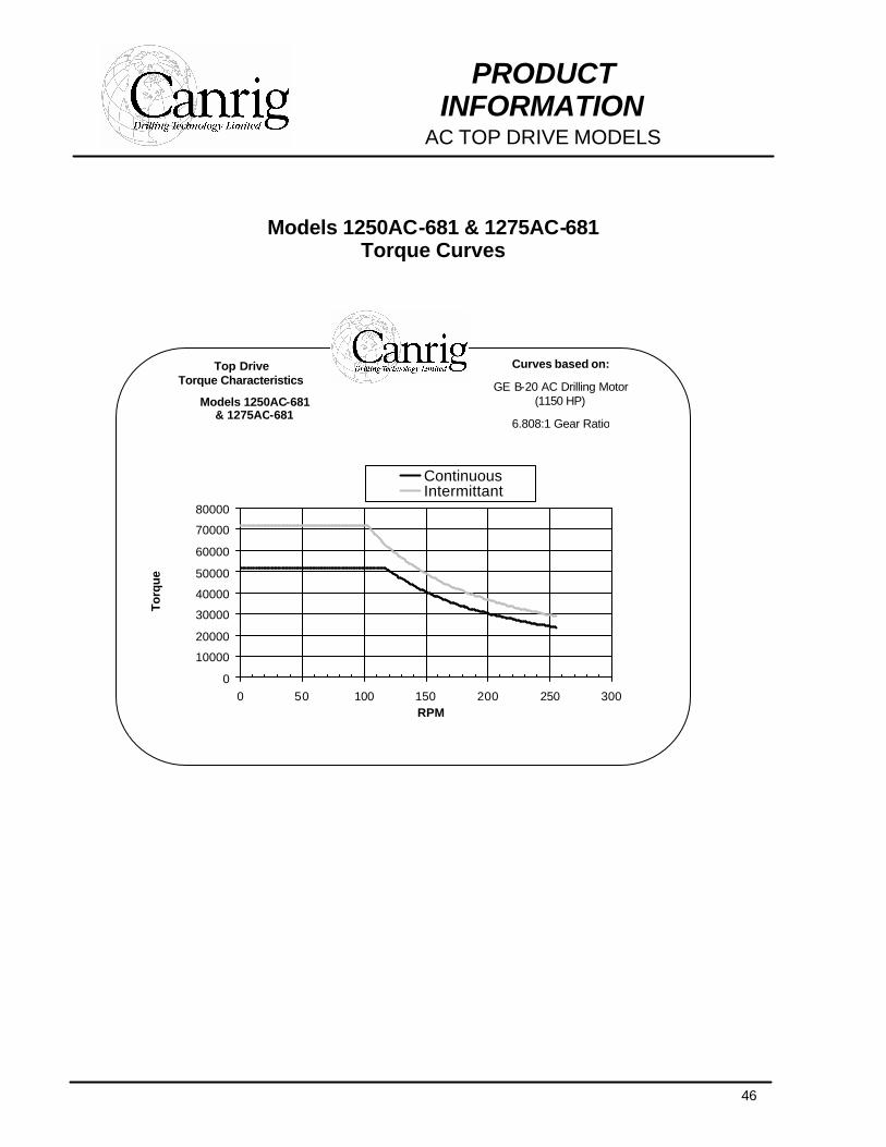
Models 1250AC-681 & 1275AC-681 Torque Curves
Top Drive Torque Characteristics
Models 1250AC-681 & 1275AC-681
Curves based on:
GE B-20 AC Drilling Motor (1150 HP)
6.808:1 Gear Ratio
0
10000
20000
30000
40000
50000
60000
70000
80000
0 50 100 150 200 250 300RPM
Torq
ue
ContinuousIntermittant

47
PRODUCT INFORMATION
TORQUE GUIDES
48
PRODUCT INFORMATION
TORQUE GUIDES
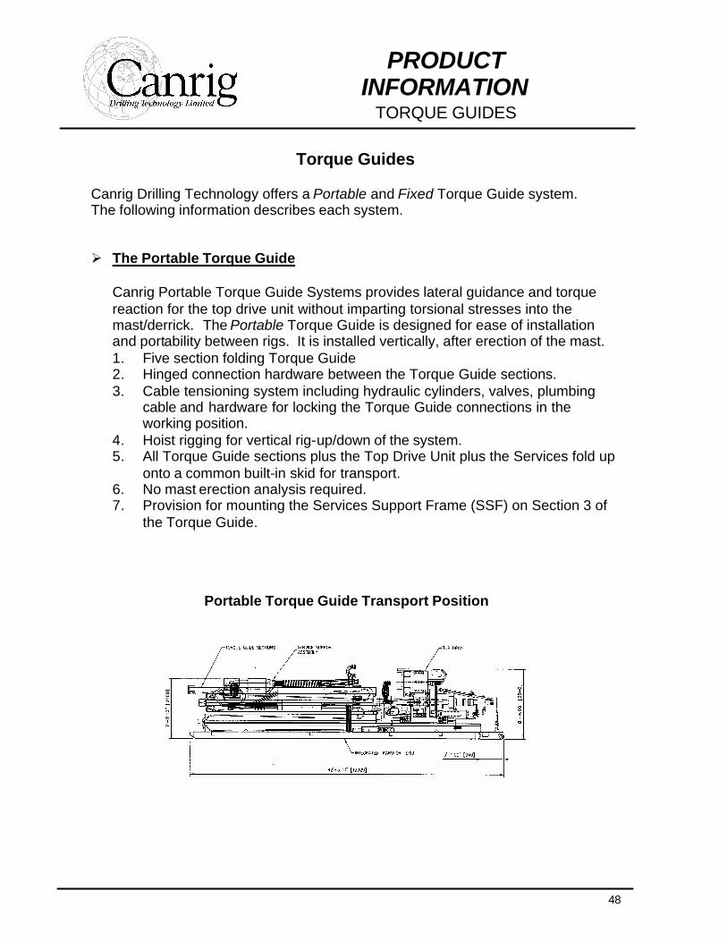
Torque Guides Canrig Drilling Technology offers a Portable and Fixed Torque Guide system. The following information describes each system. Ø The Portable Torque Guide
Canrig Portable Torque Guide Systems provides lateral guidance and torque reaction for the top drive unit without imparting torsional stresses into the mast/derrick. The Portable Torque Guide is designed for ease of installation and portability between rigs. It is installed vertically, after erection of the mast. 1. Five section folding Torque Guide 2. Hinged connection hardware between the Torque Guide sections. 3. Cable tensioning system including hydraulic cylinders, valves, plumbing
cable and hardware for locking the Torque Guide connections in the working position.
4. Hoist rigging for vertical rig-up/down of the system. 5. All Torque Guide sections plus the Top Drive Unit plus the Services fold up
onto a common built-in skid for transport. 6. No mast erection analysis required. 7. Provision for mounting the Services Support Frame (SSF) on Section 3 of
the Torque Guide.
Portable Torque Guide Transport Position
49
PRODUCT INFORMATION
TORQUE GUIDES
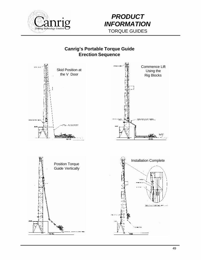
Canrig’s Portable Torque Guide Erection Sequence
Skid Position at the V Door
Position Torque Guide Vertically
Installation Complete
Commence Lift Using the
Rig Blocks
50
PRODUCT INFORMATION
TORQUE GUIDES
Ø Top Drive Services – Self Contained (Portable)
Provisions for electric and hydraulic services are built into the Folding Torque Guide. The system requires little or no interface to the rig and minimal connections for rig-up. 1. Adjustable Services Support Frame (SSF), mounted to Section 3 of the
Torque Guide and positioned at approximately 75 ft. elevation above the floor, for support of the service loops and Upper Torque Guide Junction Box.
2. Lower Torque Guide Junction Box for connection of the supply cables to the Torque Guide electrical cables.
3. Torque Guide electrical cables from the Lower Torque Guide Junction Box to the Upper Torque Guide Junction Box. These cables are fixed to the Torque Guide sections and fold with the Torque Guide for transport.
4. Upper Torque Guide Junction Box for connection of the Torque Guide electrical cables to the electrical service loop.
5. Hydraulic supply and return lines from the base of the Torque Guide to the SSF. These lines are fixed to the Torque Guide sections and fold with the Torque Guide for transport.
6. Electric Service Loop including power and control cables from the SSF to the Top Drive Unit (TDU). The Electric Service Loop is transported on the collapsed Torque Guide skid.
7. Hydraulic Service Loop, including pressure and return lines, from the SSF to the TDU. The Hydraulic Service Loop is transported on the collapsed Torque Guide skid.
51
PRODUCT INFORMATION
TORQUE GUIDES
Ø The Fixed Torque Guide Canrig Torque Guide Systems provides lateral guidance and torque reaction for the top drive unit without imparting torsional stresses into the mast/derrick. The Flanged Type Torque Guide is divided into sections corresponding to the mast sections. Each guide section is laterally fixed to its mast section with torque-isolating connections. The Torque Guide sections are joined with bolted flanges. Subject to mast erection stress constraints, the Flanged Torque Guide can be installed horizontally and erected with the mast. 1. Four (+/-) section Torque Guide, custom built for the mast/derrick. 2. Flange connections between the sections. 3. Mast connection brackets (2 per section):
• Torque isolating. • Free axial movement of the torque guide relative to the mast/derrick. • Adjustable lateral positioning. • Welded attachment to the mast girts (Standard); clamped-style
optional. 4. Transport Skid for the Top Drive Unit built into the bottom section of the
Torque Guide. 5. Application engineering and installation drawings. 6. Mast erection stress analysis and any associated mast upgrades are
excluded. 7. Installation, alignment and labor costs are excluded.
Ø Top Drive Services – Mast/Derrick Mounted (Fixed)
Provisions for electric and hydraulic services are installed onto the mast/derrick.
1. Mast/Derrick Junction Box, shipped loose. Provisions for hard-wired connections are included for both the feeder and Electric Service Loop sides.
2. Electric Service Loop, including power and control cables, from the Mast/Derrick Junction Box to the Top Drive Unit (TDU). ESL/TDU connections are hard wired.
3. Hydraulic Service Loop, including pressure and return lines, from the mast/derrick termination to the TDU.
4. OPTION – Feeder Electric Service Loop and Floor Junction Box: • Floor Junction Box for connection of the supply cables to the
mast/derrick feeder cables. • Electric Service Loop for stationary application between the Floor
Junction Box and the Mast/Derrick Junction Box.

52
PRODUCT INFORMATION
ELECTRICAL AND HYDRAULIC
Electrical and Hydraulic Configurations
The Canrig Top Drive Support Unit is a self-contained power and control package that is an integral element of the Canrig Portable Top Drive System.
Ø The Top Drive Support Unit (TDSU)
Requires only 600V power from rig or standalone genset 1. Standard Compact TDSU Micro Building:
• Four-point crane-lift style. • Dimensions as per Specifications. • Enclosed SCR/ VFD/Control room
2. DC models c/w a SCR. 3. AC models c/w a Flux-Vector Variable Frequency Drive.
• Six pulse VFD rectifier with a 810 VDC link for near-unity power factor load.
• Modular drive configuration with three identical inverter modules. • User friendly message display panel, with built-in self-diagnostics. • Internal air cooling system.
4. Top Drive Control & Interface Panel (CIP): • CIP cabinet for Safe Area installation; standard dimensions. • On Shunt DC models a Dual (redundant) field supplies for the top
drive, c/w static reversing and field weakening (3 levels). • HPU motor controls. • Supply breaker for the On-Board MCC. • Control Power Transformer and Regulator. • Top drive control PLC:
î Chassis. î Processor c/w EEPROM memory module. î Proprietary Canrig TD System Control Logic. î Input and output devices for local functions. î Communications adapter for the TD Control Console, TDU
Flex I/O and Advanced Diagnostic System. • Power supplies (dual, redundant) for the Flex I/O on the Top Drive
Unit. • Communications interface to the Flex I/O on the Top Drive Unit. • Interface connections to the SCR / VFD, TD Control Console and the
Top Drive Unit. • Control cables between the CIP and the TD Control Console.
5. Dual (redundant) air conditioners for the SCR / VFD/Control room.
53
PRODUCT INFORMATION
ELECTRICAL AND HYDRAULIC
6. Twin Hydraulic Power Unit for auxiliary functions: • Twin, fully redundant, electrically driven hydraulic pump assemblies. • Suction, pressure and return filtration. • Air to oil cooling system. • Stainless steel reservoir. • Kidney loop cooling and filtration circulation system. • Temperature and oil level alarm sensors. • Unitized skid package c/w drip tray.
7. Electrical Cables/Hydraulic Hoses: • Power Cables - TDSU to Lower Torque Guide Junction Box. • Control Cables:
î TDSU to Lower Torque Guide Junction Box î TDSU to the Rig SCR / VFD (for optional power limit and mud
pump status signals). • Hydraulic Lines from the TDSU to the Torque Guide base, c/w
connectors. 8. Pre-commissioned. 9. Optionally available is a Land-Configuration TDSU Packaging Upgrade:
• 40 ft Oilfield-style skid. • Mounting provisions for the Sub-Compact TDSU Building • Full-length roof. • Enclosed Parts Storage room (N/A w/ Genset Upgrade). • Grasshopper mounting pedestal. • Articulated grasshopper-type cable tray system for support of the
electrical cables and hydraulic hoses between the TDSU and the rig floor. The grasshopper folds for transport on the TDSU.
• Storage provision for the TDSU supply cables. NOTE: The only required electrical interface to the rig is a 600 VAC supply to
the TDSU. Additional control interfaces to the rig's power limit and mud pump status are also recommended.
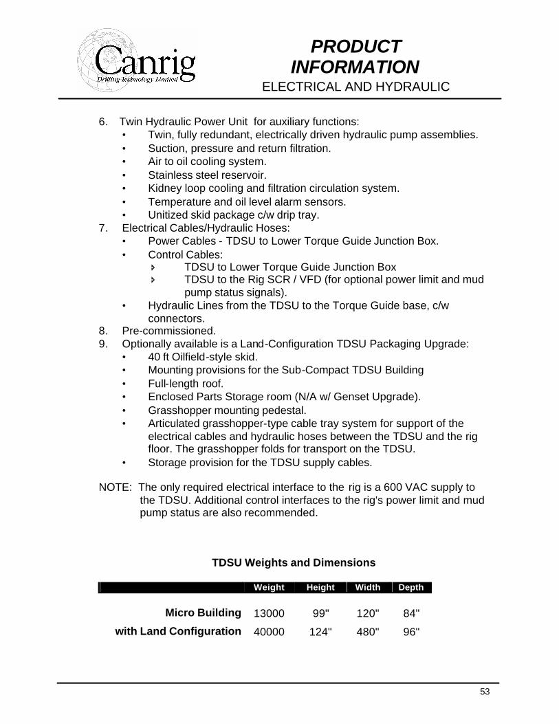
TDSU Weights and Dimensions
Weight Height Width Depth
Micro Building 13000 99" 120" 84"
with Land Configuration 40000 124" 480" 96"
54
PRODUCT INFORMATION
ELECTRICAL AND HYDRAULIC
Ø Electrical Interface Materials for TDSU Applications
1. Feeder Breaker Assembly (to supply 600 VAC power to the TDSU): • Feeder Breaker Enclosure, to be mounted at the rig’s SCR building,
normally within 10 ft. of the 600 VAC bus. • Feeder Breaker. • Interface Power Cables - Rig Power Bus to Feeder Breaker:
î Recommended maximum run length = 10 ft. î Run length supplied = 20 ft. î Bolted terminations both ends.
2. TDSU Supply Cables: • Standard run length = 100 ft. • Additional run length available and price separately. • TDSU end terminations - Bolted; pre-terminated. • Feeder Breaker end terminations - Finney lugs; pre-terminated. • Typically the TDSU Supply Cables are integrated with the TDSU.
55
PRODUCT INFORMATION
ELECTRICAL AND HYDRAULIC
Alternative electrical power provisions in a stand alone configuration
Ø Control and Interface Panel
Requires DC power form dedicated SCR bay This alternative is possible for new rigs or rigs with an existing SCR assignment available for the top drive. This CIP proposal is conditional on the suitability of the existing SCR system.
1. Field Supply for the top drive, c/w static reversing and field weakening (3 levels). Requires a 480 or 600 V supply and 60-amp breaker.
2. Motor Controls for the HPU, blower and lube pump. Requires a 480 V power supply and a 100-amp breaker.
3. Control Power Regulator 4. Top drive control PLC with interface connections to the Transfer Contactors,
Field Supply and Motor Controls and interface terminations for connection to the SCR, the Top Drive Control Console and the Top Drive Unit.
5. Electrical interface engineering including interface documentation. 6. Control cable and connectors from the CIP to the Top Drive Control Console.
Ø Transfer Panel Unit (TPU) DC power from SCR bay, provides transfer function to allow same SCR to be switched to other applications This alternative is possible only for rigs with independent rotary table drive. This TPU proposal is conditional on the suitability of the existing SCR system. For rigs without independent rotary drive or to minimize installation time and cost, we recommend an independent SCR bay for the top drive; see Item 7.
1. Transfer Contactors for assignment of the rig's existing SCR bridge to either
the top drive or the rotary table. The Transfer Panel will be located in a non-hazardous area.
2. Finney connections for the top drive and rotary table power cables. 3. Field Supply for the top drive, c/w static reversing and field weakening (3
levels). Requires a 480 or 600 V supply and 60-amp breaker. 4. Motor Controls for the HPU, blower and lube pump. Requires a 480 V power
supply and a 100-amp breaker. 5. Control Power Regulator.
56
PRODUCT INFORMATION
ELECTRICAL AND HYDRAULIC
6. Top drive control PLC with interface connections to the Transfer Contactors, Field Supply and Motor Controls and interface terminations for connection to the SCR, the Top Drive Control Console and the Top Drive Unit.
7. Electrical interface engineering including interface documentation. 8. Control cable and connectors from the Transfer Panel to the Top Drive
Control Console (Item 2).
Ø Twin Hydraulic Power Unit (HPU)
For auxiliary hydraulic functions
1. Twin, fully redundant, electrically driven hydraulic pumps, each 20 HP, 12 GPM, 2500 PSI
2. Suction, pressure and return filtration 3. Air to oil cooling system 4. Stainless steel reservoir, 60 gallon 5. Kidney loop cooling and filtration circulation system 6. Temperature and oil level alarm sensors 7. Unitized skid package c/w drip tray
57
PRODUCT INFORMATION
TOP DRIVE CONTROL CONSOLE
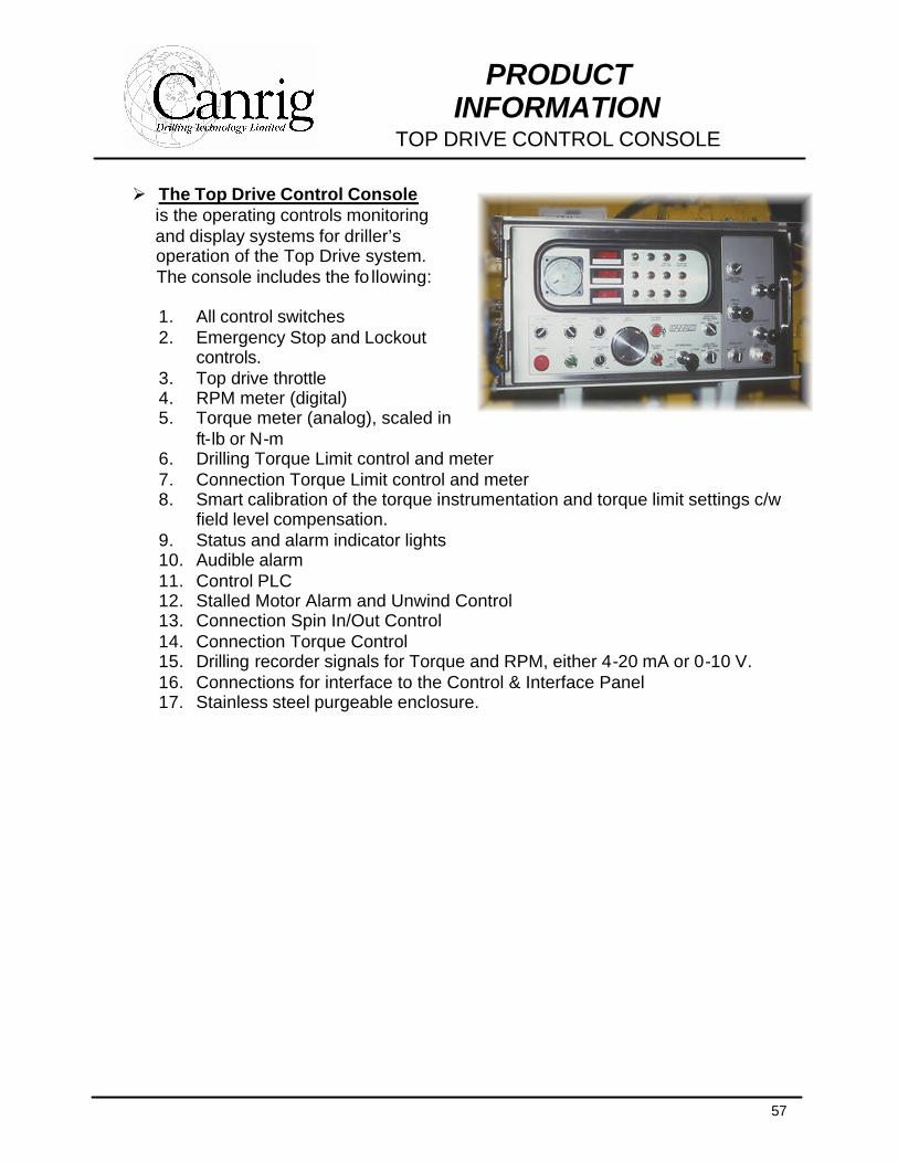
Ø The Top Drive Control Console is the operating controls monitoring and display systems for driller’s operation of the Top Drive system. The console includes the fo llowing:
1. All control switches 2. Emergency Stop and Lockout
controls. 3. Top drive throttle 4. RPM meter (digital) 5. Torque meter (analog), scaled in
ft-lb or N-m 6. Drilling Torque Limit control and meter 7. Connection Torque Limit control and meter 8. Smart calibration of the torque instrumentation and torque limit settings c/w
field level compensation. 9. Status and alarm indicator lights 10. Audible alarm 11. Control PLC 12. Stalled Motor Alarm and Unwind Control 13. Connection Spin In/Out Control 14. Connection Torque Control 15. Drilling recorder signals for Torque and RPM, either 4-20 mA or 0-10 V. 16. Connections for interface to the Control & Interface Panel 17. Stainless steel purgeable enclosure.
58
PRODUCT INFORMATION
ADVANCED DIAGNOSTICS SYSTEM
Auxiliary Mode
HelpScreen
RESETBlownFuse
2H:MN NN/DD/YY
BUWOpen
UWCVOpen
ConsoleNormal
LinkTiltMaintain
HandlerBypassed
MotorStalled
HandlerForward
HPU HiTemp
BrakeON
TrqBoostDiseng.
LWCVOpen
TD LowHyd Pressure
Low Speed
FieldFault
SCRNormal
MCCBlown Fuse
Push toCleanScreen
AckAll
s
t
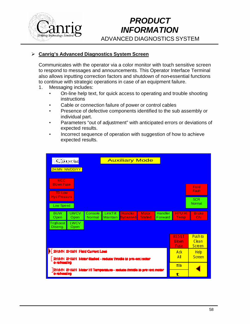
Ø Canrig’s Advanced Diagnostics System Screen
Communicates with the operator via a color monitor with touch sensitive screen to respond to messages and announcements. This Operator Interface Terminal also allows inputting correction factors and shutdown of non-essential functions to continue with strategic operations in case of an equipment failure. 1. Messaging includes:
• On-line help text, for quick access to operating and trouble shooting instructions
• Cable or connection failure of power or control cables • Presence of defective components identified to the sub assembly or
individual part. • Parameters “out of adjustment” with anticipated errors or deviations of
expected results. • Incorrect sequence of operation with suggestion of how to achieve
expected results.
59
PRODUCT INFORMATION
INSTALLATION AND CREW TRAINING
Ø Installation, Start-up and On-site Crew Training Services At the time of purchase, Canrig offers Top Drive Technicians at a flat rate for up to 35 man days including travel time for the initial Installation and Start-up. These technicians during the installation will provide crew training for:
î Daily maintenance î Operation of equipment î Basic Troubleshooting î Rig up and rig down procedures î Parts book review and parts ordering procedures î Supervise the installation and commissioning of the complete
system.
Ø Training at the Canrig Manufacturing Facility
Canrig offers a variety of detailed training. Technical overview courses cover functionality of the Top Drive and its associated systems. Detailed courses are available which cover the Top Drive’s mechanical, hydraulic and electrical systems as well as maintenance and service. Our classes also include parts book familiarization and troubleshooting. Quality hands-on experience balanced with an informal class setting is geared towards Top Drive operating and maintenance personnel. Classes are usually from 2 to 5 days and safety is emphasized throughout our training programs.
60
PRODUCT INFORMATION
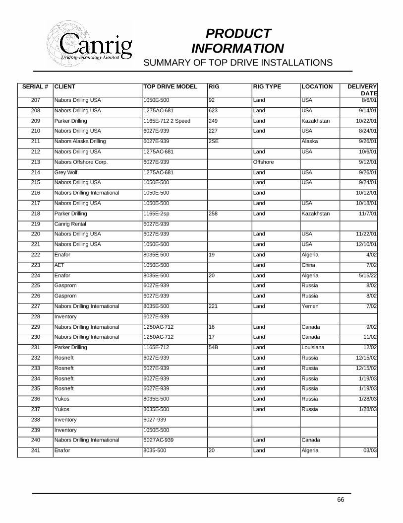
SUMMARY OF TOP DRIVE INSTALLATIONS
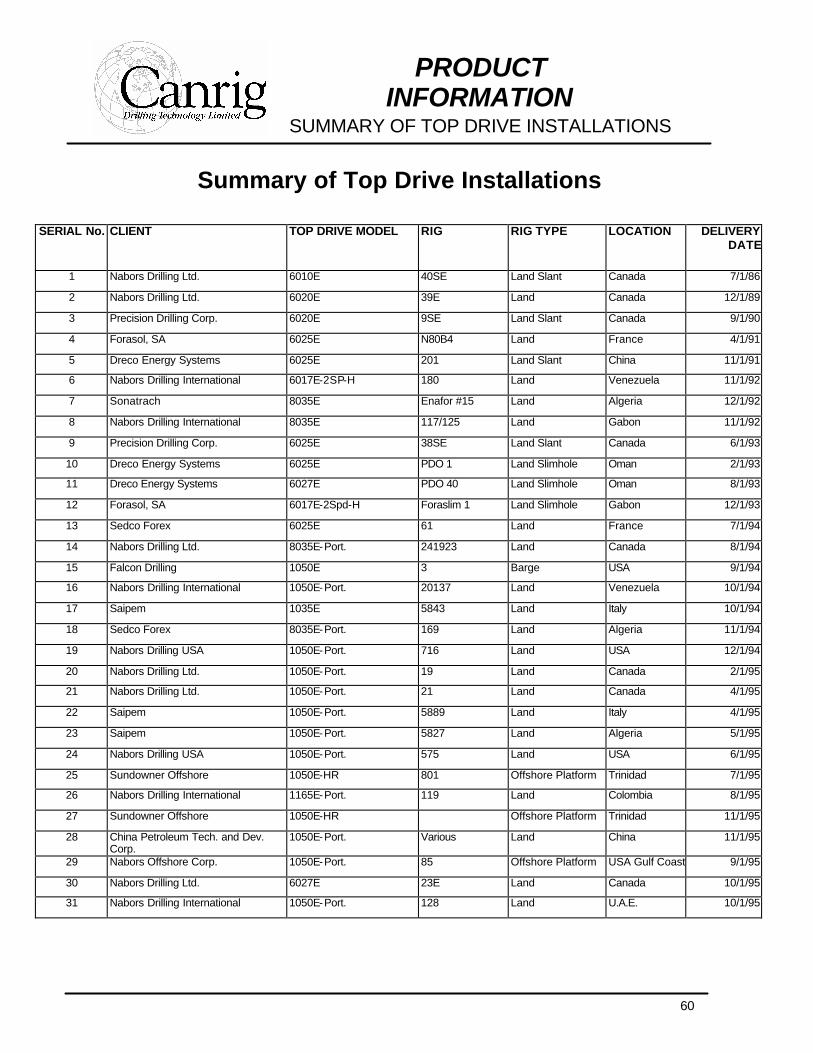
Summary of Top Drive Installations
SERIAL No. CLIENT TOP DRIVE MODEL RIG RIG TYPE LOCATION DELIVERY DATE
1 Nabors Drilling Ltd. 6010E 40SE Land Slant Canada 7/1/86
2 Nabors Drilling Ltd. 6020E 39E Land Canada 12/1/89
3 Precision Drilling Corp. 6020E 9SE Land Slant Canada 9/1/90
4 Forasol, SA 6025E N80B4 Land France 4/1/91
5 Dreco Energy Systems 6025E 201 Land Slant China 11/1/91
6 Nabors Drilling International 6017E-2SP-H 180 Land Venezuela 11/1/92
7 Sonatrach 8035E Enafor #15 Land Algeria 12/1/92
8 Nabors Drilling International 8035E 117/125 Land Gabon 11/1/92
9 Precision Drilling Corp. 6025E 38SE Land Slant Canada 6/1/93
10 Dreco Energy Systems 6025E PDO 1 Land Slimhole Oman 2/1/93
11 Dreco Energy Systems 6027E PDO 40 Land Slimhole Oman 8/1/93
12 Forasol, SA 6017E-2Spd-H Foraslim 1 Land Slimhole Gabon 12/1/93
13 Sedco Forex 6025E 61 Land France 7/1/94
14 Nabors Drilling Ltd. 8035E-Port. 241923 Land Canada 8/1/94
15 Falcon Drilling 1050E 3 Barge USA 9/1/94
16 Nabors Drilling International 1050E-Port. 20137 Land Venezuela 10/1/94
17 Saipem 1035E 5843 Land Italy 10/1/94
18 Sedco Forex 8035E-Port. 169 Land Algeria 11/1/94
19 Nabors Drilling USA 1050E-Port. 716 Land USA 12/1/94
20 Nabors Drilling Ltd. 1050E-Port. 19 Land Canada 2/1/95
21 Nabors Drilling Ltd. 1050E-Port. 21 Land Canada 4/1/95
22 Saipem 1050E-Port. 5889 Land Italy 4/1/95
23 Saipem 1050E-Port. 5827 Land Algeria 5/1/95
24 Nabors Drilling USA 1050E-Port. 575 Land USA 6/1/95
25 Sundowner Offshore 1050E-HR 801 Offshore Platform Trinidad 7/1/95
26 Nabors Drilling International 1165E-Port. 119 Land Colombia 8/1/95
27 Sundowner Offshore 1050E-HR Offshore Platform Trinidad 11/1/95
28 China Petroleum Tech. and Dev. Corp.
1050E-Port. Various Land China 11/1/95
29 Nabors Offshore Corp. 1050E-Port. 85 Offshore Platform USA Gulf Coast 9/1/95
30 Nabors Drilling Ltd. 6027E 23E Land Canada 10/1/95
31 Nabors Drilling International 1050E-Port. 128 Land U.A.E. 10/1/95
61
PRODUCT INFORMATION
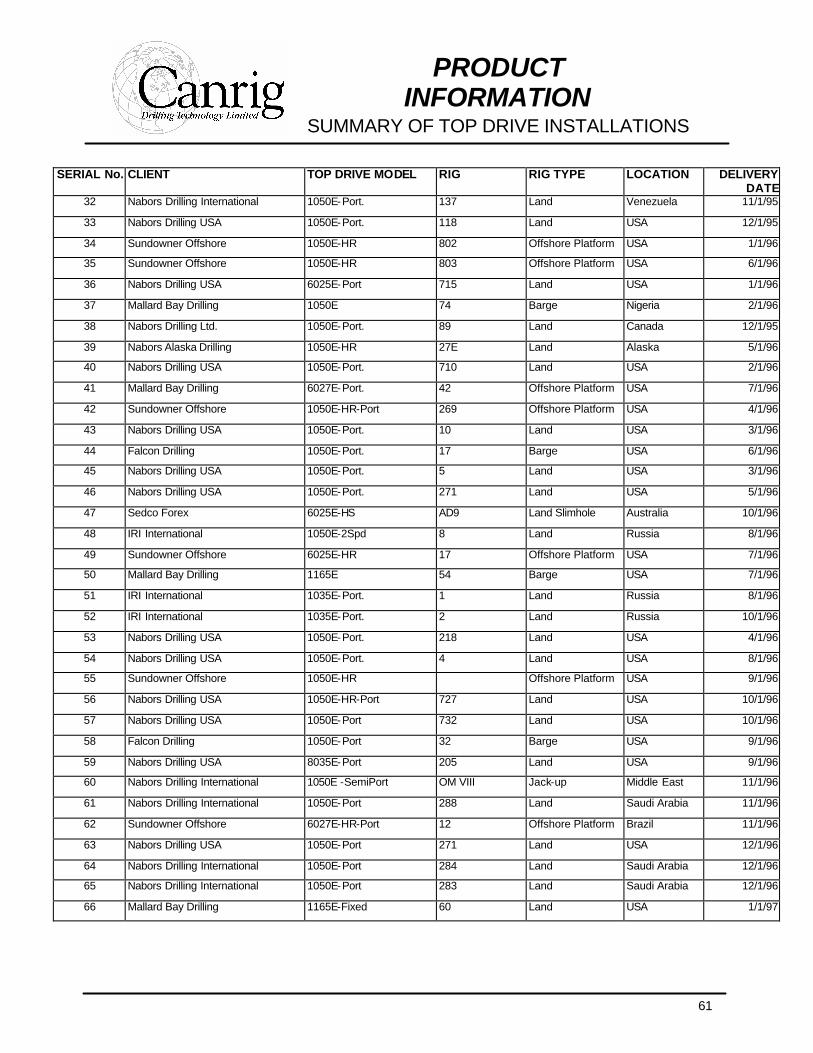
SUMMARY OF TOP DRIVE INSTALLATIONS
SERIAL No. CLIENT TOP DRIVE MODEL RIG RIG TYPE LOCATION DELIVERY DATE
32 Nabors Drilling International 1050E-Port. 137 Land Venezuela 11/1/95
33 Nabors Drilling USA 1050E-Port. 118 Land USA 12/1/95
34 Sundowner Offshore 1050E-HR 802 Offshore Platform USA 1/1/96
35 Sundowner Offshore 1050E-HR 803 Offshore Platform USA 6/1/96
36 Nabors Drilling USA 6025E-Port 715 Land USA 1/1/96
37 Mallard Bay Drilling 1050E 74 Barge Nigeria 2/1/96
38 Nabors Drilling Ltd. 1050E-Port. 89 Land Canada 12/1/95
39 Nabors Alaska Drilling 1050E-HR 27E Land Alaska 5/1/96
40 Nabors Drilling USA 1050E-Port. 710 Land USA 2/1/96
41 Mallard Bay Drilling 6027E-Port. 42 Offshore Platform USA 7/1/96
42 Sundowner Offshore 1050E-HR-Port 269 Offshore Platform USA 4/1/96
43 Nabors Drilling USA 1050E-Port. 10 Land USA 3/1/96
44 Falcon Drilling 1050E-Port. 17 Barge USA 6/1/96
45 Nabors Drilling USA 1050E-Port. 5 Land USA 3/1/96
46 Nabors Drilling USA 1050E-Port. 271 Land USA 5/1/96
47 Sedco Forex 6025E-HS AD9 Land Slimhole Australia 10/1/96
48 IRI International 1050E-2Spd 8 Land Russia 8/1/96
49 Sundowner Offshore 6025E-HR 17 Offshore Platform USA 7/1/96
50 Mallard Bay Drilling 1165E 54 Barge USA 7/1/96
51 IRI International 1035E-Port. 1 Land Russia 8/1/96
52 IRI International 1035E-Port. 2 Land Russia 10/1/96
53 Nabors Drilling USA 1050E-Port. 218 Land USA 4/1/96
54 Nabors Drilling USA 1050E-Port. 4 Land USA 8/1/96
55 Sundowner Offshore 1050E-HR Offshore Platform USA 9/1/96
56 Nabors Drilling USA 1050E-HR-Port 727 Land USA 10/1/96
57 Nabors Drilling USA 1050E-Port 732 Land USA 10/1/96
58 Falcon Drilling 1050E-Port 32 Barge USA 9/1/96
59 Nabors Drilling USA 8035E-Port 205 Land USA 9/1/96
60 Nabors Drilling International 1050E -SemiPort OM VIII Jack-up Middle East 11/1/96
61 Nabors Drilling International 1050E-Port 288 Land Saudi Arabia 11/1/96
62 Sundowner Offshore 6027E-HR-Port 12 Offshore Platform Brazil 11/1/96
63 Nabors Drilling USA 1050E-Port 271 Land USA 12/1/96
64 Nabors Drilling International 1050E-Port 284 Land Saudi Arabia 12/1/96
65 Nabors Drilling International 1050E-Port 283 Land Saudi Arabia 12/1/96
66 Mallard Bay Drilling 1165E-Fixed 60 Land USA 1/1/97
62
PRODUCT INFORMATION
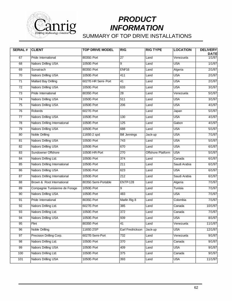
SUMMARY OF TOP DRIVE INSTALLATIONS
SERIAL # CLIENT TOP DRIVE MODEL RIG RIG TYPE LOCATION DELIVERY DATE
67 Pride International 8035E-Port 27 Land Venezuela 1/1/97
68 Nabors Drilling USA 1050E-Port 9 Land USA 1/1/97
69 Sonatrach 8035E-Port ENF16 Land Algeria 2/1/97
70 Nabors Drilling USA 1050E-Port 411 Land USA 2/1/97
71 Mallard Bay Drilling 6027E-HR Semi-Port 41 Land USA 2/1/97
72 Nabors Drilling USA 1050E-Port 633 Land USA 3/1/97
73 Pride International 8035E-Port 28 Land Venezuela 5/1/97
74 Nabors Drilling USA 1050E-Port 511 Land USA 3/1/97
75 Nabors Drilling USA 1050E-Port 206 Land USA 4/1/97
76 Roberds 6027E-Port Land Japan 5/1/97
77 Nabors Drilling USA 1050E-Port 130 Land USA 4/1/97
78 Nabors Drilling International 1050E-Port 125 Land Gabon 4/1/97
79 Nabors Drilling USA 1050E-Port 688 Land USA 5/1/97
80 Noble Drilling 1165E-2 spd Bill Jennings Jack-up USA 7/1/97
81 Nabors Drilling USA 1050E-Port 743 Land USA 5/1/97
82 Nabors Drilling USA 1050E-Port 670 Land USA 6/1/97
83 Sundowner Offshore 1050E-HR-Port 270 Offshore Platform USA 5/1/97
84 Nabors Drilling Ltd. 1050E-Port 374 Land Canada 6/1/97
85 Nabors Drilling International 1050E-Port 211 Land Saudi Arabia 6/1/97
86 Nabors Drilling USA 1050E-Port 623 Land USA 6/1/97
87 Nabors Drilling International 1050E-Port 212 Land Saudi Arabia 6/1/97
88 Brown & Root International 8035E-Semi-Portable ENTP-128 Land Algeria 7/1/97
89 Compagnie Tunisienne de Forage 1050E-Port 9 Land Tunisia 7/1/97
90 Nabors Drilling USA 1050E-Port 483 Land USA 7/1/97
91 Pride International 8035E-Port Marlin Rig 8 Land Colombia 7/1/97
92 Nabors Drilling Ltd. 6027E-Port 385 Land Canada 10/1/97
93 Nabors Drilling Ltd. 1050E-Port 372 Land Canada 7/1/97
94 Nabors Drilling USA 1050E-Port 939 Land USA 8/1/97
95 Flint 8035E-Port 41 Land Venezuela 11/1/97
96 Noble Drilling 1165E-2SP Earl Fredrickson Jack-up USA 12/1/97
97 Precision Drilling Corp. 6027E-Semi-Port 732 Land Venezuela 9/1/97
98 Nabors Drilling Ltd. 1050E-Port 370 Land Canada 9/1/97
99 Nabors Drilling USA 1050E-Port 409 Land USA 9/1/97
100 Nabors Drilling Ltd. 1050E-Port 375 Land Canada 9/1/97
101 Nabors Drilling USA 1050E-Port 393 Land USA 11/1/97

63
PRODUCT INFORMATION
SUMMARY OF TOP DRIVE INSTALLATIONS
SERIAL # CLIENT TOP DRIVE MODEL RIG RIG TYPE LOCATION DELIVERY DATE
102 Pemex 1050E-Port 324 Land Mexico 2/1/98
103 Sundowner Offshore 1165E-2SP 86 Offshore Platform USA 1/1/98
104 Mallard Bay Drilling 1050E-Port 50 Barge USA 12/1/97
105 Nabors Drilling USA 1050E-Port 90 Land USA 12/1/97
106 Nabors Drilling International 1165E-Port 20 Land Venezuela 11/1/97
107 Nabors Drilling Ltd. 1050E-Port 90 Land Canada 12/1/97
108 Apolo Ltd. 1050E-Port 33 Land Bolivia 2/1/98
109 Nabors Drilling Ltd. 1050E-Port 373 Land Canada 11/1/97
110 Century Drilling 1050E-Port 28 Land Thailand 4/1/98
111 Sundowner Offshore 6027E-Port 16 Offshore Platform USA 11/1/97
112 Compagnie Tunisienne de Forage 1050E-Port 4 Land Tunisia 12/1/98
113 Nabors Drilling International 8035E-500 98 Land
114 Pride International 8035E-Semi-Port 29 Land Venezuela 1/1/98
115 Pride International 8035E-Semi-Port 30 Land Venezuela 2/1/98
116 Nabors Drilling USA 6027E-Port 723 Land USA 2/1/98
117 Grey Wolf 1050E-500 80 Land USA 4/1/00
118 Cliffs Drilling 1050E 150 Jack-up USA 3/1/98
119 Nabors Alaska Drilling 8035E 9ES Land Alaska 4/1/98
120 Grey Wolf 1050E-500 91 Land Louisiana 11/1/99
121 Nabors Drilling USA 1165E 797 Land USA 6/1/98
122 Nabors Alaska Drilling 8035E 7ES Land Alaska 4/1/98
123 Nabors Drilling USA 6027E-938 123 Land USA 4/1/00
124 Dreco/Deutag 6027E T-69 Land Venezuela 10/1/98
125 Pride International 8035E 31 Columbia 12/1/99
126 IRI International 1050E-HR 8 Land Russia 9/1/98
127 Pride/Foramer 1050E-HR Ile du Levant Jack-up Venezuela 5/1/98
128 Sinopec 1050E-Port 2 Land China 12/1/98
129 Nabors Drilling Ltd. 1050E-500 371 Land Canada 9/1/99
130 Pride/Foramer 1265 AC Pride Africa Drillship Angola 1/1/99
131 Nabors Alaska Drilling 1165E 28E Land Alaska 12/1/98
132 Nabors Drilling International 6027E 901 Offshore Platform Dubai 3/1/99
133 Pride/Foramer 1265 AC Pride Angola Drillship Angola 1/1/99
134 China Petroleum Tech. and Dev. Corp.
1050E-500 Hubai Land China 3/1/99
135 Sedco Forex 1275 AC SFX-Elf Semi-Sub Angola 5/1/99
136 Sedco Forex 1275 AC Sedco Energy Semi-Sub GOM 6/1/99

64
PRODUCT INFORMATION
SUMMARY OF TOP DRIVE INSTALLATIONS
SERIAL # CLIENT TOP DRIVE MODEL RIG RIG TYPE LOCATION DELIVERY DATE
137 Sedco Forex 1275 AC Cajun-Express Semi-Sub GOM 6/1/99
138 Dreco/Deutag 6027E T68 Land Venezuela 9/1/98
139 Daqing Pet. Bureau 6027E Slant Rig China 6/1/99
140 Sinopec 1050E-Port ZJ 70D Land China 12/1/98
141 Sedco Forex 1275 AC Trident 20 Jackup Caspian Sea 7/1/99
142 Hitech 1050E-2SP Hitdrill 1 Jackup India 9/1/99
143 Flint 6027E-773 42 Land Venezuela 1/1/00
144 Precision Drilling Corp. 6027E-939 736 Land Venezuela 11/1/99
145 Precision Drilling Corp. 6027E-939 737 Land Venezuela 1/1/00
146 Flint 6027E-939 43 Land Venezuela 2/1/00
147 Nabors Drilling USA 1165E-712 304 Land Louisiana 1/1/00
148 Nabors Drilling International 1165E-712 119 Land Columbia 3/1/00
149 Nabors Drilling International 1050E-500 217 Land Yemen 2/1/00
150 Nabors Drilling USA 1050E-500 732 Land Texas 3/1/00
151 Nabors Drilling USA 1275AC-681 304 Land USA 7/1/00
152 Nabors Drilling USA 6027E-939 353 Land New Mexico 4/1/00
153 Pride/Foramer 1275AC-681 Africa Offshore Platform Offshore Angola
2/1/00
154 Nabors Drilling International 1050E-500 116 Land 8/1/00
155 Grey Wolf 1050E-500 90 Land Louisiana 4/1/00
156 Nabors Drilling USA 1275AC-681 411 Land USA 9/1/00
157 Nabors Drilling USA 1050E-500 298 Land USA 5/1/00
158 Grey Wolf 1050E-500 79 Land USA 8/1/00
159 Grey Wolf 1275AC-681 558 Land USA 8/1/00
160 Nabors Drilling Ltd. 6027E-939 384 Land Saskatchewan 6/1/00
161 Sinopec 1050E-500 3 China 7/1/00
162 Nabors Offshore Corp. 6027E-939 13 Offshore Italy 7/1/00
163 Nabors Drilling USA 1275AC-681 411 Land USA 9/1/00
164 Sinopec 1050E-500 4 China 7/1/00
165 Grey Wolf 1050E-500 505 Land USA 9/1/00
166 Nabors Drilling USA 6027E-939 360 Land USA 12/1/00
167 Grey Wolf 1050E-500 78 Land USA 10/1/00
168 Nabors Drilling USA 1050E-500 310 Land USA 10/1/00
169 Precision Drilling Corp. 6027E-939 738 Land Venezuela 10/1/00
170 Nabors Offshore Corp. 1050E-712 302 Offshore 10/1/00
171 Nabors Offshore Corp. 1050E-712 802 Offshore GOM 11/1/00
65
PRODUCT INFORMATION
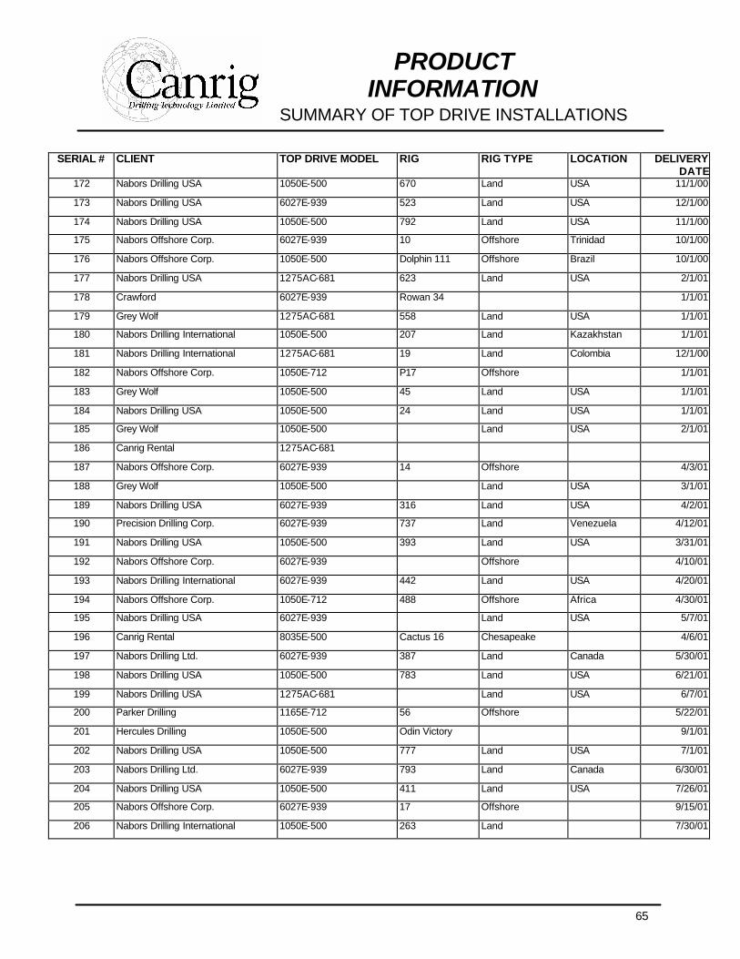
SUMMARY OF TOP DRIVE INSTALLATIONS
SERIAL # CLIENT TOP DRIVE MODEL RIG RIG TYPE LOCATION DELIVERY DATE
172 Nabors Drilling USA 1050E-500 670 Land USA 11/1/00
173 Nabors Drilling USA 6027E-939 523 Land USA 12/1/00
174 Nabors Drilling USA 1050E-500 792 Land USA 11/1/00
175 Nabors Offshore Corp. 6027E-939 10 Offshore Trinidad 10/1/00
176 Nabors Offshore Corp. 1050E-500 Dolphin 111 Offshore Brazil 10/1/00
177 Nabors Drilling USA 1275AC-681 623 Land USA 2/1/01
178 Crawford 6027E-939 Rowan 34 1/1/01
179 Grey Wolf 1275AC-681 558 Land USA 1/1/01
180 Nabors Drilling International 1050E-500 207 Land Kazakhstan 1/1/01
181 Nabors Drilling International 1275AC-681 19 Land Colombia 12/1/00
182 Nabors Offshore Corp. 1050E-712 P17 Offshore 1/1/01
183 Grey Wolf 1050E-500 45 Land USA 1/1/01
184 Nabors Drilling USA 1050E-500 24 Land USA 1/1/01
185 Grey Wolf 1050E-500 Land USA 2/1/01
186 Canrig Rental 1275AC-681
187 Nabors Offshore Corp. 6027E-939 14 Offshore 4/3/01
188 Grey Wolf 1050E-500 Land USA 3/1/01
189 Nabors Drilling USA 6027E-939 316 Land USA 4/2/01
190 Precision Drilling Corp. 6027E-939 737 Land Venezuela 4/12/01
191 Nabors Drilling USA 1050E-500 393 Land USA 3/31/01
192 Nabors Offshore Corp. 6027E-939 Offshore 4/10/01
193 Nabors Drilling International 6027E-939 442 Land USA 4/20/01
194 Nabors Offshore Corp. 1050E-712 488 Offshore Africa 4/30/01
195 Nabors Drilling USA 6027E-939 Land USA 5/7/01
196 Canrig Rental 8035E-500 Cactus 16 Chesapeake 4/6/01
197 Nabors Drilling Ltd. 6027E-939 387 Land Canada 5/30/01
198 Nabors Drilling USA 1050E-500 783 Land USA 6/21/01
199 Nabors Drilling USA 1275AC-681 Land USA 6/7/01
200 Parker Drilling 1165E-712 56 Offshore 5/22/01
201 Hercules Drilling 1050E-500 Odin Victory 9/1/01
202 Nabors Drilling USA 1050E-500 777 Land USA 7/1/01
203 Nabors Drilling Ltd. 6027E-939 793 Land Canada 6/30/01
204 Nabors Drilling USA 1050E-500 411 Land USA 7/26/01
205 Nabors Offshore Corp. 6027E-939 17 Offshore 9/15/01
206 Nabors Drilling International 1050E-500 263 Land 7/30/01
66
PRODUCT INFORMATION
SUMMARY OF TOP DRIVE INSTALLATIONS
SERIAL # CLIENT TOP DRIVE MODEL RIG RIG TYPE LOCATION DELIVERY DATE
207 Nabors Drilling USA 1050E-500 92 Land USA 8/6/01
208 Nabors Drilling USA 1275AC-681 623 Land USA 9/14/01
209 Parker Drilling 1165E-712 2 Speed 249 Land Kazakhstan 10/22/01
210 Nabors Drilling USA 6027E-939 227 Land USA 8/24/01
211 Nabors Alaska Drilling 6027E-939 2SE Alaska 9/26/01
212 Nabors Drilling USA 1275AC-681 Land USA 10/6/01
213 Nabors Offshore Corp. 6027E-939 Offshore 9/12/01
214 Grey Wolf 1275AC-681 Land USA 9/26/01
215 Nabors Drilling USA 1050E-500 Land USA 9/24/01
216 Nabors Drilling International 1050E-500 Land 10/12/01
217 Nabors Drilling USA 1050E-500 Land USA 10/18/01
218 Parker Drilling 1165E-2sp 258 Land Kazakhstan 11/7/01
219 Canrig Rental 6027E-939
220 Nabors Drilling USA 6027E-939 Land USA 11/22/01
221 Nabors Drilling USA 1050E-500 Land USA 12/10/01
222 Enafor 8035E-500 19 Land Algeria 4/02
223 AET 1050E-500 Land China 7/02
224 Enafor 8035E-500 20 Land Algeria 5/15/22
225 Gasprom 6027E-939 Land Russia 8/02
226 Gasprom 6027E-939 Land Russia 8/02
227 Nabors Drilling International 8035E-500 221 Land Yemen 7/02
228 Inventory 6027E-939
229 Nabors Drilling International 1250AC-712 16 Land Canada 9/02
230 Nabors Drilling International 1250AC-712 17 Land Canada 11/02
231 Parker Drilling 1165E-712 54B Land Louisiana 12/02
232 Rosneft 6027E-939 Land Russia 12/15/02
233 Rosneft 6027E-939 Land Russia 12/15/02
234 Rosneft 6027E-939 Land Russia 1/19/03
235 Rosneft 6027E-939 Land Russia 1/19/03
236 Yukos 8035E-500 Land Russia 1/28/03
237 Yukos 8035E-500 Land Russia 1/28/03
238 Inventory 6027-939
239 Inventory 1050E-500
240 Nabors Drilling International 6027AC-939 Land Canada
241 Enafor 8035-500 20 Land Algeria 03/03
67
PRODUCT INFORMATION
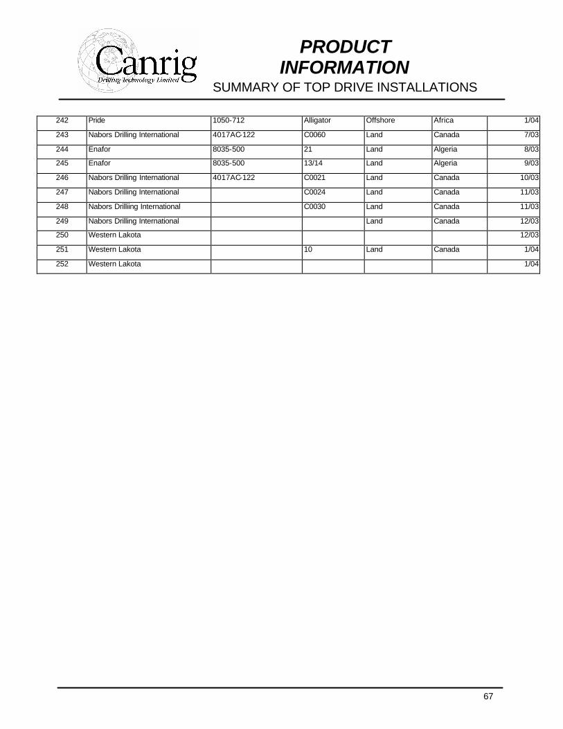
SUMMARY OF TOP DRIVE INSTALLATIONS
242 Pride 1050-712 Alligator Offshore Africa 1/04
243 Nabors Drilling International 4017AC-122 C0060 Land Canada 7/03
244 Enafor 8035-500 21 Land Algeria 8/03
245 Enafor 8035-500 13/14 Land Algeria 9/03
246 Nabors Drilling International 4017AC-122 C0021 Land Canada 10/03
247 Nabors Drilling International C0024 Land Canada 11/03
248 Nabors Drilliing International C0030 Land Canada 11/03
249 Nabors Drilling International Land Canada 12/03
250 Western Lakota 12/03
251 Western Lakota 10 Land Canada 1/04
252 Western Lakota 1/04