cam system design - west virginia...
TRANSCRIPT
Cam System Design

MAE 342 – Kinematics & Dynamics of Machinery
Typical Problem• Design a cam system to:
1. Open a valve 0.05 inches in 0.0025 seconds2. Stay open for 0.0050 seconds3. Close in 0.0025 seconds, and 4. Stay closed for 0.02 seconds.5. Repeat continuously.
2
0.05
y (in)
t (s)0
0 0.001
0.0025 0.0075
0.002 0.003
• Use a roller follower.
• Make accelerations as small as possible.
0.0325
MAE 342 – Kinematics & Dynamics of Machinery 3
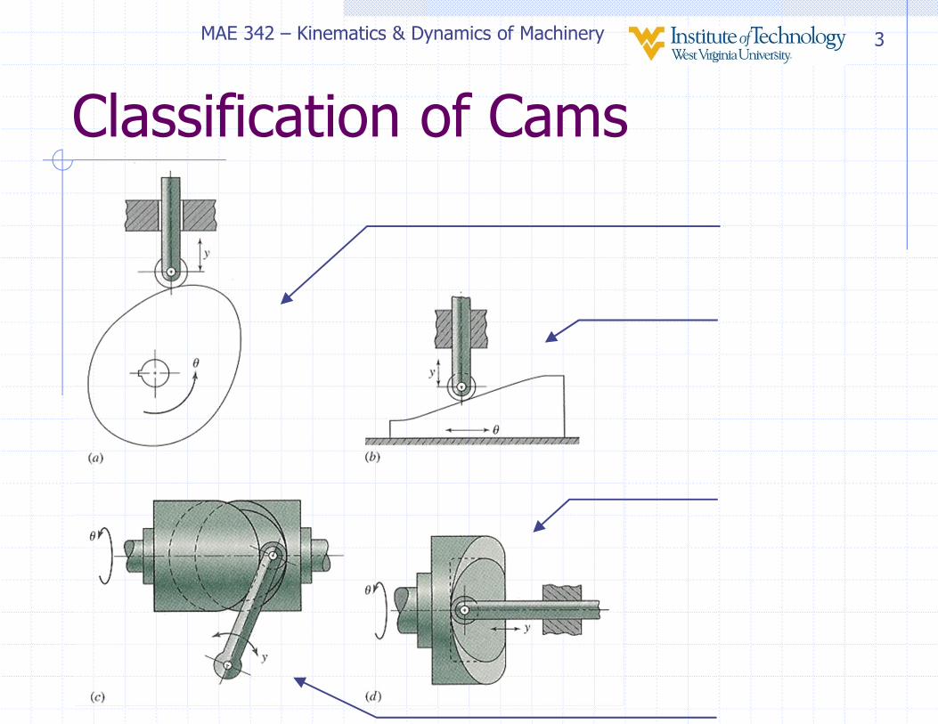
Classification of Cams
MAE 342 – Kinematics & Dynamics of Machinery 4
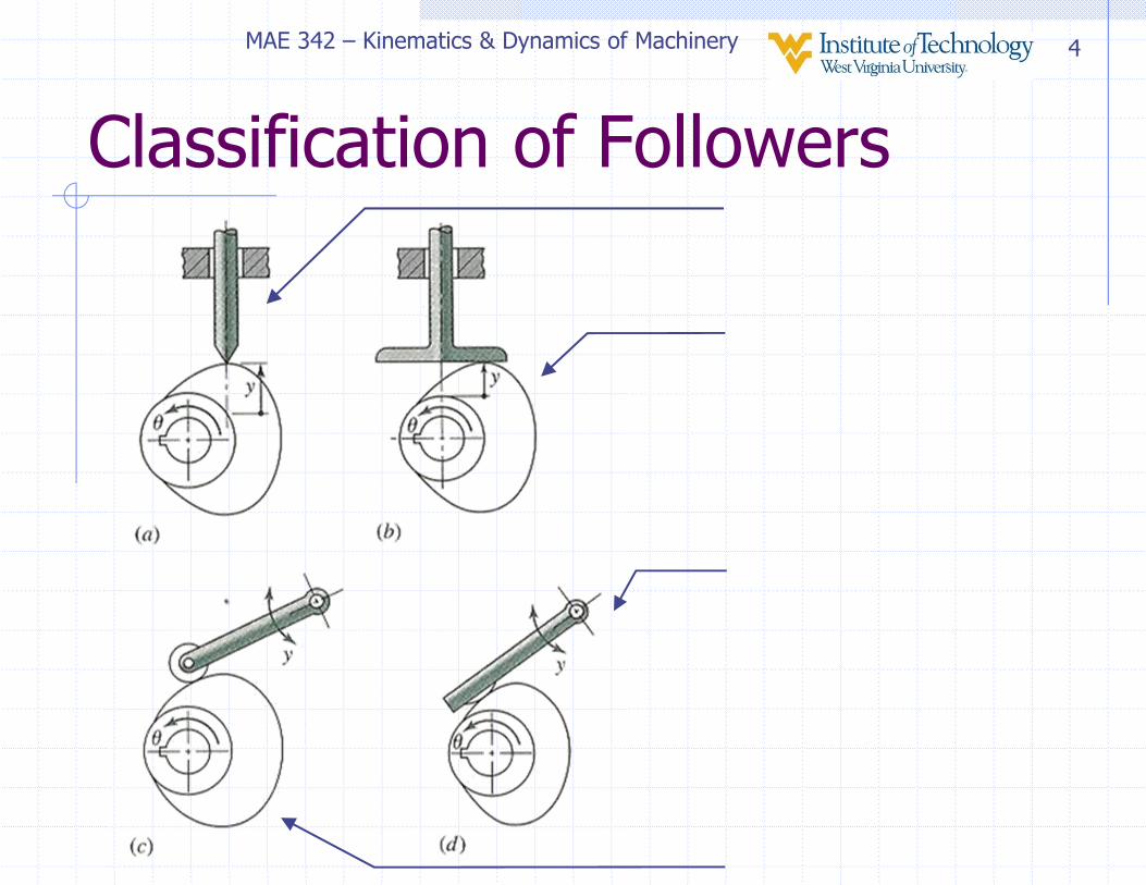
Classification of Followers
MAE 342 – Kinematics & Dynamics of Machinery 5
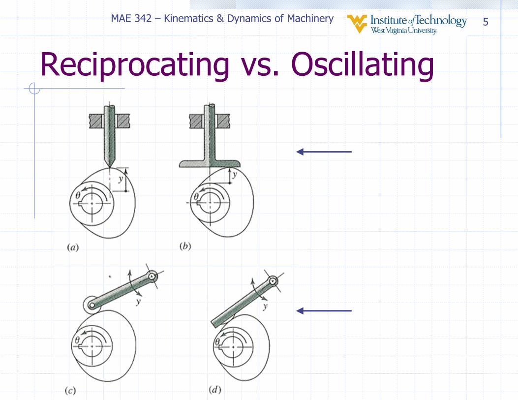
Reciprocating vs. Oscillating

MAE 342 – Kinematics & Dynamics of Machinery 6
Offset vs. Radial Follower

MAE 342 – Kinematics & Dynamics of Machinery 7
Mechanical Constraint Cam Systems
Ducati desmodromic camImage from MECH 324 Colorado State University
MAE 342 – Kinematics & Dynamics of Machinery 8
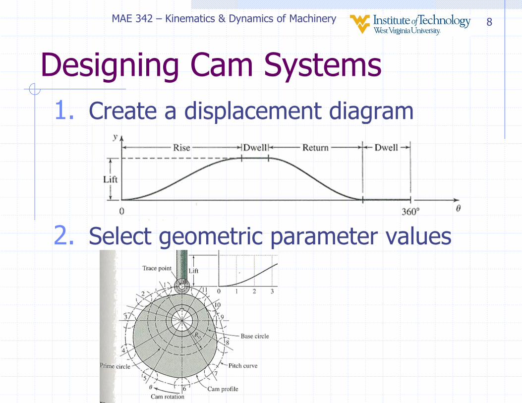
Designing Cam Systems
1. Create a displacement diagram
2. Select geometric parameter values

MAE 342 – Kinematics & Dynamics of Machinery 9
Creating Displacement Diagram
• Lift and dwell are usually application-dependent (given by application requirements)
• Therefore mainly need to design transitions:� Full-rise
� Half-rise
� Full-return
� Half-return
MAE 342 – Kinematics & Dynamics of Machinery 10
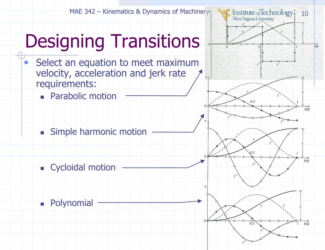
Designing Transitions• Select an equation to meet maximum
velocity, acceleration and jerk rate requirements:
� Parabolic motion
� Simple harmonic motion
� Cycloidal motion
� Polynomial

MAE 342 – Kinematics & Dynamics of Machinery 11
Selecting Geometric Parameters
• Geometric parameter values need to be chosen to avoid problems such as:
� Interference/undercuts
� High pressure angles
� Large enough face on follower
MAE 342 – Kinematics & Dynamics of Machinery 12
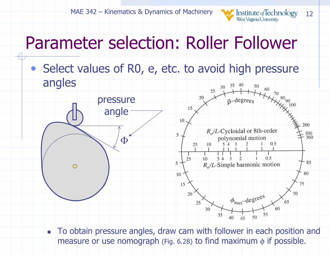
• Select values of R0, e, etc. to avoid high pressure angles
� To obtain pressure angles, draw cam with follower in each position and measure or use nomograph (Fig. 6.28) to find maximum φ if possible.
Parameter selection: Roller Follower
Φ
pressure angle
MAE 342 – Kinematics & Dynamics of Machinery 13
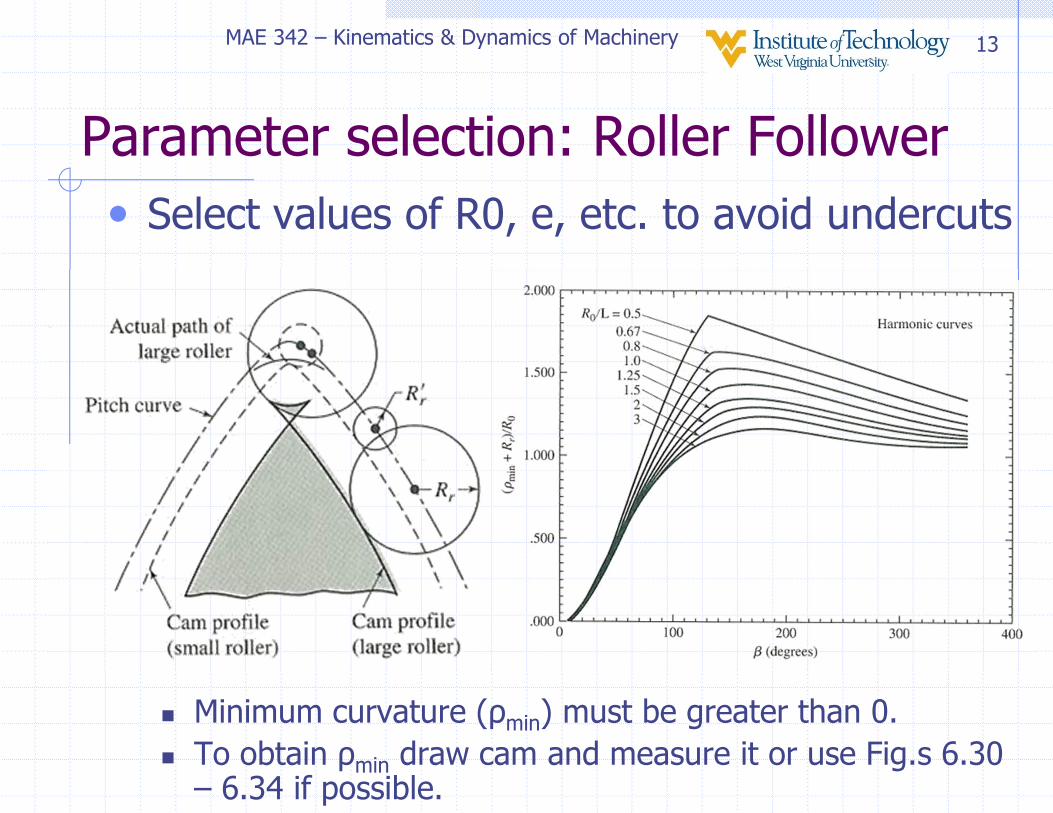
Parameter selection: Roller Follower
• Select values of R0, e, etc. to avoid undercuts
� Minimum curvature (ρmin) must be greater than 0.
� To obtain ρmin draw cam and measure it or use Fig.s 6.30 – 6.34 if possible.
MAE 342 – Kinematics & Dynamics of Machinery 14
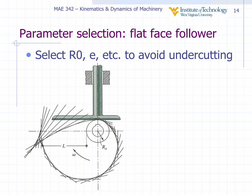
Parameter selection: flat face follower
• Select R0, e, etc. to avoid undercutting

MAE 342 – Kinematics & Dynamics of Machinery 15
Parameter selection: flat face follower
• Select face size & position so that face stays on cam