cam cephe teknik bilgi
TRANSCRIPT
HELSINKI UNIVERSITY OF TECHNOLOGY
Department of Civil and Environmental EngineeringLaboratory of Steel Structures
TEKNILLINEN KORKEAKOULU
Rakennus- ja ympäristötekniikan osastoTeräsrakennetekniikan laboratorio
Jussi Kallioniemi
JOINTS AND FASTENINGS IN STEEL-GLASS FACADES
Diplomityö on jätetty opinnäytteenä tarkastettavaksi diplomi-insinöörin tutkintoa varten
Espoossa 3.11.1999
Työn valvoja Professori TkT Pentti Mäkeläinen
Työn ohjaaja Professor Dr.-Ing. habil. Hartmut Pasternak
HELSINKI UNIVERSITYOF TECHNOLOGY
ABSTRACT OF THEMASTER´S THESIS
Author:Title of the thesis:Finnish title:
Jussi KallioniemiJoint and Fastenings in Steel-Glass FacadesLiitokset teräs-lasijulkisivuissa
Date: November 3rd 1999 Pages: 83+8
Civil and EnvironmentalEngineering
Professorship: Steel StructuresDepartment:
Supervisor:Instructor:
Professor D. Sc. (Tech.) Pentti MäkeläinenProfessor Dr.-Ing. habil. Hartmut Pasternak, BrandenburgTechnical University of Cottbus, Germany
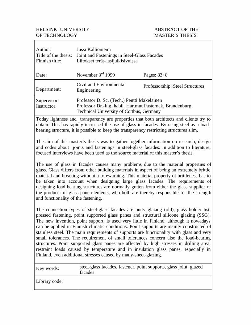
Today lightness and transparency are properties that both architects and clients try toobtain. This has rapidly increased the use of glass in facades. By using steel as a load-bearing structure, it is possible to keep the transparency restricting structures slim.
The aim of this master’s thesis was to gather together information on research, designand codes about joints and fastenings in steel-glass facades. In addition to literature,focused interviews have been used as the source material of this master’s thesis.
The use of glass in facades causes many problems due to the material properties ofglass. Glass differs from other building materials in aspect of being an extremely brittlematerial and breaking without a forewarning. This material property of brittleness has tobe taken into account when designing large glass facades. The requirements ofdesigning load-bearing structures are normally gotten from either the glass supplier orthe producer of glass pane elements, who both are thereby responsible for the strengthand functionality of the fastening.
The connection types of steel-glass facades are putty glazing (old), glass holder list,pressed fastening, point supported glass panes and structural silicone glazing (SSG).The new invention, point support, is used very little in Finland, although it nowadayscan be applied in Finnish climatic conditions. Point supports are mainly constructed ofstainless steel. The main requirements of supports are functionality with glass and verysmall tolerances. The requirement of small tolerances concern also the load-bearingstructures. Point supported glass panes are affected by high stresses in drilling area,restraint loads caused by temperature and in insulation glass panes, especially inFinland, even additional stresses caused by many-sheet-glazing.
Key words: steel-glass facades, fastener, point supports, glass joint, glazedfacades
Library code:
TEKNILLINEN KORKEAKOULU DIPLOMITYÖN TIIVISTELMÄ
Tekijä:Työn nimi:English title:
Jussi KallioniemiLiitokset teräs-lasijulkisivuissaJoint and Fastenings in Steel-Glass Facades
Päivämäärä: 3.11.1999 SSivumäärä: 83+8
Rakennus- ja ympäristö-tekniikan osasto PProfessuuri: TeräsrakennetekniikkaOsasto:
Työn valvoja:Työn ohjaaja:
Professori TkT Pentti MäkeläinenProfessor Dr.-Ing. habil. Hartmut Pasternak, BrandenburgTechnical University of Cottbus, Saksa
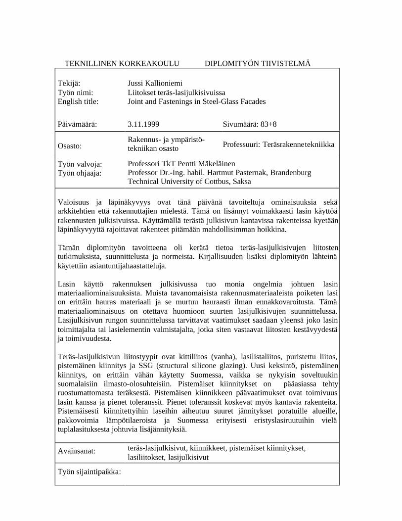
Valoisuus ja läpinäkyvyys ovat tänä päivänä tavoiteltuja ominaisuuksia sekäarkkitehtien että rakennuttajien mielestä. Tämä on lisännyt voimakkaasti lasin käyttöärakennusten julkisivuissa. Käyttämällä terästä julkisivun kantavissa rakenteissa kyetäänläpinäkyvyyttä rajoittavat rakenteet pitämään mahdollisimman hoikkina.
Tämän diplomityön tavoitteena oli kerätä tietoa teräs-lasijulkisivujen liitostentutkimuksista, suunnittelusta ja normeista. Kirjallisuuden lisäksi diplomityön lähteinäkäytettiin asiantuntijahaastatteluja.
Lasin käyttö rakennuksen julkisivussa tuo monia ongelmia johtuen lasinmateriaaliominaisuuksista. Muista tavanomaisista rakennusmateriaaleista poiketen lasion erittäin hauras materiaali ja se murtuu hauraasti ilman ennakkovaroitusta. Tämämateriaaliominaisuus on otettava huomioon suurten lasijulkisivujen suunnittelussa.Lasijulkisivun rungon suunnittelussa tarvittavat vaatimukset saadaan yleensä joko lasintoimittajalta tai lasielementin valmistajalta, jotka siten vastaavat liitosten kestävyydestäja toimivuudesta.
Teräs-lasijulkisivun liitostyypit ovat kittiliitos (vanha), lasilistaliitos, puristettu liitos,pistemäinen kiinnitys ja SSG (structural silicone glazing). Uusi keksintö, pistemäinenkiinnitys, on erittäin vähän käytetty Suomessa, vaikka se nykyisin soveltuukinsuomalaisiin ilmasto-olosuhteisiin. Pistemäiset kiinnitykset on pääasiassa tehtyruostumattomasta teräksestä. Pistemäisen kiinnikkeen päävaatimukset ovat toimivuuslasin kanssa ja pienet toleranssit. Pienet toleranssit koskevat myös kantavia rakenteita.Pistemäisesti kiinnitettyihin laseihin aiheutuu suuret jännitykset poratuille alueille,pakkovoimia lämpötilaeroista ja Suomessa erityisesti eristyslasiruutuihin vielätuplalasituksesta johtuvia lisäjännityksiä.
Avainsanat: teräs-lasijulkisivut, kiinnikkeet, pistemäiset kiinnitykset,lasiliitokset, lasijulkisivut
Työn sijaintipaikka:

1
Preface
This master’s thesis has been written at Helsinki University of Technology, in the
Laboratory of Steel Structures of the Department of Civil and Environmental
Engineering, with financial support from the Laboratory of Steel Structures, The
Finnish Constructional Steelwork Association (FSCA), STALA Oy and
Rautaruukki Oyj.
Many people have contributed to this work. Warm thanks are due to all of them
for their cooperation and advice. I thank Professor Pentti Mäkeläinen for
supervising this research and Professor Dr.-Ing. habil. Hartmut Pasternak
(Brandenburg Technical University of Cottbus, Germany) for his help in Germany
as the instructor of this thesis. I also thank the researchers and other staff of the
Laboratory of Steel Structures for their valuable aid and time of which I
incessantly (and shamelessly) have used.
Furthermore, I thank my family for support and Mette for encouragement and
tireless help on correcting my language.
Espoo, November 3rd 1999
Jussi Kallioniemi
2
CONTENTS
ABSTRACT
TIIVISTELMÄ
PREFACE………………………………………………………………………...1
CONTENTS………………………………………………………………………2
SYMBOLS AND ABBREVIATIONS…………………………………………..4
1 INTRODUCTION......................................................................................... 5
2 STEEL-GLASS STRUCTURES IN FACADES ........................................ 6
2.1 GENERAL...................................................................................................... 6
2.2 COMPONENTS OF STEEL-GLASS STRUCTURES .............................................. 7
2.3 MATERIAL PROPERTIES ................................................................................ 9
2.3.1 In General............................................................................................ 9
2.3.2 Glass.................................................................................................. 10
2.3.3 Steel ................................................................................................... 14
2.3.4 Stainless Steel .................................................................................... 14
2.3.5 Aluminium ......................................................................................... 15
2.4 CODES AND STANDARDS............................................................................ 15
2.4.1 Eurocodes.......................................................................................... 15
2.4.2 German Codes................................................................................... 16
2.4.3 Finnish Codes.................................................................................... 19
3 STEEL-GLASS FACADES........................................................................ 27
3.1 IN GENERAL............................................................................................... 27
3.2 SUPPORTING STEEL STRUCTURES ............................................................... 27
3.2.1 Conventional Supporting Structures ................................................. 27
3.2.2 Hybrid-Supported Structures ............................................................ 29
3.2.3 Supporting Cable Mechanism ........................................................... 33
3.2.4 Double Face Facades........................................................................ 38
3.3 FIRE SAFETY OF STEEL-GLASS STRUCTURES ............................................. 40
4 FASTENINGS AND JOINTS IN STEEL-GLASS FACADES............... 42
3
4.1 IN GENERAL............................................................................................... 42
4.2 MECHANICAL FASTENING.......................................................................... 43
4.2.1 Putty Glazing..................................................................................... 43
4.2.2 Glass Holder List............................................................................... 44
4.2.3 Pressed Fastening ............................................................................. 46
4.2.4 Point Supported Glass Panes............................................................ 48
4.3 STRUCTURAL SILICONE GLAZING............................................................... 64
4.3.1 In General.......................................................................................... 64
4.3.2 Loads ................................................................................................. 65
4.3.3 Silicone.............................................................................................. 69
4.3.4 Safety of Structural Glazing .............................................................. 70
5 CONCLUSIONS.......................................................................................... 74
REFERENCES………………………………………………………………….76
APPENDICES:
APPENDIX A
APPENDIX B
4
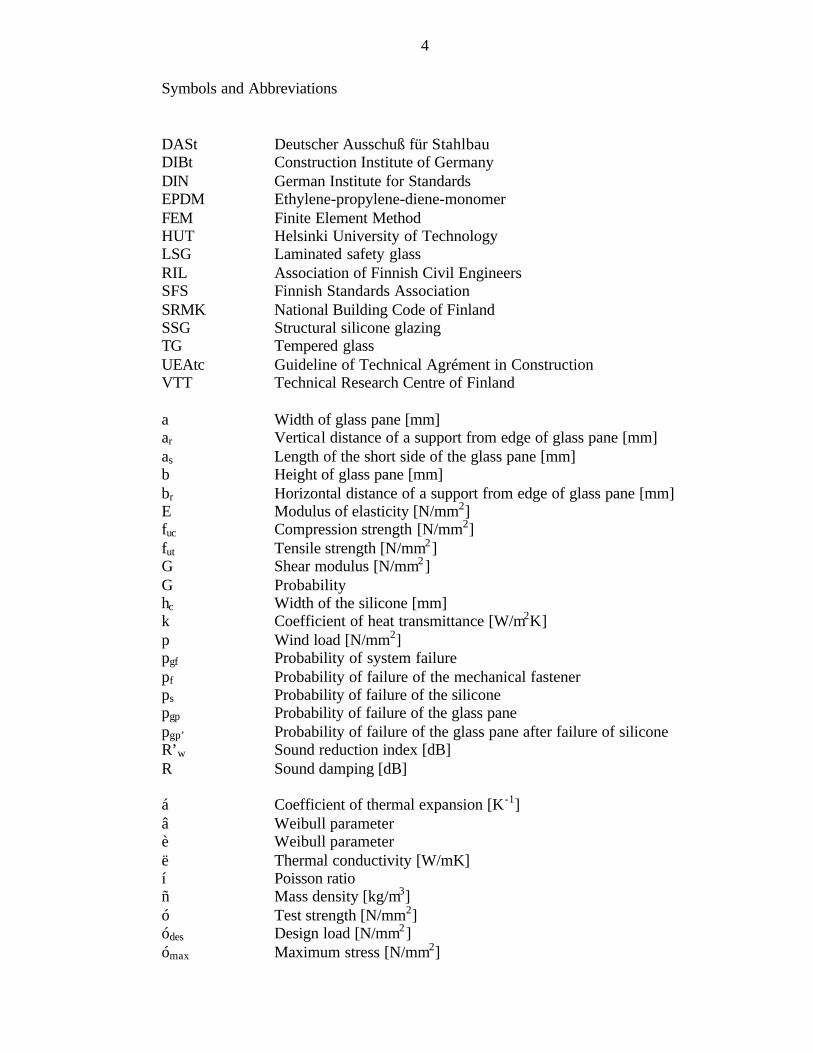
Symbols and Abbreviations
DASt Deutscher Ausschuß für StahlbauDIBt Construction Institute of GermanyDIN German Institute for StandardsEPDM Ethylene-propylene-diene-monomerFEM Finite Element MethodHUT Helsinki University of TechnologyLSG Laminated safety glassRIL Association of Finnish Civil EngineersSFS Finnish Standards AssociationSRMK National Building Code of FinlandSSG Structural silicone glazingTG Tempered glassUEAtc Guideline of Technical Agrément in ConstructionVTT Technical Research Centre of Finland
a Width of glass pane [mm]ar Vertical distance of a support from edge of glass pane [mm]as Length of the short side of the glass pane [mm]b Height of glass pane [mm]br Horizontal distance of a support from edge of glass pane [mm]E Modulus of elasticity [N/mm2]fuc Compression strength [N/mm2]fut Tensile strength [N/mm2]G Shear modulus [N/mm2]G Probabilityhc Width of the silicone [mm]k Coefficient of heat transmittance [W/m2K]p Wind load [N/mm2]pgf Probability of system failurepf Probability of failure of the mechanical fastenerps Probability of failure of the siliconepgp Probability of failure of the glass panepgp’ Probability of failure of the glass pane after failure of siliconeR’w Sound reduction index [dB]R Sound damping [dB]
á Coefficient of thermal expansion [K-1]â Weibull parameterè Weibull parameterë Thermal conductivity [W/mK]í Poisson ratioñ Mass density [kg/m3]ó Test strength [N/mm2]ódes Design load [N/mm2]ómax Maximum stress [N/mm2]

5
1 INTRODUCTION
Glass has become a major architectural element over the last years. Modern
architecture demands light structures and high transparency of facades.
Technology and engineers have to find answers to this demand. When using steel
as a load-bearing structure and glass as a covering structure high transparency
with sufficient safety is achievable. In Central Europe, especially in Germany, this
topic is under great interest. In the beginning of the 1990’s Technical Research
Centre of Finland (VTT) conducted a wide research about glazed roof and wall
structures [1, 2, 3, 4, 5]. After that any similar researches have not been
performed.
The aim of this master’s thesis is to gather together known new information about
steel-glass facades. One of the main objects is supporting structures of steel-glass
facades. Another one is connections between steel and glass in steel-glass facades.
In this thesis facts that are already known about the construction of steel-glass
facades are written. In addition, unknown or not yet researched information that
should still be studied is introduced. This thesis should be a source for further
research.
The author spent two months at Brandenburg Technical University of Cottbus in
Germany collecting literature about the subject. Therefore literature from mainly
Germany and Finland is used in this thesis. In addition to literature, focused
interviews have been used as the source material of this master’s thesis.
This master’s thesis has been illustrated with one example in which a glass
building, the New Leipzig Fair, has been examined.
6
2 STEEL-GLASS STRUCTURES IN FACADES
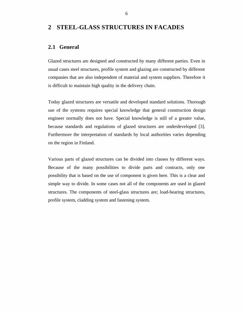
2.1 General
Glazed structures are designed and constructed by many different parties. Even in
usual cases steel structures, profile system and glazing are constructed by different
companies that are also independent of material and system suppliers. Therefore it
is difficult to maintain high quality in the delivery chain.
Today glazed structures are versatile and developed standard solutions. Thorough
use of the systems requires special knowledge that general construction design
engineer normally does not have. Special knowledge is still of a greater value,
because standards and regulations of glazed structures are underdeveloped [3].
Furthermore the interpretation of standards by local authorities varies depending
on the region in Finland.
Various parts of glazed structures can be divided into classes by different ways.
Because of the many possibilities to divide parts and contracts, only one
possibility that is based on the use of component is given here. This is a clear and
simple way to divide. In some cases not all of the components are used in glazed
structures. The components of steel-glass structures are; load-bearing structures,
profile system, cladding system and fastening system.

7
2.2 Components of Steel-Glass Structures [3]
Figure 1 . Components of steel-glass structuresBild 1. Bauteilen von Stahl-Glas Konstruktionen
Load-bearing Frame Structures
Load-bearing frame structures are the load-bearing and load transferring part of
glazed structures. Load-bearing frame structures bear and transfer the loads from
covering glass and from the parts that are connected to the covering glass to the
other load-bearing structures of the building. Therefore the primary requirement
of frame structure is strength. Other necessary structural requirements that need to
be considered are for example thermal expansion, fire resistance and fracture
behaviour. Frame structures are often not needed in glazed structures with a short
span and especially with a short span in vertical position. If frame structures are
needed, then usually tubular steel beams and columns are used because of their
good fastening properties. Steel structures generally have to be fire protected,
which is then normally done by fire protection paints.
Profile System
Profile system is the part that the cladding system is connected to. The primary
function of the profile system is to transfer loads from the cladding system to the
1. Load-bearing
structures
2. Profile system
3. Cladding system
4. Fastening system

8
load-bearing frame structures. Together profile and cladding systems constitute a
coherent close structure, a so called light shell. Traditionally profile systems have
been versatile aluminium structures that in principle can be used in all kinds of
joints and structures. Nowadays profile systems are constructed also from
stainless steel or plastic. In some cases they are even left completely out. If they
are not used, the cladding system is connected straight to the load-bearing frame
structures. This is so called structural glazing.
Cladding System
The primary function of the cladding system is to work as a covering structure and
to protect the structure inside from environmental effects while letting light come
through. Special assignments like thermal and sound insulation, fire resistance and
safety can be imposed on this protection function. Resisting or penetrating other
than visible light wavelength can also be an essential task. Various glasses are
normally used as a light-penetrating material in facades.
Fastening System
Fastening system is used to attach the light shell to the surrounding shell. The
function of the fastening unit is to be a part of the shell and accomplish the
required tightness, thermal insulation, appearance and other possible demands. In
a wider sense, fastening unit consists of different kinds of heightening and fitting
solutions made for glass structures.
Other Systems
Because of the needs of the user there are other possible factors that have to be
taken care of in design, fabrication and installation of steel-glass facades. These
are for example opening, service, shading and operation systems of the windows.
In Table 1 all requirements for glazed structures are listed.
9
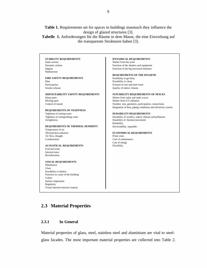
Table 1. Requirements set for spaces in buildings inasmuch they influence thedesign of glazed structures [3].
Tabelle 1. Anforderungen für die Räume in dem Masse, die eine Einwirkung aufdie transparente Strukturen haben [3].
2.3 Material Properties
2.3.1 In General
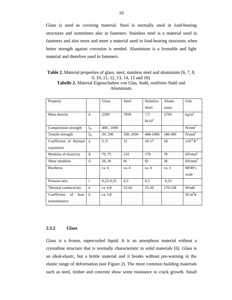
Material properties of glass, steel, stainless steel and aluminium are vital to steel-
glass facades. The most important material properties are collected into Table 2.
STABILITY REQUIREMENTS DYNAMICAL REQUIREMENTSStatic actions Shelter from the windDynamic actions Function of the shutters and equipmentImpacts Function of the big structural elementsMalfunction
REQUIREMENTS OF THE HYGIENEFIRE SAFETY REQUIREMENTS Possibility to get dirtyHeat Possibility to cleanParticipation Exhaust of rain and melt waterSmoke exhaust Quality of indoor climate
SERVICEABILITY SAFETY REQUIREMENTS SUITABILITY REQUIREMENTS OF SPACESSharp parts Shelter from radar and radio waves Moving parts Shelter from UV-radiationControl of transit Number, size, geometry, participation, connections
Integration of heat, piping ventilation and electricity systemREQUIREMENTS OF TIGHTNESSTightness of raining water DURABILITY REQUIREMENTSTightness of extinguishing water Durability of weather, indoor climate and pollutants Airtightness Durability of thermal movement
ReliabilityREQUIREMENTS OF THERMAL HUMIDITY Serviceability, reparableTemperature of airThermal heat radiation ECONOMICAL REQUIREMENTSAir flow, draught Prime costsCondensation Cost of maintenance
Cost of energyACOUSTICAL REQUIREMENTS FlexibilityExternal noiseInternal noiseReverberation
VISUAL REQUIREMENTSIlluminanceGlarePossibility to darkenFunction as a part of the buildingColourSurface impressionRegularityVisual internal-external contacts
10
Glass is used as covering material. Steel is normally used in load-bearing
structures and sometimes also in fasteners. Stainless steel is a material used in
fasteners and also more and more a material used in load-bearing structures when
better strength against corrosion is needed. Aluminium is a formable and light
material and therefore used in fasteners.
Table 2. Material properties of glass, steel, stainless steel and aluminium [6, 7, 8,9, 10, 11, 12, 13, 14, 15 and 16].
Tabelle 2. Material Eigenschaften von Glas, Stahl, rostfreier Stahl undAluminium.
Property Glass Steel Stainless
Steel
Alumi-
nium
Unit
Mass density ñ 2500 7850 7,7-
8x10³
2700 kg/m3
Compression strength fuc 400...1000 N/mm2
Tensile strength fut 20..100 350..1050 448-1966 180-300 N/mm2
Coefficient of thermal
expansion
á 5..9 12 10-17 24 x10-6 K-1
Modulus of elasticity E 70..75 210 170 70 kN/mm2
Shear modulus G 28..30 81 65 26 kN/mm2
Hardness ca. 6 ca. 4 ca. 4 ca. 3 MOH’s
scale
Poisson ratio í 0,22-0,25 0,3 0,3 0,33
Thermal conductivity ë ca. 0,8 52-65 15-30 170-238 W/mK
Coefficient of heat
transmittance
k ca. 5,8 W/m2K
2.3.2 Glass
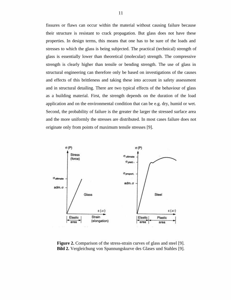
Glass is a frozen, supercooled liquid. It is an amorphous material without a
crystalline structure that is normally characteristic to solid materials [6]. Glass is
an ideal-elastic, but a brittle material and it breaks without pre-warning in the
elastic range of deformation (see Figure 2). The more common building materials
such as steel, timber and concrete show some resistance to crack growth. Small
11
fissures or flaws can occur within the material without causing failure because
their structure is resistant to crack propagation. But glass does not have these
properties. In design terms, this means that one has to be sure of the loads and
stresses to which the glass is being subjected. The practical (technical) strength of
glass is essentially lower than theoretical (molecular) strength. The compressive
strength is clearly higher than tensile or bending strength. The use of glass in
structural engineering can therefore only be based on investigations of the causes
and effects of this brittleness and taking these into account in safety assessment
and in structural detailing. There are two typical effects of the behaviour of glass
as a building material. First, the strength depends on the duration of the load
application and on the environmental condition that can be e.g. dry, humid or wet.
Second, the probability of failure is the greater the larger the stressed surface area
and the more uniformly the stresses are distributed. In most cases failure does not
originate only from points of maximum tensile stresses [9].
Figure 2. Comparison of the stress-strain curves of glass and steel [9].Bild 2. Vergleichung von Spannungskurve des Glases und Stahles [9].
12
Because of their ductile behaviour, common building materials are very tolerant to
high local stresses and discontinuities in their support; this means that steel
assemblies can be rigidly bolted since some plastic flows in the material will
relieve any high stresses that may occur. None of this is true with glass, as any
stresses or distortion that exceeds the linear strength will cause brittle failure. In
traditional glass construction this problem has been solved by adding a flexible
and absorbing substance, such as a rubber seal or pad, between the glass and its
support.
The new approach in the construction of steel-glass structures is different. The
support system is conceived so that there is always a clear analysable load path.
The stresses in the glass have been very precisely predicted under all load
conditions. The design of the spherical bearing assemblies at the glass support
points and of the compressed spring support system are two examples of the
application of these principles. The requirements for predictable behaviour under
load were used in a positive way to express the inherent physical characteristics of
the glass and to enhance the transparency and lightness on the whole.
To counter the fragility of glass, the industry has developed a number of methods
to strengthen it. These do not change its nature, but neither do they raise the
threshold at which cracking occurs, or incorporate additional ductile materials that
absorb the energy and therefore prevent total failure when a unit has cracked.
Among these, the three most commonly used methods are the use of toughened or
tempered glass, laminated glass and wired glass. The information written in the
three paragraphs above is gathered from reference [17].
A modern method of estimating the strength of glass and designing glass
constructions is to use the fracture mechanics [18]. Especially the Weibull method
is used. In Germany design strength of ceramic materials is determined according
to DIN 52 292. Nowadays it is used also for glass. The design strength is based on
test results. Test strengths are put into the Weibull distribution which gives the
probability of failure. The equation is,
13
θσ−−=
β
exp1G (1)
where
G = Probabilityó = Test strengthè = Weibull parameterâ = Weibull parameter
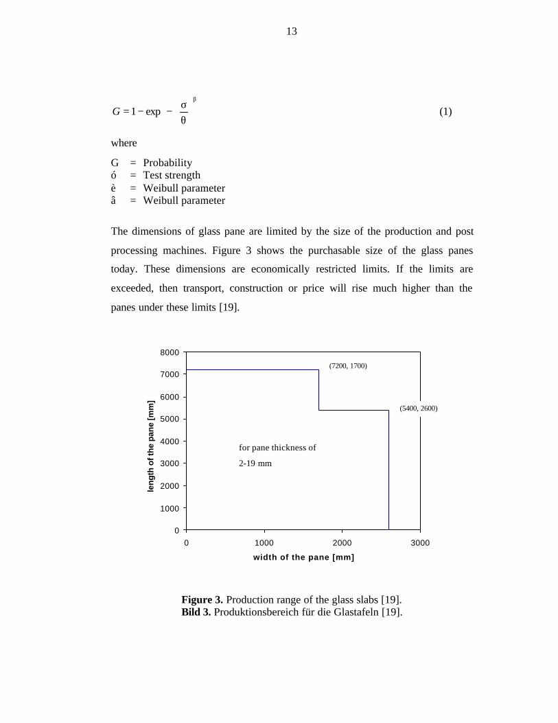
The dimensions of glass pane are limited by the size of the production and post
processing machines. Figure 3 shows the purchasable size of the glass panes
today. These dimensions are economically restricted limits. If the limits are
exceeded, then transport, construction or price will rise much higher than the
panes under these limits [19].
Figure 3. Production range of the glass slabs [19].Bild 3. Produktionsbereich für die Glastafeln [19].
0
1000
2000
3000
4000
5000
6000
7000
8000
0 1000 2000 3000
width of the pane [mm]
len
gth
of
the
pan
e [m
m]
for pane thickness of
2-19 mm
(7200, 1700)
(5400, 2600)
14
2.3.3 Steel
Joining steel to other construction materials has been an important part in the
development of constructing steels. Combining glass and steel has created the
most significant architectural achievements. The lightness of steel compared to its
strength has been the decisive aspect of using steel with glass.
In steel glass facades load-bearing steel structures are not hidden in the walls and
sometimes are also outside the building. Therefore they have to be protected from
corrosion. Because of structure’s visibility the decisive aspect is often appearance.
70 ìm zinc cover fulfils the requirements Finnish Standards Association (SFS)
2765 in class A [20]. As new, zinc is shiny and spotty but in time being it begins
to dim and change to gray.
Unprotected steel warms quickly and then looses its strength. A situation where
steel would last 30 minutes in fire cannot normally be achieved without fire
protection [20].
2.3.4 Stainless Steel
There are three basic types of stainless steel; martensitic, ferritic and austenic.
These are defined by the chemical composition of the alloy and by the treatment
the material has undergone. Most of the stainless steels used in buildings are
austenic steels, because they are easily formed and welded [17].
Stainless steel is often considered an expensive material. Long life span of
stainless steel and little need of service favours the use of it [20]. Stainless steel
does not corrode nor turn dark in outdoor climatic conditions. It contains lots of
chrome which creates a protective chrome dioxide coating. Therefore it does not
have to be covered with covering materials.
Stainless steel has a coefficient of thermal expansion two to three times bigger
than glass has. It is also one and a half times bigger than steel’s which might
15
create a need for more consideration in some cases when designing details,
especially in cases where stainless steel is acting as a load-bearing structure and
glass is supported only by point supports. These materials together might cause
more stresses to the joint area. Welding straight long unsymmetrical profiles like
T-or U-profiles is difficult because of the big coefficient of thermal expansion.
2.3.5 Aluminium
Aluminium is a light, corrosion resistant material that needs only a little service.
Its weight is only one third of steel’s and stainless steel’s but its strength is ca.
half of their strength. It is also easily formed and therefore ideal for window
frames and doors with long series. It is not very easily welded and therefore not
used for small series or individual cases. One problem with welding is the big
coefficient of thermal expansion. It is difficult to weld large forms and lists
without distortion. Normally all aluminium profiles are therefore extruded.
Aluminium has a long life span.
2.4 Codes and Standards
2.4.1 Eurocodes
There are three different class modelling types of structural concept in Eurocodes
[21]. It is presumed that the layout, shape and the structural concept has already
been chosen from first evaluations of the requirements for the expected use and
for safety against failure under the actions that may occur. This choice comprises
the types and position of
1. the main load-bearing systems including their spacings and dimensions, their
joints and connections and their foundations, the failure of which would
induce a collapse of the structure,
2. secondary structural elements as beams or purlins that transfer the loads to a
main system, a failure of which would lead to a collapse of these elements
without affecting the main frames,
16
3. other elements as for cladding, roofing, partitions or facades, that merely
transfer loads to main or secondary elements and the failure of which would
have minor consequences.
By far glass has been used primarily for panes. The panes are pure filling
elements and therefore glass is placed on the class 3. Nowadays more and more
glass is used also for construction elements in classes 1 and 2. The growing use of
glass as a load-bearing material requires new design rules that ensure security. It
should be added, however, that the present Eurocode system does not include such
a practically developed reliability differentiation scheme. In Eurocodes there are
no further design rules for glazed facades.
2.4.2 German Codes
2.4.2.1 In General
If glass is used as a load-bearing material according to section § 3 in public law
requires; ”it has to be constructed so that public safety and order especially life
and health will not be in danger.” [22]
DIN-codes are the regulations of technique. DIN-codes serve rationalisation,
quality assurance, safety, environmental protection and understanding in
economy, technique, science, administration and public. Legally DIN-codes are
not obligatory. This means DIN-codes can be used but not that they have to be.
On the other hand they are often made obligatory by contracts. The information
written above is from reference [23].
Construction Institute of Germany (DIBt) is an institute that accords European
technical permission to construction products [24]. It also does co-operation in
technical regulations (especially in codes) with national, European and
international field. Associates of DIBt work in many bodies of the DIN.
17
DASt has not published anything concerning steel-glass facades [25].
2.4.2.2 DIN-Codes
Steel-glass facades have to obey normal codes about building physics. Required
thermal insulation for buildings is defined in DIN 4108. Sound insulation
requirements are in DIN 4109 and required fire protection for the various
structures is written in DIN 4102.
There are several special codes for glass and constructing with glass. The parts
that concern steel-glass facades are written in this thesis. Other DIN codes that
involve glass are written in Appendix 1.
DIN 18 545 part 1: the ways to fasten the glass to the profile unit are defined. The
code is made only for normal glazing, not for break resistant, under water, fire
resistant or roof glazing. About designations, requirements and testing of
fastening materials are written in part two.
DIN 18516 Part 1, 4: for ventilated facades bending and the loads from wind
pressure, wind suction and wind push. There are also corrosion protection
provisions [26]. Part 4 is for one pane security glass. It defines an adequate
fastening with a required cover area of 1000 mm2 for structural sealant glazing. If
this requirement is not used the fitness of use must be proofed by tests. Due to the
scattering of the glass strength at least 10 tests are to be performed [27].
The following materials are allowed to be used in surface of facades without
supplementary corrosion protection [26]:
Stainless steel according to DIN 17 440, 17 441, 17 455 or 17 456
Aluminium according to DIN 4113 part 1, DIN 1745 part 1. DIN 1745 part 1
includes also several aluminium compounds.
Various steel grades according to DIN 18 800 part 1 DIN 17 162 part 2.
18
Regulations for various steel grades that need corrosion protection are in DIN 55
928 parts 5. E.g. minimum fire zinc coating is 350 g/m2 and with PVC-coating or
equivalent material minimum is 100 ìm.
Drilling edges of unalloyed steel thinwall surface have to be protected. Between
the head of the fastener and the steel sheet an elastomeric piece has to be installed.
The elastomeric piece shall not be damaged by tightening torque of screw.
The following materials are allowed to be used in inner structures in facades
without supplementary corrosion protection [26]:
Stainless steel according to DIN 17 440, 17 441, 17 455 or 17 456
Aluminium according to DIN 4113 part 1, DIN 1745 part 1. DIN 1745 part 1
includes also several aluminium compounds.
Steel grades according to DIN 18 800 part 1 need corrosion protection that is
written in DIN 55 928 part 1.
Qualifications of other corrosion protection systems (in surface or in inner
structures of facades) should be approved by an official material testing laboratory
(Material Prüfungsanstalt).
2.4.2.3 Construction Institute of Germany (DIBt)
In general there are no codes or instructions for especially steel-glass structures in
Germany, but for glazing there are regulations. Glazed structures are divided into
two different parts: regulated and non-regulated glazing. For regulated glazing the
instructions are given in “Technical regulations for line supported vertical
Glazing” [28] which is a report of DIBt. There are design instructions for line
supported vertical glazing. The report is valid for outer wall glazing that is
linearly supported by at least two opposite sides. It is not valid for;
- ventilated outer wall cover of toughened glass by DIN 18 516-4
- structural silicone glazing
- glazing with bent glass
- glazing that is mainly used for stiffening
19
- glazing that is protected against falling
- glazing that is weakened by drilling, piercing or edge cut.
The supporting structures are not handled in the report. There are also instructions
for horizontal glazing in another report [29].
For non-regulated glazing and glass structures, licence to construct has to be
applied from the head of the state construction authority (Oberste
Landesbaubehörde). E.g. there are not yet regulations concerning point supported
glass structures and therefore they are non-regulated glass structures. To get the
construction licence, ultimate limit states and serviceability limit states of
structures have to be researched by tests. The information written above can be
found in references [30, 31].
2.4.2.4 Other Guidelines
In Germany, many technical guidelines for glazing industry have been written for
glazing and windows. They are mainly for designing and constructing windows.
With the help of guidelines it is possible to e.g. design glass panes against wind
loads with maximum pane size of 8000 mm x 3180 mm and fasten the pane
frames and fasten glass to other materials. Glass roofs are also included in the
guidelines. The guidelines include a case of steel framed shop window and other
similar structures as special cases. The information above is gathered from the
guidelines which are written in references [32-46].
2.4.3 Finnish Codes
2.4.3.1 In General
Finnish Standard Association (SFS) is responsible for the collection of standards.
The standards should correspond to the needs of Finland and Finnish climate and
include the national standards that international and European agreements require
[47]. National Building Code of Finland (SRMK) gives supplementary technical
20
and corresponding regulations and guidelines for the building laws and decrees.
The regulations concern new constructions and they are obligatory. Other
technical solutions that are given in the guidelines can be used, if they fulfil the
requirements of the regulations that are applied for construction [48]. Association
of Finnish Civil Engineers (RIL) has published its own series of professional
standards, codes of practice and handbooks.
2.4.3.2 Finnish Standards Association (SFS) [6]
SFS standards for windows and glazed structures are being updated at the
moment. European standards are ready, but national committees still have to
confirm them. In SFS 3304, windows are divided into classes by their functional
and operational properties. There are requirements for airtightness, tightness of
raining water, wind pressure, sound damping and strength. There are different
standards for fittings, fastenings and glazing of windows.
2.4.3.3 National Building Code of Finland (SRMK)
In designing glazed structures different parts of SRMK are applied so that all
requirements are fulfilled and glazed structures achieve a certain limit of safety.
There are no codes exclusively for safety or strength of glazed structures in
SRMK [6].
Thermal insulation
For thermal insulation SRMK part C 3 requires that between a heated room and an
open-air or glazing in windows and doors in a not-heated room coefficient of heat
transmittance k is at most 2,1 W/m2K and for shop windows 3,1 W/m2K [49]. Due
to the development of glass and the offered glazing systems in Europe this
requirement is not adequate any more. Reduction of the consumption of energy,
reduction of the contamination of environment and improvement of living
satisfaction requires glazed structures with coefficient of heat transmittance less
than 1,4 W/m2K. Nowadays it is even possible to economically construct such
glazed structures [6].
21
Sound insulation
SRMK part C1 requires sound reduction index R’w , which is obtained by
comparing whole walls’ (or roofs’) sound damping R to standard comparison
curve. The reduction index in between two different apartments varies between
52..55dB. There are no special rules for the glazing [50, 51]. The standard
comparison curve does not take the differences in the penetration ability of
various sound frequencies into account.
Structural fire safety [52]
SRMK E1: “Structural fire safety in buildings” [52] gives regulations and
guidelines to construct fire safe buildings. External walls are to be constructed so
that fire does not spread through the walls causing danger. The external wall is
normally not considered as a compartmentation wall. When planning windows,
the danger of fire spreading to opposite or corner to corner external walls has to
be taken care of. If there are under 8 metres from glass facades to other buildings,
glass facades have to be considered as a compartmentation wall. Fire resistance
for external wall as compartmentation wall has to be designed separately in every
case. In normal commercial buildings the surface of the wall (not including
compartmentation wall) has to be 1/I (class P1, which means fire-resistant). 1
means non-igniting surfaces and I means non-fire spreading surfaces.
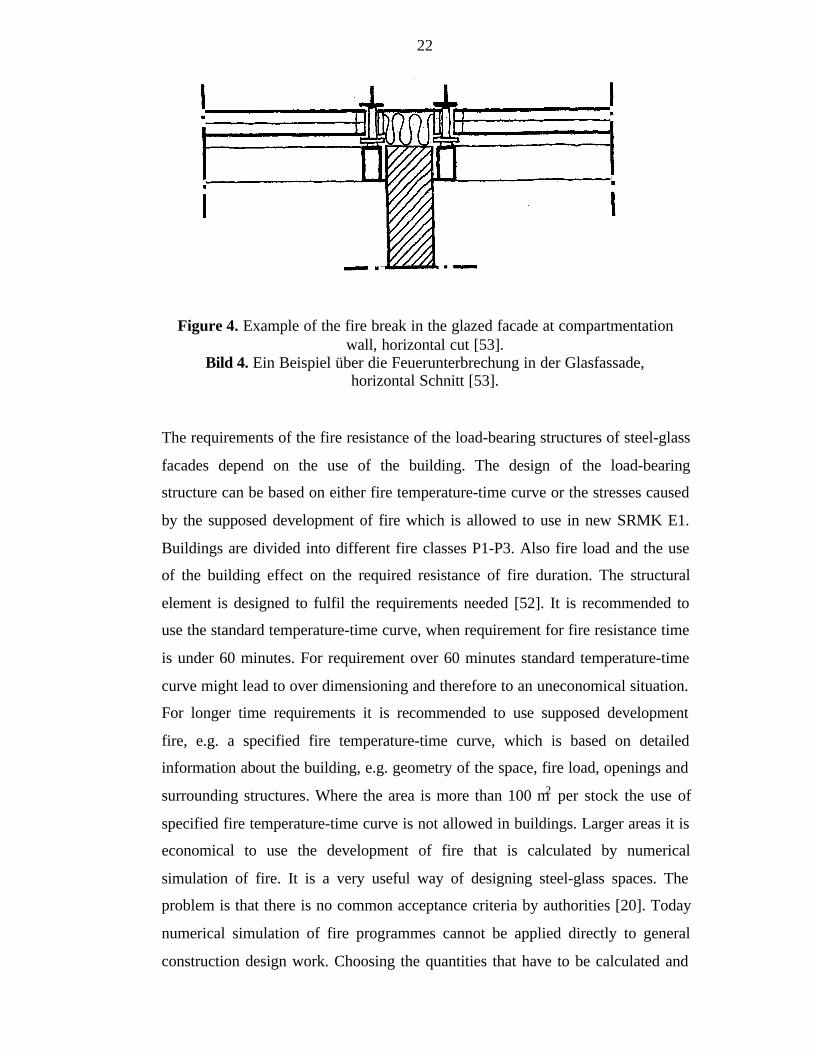
In glazed facades where there is a structural compartmentation element, a solid
break has to be constructed. The solid break should be made of incombustible
materials and its thickness should be the same as either the wall’s or the
intermediate floor’s thickness (see Figure 4). Double glazed facades, with a wide
air channel in between the outer and inner surfaces, have to be designed in
cooperation with local building inspection authorities and fire authorities [53].
The danger of fire spreading from the compartment to another has to be taken care
of.
22
The requirements of the fire resistance of the load-bearing structures of steel-glass
facades depend on the use of the building. The design of the load-bearing
structure can be based on either fire temperature-time curve or the stresses caused
by the supposed development of fire which is allowed to use in new SRMK E1.
Buildings are divided into different fire classes P1-P3. Also fire load and the use
of the building effect on the required resistance of fire duration. The structural
element is designed to fulfil the requirements needed [52]. It is recommended to
use the standard temperature-time curve, when requirement for fire resistance time
is under 60 minutes. For requirement over 60 minutes standard temperature-time
curve might lead to over dimensioning and therefore to an uneconomical situation.
For longer time requirements it is recommended to use supposed development
fire, e.g. a specified fire temperature-time curve, which is based on detailed
information about the building, e.g. geometry of the space, fire load, openings and
surrounding structures. Where the area is more than 100 m2 per stock the use of
specified fire temperature-time curve is not allowed in buildings. Larger areas it is
economical to use the development of fire that is calculated by numerical
simulation of fire. It is a very useful way of designing steel-glass spaces. The
problem is that there is no common acceptance criteria by authorities [20]. Today
numerical simulation of fire programmes cannot be applied directly to general
construction design work. Choosing the quantities that have to be calculated and
Figure 4. Example of the fire break in the glazed facade at compartmentationwall, horizontal cut [53].
Bild 4. Ein Beispiel über die Feuerunterbrechung in der Glasfassade,horizontal Schnitt [53].
23
interpreting results require information about the models that are the background
of the software, about the basic principles of the fire calculation and about the fire
technique [54]. The user have to also have a critical attitude to the simulation
results and must have an idea of the order of “the right answer”.
For a normal commercial building, in which steel-glass facades are normally used,
the requirement for load-bearing structures is 120 minutes without collapsing and
for over 8-storey-buildings it is 180 minutes [52]. The structures are designed
according to SRMK B7 part 4 using material properties calculated in part 8 [55].
2.4.3.4 Association of Finnish Civil Engineers (RIL) [56]
Association of Finnish Civil Engineers (RIL) has published one book of design
guidelines named Transparent Structures. This publication introduces the main
aspects of functional tasks and requirements of designing transparent structures.
The book is applied for transparent roofs and walls of the shells of the building. It
can be applied also for the shells of buildings that are not transparent but made of
glass. The guidelines are not made for designing or carrying out the space with
transparent shell. This means there are no instructions for designing thermal,
humid or acoustic conditions in these design guidelines.
Requirements for transparent structures are gathered in these guidelines. The
requirements are;
- dimensions and tolerances,
- appearance,
- strength in serviceability and ultimate limit states,
- fire protection (in roofs)
- humidity technical function
- temperature technical function
- light technical function
- radiation technical function
- acoustical function
- strength against chemical and physical loads

24
- strength against biological loads
- time of duration and use
- installation
- serviceability
The requirements are gathered in this book from the matter depending parts of
SRMK.
Dimensions and tolerances
Tolerances of steel and steel sheet structures are given in SRMK B6 and B7 and
for aluminium in RIL guideline. Tolerances of insulated glass are given in Tables
3 and 4. The maximum size of insulation glass elements depends on transport,
installation place and installation equipment. When determining the size, also the
possible breaking and changing of the element during the period of use has to be
taken care of. If the elements are transferred by hand the maximum recommended
size of insulation glass element is 2000 mm x 2000 mm and the maximum
recommended weight is 80 kg. If it is possible to use lifting and transport
machines during the whole installation period, other dimensions can be used. Bent
glass sheets and insulation sheets have to be designed case by case.
25
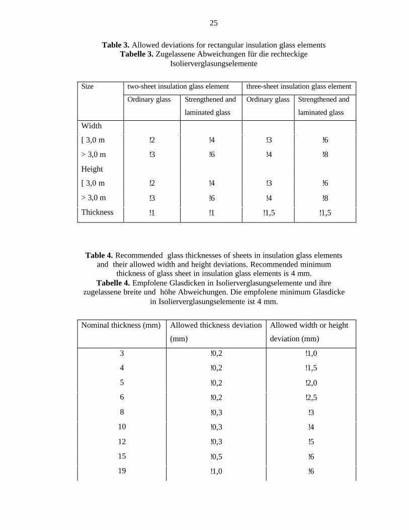
Table 3. Allowed deviations for rectangular insulation glass elementsTabelle 3. Zugelassene Abweichungen für die rechteckige
Isolierverglasungselemente
two-sheet insulation glass element three-sheet insulation glass elementSize
Ordinary glass Strengthened and
laminated glass
Ordinary glass Strengthened and
laminated glass
Width
[ 3,0 m !2 !4 !3 !6
> 3,0 m !3 !6 !4 !8
Height
[ 3,0 m !2 !4 !3 !6
> 3,0 m !3 !6 !4 !8
Thickness !1 !1 !1,5 !1,5
Table 4. Recommended glass thicknesses of sheets in insulation glass elementsand their allowed width and height deviations. Recommended minimum
thickness of glass sheet in insulation glass elements is 4 mm.Tabelle 4. Empfolene Glasdicken in Isolierverglasungselemente und ihre
zugelassene breite und höhe Abweichungen. Die empfolene minimum Glasdickein Isolierverglasungselemente ist 4 mm.
Nominal thickness (mm) Allowed thickness deviation
(mm)
Allowed width or height
deviation (mm)
3 !0,2 !1,0
4 !0,2 !1,5
5 !0,2 !2,0
6 !0,2 !2,5
8 !0,3 !3
10 !0,3 !4
12 !0,3 !5
15 !0,5 !6
19 !1,0 !6
26
25 !1,0 !8
Strength in serviceability and ultimate limit states
Loads for load-bearing structures are given in SRMK B1 and in guideline RIL
144. The regulations and guidelines are same for all load-bearing structures, but,
when concerning static loads, with glazed structures special attention should be
given to temperature loads because of their uniqueness. Temperature distribution
of transparent structures in thickness direction has to be known, when estimating
the deflections and stresses caused by temperature differences in structure.
Especially temperature distribution is needed for estimating displacements and
stresses of seals and joints. In designing the glass sheet also uneven temperature
distribution caused by sharp edges of shadows has to be taken care of. The loads
of the gas expansion between the sheets in two and three layered glass elements
have to be taken care of as well.
In Finland the outside temperatures used in designing transparent structures vary
between –30 ºC and +70 ºC. Temperature of structures inside buildings is
determined by the inside temperature.
Impact loads of glazed structures are important. The impacts tests and
requirements of different kind of glass classes are given in SFS standards 5310,
5311, 5312 and 5314.
Horizontal loads, like wind loads, temperature differences, explosions and
earthquakes, cause displacements that bring loads to transparent structures. The
loads are to be taken care of especially when using structural silicone glazing.
Quality control in structural glazing has to be done by regular quality control tests
during manufacturing. Design and quality control tests are done according to the
guideline of Technical Agrément in Construction (UEAtc) [57] . Tests are carried
out with small specimen. Tests involve tensile and shear experiments in room
temperature and also in low (-20ºC) and high (+60ºC) temperatures. Before
strength tests specimens are aged in conditions matching the using period.
27
3 STEEL-GLASS FACADES
3.1 In General
Steel and glass are important materials in modern constructing. Their lightness,
clearness of structure and transparency are appearance properties that make them
wanted in new commercial and public buildings. In construction, as in other
disciplines, the fundamental need is to predict glass behaviour in facades with
more and more certainty to achieve better performance, and to do both more
economically.
The surface of a building has five fundamental roles [58];
- to keep the water and cold out
- to provide sufficient thermal insulation
- to shade interior from excessive solar gain
- to provide views out for occupants
- to let daylight into the space
With a correct design and planning the first three characteristics are possible to
gain, although they do not naturally suggest sheet glass to be an ideal material.
3.2 Supporting Steel Structures
3.2.1 Conventional Supporting Structures
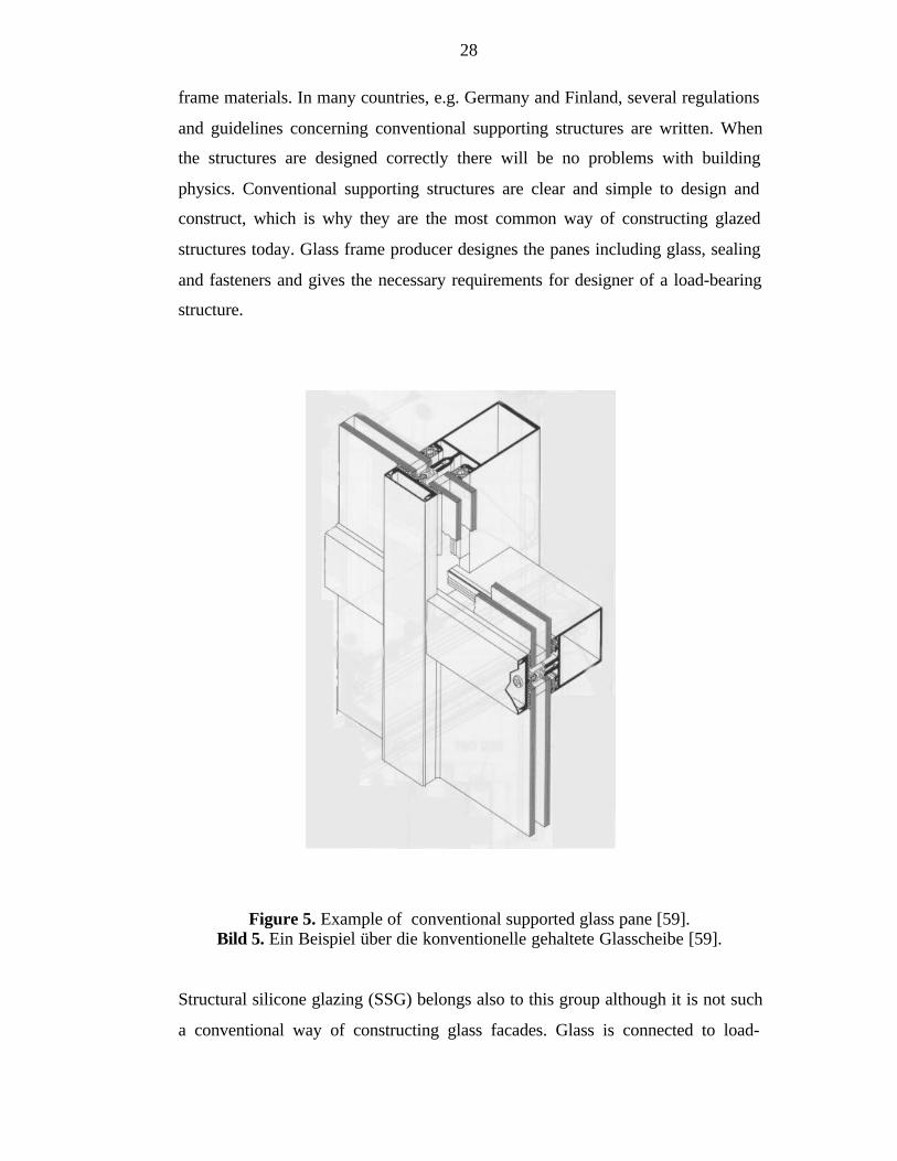
Conventional supporting structures (see Figure 5) mean glass facades where glass
is a secondary structure and every pane carries only its own wind load and its
dead load. The panes are supported by window frames, which are supported by a
load-bearing steel structure. Traditionally window frames are made of aluminium.
Wooden frames are used usually only in concrete and wooden frame buildings,
not in steel frame buildings. Plastic and stainless steel are used as new window
28
frame materials. In many countries, e.g. Germany and Finland, several regulations
and guidelines concerning conventional supporting structures are written. When
the structures are designed correctly there will be no problems with building
physics. Conventional supporting structures are clear and simple to design and
construct, which is why they are the most common way of constructing glazed
structures today. Glass frame producer designes the panes including glass, sealing
and fasteners and gives the necessary requirements for designer of a load-bearing
structure.
Figure 5. Example of conventional supported glass pane [59].Bild 5. Ein Beispiel über die konventionelle gehaltete Glasscheibe [59].
Structural silicone glazing (SSG) belongs also to this group although it is not such
a conventional way of constructing glass facades. Glass is connected to load-
29
bearing steel frame by silicone in SSG. Window frames are not used. SSG is
described in more detail in Chapter 4.2.3.
3.2.2 Hybrid-Supported Structures
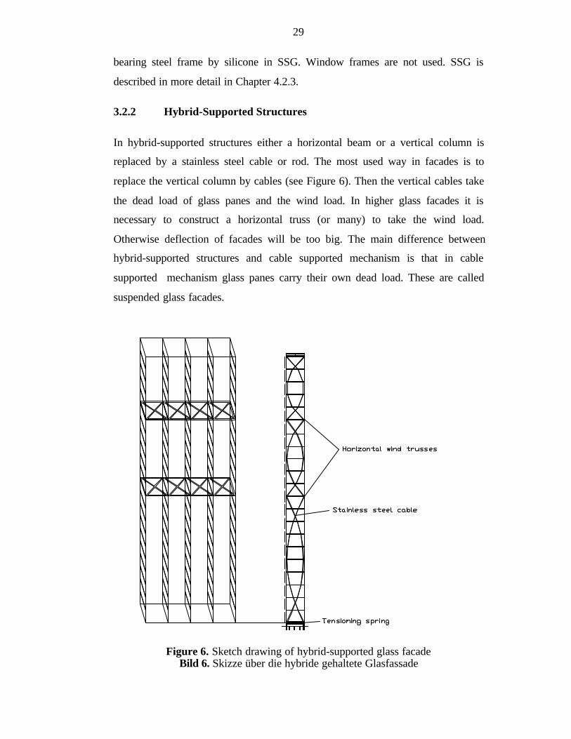
In hybrid-supported structures either a horizontal beam or a vertical column is
replaced by a stainless steel cable or rod. The most used way in facades is to
replace the vertical column by cables (see Figure 6). Then the vertical cables take
the dead load of glass panes and the wind load. In higher glass facades it is
necessary to construct a horizontal truss (or many) to take the wind load.
Otherwise deflection of facades will be too big. The main difference between
hybrid-supported structures and cable supported mechanism is that in cable
supported mechanism glass panes carry their own dead load. These are called
suspended glass facades.
Figure 6. Sketch drawing of hybrid-supported glass facadeBild 6. Skizze über die hybride gehaltete Glasfassade
30
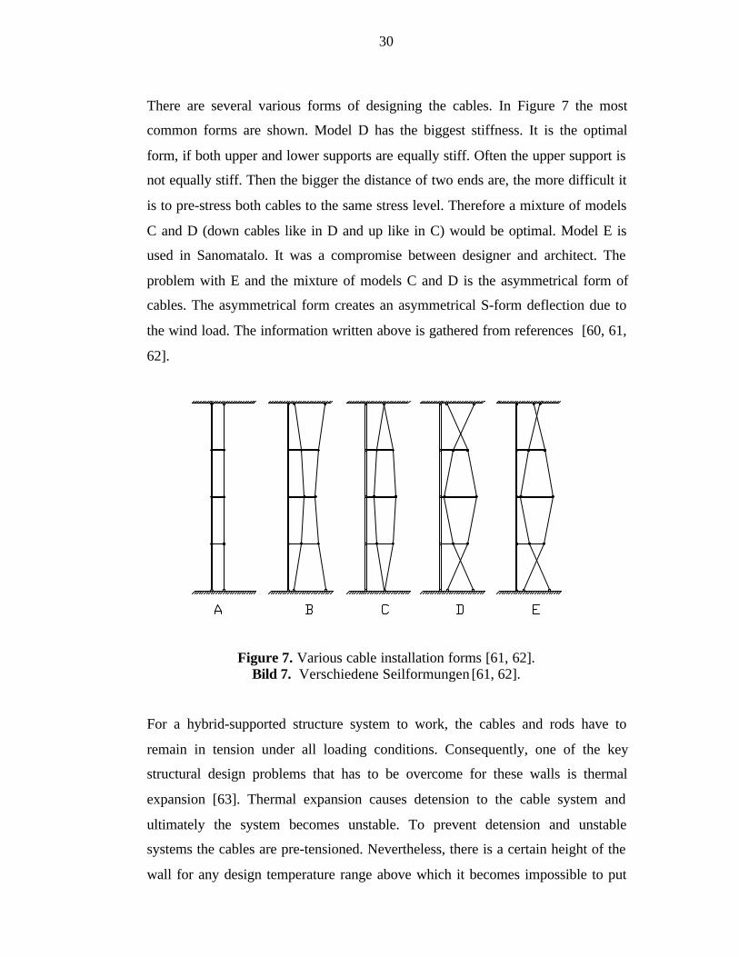
There are several various forms of designing the cables. In Figure 7 the most
common forms are shown. Model D has the biggest stiffness. It is the optimal
form, if both upper and lower supports are equally stiff. Often the upper support is
not equally stiff. Then the bigger the distance of two ends are, the more difficult it
is to pre-stress both cables to the same stress level. Therefore a mixture of models
C and D (down cables like in D and up like in C) would be optimal. Model E is
used in Sanomatalo. It was a compromise between designer and architect. The
problem with E and the mixture of models C and D is the asymmetrical form of
cables. The asymmetrical form creates an asymmetrical S-form deflection due to
the wind load. The information written above is gathered from references [60, 61,
62].
Figure 7. Various cable installation forms [61, 62].Bild 7. Verschiedene Seilformungen [61, 62].
For a hybrid-supported structure system to work, the cables and rods have to
remain in tension under all loading conditions. Consequently, one of the key
structural design problems that has to be overcome for these walls is thermal
expansion [63]. Thermal expansion causes detension to the cable system and
ultimately the system becomes unstable. To prevent detension and unstable
systems the cables are pre-tensioned. Nevertheless, there is a certain height of the
wall for any design temperature range above which it becomes impossible to put

31
sufficient initial pre-tension into the cables to overcome the effects of thermal
expansion. The solution used in higher walls is to use springs for each vertical
truss to pre-tension the cables and rods. The variation in the tension over design
temperature range is greatly reduced and all the elements of the structural system
always remain in tension. The height, when springs have to be used, depends on a
diameter and material of cable and the place of cables (in warm, in half warm or
outside) side of the buildings (south or north). E.g. in Sanomatalo in Helsinki the
facade is 30 metres high and cables are only pre-tensioned and in the Korean
World Trade Centre the same height of the facade was used springs.
To design this kind of higher walls with spring systems non-linear structural
analysis is needed to determine the forces, stability and the natural frequency
response [63]. Despite all modern design programs a certain amount of trial and
error is still required to balance the rod and catenary system with the floor spring.
An example of the floor spring is in Figure 8.
Figure 8. Example of floor spring joint (the Korean World Trade Centre) [63].Bild 8. Ein Beispiel über die Bodenfederknote (the Korean World Trade Centre)
[63].
32
When using slender structures, especially cables, deformation often becomes the
determining factor. How much deformation can be allowed then? Normally, a
threshold of permissible deformation is established for frequent wind loads that
are compatible with the glass or cladding systems involved. The joints in these
systems permits degrees of movement that are compatible with the threshold [17].
Above the threshold the cladding can be damaged. In pinned joints quite large
deformation thresholds can be permitted, because the system allows a
considerable degree of movement. However, there is a further limit to deflection.
Even if the cladding fixing system permits a considerable deflection, there is a
psychological limit that is the point at which the movement disturbs the general
public [17].
Installation of glass panes to a wide and high hybrid-supported glass facade might
be a difficult task. The easiest and cheapest way to install the panes is to use one
crane and start from the bottom of e.g. left column then install all the panes in that
column. Next move the crane to the second column and install from bottom to up
all glass panes and so on the whole facade. The problem is asymmetrical increase
of the loads to the cables. The rectangular pane places turn into diamond-shaped
very easily and then installation of the panes is not possible any more. The
solution is to start the installation from the bottom of all columns and install the
panes row by row. Then increase of the loads is symmetrical. But when installing
the panes like this one needs many cranes which is not economical. The solution
has to be found somewhere between these installation types. The information
above can be found in reference [60].
Often hybrid-supported structures are used in high buildings. The panes are
connected to each other by some kind of steel list. Then the structural difficulty is
in designing the structure, pretensioning the cables and installing the panes and
not in fastening details of the glass pane. Great buildings that are constructed with
hybrid supported structures are e.g. the Korean World Trade Centre [63],
Düsseldorfer Stadttor [64], Bauwenshaus in Leipzig, [64] and Sanomatalo in
Helsinki [61].
33
3.2.3 Supporting Cable Mechanism
3.2.3.1 In General
One special form of supporting structures is the supporting cable mechanism.
Conventional tubular frames are replaced by cables and rods in both vertical and
horizontal directions. Glazed structures, that consist of steel as a supporting cable
mechanism, are remarkable for their esthetics and their light weight structural
system. Especially the light weight concept, which is achieved by a minimum use
of material and often by the use of glass as a load carrying element, requires
careful design in accordance with the safety criteria used in structural engineering,
since there are no design standards for load carrying glass members.
There are various possibilities to carry the wind and dead load which are the main
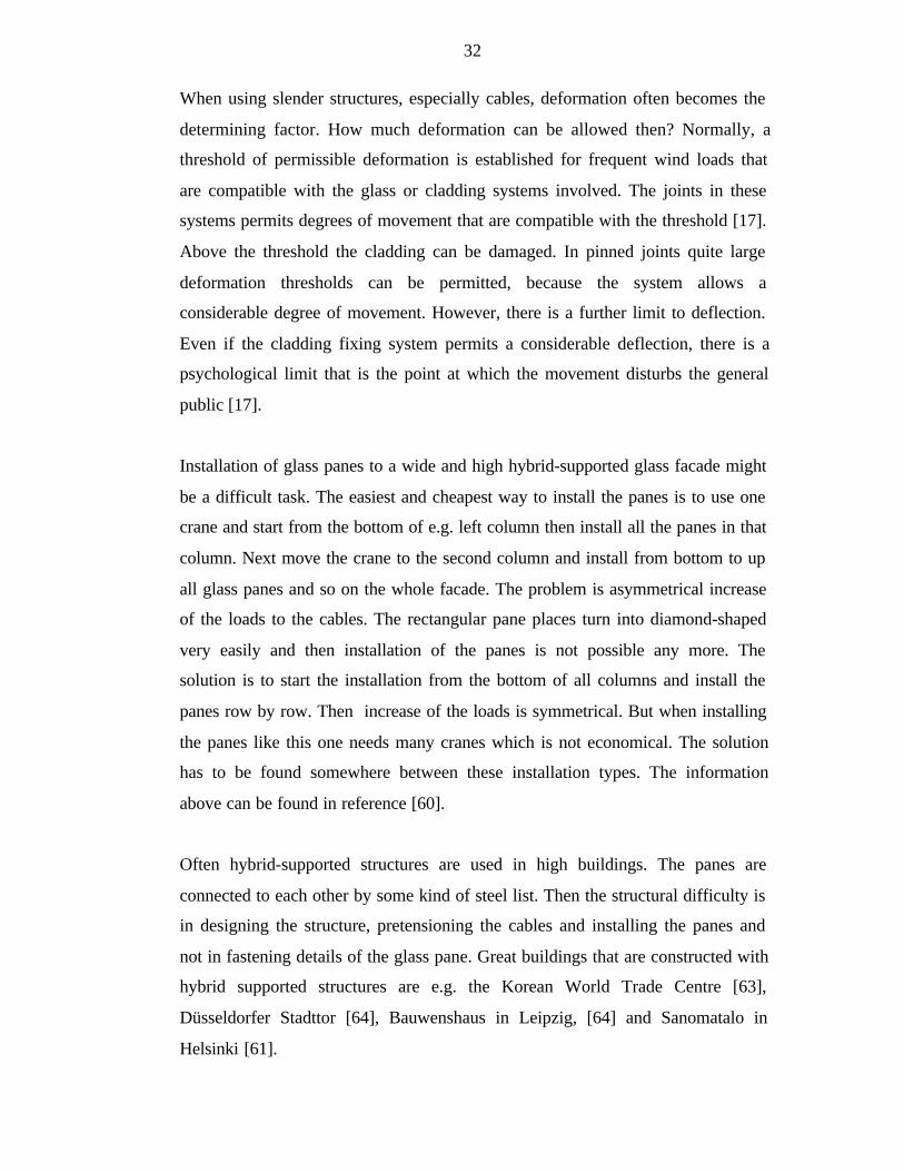
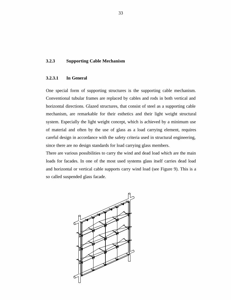
loads for facades. In one of the most used systems glass itself carries dead load
and horizontal or vertical cable supports carry wind load (see Figure 9). This is a
so called suspended glass facade.
34
Figure 9. Model of cable supported suspended glass facade [17].Bild 9. Modelle von den Seilverspannten Glasfassade [17].
3.2.3.2 Suspended Glass Facade [17]
As the underlying principle of the suspension system (see Figure 9) is the
predictability, that the suspension elements must be such that the designer will be
able to predict exactly how each panel will behave under various deflections and
movements.
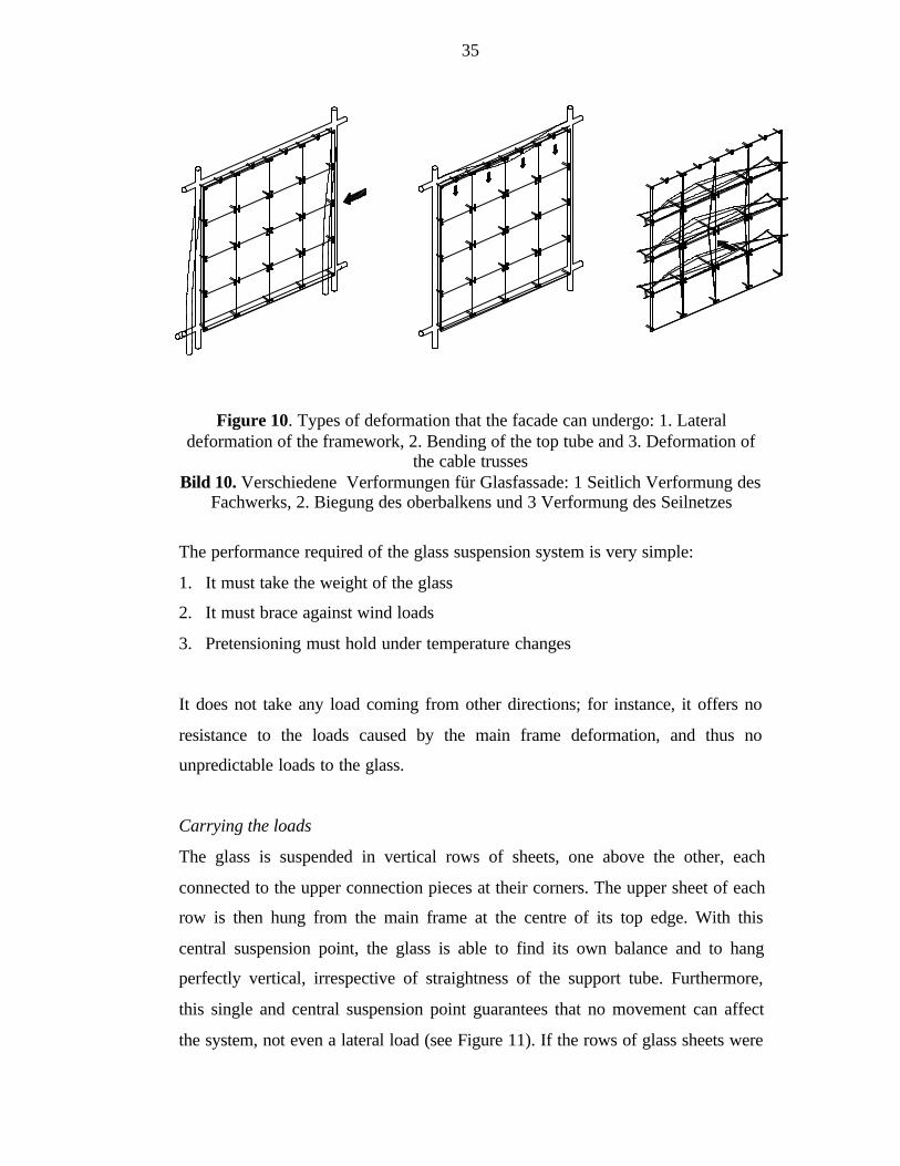
There are three types of deformation (see Figure 10) that need to be taken into
account. Firstly, the main frame can deform under strong wind if the truss has no
diagonal bracing members. If wind bracing is used, then this deformation is not to
be considered. Secondly, the top suspension tube can deflect under weight of
snow on the roof and under live loads on different levels. Thirdly, the deflections
of the cable truss, caused by wind, must be taken into account.
The first two deflections are particularly significant because they can cause
deformation of the plane of the suspended glass. Each sheet of glass remaining
rigid and perfectly square, any movement is thus concentrated at the support
points between two sheets and between the glass curtain and its supporting
structure. Deflections of the cable truss are concentrated around the holes drilled
in the glass.
35
Figure 10. Types of deformation that the facade can undergo: 1. Lateraldeformation of the framework, 2. Bending of the top tube and 3. Deformation of
the cable trussesBild 10. Verschiedene Verformungen für Glasfassade: 1 Seitlich Verformung des
Fachwerks, 2. Biegung des oberbalkens und 3 Verformung des Seilnetzes
The performance required of the glass suspension system is very simple:
1. It must take the weight of the glass
2. It must brace against wind loads
3. Pretensioning must hold under temperature changes
It does not take any load coming from other directions; for instance, it offers no
resistance to the loads caused by the main frame deformation, and thus no
unpredictable loads to the glass.
Carrying the loads
The glass is suspended in vertical rows of sheets, one above the other, each
connected to the upper connection pieces at their corners. The upper sheet of each
row is then hung from the main frame at the centre of its top edge. With this
central suspension point, the glass is able to find its own balance and to hang
perfectly vertical, irrespective of straightness of the support tube. Furthermore,
this single and central suspension point guarantees that no movement can affect
the system, not even a lateral load (see Figure 11). If the rows of glass sheets were
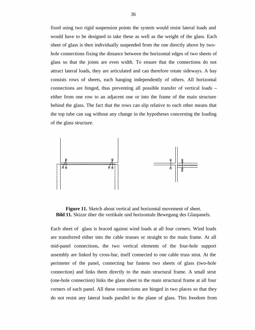
36
fixed using two rigid suspension points the system would resist lateral loads and
would have to be designed to take these as well as the weight of the glass. Each
sheet of glass is then individually suspended from the one directly above by two-
hole connections fixing the distance between the horizontal edges of two sheets of
glass so that the joints are even width. To ensure that the connections do not
attract lateral loads, they are articulated and can therefore rotate sideways. A bay
consists rows of sheets, each hanging independently of others. All horizontal
connections are hinged, thus preventing all possible transfer of vertical loads –
either from one row to an adjacent one or into the frame of the main structure
behind the glass. The fact that the rows can slip relative to each other means that
the top tube can sag without any change in the hypotheses concerning the loading
of the glass structure.
Figure 11. Sketch about vertical and horizontal movement of sheet.Bild 11. Skizze über die vertikale und horizontale Bewegung des Glaspanels.
Each sheet of glass is braced against wind loads at all four corners. Wind loads
are transferred either into the cable trusses or straight to the main frame. At all
mid-panel connections, the two vertical elements of the four-hole support
assembly are linked by cross-bar, itself connected to one cable truss strut. At the
perimeter of the panel, connecting bar fastens two sheets of glass (two-hole
connection) and links them directly to the main structural frame. A small strut
(one-hole connection) links the glass sheet to the main structural frame at all four
corners of each panel. All these connections are hinged in two places so that they
do not resist any lateral loads parallel to the plane of glass. This freedom from
37
lateral restraint means that the plane is not affected by the tendency of the main
frame to adopt a parallelogram shape under lateral load conditions.
The only part of the suspension system offering a resistance to lateral loads in the
plane of the glass is in middle of the top tube of a main structural frame bay. It is
hinged vertically and so does not alter the structural hypothesis when is deflection
in the main frame top tube; nor does is interfere with the freedom of the panels
with regard to the main frame parallelogram action, since it is located on the top
tube itself. Temperature fluctuations cause the frame and the glass to expand and
contract at different rates. The fact that there is only on a fixed point between
these two systems in the plane of the glass and that all other connection points are
free to rotate allows for differential thermal expansion.
Although each of the rows of a panel are theoretically free to slip relative to each
other, the resistance provided by the silicone weatherproofing of the joints must
be taken into account. In fact entire facade has a tendency to behave as one single
sheet. Lateral loads in the plane of the glass would create support moments and
might cause significant changes in the loads at each support point. This is why a
pretensioned spring mechanism is incorporated into each support bracket in such
a manner as to ensure that the weight of the whole panel is always evenly
distributed between all support points. Each mechanism remains rigid until it is
subjected to loads greater than the weight of the glass and fittings. Should any
more of the springs be subjected to a load of more than the weight of the glass, it
will sag until the remaining support take up the load. This “fuse” action is
necessary to enable prediction of the loads that can be applied to the glass and
each support point of the structure frame. The springs also act as shock absorbers
for the entire glass system in the event of a fracture in a sheet of glass and
consequent instant change in the load path.
The joint between the panes must satisfy three requirements; firstly, it must allow
the panels to move in relation to one another, secondly, it must not protrude from
the glass external skin, thirdly, it must be watertight.
38
The designer must provide capacity for adjustment to allow for manufacturing and
assembly tolerances of the system. It must be possible to adjust each element
according to the differences discovered, on site, between the theoretically
dimensions and the real dimensions of the structural frame and of the holes in the
glass sheets. Small inaccuracies can be found even in the most precise work, and
the accumulation of these inaccuracies can produce considerable dimensional
problems at the time of installation. Some inaccuracies are unavoidable, such as
the position of the holes in toughened glass. It has been seen that the glass
changes shape slightly in toughening oven as a result of the extreme heat. The
glass system consists of screw thread assemblies which enable the length of the
components to be changed in order to accommodate dimensional errors. These
assemblies must have been made so that they do not become accidentally
unscrewed. Assemblies can become adjustable simply because they are hinged.
For instance, the spring support assembly has a double hinge which makes lateral
adjustment possible. If a rigid bracket were used instead, and should it be
inaccurately welded to the main structure, it would be impossible to correct this
defect when fitting the glass sheet.
This type of facades are used in e.g. Cité des Sciences et de l’industrie –Parc de la
Villette in Paris, Channel 4 in London, Parc André Citroen in Paris, 50 Avenue
Montaigne in Paris [64]. No information of buildings with this type of load-
bearing structure constructed in Finland was found.
3.2.4 Double Face Facades
There are two separate glass surfaces in double face facades. The surfaces are
normally within 0,5-1 metres distance each other. Double face facades can be
constructed using a conventional supporting structure, a hybrid-supported
structure or a supporting cable mechanism, but because of their uniqueness they
have been written in their own paragraph.
39
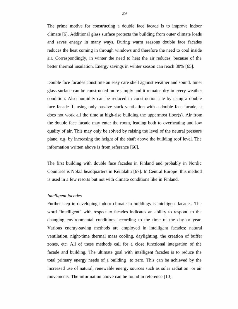
The prime motive for constructing a double face facade is to improve indoor
climate [6]. Additional glass surface protects the building from outer climate loads
and saves energy in many ways. During warm seasons double face facades
reduces the heat coming in through windows and therefore the need to cool inside
air. Correspondingly, in winter the need to heat the air reduces, because of the
better thermal insulation. Energy savings in winter season can reach 30% [65].
Double face facades constitute an easy care shell against weather and sound. Inner
glass surface can be constructed more simply and it remains dry in every weather
condition. Also humidity can be reduced in construction site by using a double
face facade. If using only passive stack ventilation with a double face facade, it
does not work all the time at high-rise building the uppermost floor(s). Air from
the double face facade may enter the room, leading both to overheating and low
quality of air. This may only be solved by raising the level of the neutral pressure
plane, e.g. by increasing the height of the shaft above the building roof level. The
information written above is from reference [66].
The first building with double face facades in Finland and probably in Nordic
Countries is Nokia headquarters in Keilalahti [67]. In Central Europe this method
is used in a few resorts but not with climate conditions like in Finland.
Intelligent facades
Further step in developing indoor climate in buildings is intelligent facades. The
word “intelligent” with respect to facades indicates an ability to respond to the
changing environmental conditions according to the time of the day or year.
Various energy-saving methods are employed in intelligent facades; natural
ventilation, night-time thermal mass cooling, daylighting, the creation of buffer
zones, etc. All of these methods call for a close functional integration of the
facade and building. The ultimate goal with intelligent facades is to reduce the
total primary energy needs of a building to zero. This can be achieved by the
increased use of natural, renewable energy sources such as solar radiation or air
movements. The information above can be found in reference [10].
40
3.3 Fire Safety of Steel-Glass Structures
Although steel and glass both are incombustible materials, there are partly real
and partly imagined problems in fire protection of steel-glass facades. Fire safety
is an important and sometimes a difficult matter to concern in steel-glass facades
[68]. The main element of the constructional fire prevention concept is the
establishment of fire and smoke compartments in buildings. These may be
achieved by the use of fire-resisting glass systems and smoke-resisting glass
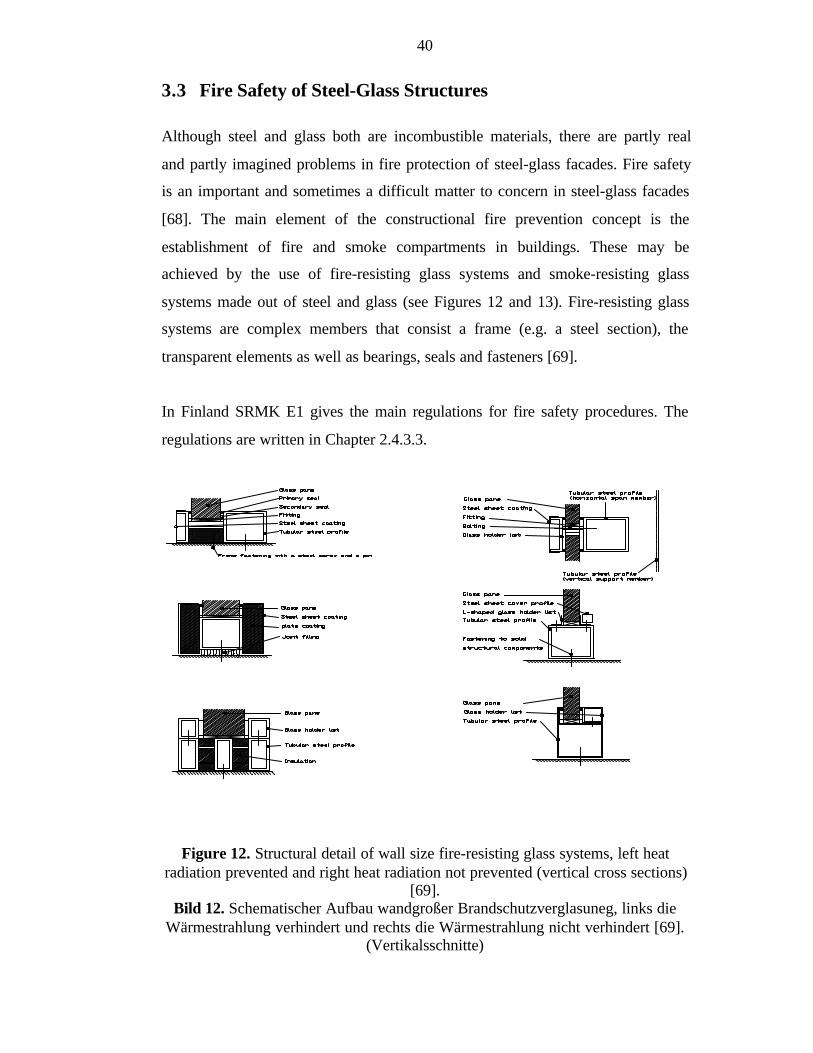
systems made out of steel and glass (see Figures 12 and 13). Fire-resisting glass
systems are complex members that consist a frame (e.g. a steel section), the
transparent elements as well as bearings, seals and fasteners [69].
In Finland SRMK E1 gives the main regulations for fire safety procedures. The
regulations are written in Chapter 2.4.3.3.
Figure 12. Structural detail of wall size fire-resisting glass systems, left heatradiation prevented and right heat radiation not prevented (vertical cross sections)
[69].Bild 12. Schematischer Aufbau wandgroßer Brandschutzverglasuneg, links die
Wärmestrahlung verhindert und rechts die Wärmestrahlung nicht verhindert [69].(Vertikalsschnitte)

41
Figure 13. Structural detail of wall size fire resisting glass element, heat radiationnot prevented (vertical cross section) [69].
Bild 13. Schematischer Aufbau von Branschutzverglasungselement, dieWärmestrahlung nicht verhindert (Vertikalschnitt) [69].
Fire technical type approval of structural elements in Finland
Fire technical type approval can be applied from the Finnish Ministry of the
Environment for structural elements. To get the approval, fire resistance has to be
determined with test methods that are approved in the Ministry. The Ministry of
the Environment confirms type approval of a product when quality control
agreement for the product that has acceptably passed a type approval test has been
made with the research laboratory. For glazed structures the maximum size of the
panes and the height of the wall structure is often limited in conditions of the type
approval. There might also be other limitations in the conditions. The information
written above is from reference [70].
Type approval is a national acceptance system. Therefore getting a type approval
licence does not entitle to use the CE-symbol.
Wired glass is often used in compartment walls because it retains the tightness,
which is important to prohibit the spread of fire. But wired glass is quite brittle
and it tends to crack due to stresses caused by temperature. Therefore it is not
recommended to be used in facades, because the stress at the boundary of sun
shine and shadow can break the glass [53]. Also, architects do not like the wires in
the glass.
42
4 FASTENINGS AND JOINTS IN STEEL-GLASS
FACADES
4.1 In General
The joints of steel and glass have the same requirements as does the whole
construction. Therefore joint details have to be designed to function as a part of
the whole facade. The following aspects are to be considered:
- Requirements of function and applicability in general have to be same as
other structures
- Loads caused by climate and mechanical movements
- Thermal insulation
- Sound insulation
- Requirement of compartmentation
- Protection against burglary
- Selecting materials
- Appearance
- Expediency in designing and structure
- Feasibility
- Need of service, serviceable and reparable
Getting detailed information concerning the joints is sometimes difficult.
Research and development of new joint types are often made or financed by a
company. The results are used for new products that are an important part of the
company’s competitive ability. Therefore only the products are shown, but not the
research and development data.
43
4.2 Mechanical Fastening
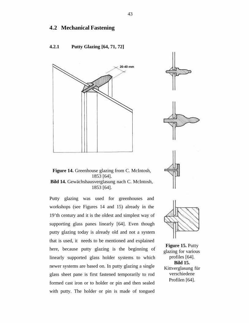
4.2.1 Putty Glazing [64, 71, 72]
Figure 14. Greenhouse glazing from C. McIntosh,1853 [64].
Bild 14. Gewächshausverglasung nach C. McIntosh,1853 [64].
Putty glazing was used for greenhouses and
workshops (see Figures 14 and 15) already in the
19’th century and it is the oldest and simplest way of
supporting glass panes linearly [64]. Even though
putty glazing today is already old and not a system
that is used, it needs to be mentioned and explained
here, because putty glazing is the beginning of
linearly supported glass holder systems to which
newer systems are based on. In putty glazing a single
glass sheet pane is first fastened temporarily to rod
formed cast iron or to holder or pin and then sealed
with putty. The holder or pin is made of tongued
Figure 15. Puttyglazing for various
profiles [64].Bild 15.
Kittverglasung fürverschiedeneProfilen [64].
44
wood, metallic rolled or cast profiles. Also holders of plastic and composite
materials are possible materials of the holder or pin. After sealing, glass in
composite with tenacious elastic putty bed helps to stiffen the greenhouse
construction. Stiffening is more or less empirical-intuitive and cannot be taken
into account in design. Putty has double function here; it transfers the forces and it
seals the pane watertight. An essential basic rule for glazing is the necessity of
simply supported glass edges. Then there will be no uncontrolled compression
stresses from load-bearing structures. Rigid support would lead unavoidably to
breaking of the glass pane. Therefore elasticity is an essential property of putty.
Unfortunately putty has the disadvantage of becoming brittle being exposed to
UV radiation for long periods of time and looses its elasticity. The brittle putty
causes stresses to glass pane and that leads to the danger of glass breaking.
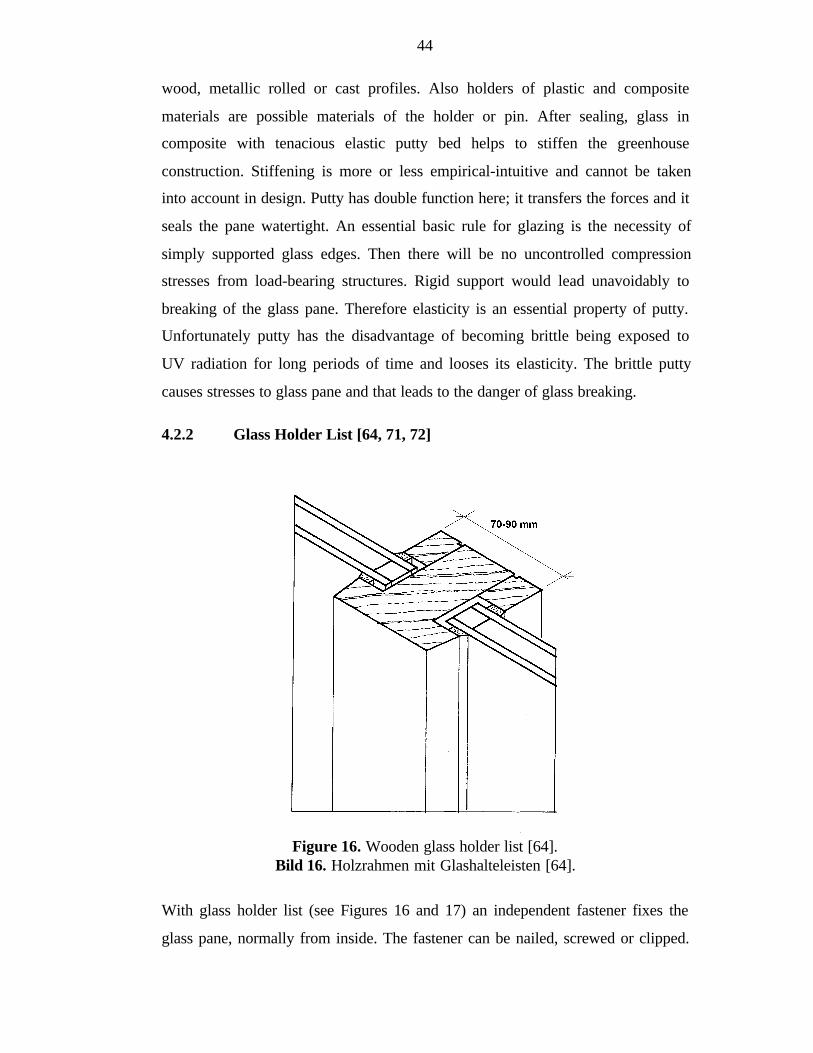
4.2.2 Glass Holder List [64, 71, 72]
Figure 16. Wooden glass holder list [64].Bild 16. Holzrahmen mit Glashalteleisten [64].
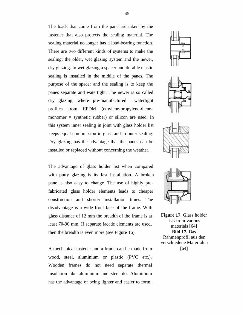
With glass holder list (see Figures 16 and 17) an independent fastener fixes the
glass pane, normally from inside. The fastener can be nailed, screwed or clipped.
45
The loads that come from the pane are taken by the
fastener that also protects the sealing material. The
sealing material no longer has a load-bearing function.
There are two different kinds of systems to make the
sealing; the older, wet glazing system and the newer,
dry glazing. In wet glazing a spacer and durable elastic
sealing is installed in the middle of the panes. The
purpose of the spacer and the sealing is to keep the
panes separate and watertight. The newer is so called
dry glazing, where pre-manufactured watertight
profiles from EPDM (ethylene-propylene-diene-
monomer = synthetic rubber) or silicon are used. In
this system inner sealing in joint with glass holder list
keeps equal compression in glass and in outer sealing.
Dry glazing has the advantage that the panes can be
installed or replaced without concerning the weather.
The advantage of glass holder list when compared
with putty glazing is its fast installation. A broken
pane is also easy to change. The use of highly pre-
fabricated glass holder elements leads to cheaper
construction and shorter installation times. The
disadvantage is a wide front face of the frame. With
glass distance of 12 mm the breadth of the frame is at
least 70-90 mm. If separate facade elements are used,
then the breadth is even more (see Figure 16).
A mechanical fastener and a frame can be made from
wood, steel, aluminium or plastic (PVC etc.).
Wooden frames do not need separate thermal
insulation like aluminium and steel do. Aluminium
has the advantage of being lighter and easier to form,
Figure 17. Glass holderlists from various
materials [64]Bild 17. Das
Rahmenprofil aus denverschiedene Materialen
[64]
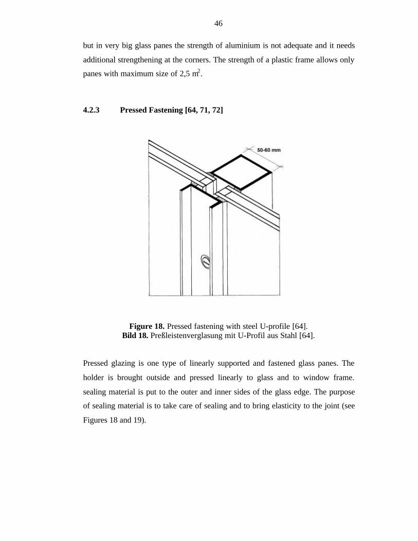
46
but in very big glass panes the strength of aluminium is not adequate and it needs
additional strengthening at the corners. The strength of a plastic frame allows only
panes with maximum size of 2,5 m2.
4.2.3 Pressed Fastening [64, 71, 72]
Figure 18. Pressed fastening with steel U-profile [64].Bild 18. Preßleistenverglasung mit U-Profil aus Stahl [64].
Pressed glazing is one type of linearly supported and fastened glass panes. The
holder is brought outside and pressed linearly to glass and to window frame.
sealing material is put to the outer and inner sides of the glass edge. The purpose
of sealing material is to take care of sealing and to bring elasticity to the joint (see
Figures 18 and 19).
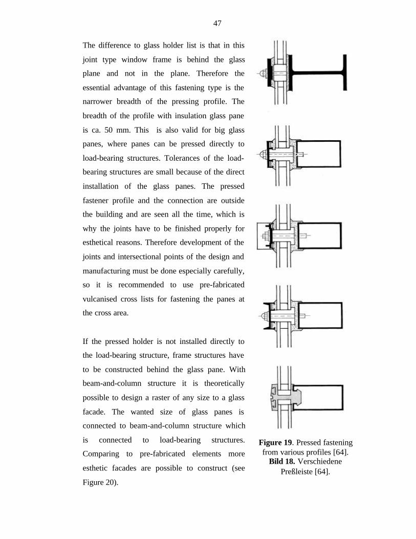
47
The difference to glass holder list is that in this
joint type window frame is behind the glass
plane and not in the plane. Therefore the
essential advantage of this fastening type is the
narrower breadth of the pressing profile. The
breadth of the profile with insulation glass pane
is ca. 50 mm. This is also valid for big glass
panes, where panes can be pressed directly to
load-bearing structures. Tolerances of the load-
bearing structures are small because of the direct
installation of the glass panes. The pressed
fastener profile and the connection are outside
the building and are seen all the time, which is
why the joints have to be finished properly for
esthetical reasons. Therefore development of the
joints and intersectional points of the design and
manufacturing must be done especially carefully,
so it is recommended to use pre-fabricated
vulcanised cross lists for fastening the panes at
the cross area.
If the pressed holder is not installed directly to
the load-bearing structure, frame structures have
to be constructed behind the glass pane. With
beam-and-column structure it is theoretically
possible to design a raster of any size to a glass
facade. The wanted size of glass panes is
connected to beam-and-column structure which
is connected to load-bearing structures.
Comparing to pre-fabricated elements more
esthetic facades are possible to construct (see
Figure 20).
Figure 19. Pressed fasteningfrom various profiles [64].
Bild 18. VerschiedenePreßleiste [64].
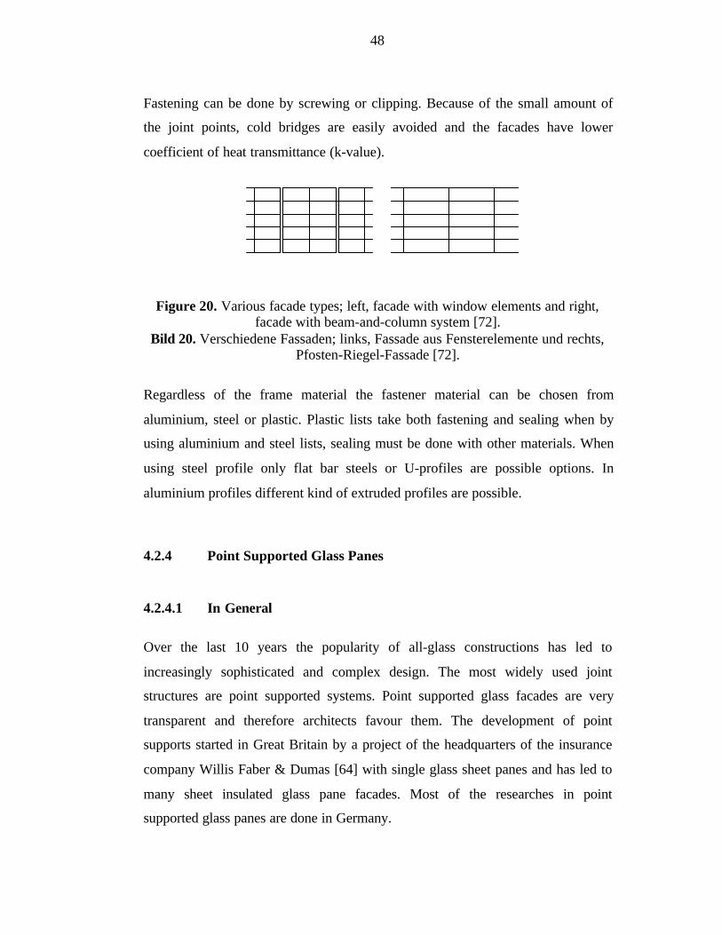
48
Fastening can be done by screwing or clipping. Because of the small amount of
the joint points, cold bridges are easily avoided and the facades have lower
coefficient of heat transmittance (k-value).
Figure 20. Various facade types; left, facade with window elements and right,facade with beam-and-column system [72].
Bild 20. Verschiedene Fassaden; links, Fassade aus Fensterelemente und rechts,Pfosten-Riegel-Fassade [72].
Regardless of the frame material the fastener material can be chosen from
aluminium, steel or plastic. Plastic lists take both fastening and sealing when by
using aluminium and steel lists, sealing must be done with other materials. When
using steel profile only flat bar steels or U-profiles are possible options. In
aluminium profiles different kind of extruded profiles are possible.
4.2.4 Point Supported Glass Panes
4.2.4.1 In General
Over the last 10 years the popularity of all-glass constructions has led to
increasingly sophisticated and complex design. The most widely used joint
structures are point supported systems. Point supported glass facades are very
transparent and therefore architects favour them. The development of point
supports started in Great Britain by a project of the headquarters of the insurance
company Willis Faber & Dumas [64] with single glass sheet panes and has led to
many sheet insulated glass pane facades. Most of the researches in point
supported glass panes are done in Germany.
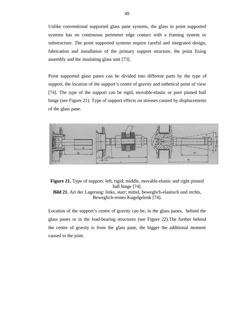
49
Unlike conventional supported glass pane systems, the glass in point supported
systems has no continuous perimeter edge contact with a framing system or
substructure. The point supported systems require careful and integrated design,
fabrication and installation of the primary support structure, the point fixing
assembly and the insulating glass unit [73].
Point supported glass panes can be divided into different parts by the type of
support, the location of the support’s centre of gravity and esthetical point of view
[74]. The type of the support can be rigid, movable-elastic or pure pinned ball
hinge (see Figure 21). Type of support effects on stresses caused by displacements
of the glass pane.
Figure 21. Type of support: left, rigid; middle, movable-elastic and right pinnedball hinge [74].
Bild 21. Art der Lagerung: links, starr; mittel, beweglich-elastisch und rechts,Beweglich-reines Kugelgelenk [74].
Location of the support’s centre of gravity can be; in the glass panes, behind the
glass panes or in the load-bearing structures (see Figure 22).The further behind
the centre of gravity is from the glass pane, the bigger the additional moment
caused to the joint.

50
Figure 22. Location of the centre of the gravity: left, in the glass panes; middle,behind the glass panes or right, in the load-bearing structures [74].
Bild 22. Ort der lagerungsausbildung: links, in der Glasebene; mittel, hinter derGlasebene oder rechts, an der Unterkonstruktion [74].
In architects’ point of view the point supports can be divided into three various
esthetic parts. The head of the bolt can be above the glass pane which is the
easiest and oldest way of constructing point supports. A more delicate way is to
level the bolt head to the glass pane plane. Then the point support cannot be seen
from the side of the glass pane. The newest way is to leave the bolt head inside the
glass pane. Then the head is “invisible” (see Figure 23).
Figure 23. Esthetical view points; a) joint is above glass pane, b) bolt head is onthe glass pane and c) bolt head is in the glass pane [74].
Bild 23. Ästhetische Gesichtspunkte; a) Rosetten sichtbar, b) Senkkopf sichtbarund c) Ohne sichtbaren Schraubenkopf [74].
4.2.4.2 Loads
In this delicate system the possible loads are to be calculated carefully. Too big
loads in the point support lead to cracks in the glass and then to a possible fall of
the pane. The main problems to overcome with point supported glass panes are:
51
1. high stresses at the edges of the drilling holes
2. small tolerances in the joint
3. restraint loads caused by temperature
4. additional loads to insulation glass panes
High stresses [75]
Because of clear, determined stress distribution, line supported glass panes in
facades can be designed easily with e.g. values in tables. Glass panes with point
support on contrary need more careful design calculations.
The condition of edges and glass surface in the drilling area has an essential effect
on load capacity. When designing the joint detail, the joint has to be modelled
with a FE-program. Because of the importance of the edge, the main concern has
to be in modelling the liner material between glass and fastener. Simplified FE-
model without liner modelling in drilling area is not adequate. Decisive in point
supported glass panes are normally principal tension stresses.
From experience of Wörner et al. [75] the following matters have very much
effect on the stresses at the edges of a drilling hole:
1. Type of the joint. The stresses are higher with fixed joints with eccentricity
than with pinned ball joints.
2. The drilling of the glass. It depends on diameter, condition of the glass, type
of the hole e.g. cone-shaped
3. Geometry
4. The liner material. It depends on thickness and stiffness of liner.
Small tolerances
When designing glazed structures required tolerances might be essentially smaller
than in normal construction. The more transparent the structure is the smaller the
tolerances are. The needed tolerances depend on the point support system. If the
joint can move in many directions, then the required tolerances of load-bearing
52
structures are not so small. Otherwise load-bearing structures have to be
constructed with tolerances that are unusually small to many constructors.
Restraint loads [72]
Restraint loads can easily break glass products where stress peaks cannot be
removed. There the panes have to be fastened so that stresses caused by restraint
loads are the lowest possible. This relates especially to the restraint caused by
temperature. Therefore various coefficients of thermal expansion of inner
structures and glass have to be considered of.
Glass can be e.g. pinned fastened with a ball joint (see Figure 24). When this is
the case the system is statically determined and restraint loads are avoided. Glass
as a material has no ability to form local plastic deformations like e.g. steel has.
Therefore the contact of the glass to other materials with equal or bigger modulus
of elasticity should be avoided. Instead plastic materials or aluminium are
recommended to use as liner e.g. in drilling and supporting areas. Durability of the
liner against UV light, water, etc. and its permanence has to be considered.
It is better to ensure fitting possibilities for geometrical inaccuracies already in the
design phase. E.g. repairing the drilling area afterwards in heat strengthened
laminated glass is not possible in situ.
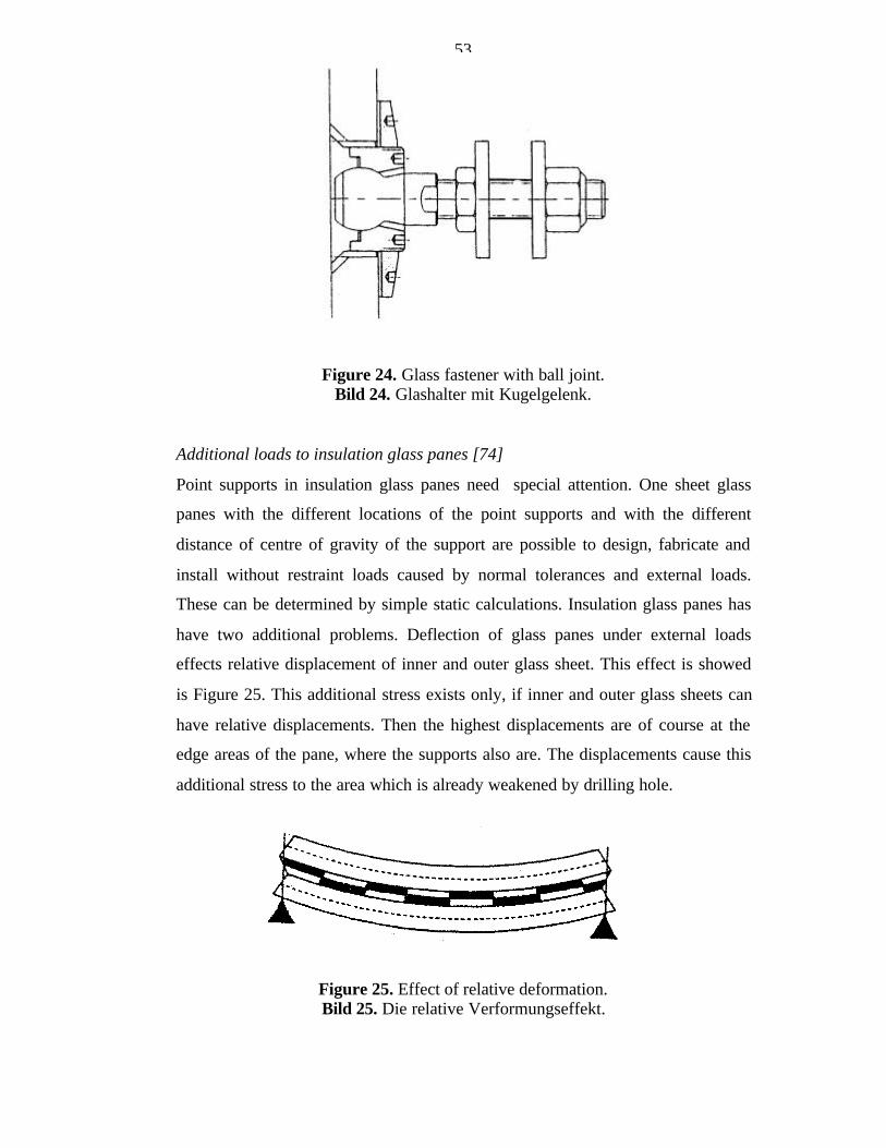
53
Figure 24. Glass fastener with ball joint.Bild 24. Glashalter mit Kugelgelenk.
Additional loads to insulation glass panes [74]
Point supports in insulation glass panes need special attention. One sheet glass
panes with the different locations of the point supports and with the different
distance of centre of gravity of the support are possible to design, fabricate and
install without restraint loads caused by normal tolerances and external loads.
These can be determined by simple static calculations. Insulation glass panes has
have two additional problems. Deflection of glass panes under external loads
effects relative displacement of inner and outer glass sheet. This effect is showed
is Figure 25. This additional stress exists only, if inner and outer glass sheets can
have relative displacements. Then the highest displacements are of course at the
edge areas of the pane, where the supports also are. The displacements cause this
additional stress to the area which is already weakened by drilling hole.
Figure 25. Effect of relative deformation.Bild 25. Die relative Verformungseffekt.
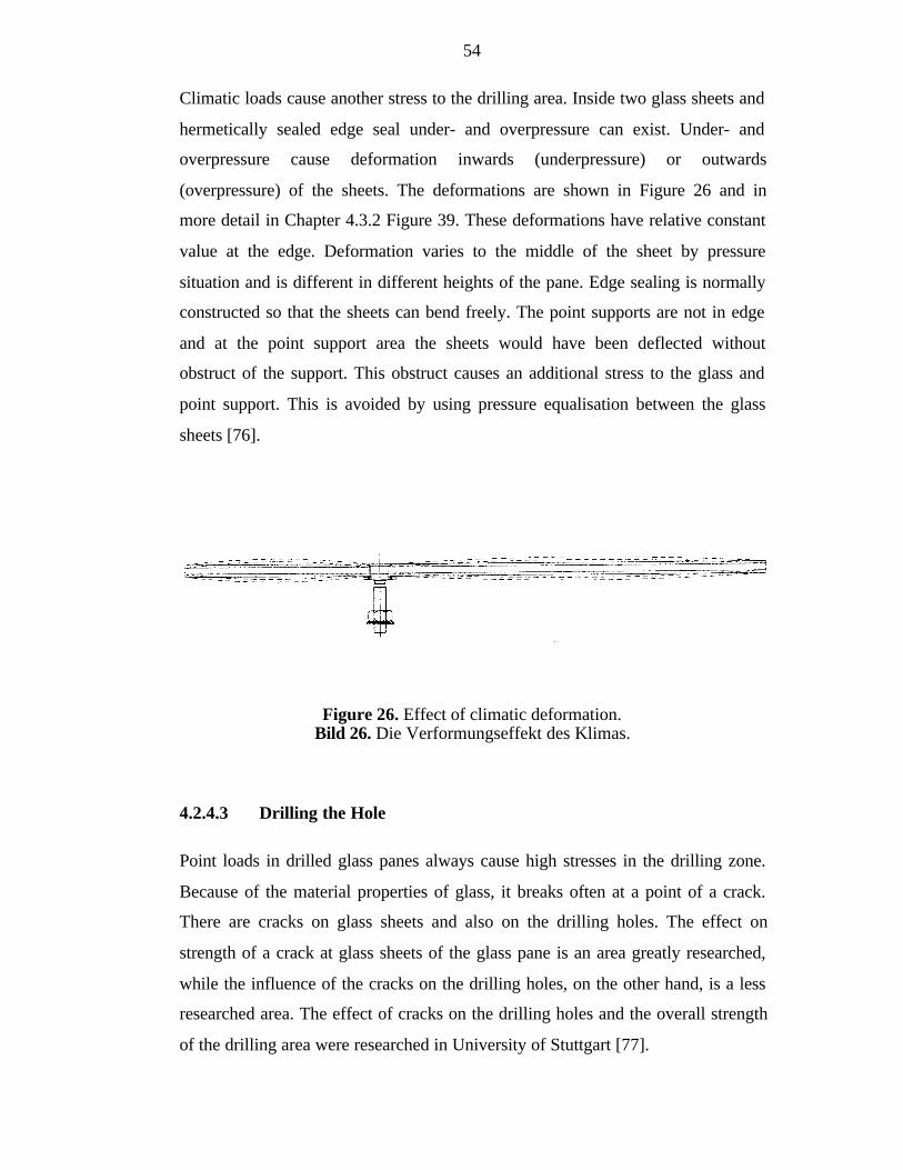
54
Climatic loads cause another stress to the drilling area. Inside two glass sheets and
hermetically sealed edge seal under- and overpressure can exist. Under- and
overpressure cause deformation inwards (underpressure) or outwards
(overpressure) of the sheets. The deformations are shown in Figure 26 and in
more detail in Chapter 4.3.2 Figure 39. These deformations have relative constant
value at the edge. Deformation varies to the middle of the sheet by pressure
situation and is different in different heights of the pane. Edge sealing is normally
constructed so that the sheets can bend freely. The point supports are not in edge
and at the point support area the sheets would have been deflected without
obstruct of the support. This obstruct causes an additional stress to the glass and
point support. This is avoided by using pressure equalisation between the glass
sheets [76].
Figure 26. Effect of climatic deformation.Bild 26. Die Verformungseffekt des Klimas.
4.2.4.3 Drilling the Hole
Point loads in drilled glass panes always cause high stresses in the drilling zone.
Because of the material properties of glass, it breaks often at a point of a crack.
There are cracks on glass sheets and also on the drilling holes. The effect on
strength of a crack at glass sheets of the glass pane is an area greatly researched,
while the influence of the cracks on the drilling holes, on the other hand, is a less
researched area. The effect of cracks on the drilling holes and the overall strength
of the drilling area were researched in University of Stuttgart [77].
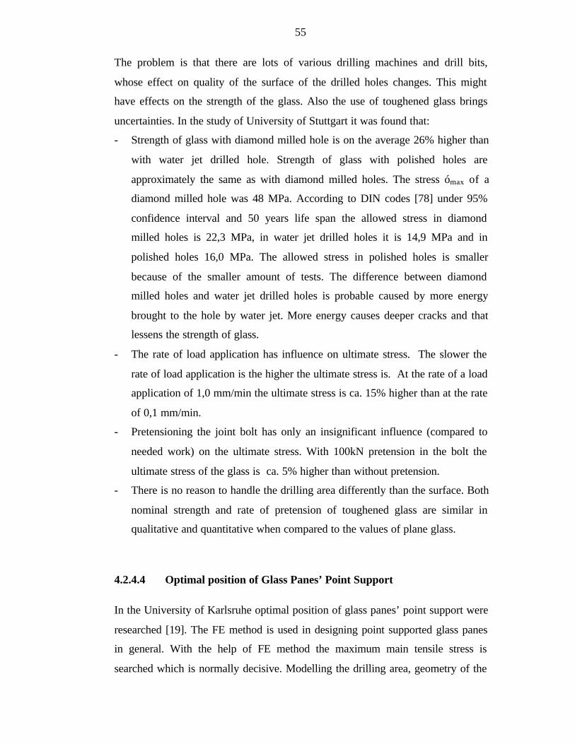
55
The problem is that there are lots of various drilling machines and drill bits,
whose effect on quality of the surface of the drilled holes changes. This might
have effects on the strength of the glass. Also the use of toughened glass brings
uncertainties. In the study of University of Stuttgart it was found that:
- Strength of glass with diamond milled hole is on the average 26% higher than
with water jet drilled hole. Strength of glass with polished holes are
approximately the same as with diamond milled holes. The stress ómax of a
diamond milled hole was 48 MPa. According to DIN codes [78] under 95%
confidence interval and 50 years life span the allowed stress in diamond
milled holes is 22,3 MPa, in water jet drilled holes it is 14,9 MPa and in
polished holes 16,0 MPa. The allowed stress in polished holes is smaller
because of the smaller amount of tests. The difference between diamond
milled holes and water jet drilled holes is probable caused by more energy
brought to the hole by water jet. More energy causes deeper cracks and that
lessens the strength of glass.
- The rate of load application has influence on ultimate stress. The slower the
rate of load application is the higher the ultimate stress is. At the rate of a load
application of 1,0 mm/min the ultimate stress is ca. 15% higher than at the rate
of 0,1 mm/min.
- Pretensioning the joint bolt has only an insignificant influence (compared to
needed work) on the ultimate stress. With 100kN pretension in the bolt the
ultimate stress of the glass is ca. 5% higher than without pretension.
- There is no reason to handle the drilling area differently than the surface. Both
nominal strength and rate of pretension of toughened glass are similar in
qualitative and quantitative when compared to the values of plane glass.
4.2.4.4 Optimal position of Glass Panes’ Point Support
In the University of Karlsruhe optimal position of glass panes’ point support were
researched [19]. The FE method is used in designing point supported glass panes
in general. With the help of FE method the maximum main tensile stress is
searched which is normally decisive. Modelling the drilling area, geometry of the

56
fastener, liner material between glass and steel is important to do carefully,
because of their major influence on the results. It is expensive to do such exact
calculations but cheaper and rough calculations are not reliable. Therefore
optimising the place of the point support is not economically profitable to do in
individual projects. In individual projects the architect normally decides the place
of the point support after which the needed glass thicknesses and joints are
calculated.
Point support fasteners that are available in market differ in static point of view in
two substantial areas:
- Distance from the middle of the glass pane to the centre of the rotation.
- Fasteners’ possibility to rotate changing from pinned to stiff.
An additional load to the glass pane is brought by moment caused by eccentric
place of the centre of rotation. The influence is especially extensive in restraint
caused by temperature expansion. Placing the centre of the rotation on the middle
of the glass pane this additional load is avoided.
In Table 5 the optimal positions for point supports are shown. The following
matters became clear in the research.
- When designing glass panes for dead load, edge distances have only minor
effect on main tension stresses.
- When designing glass panes against wind pressure the influence of the edge
distance is essential. For rectangular plate there is only a minor effect on main
tension stresses when changing br (see Figure 27), but optimising ar has
essential influence. For square plate optimising both ar and br have an essential
influence.
- When designing glass panes for temperature expansion or contraction, the
rigidity of the joint effects the most. With pinned or soft joint changing ar or br
has no effect on main tension stresses. With a rigid joint effect edge distances
are essential.
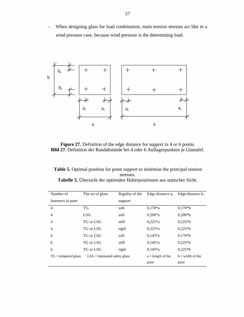
57
- When designing glass for load combination, main tension stresses act like in a
wind pressure case, because wind pressure is the determining load.
Figure 27. Definition of the edge distance for support in 4 or 6 points.Bild 27. Definition der Randabstände bei 4 oder 6 Auflagerpunkten je Glastafel.
Table 5. Optimal position for point support to minimise the principal tensionstresses.
Tabelle 5. Übersicht der optimalen Halterpositionen aus statischer Sicht.
Number of
fasteners in pane
The art of glass Rigidity of the
support
Edge distance ar Edge distance b r
4 TG soft 0,170*a 0,170*b
4 LSG soft 0,200*a 0,200*b
4 TG or LSG stiff 0,225*a 0,225*b
4 TG or LSG rigid 0,225*a 0,225*b
6 TG or LSG soft 0,145*a 0,170*b
6 TG or LSG stiff 0,145*a 0,225*b
6 TG or LSG rigid 0,145*a 0,225*b
TG = tempered glass LSG = laminated safety glass a = length of the
pane
b = width of the
pane
b
br
br
a
ar ar
a
ar ar
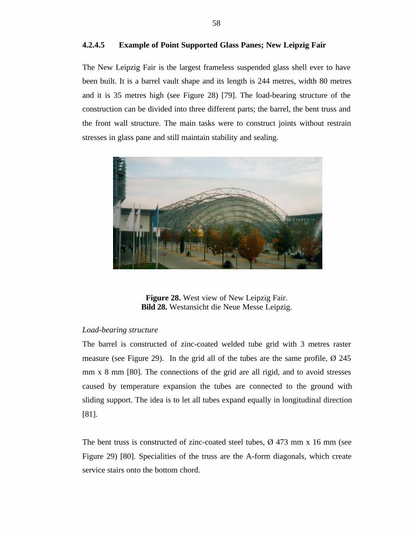
58
4.2.4.5 Example of Point Supported Glass Panes; New Leipzig Fair
The New Leipzig Fair is the largest frameless suspended glass shell ever to have
been built. It is a barrel vault shape and its length is 244 metres, width 80 metres
and it is 35 metres high (see Figure 28) [79]. The load-bearing structure of the
construction can be divided into three different parts; the barrel, the bent truss and
the front wall structure. The main tasks were to construct joints without restrain
stresses in glass pane and still maintain stability and sealing.
Figure 28. West view of New Leipzig Fair.Bild 28. Westansicht die Neue Messe Leipzig.
Load-bearing structure
The barrel is constructed of zinc-coated welded tube grid with 3 metres raster
measure (see Figure 29). In the grid all of the tubes are the same profile, Ø 245
mm x 8 mm [80]. The connections of the grid are all rigid, and to avoid stresses
caused by temperature expansion the tubes are connected to the ground with
sliding support. The idea is to let all tubes expand equally in longitudinal direction
[81].
The bent truss is constructed of zinc-coated steel tubes, Ø 473 mm x 16 mm (see
Figure 29) [80]. Specialities of the truss are the A-form diagonals, which create
service stairs onto the bottom chord.
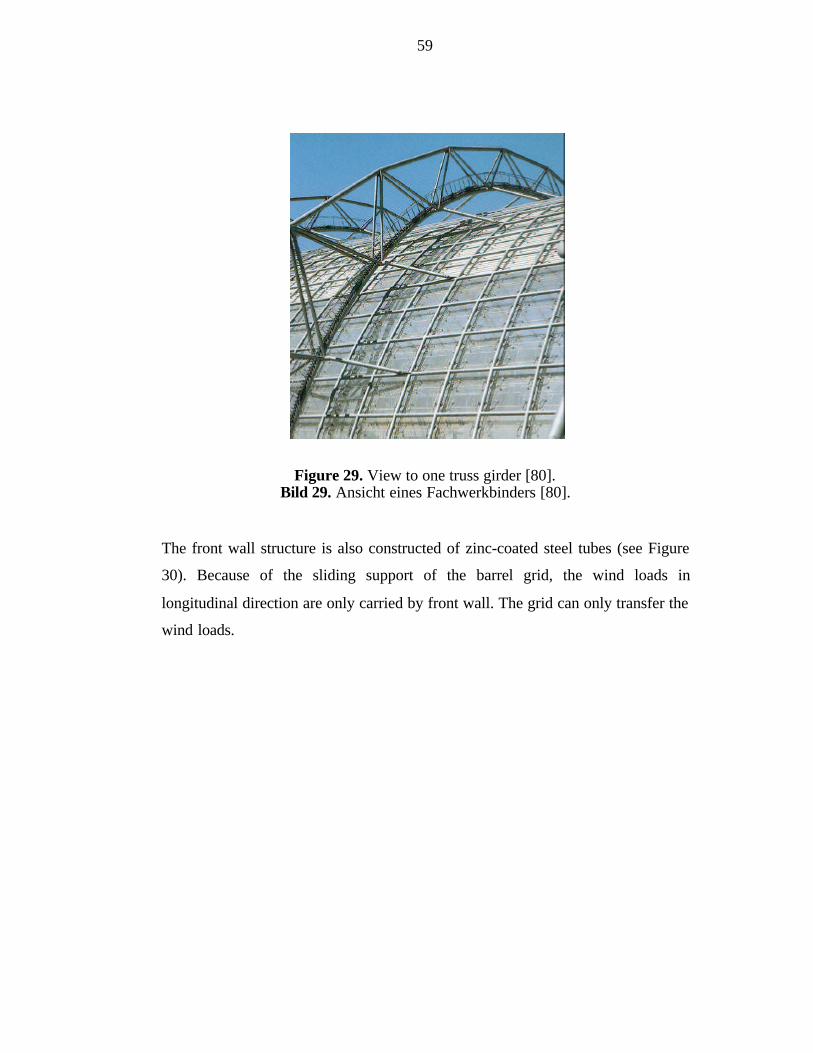
59
Figure 29. View to one truss girder [80].Bild 29. Ansicht eines Fachwerkbinders [80].
The front wall structure is also constructed of zinc-coated steel tubes (see Figure
30). Because of the sliding support of the barrel grid, the wind loads in
longitudinal direction are only carried by front wall. The grid can only transfer the
wind loads.

60
Figure 30. View to the front wall structure [82].Bild 30. Ansicht der Giebelwand-Konstruktion [82].
The main functions of the load carrying steel structure is to carry glass structures
with a minimum cost and to satisfy the architect’s image of the building. The
glass structure requires exceptionally small tolerances.
Joints [80]
The joints are constructed of stainless steel point supports (see Figure 31). The
ideal point support would have been pinned joints, because then the joint itself
does not create any stresses, when there are displacements of the glass pane. But
in suspended glass panes, pinned joints do not compensate existing longitudinal
and transversal displacements. Therefore three different kinds of joint types (see
Figures 32 and 33) were used in connecting the panes to steel structure. Support
type 1) is fixed in every direction. Support 2) allows movement in x-direction.
Support 3) allows movement in x- and y-directions. The joints allow thermal
expansion of glass panes without any stresses and prevent restrain loads caused by
displacements of load-bearing structures.
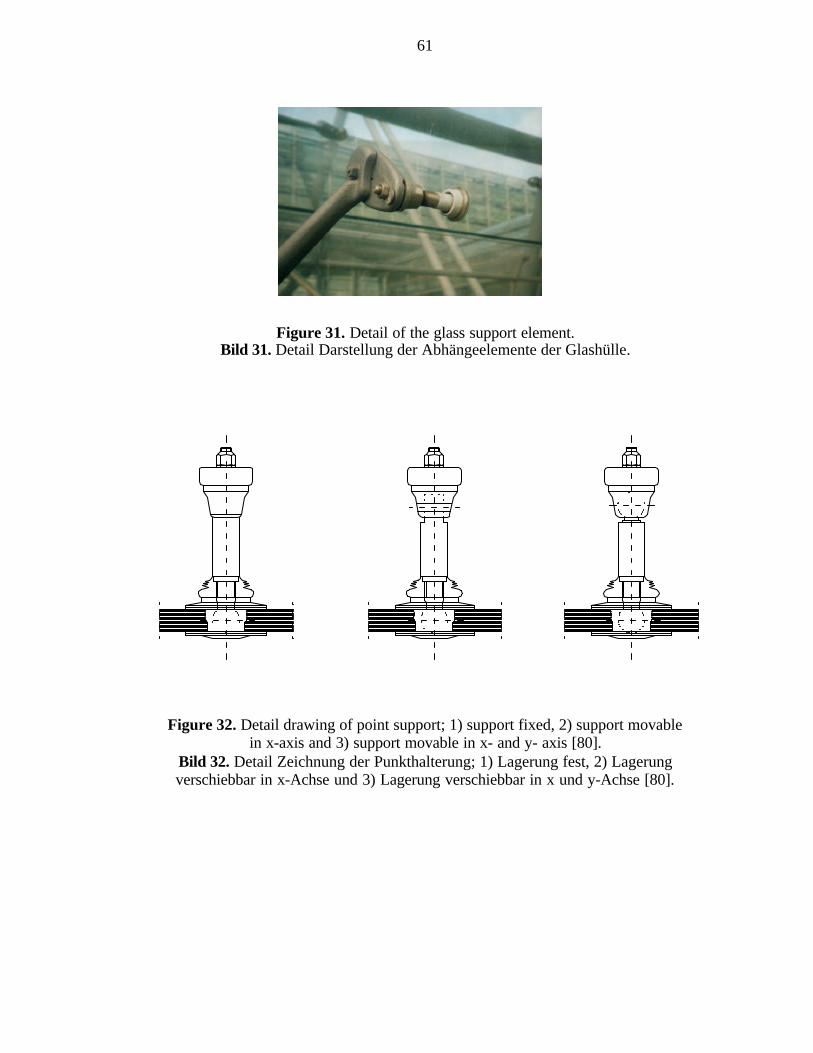
61
Figure 31. Detail of the glass support element.Bild 31. Detail Darstellung der Abhängeelemente der Glashülle.
Figure 32. Detail drawing of point support; 1) support fixed, 2) support movablein x-axis and 3) support movable in x- and y- axis [80].
Bild 32. Detail Zeichnung der Punkthalterung; 1) Lagerung fest, 2) Lagerungverschiebbar in x-Achse und 3) Lagerung verschiebbar in x und y-Achse [80].
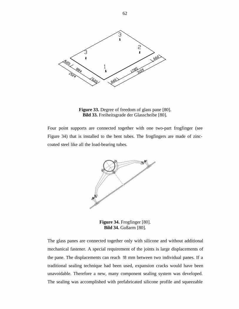
62
Figure 33. Degree of freedom of glass pane [80].Bild 33. Freiheitsgrade der Glasscheibe [80].
Four point supports are connected together with one two-part frogfinger (see
Figure 34) that is installed to the bent tubes. The frogfingers are made of zinc-
coated steel like all the load-bearing tubes.
Figure 34. Frogfinger [80].Bild 34. Gußarm [80].
The glass panes are connected together only with silicone and without additional
mechanical fastener. A special requirement of the joints is large displacements of
the pane. The displacements can reach !8 mm between two individual panes. If a
traditional sealing technique had been used, expansion cracks would have been
unavoidable. Therefore a new, many component sealing system was developed.
The sealing was accomplished with prefabricated silicone profile and squeezable
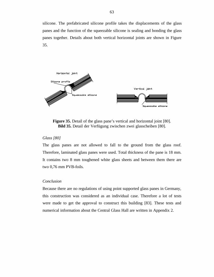
63
silicone. The prefabricated silicone profile takes the displacements of the glass
panes and the function of the squeezable silicone is sealing and bonding the glass
panes together. Details about both vertical horizontal joints are shown in Figure
35.
Figure 35. Detail of the glass pane’s vertical and horizontal joint [80].Bild 35. Detail der Verfügung zwischen zwei glasscheiben [80].
Glass [80]
The glass panes are not allowed to fall to the ground from the glass roof.
Therefore, laminated glass panes were used. Total thickness of the pane is 18 mm.
It contains two 8 mm toughened white glass sheets and between them there are
two 0,76 mm PVB-foils.
Conclusion
Because there are no regulations of using point supported glass panes in Germany,
this construction was considered as an individual case. Therefore a lot of tests
were made to get the approval to construct this building [83]. These tests and
numerical information about the Central Glass Hall are written in Appendix 2.

64
4.3 Structural Silicone Glazing
4.3.1 In General
Structural silicone glazing (SSG) is a curtain wall technique using elastomeric
glazing sealant to bond the glazing units to the supporting metal structure. It was
developed in the 1970’s in USA for multi-storey apartment houses. The goal was
to construct facades without window frames. The first glass type for SSG was
monolithic glass. Today it is possible to use all types of glass products, including
reflectively coated, laminated glass and insulating glass units.
Figure 36. Sketch of a typical two-sided (left) and four-sided (right) SSG system[84].
Bild 36. Skizze über die typischen zweiseitige (links) und vierseitige (rechts) SSGsysteme [84].
All of the load-bearing structures are behind glass plane. The load-bearing steel
frames are often constructed of large profile tubes and therefore darkened or
mirror glass is used in facades. Then the load-bearing structures are invisible from
outside and the surface of the building is more esthetic. The adhesive joint is done
by so called structural silicone. The silicone is the only possible material for
constructing structural glazed elements.
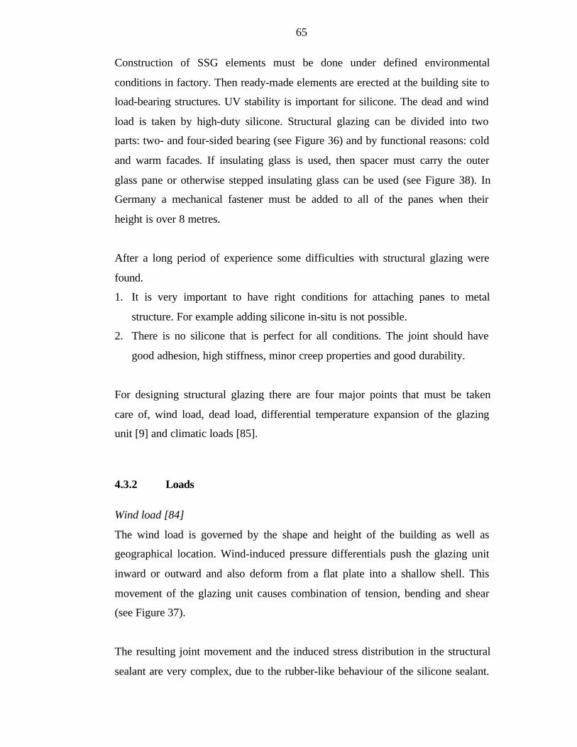
65
Construction of SSG elements must be done under defined environmental
conditions in factory. Then ready-made elements are erected at the building site to
load-bearing structures. UV stability is important for silicone. The dead and wind
load is taken by high-duty silicone. Structural glazing can be divided into two
parts: two- and four-sided bearing (see Figure 36) and by functional reasons: cold
and warm facades. If insulating glass is used, then spacer must carry the outer
glass pane or otherwise stepped insulating glass can be used (see Figure 38). In
Germany a mechanical fastener must be added to all of the panes when their
height is over 8 metres.
After a long period of experience some difficulties with structural glazing were
found.
1. It is very important to have right conditions for attaching panes to metal
structure. For example adding silicone in-situ is not possible.
2. There is no silicone that is perfect for all conditions. The joint should have
good adhesion, high stiffness, minor creep properties and good durability.
For designing structural glazing there are four major points that must be taken
care of, wind load, dead load, differential temperature expansion of the glazing
unit [9] and climatic loads [85].
4.3.2 Loads
Wind load [84]
The wind load is governed by the shape and height of the building as well as
geographical location. Wind-induced pressure differentials push the glazing unit
inward or outward and also deform from a flat plate into a shallow shell. This
movement of the glazing unit causes combination of tension, bending and shear
(see Figure 37).
The resulting joint movement and the induced stress distribution in the structural
sealant are very complex, due to the rubber-like behaviour of the silicone sealant.
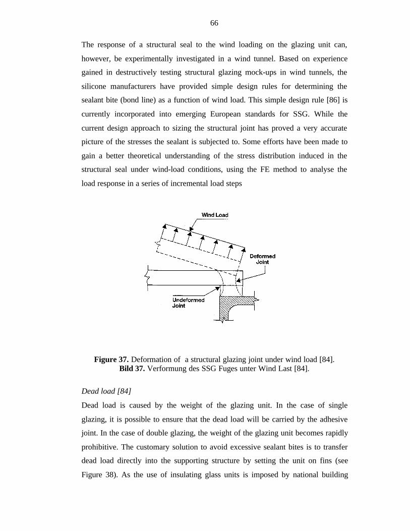
66
The response of a structural seal to the wind loading on the glazing unit can,
however, be experimentally investigated in a wind tunnel. Based on experience
gained in destructively testing structural glazing mock-ups in wind tunnels, the
silicone manufacturers have provided simple design rules for determining the
sealant bite (bond line) as a function of wind load. This simple design rule [86] is
currently incorporated into emerging European standards for SSG. While the
current design approach to sizing the structural joint has proved a very accurate
picture of the stresses the sealant is subjected to. Some efforts have been made to
gain a better theoretical understanding of the stress distribution induced in the
structural seal under wind-load conditions, using the FE method to analyse the
load response in a series of incremental load steps
Figure 37. Deformation of a structural glazing joint under wind load [84].Bild 37. Verformung des SSG Fuges unter Wind Last [84].
Dead load [84]
Dead load is caused by the weight of the glazing unit. In the case of single
glazing, it is possible to ensure that the dead load will be carried by the adhesive
joint. In the case of double glazing, the weight of the glazing unit becomes rapidly
prohibitive. The customary solution to avoid excessive sealant bites is to transfer
dead load directly into the supporting structure by setting the unit on fins (see
Figure 38). As the use of insulating glass units is imposed by national building
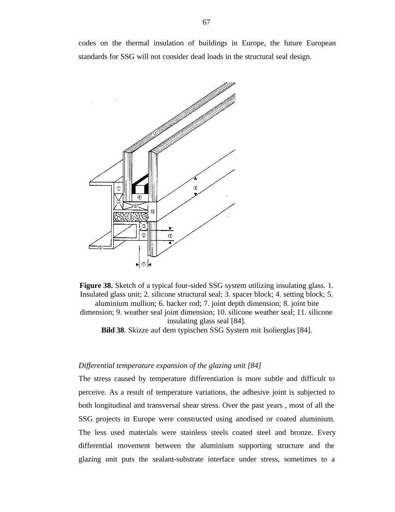
67
codes on the thermal insulation of buildings in Europe, the future European
standards for SSG will not consider dead loads in the structural seal design.
Figure 38. Sketch of a typical four-sided SSG system utilizing insulating glass. 1.Insulated glass unit; 2. silicone structural seal; 3. spacer block; 4. setting block; 5.
aluminium mullion; 6. backer rod; 7. joint depth dimension; 8. joint bitedimension; 9. weather seal joint dimension; 10. silicone weather seal; 11. silicone
insulating glass seal [84].Bild 38. Skizze auf dem typischen SSG System mit Isolierglas [84].
Differential temperature expansion of the glazing unit [84]
The stress caused by temperature differentiation is more subtle and difficult to
perceive. As a result of temperature variations, the adhesive joint is subjected to
both longitudinal and transversal shear stress. Over the past years , most of all the
SSG projects in Europe were constructed using anodised or coated aluminium.
The less used materials were stainless steels coated steel and bronze. Every
differential movement between the aluminium supporting structure and the
glazing unit puts the sealant-substrate interface under stress, sometimes to a
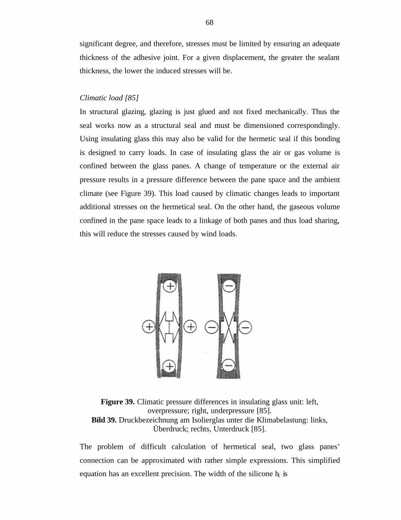
68
significant degree, and therefore, stresses must be limited by ensuring an adequate
thickness of the adhesive joint. For a given displacement, the greater the sealant
thickness, the lower the induced stresses will be.
Climatic load [85]
In structural glazing, glazing is just glued and not fixed mechanically. Thus the
seal works now as a structural seal and must be dimensioned correspondingly.
Using insulating glass this may also be valid for the hermetic seal if this bonding
is designed to carry loads. In case of insulating glass the air or gas volume is
confined between the glass panes. A change of temperature or the external air
pressure results in a pressure difference between the pane space and the ambient
climate (see Figure 39). This load caused by climatic changes leads to important
additional stresses on the hermetical seal. On the other hand, the gaseous volume
confined in the pane space leads to a linkage of both panes and thus load sharing,
this will reduce the stresses caused by wind loads.
Figure 39. Climatic pressure differences in insulating glass unit: left,overpressure; right, underpressure [85].
Bild 39. Druckbezeichnung am Isolierglas unter die Klimabelastung: links,Überdruck; rechts, Unterdruck [85].
The problem of difficult calculation of hermetical seal, two glass panes’
connection can be approximated with rather simple expressions. This simplified
equation has an excellent precision. The width of the silicone hc is
69
des
sc
pah
σ=
2 (2)
where
p = load [N/mm2]
as = length of the short side of the glass pane [mm]
ódes = design load [N/mm2]
The equation does not include shear load but shear has meaning only with bigger
panes, where climatic loads are not decisive.
4.3.3 Silicone [87]
Silicone rubber is a macromolecular polymer composed from –Si-O- radicals and
organic side groups that are attached to the silicone atoms. The mechanical
properties of silicone are characteristic of rubber like elastomers. In particular,
silicone is approximately incompressible and sustains large elastic deformations
prior fracture in conjunction with a distinctive non-linear stress-strain
characteristic as shown exemplary in Figure 40. In comparison to other rubber
like materials the elastic properties vary only slightly with temperature and silicon
rubber can be used over a wide temperature range.

70
Figure 40. Tension stress-strain curve for medium modulus structural siliconesealant [88].
Bild 40. Zugspannung–Dehnung Kurve für die medium E-ModulKonstruktionsilikondichtungsmasse [88].
4.3.4 Safety of Structural Glazing [89]
Overall safety of structural glazing is by far a little researched area. Safety of
different components is often calculated, but how the components act together is
not researched. Overall safety of structural glazing is determined with the help of
probability theory. In Germany DIN code requires mechanical fasteners to hold
glass panes above 8 metre in glass facades. In other countries like France or USA
there is no such requirement. Therefore the necessity of the mechanical fastener
has been researched. Research is done according to safety factors of DIN codes.
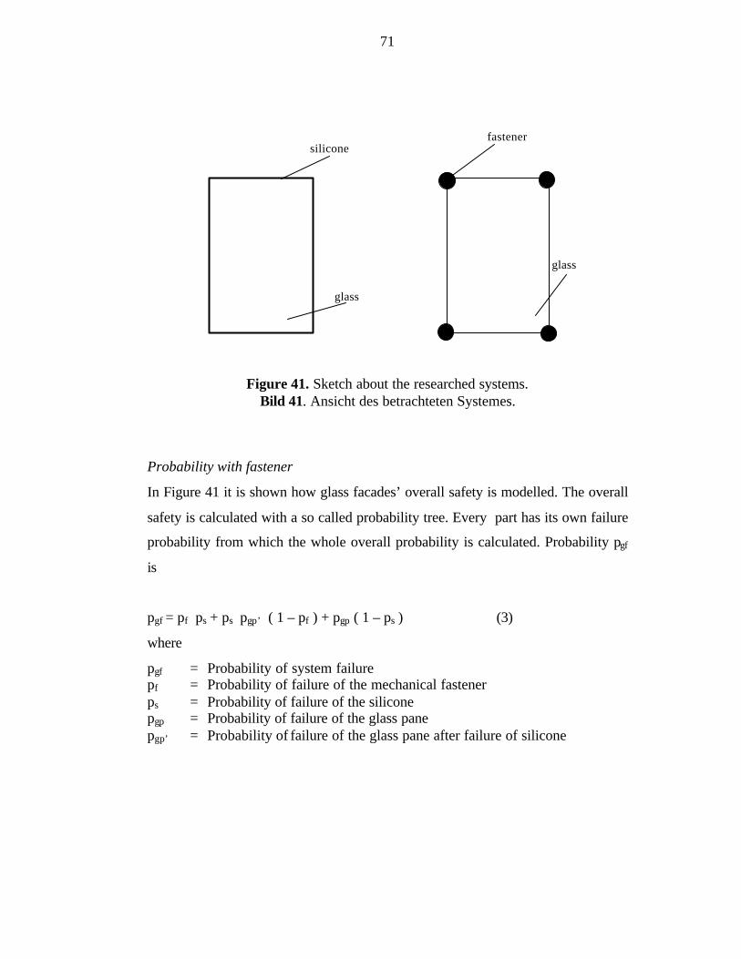
71
Figure 41. Sketch about the researched systems.Bild 41. Ansicht des betrachteten Systemes.
Probability with fastener
In Figure 41 it is shown how glass facades’ overall safety is modelled. The overall
safety is calculated with a so called probability tree. Every part has its own failure
probability from which the whole overall probability is calculated. Probability pgf
is
pgf = pf ps + ps pgp’ ( 1 – pf ) + pgp ( 1 – ps ) (3)
where
pgf = Probability of system failurepf = Probability of failure of the mechanical fastenerps = Probability of failure of the siliconepgp = Probability of failure of the glass panepgp’ = Probability of failure of the glass pane after failure of silicone
silicone
glass
fastener
glass
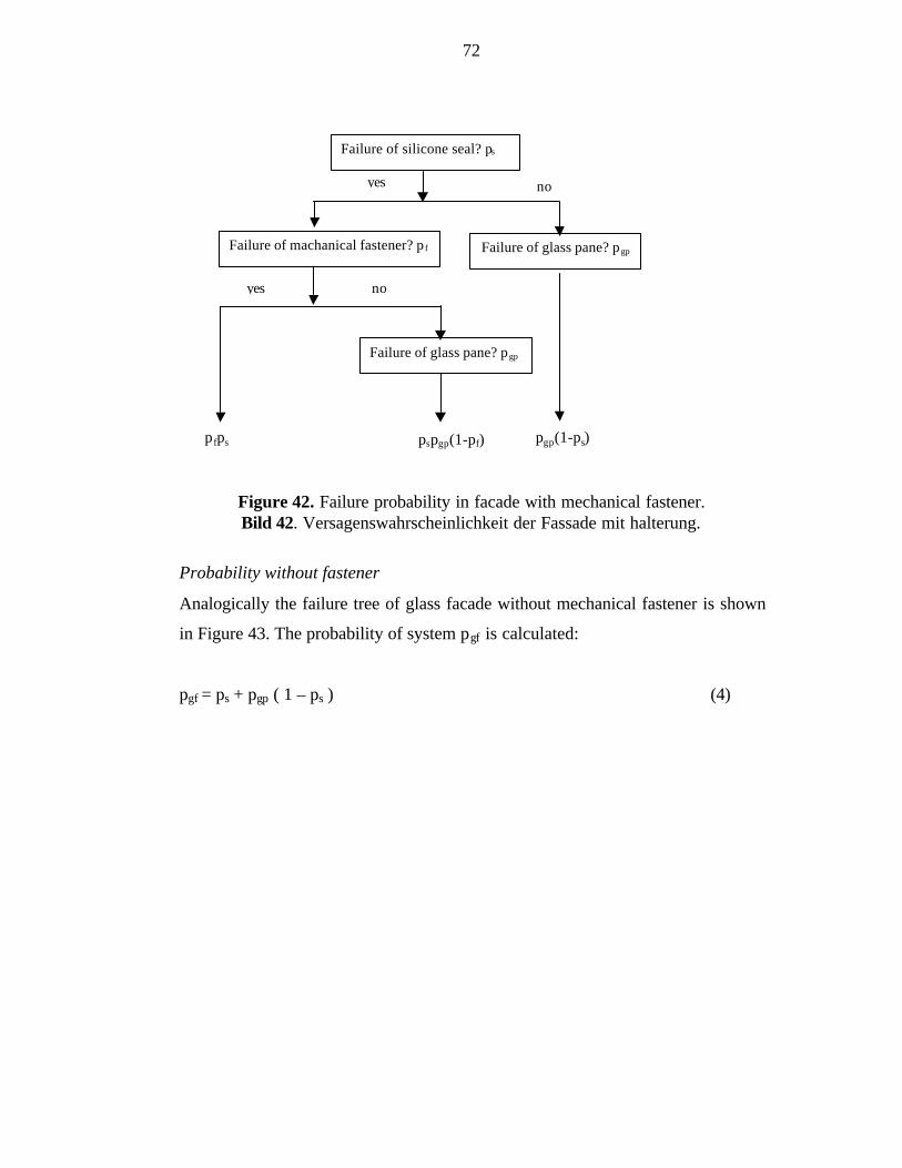
72
Figure 42. Failure probability in facade with mechanical fastener.Bild 42. Versagenswahrscheinlichkeit der Fassade mit halterung.
Probability without fastener
Analogically the failure tree of glass facade without mechanical fastener is shown
in Figure 43. The probability of system pgf is calculated:
pgf = ps + pgp ( 1 – ps ) (4)
Failure of silicone seal? ps
Failure of glass pane? pgp
Failure of glass pane? pgpFailure of machanical fastener? p f
yes no
yes no
p fps pgp(1-ps)pspgp(1-pf)
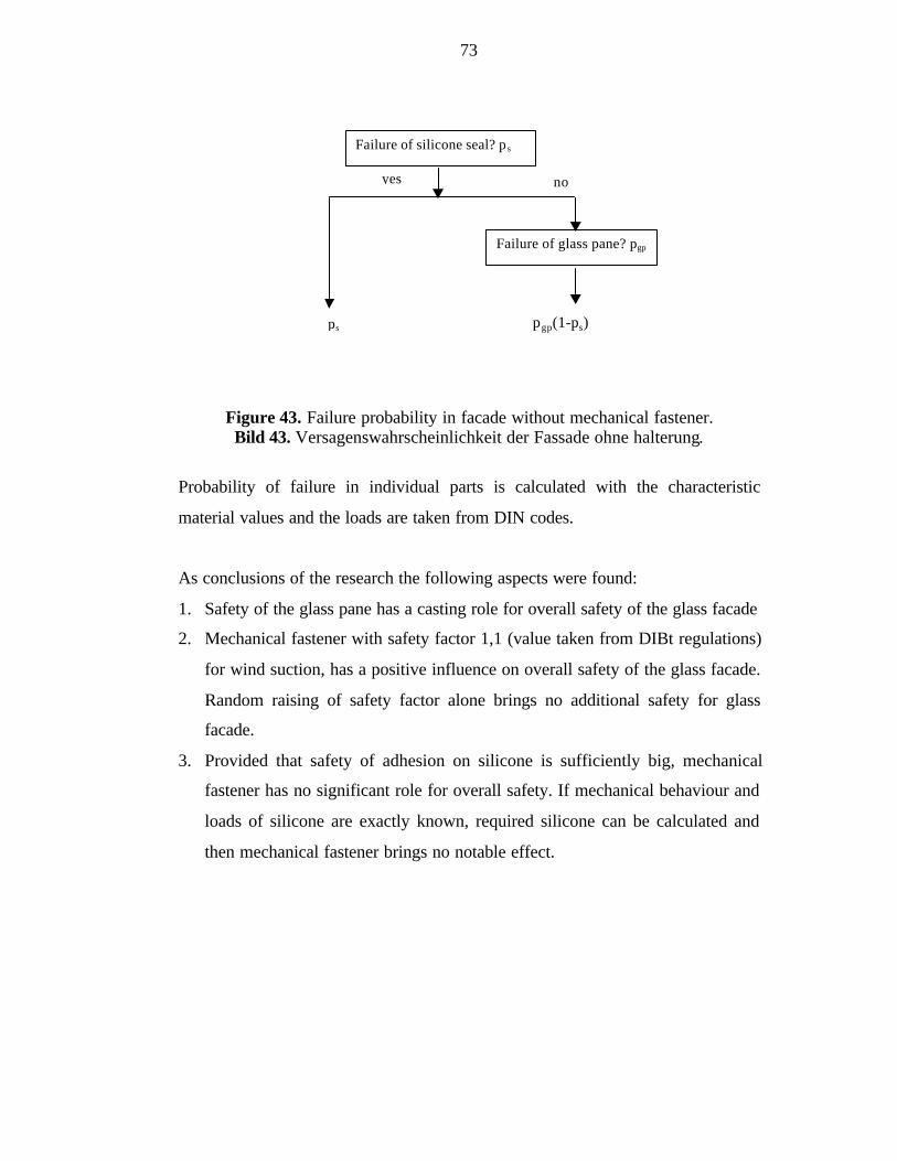
73
Figure 43. Failure probability in facade without mechanical fastener.Bild 43. Versagenswahrscheinlichkeit der Fassade ohne halterung.
Probability of failure in individual parts is calculated with the characteristic
material values and the loads are taken from DIN codes.
As conclusions of the research the following aspects were found:
1. Safety of the glass pane has a casting role for overall safety of the glass facade
2. Mechanical fastener with safety factor 1,1 (value taken from DIBt regulations)
for wind suction, has a positive influence on overall safety of the glass facade.
Random raising of safety factor alone brings no additional safety for glass
facade.
3. Provided that safety of adhesion on silicone is sufficiently big, mechanical
fastener has no significant role for overall safety. If mechanical behaviour and
loads of silicone are exactly known, required silicone can be calculated and
then mechanical fastener brings no notable effect.
Failure of silicone seal? p s
Failure of glass pane? pgp
yes no
pgp(1-ps)ps
74
5 CONCLUSIONS
This paper has presented gathering of known joints and fastenings in steel-glass
facades including matter depending national construction codes and material
properties of glass, steel, stainless steel and aluminium. Various supporting
structures of steel-glass facades have been described. Also one example in which
a glass building, the New Leipzig Fair, has been examined.
Glass has become a major element in designing modern commercial or public
buildings. Load-bearing structures are wanted to be delicate systems with a
transparent feel. The use of steel in load-bearing structures improves the
transparency of facades because it has been possible to keep the load-bearing
structure slender.
The main aspect in designing steel and glass joints is to consider the special
material properties and behaviour of glass. Glass fractures brittlely without a
forewarning. These properties and behaviour concern normal float glass as well as
laminated glass and safety glass. Glass cannot have local plastic deformations and
when glass is in direct contact with steel, small inequalities of steel can cause a
crack in glass or break it. Therefore, a softer material always has to be used
between steel and glass. The requirements of designing load-bearing structures
have normally been gotten from either the glass supplier or the producer of glass
pane elements, who both are thereby responsible for the strength and functionality
of the fastening.
One of the new connection types, point support, is used very little in Finland.
Point supports are mainly constructed of stainless steel, sometimes also used
corrosion protected steel is used. The main requirements of supports are
functionality with glass and very small tolerances. The requirement of small
tolerances concern also the load-bearing structures. Point supports are affected by
high stresses in drilling area, restraint loads caused by temperature and in
insulation glass panes possibly even additional stresses caused by many-sheet-
75
glazing. Difficulties of Finnish companies in producing point supports is a small
ratio of potential market and developing costs.
The fire resistance requirements of joints and fasteners are same as for the whole
load-bearing structure. Fire protection of glass covered structures is essential in
big open spaces. Today standard temperature-time curve is used, which leads to
uneconomical solutions because of the fast rise in temperature. New SRMK E1
allows simulation of fire, but there are no rules by authorities for using fire
simulation programmes. Also, the simulation programmes are only applicable to
research use because the programmes give false answers if they are not used
correctly.
Development of transparent facades has been and is still fast and regulations are
done much slower than the development would require. In Finland, this causes
uncertainty of safety in designing and constructing of steel-glass facades. In
Germany, lack of regulations causes lots of testing and additional work to get the
licence to build. Therefore research information should be gathered together and
regulations should be made. The regulations should consist overall behaviour of
facades including load-bearing structures, joints and glass panes. The task is not
easy because structural solutions of glazed facades are often so unique that
applying some regulations might lead to bad situation in the end.
The safety of individual parts of the steel-glass facades; load-bearing structures,
profile parts, cladding parts and fastening parts are today rather well known. In
further research overall safety of steel-glass facade should be clarified. Also the
influence of different installation ways on the safety of the glass panes should be
investigated.
76
REFERENCES:
[1] Hemmilä K., Lämpötilat kahdessa valokatossa. Technical Research Centre
of Finland (VTT), Research notes 1380, Espoo 1992, Finland (in Finnish).
[2] Keski-Rahkonen O., Björkman J., Valokatteisten tilojen palotekniikkaa.
Technical Research Centre of Finland (VTT), Research notes 1381, Espoo
1992, Finland (in Finnish).
[3] Lahdenperä P., Tuoteosakaupan toimintamalli, Valoaläpäisevät rakenteet.
Technical Research Centre of Finland (VTT), Research notes 1382, Espoo
1992, Finland (in Finnish).
[4] Hassinen P., Mantere L., Saarimaa J., Hemmilä K., Rautiainen L.,
Valoaläpäisevien rakenteiden arviointi; Menetelmiä ja koetuloksia,
Technical Research Centre of Finland (VTT), Research notes 1383, Espoo
1992, Finland (in Finnish).
[5] Hassinen P., Mantere L., Rautiainen L., Nissilä R., Hemmilä K.,
Valoaläpäisevien rakenteiden uudet ratkaisut. Technical Research Centre
of Finland (VTT), Research notes 1384, Espoo 1992, Finland (In Finnish).
[6] Lasirakentaja T 1997, Finland (in Finnish).
[7] Techen H., Fügetechnik für den konstruktiven Glasbau, Doctoral Thesis,
Darmstadt 1997, Germany (in German).
[8] Sagmeister B., Tragende Bauteile aus Glas, Doctoral Thesis, Research
notes, booklet 4, Darmstadt 1993, Germany (in German).
[9] Sedlacek G., Blank K., Güsgen J., Glass in structural engineering, The
Structural Engineer, Vol. 73, No 2, January 1995 pp. 17-22.
[10] Compagno A, Intelligent Glass Façades, Basel 1996, Switzerland.
[11] Association of Finnish Civil Engineers RIL 167-1 Handbook on Steel
Structures I, Helsinki 1988, Finland (in Finnish).
[12] Sonderdruck 862, Allgemeine bauaufsichtliche Zulassung Z-30.3-6,
Construction Institute of Germany (DIBt), 1998, Germany (in German).
[13] Outinen J., Researcher in Laboratory of Steel Structures, Discussion
15.9.1999.
77
[14] Aluminium Vol. II. Design and Application, American Society for Metals,
1967 USA.
[15] Leppävuori E., Prokki H., Kanerva P., Vähäkallio P., Rakennusaineet,
Otakustantamo, Helsinki 1996, Finland (in Finnish).
[16] Askeland D., R., The SCIENCE and ENGINEERING of MATERIALS,
CHAPMAN& HALL, London 1990, 880 pages.
[17] Rice P., Hugh D., Structural Glass, E & FN SPON, London 1995,
England.
[18] Hess R., Tragendes Glas, Stahlbau no. 4 1998, Germany pp. 231-251 (in
German).
[19] Klinkenberg A., Jäger B., Saal H., Untersuchungen zur statisch optimalen
Halterposition bei punktgestützten Glastafeln, Stahlbau 67 (1998) No 4,
pp. 275-280, Germany (in German).
[20] Teräs julkisessa rakentamisessa, Steel in public construction, The Finnish
Constructional Steelwork Association (FCSA), Rakennustieto Oy, 1998
Helsinki, Finland (in Finnish).
[21] Eurocode 1 (ENV 1991), Part 1: Basis of Design, Background
Documentation, European Convention for Constructional Steelwork
(ECCS), Working Document, March 1996.
[22] Charlier H., Regeln für tragendes Glas, Bauaufsichtliche Anforderungen
an Glaskonstruktionen Teil 1, Deutsches IngenieurBlatt, May 1998,
Germany, pp. 16-23 (in German).
[23] Internet page of DIN, http://www.din.de/portrait/baustein.html (in
German).
[24] Internet page of Construction Institute of Germany (DIBt),
http://www.dibt.de/ (in German).
[25] Internet page of Der Deutsche Ausschuß für Stahlbau DASt,
http://www.deutscherstahlbau.de/dast/documents/dast_frame.html (in
German).
[26] Fassadentechnik, Aussenwandbekleidung aus Metall, Naturstein, Glas,
Keramik, Faserzement Neue DIN-Normen, Verein Deutscher Ingenieure
(VDI) Berichte 710, Essen 1989, Germany (in German).

78
[27] Wohlfahrt R., Determination of the load bearing capacity of large-scale
glass panes by detail tests, Otto Graf Journal, no. 5 1994, Germany, pp.
174-182.
[28] Technische Regeln für die Verwendung von linienförmig gelagerten
Vertikalverglasungen, Report of DIBt, Design version, May 1997
Germany (in German).
[29] Technische Regeln für die Verwendung von linienförmig gelagerten
Überkopfverglasungen, Report of DIBt, 1996 Germany (in German).
[30] Wörner J. D., Bauen mit Glas: Berechnung, Bemessung, Konstruktion,
OTTI-Seminarband: „Glas im Bauwesen“, OTTI-Regensburg 1996,
Germany (in German).
[31] Charlier H., Glas muß stark und sicher sein, Bauaufsichtliche
Anforderungen an Glaskonstruktionen Teil 2, Deutsches IngenieurBlatt,
June 1998, Germany, pp. 22- 28 (in German).
[32] Dichstoffe für Verglasungen und Anschlußfugen, Arten, Eigenschaften,
Anwendung, Verabeitung, Technical guideline of glazing industry no. 1 ,
Verlag Karl Hofmann, Schondorf 1986, Germany (in German).
[33] Windlast und Glasdicke, Dickenwahl von glasscheiben in Abhängigkeit
von der Windlast, Technical guideline of glazing industry no. 2 , Verlag
Karl Hofmann, Schondorf 1987, Germany (in German).
[34] Klotzungsrichtlinien für ebene Glasscheiben, Technical guideline of
glazing industry no. 3 , Verlag Karl Hofmann, Schondorf 1979, Germany
(in German).
[35] Verzeichnis der Normen für die Arbeitsgebiete des Glasers und
Fensterbauers, Technical guideline of glazing industry no. 4, Verlag Karl
Hofmann, Schondorf 1987, Germany (in German) (is only available in
loose-leaf publication from glazing industry in Hadamar).
[36] Ganzglaskonstruktionen mit Glaszement-Verbindungen, Technical
guideline of glazing industry no. 6 , Verlag Karl Hofmann, Schondorf
1987, Germany (in German).
79
[37] Richtlinien für den Bau und Verglasung von Metallrahmen-Schaufenstern
und gleichartigen Konstruktionen, Technical guideline of glazing industry
no. 9, Verlag Karl Hofmann, Schondorf 1980, Germany (in German).
[38] Fachliche Begriffe aus dem Berufsbereich des Glaserhandwerks,
Technical guideline of glazing industry no. 10, Verlag Karl Hofmann,
Schondorf 1988, Germany (in German).
[39] Fensterwände – Bemessung und Ausführung, Erläuterungen zu DIN 18
056, Technical guideline of glazing industry no. 12, Verlag Karl Hofmann,
Schondorf 1977, Germany (in German).
[40] Verglasungen mit Dichtprofilen, Technical guideline of glazing industry
no. 13, Verlag Karl Hofmann, Schondorf 1987, Germany (in German).
[41] Glas im Bauwesen – Einteilung der Glaserzeugnisse, Technical guideline
of glazing industry no. 14, Verlag Karl Hofmann, Schondorf 1981,
Germany (in German).
[42] Fenster und Fensterwände für Hallenbäder, Richtlinien für Ausführung
und die Verglasung mit Mehrscheiben-Isolierglas, Technical guideline of
glazing industry no. 16, Verlag Karl Hofmann, Schondorf 1987, Germany
(in German).
[43] Verglasen mit Mehrscheiben-Isolierglas, einschließlich Erläuterungen zu
DIN 18 545 Teil 1-3, Technical guideline of glazing industry no. 17,
Verlag Karl Hofmann, Schondorf 1986, Germany (in German).
[44] Umwehrungen mit Glas, Konstruktionshilfen anhand von Bewährten
Beispieln aus der Praxis, Technical guideline of glazing industry no. 18,
Verlag Karl Hofmann, Schondorf 1985, Germany (in German).
[45] Überkopf-Verglasungen, Bestandsaufnahme der Ausführungsvorschriften,
Dickenwahl von Glasscheiben für nicht senkrechten Einbau, Technical
guideline of glazing industry no. 19, Verlag Karl Hofmann, Schondorf
1988, Germany (in German).
[46] Montage von fenstern mit Anwendungs- und Einbaubeispielen, Technical
guideline of glazing industry no. 20, Verlag Karl Hofmann, Schondorf
1987, Germany (in German).
80
[47] Internet page of Finnish Standard Association (SFS),
http://www.sfs.fi/english.html.
[48] Internet page of The Finnish Ministry of the Environment,
http://www.vyh.fi/raken/rakmk/rakmaar.htm (in Finnish).
[49] SRMK C3, Thermal insulation, Regulations 1985, The Finnish Ministry of
the Environment, Helsinki 1985 (in Finnish).
[50] SRMK C1, Sound insulation and noise abatement in building, Regulations
and guidelines 1998, The Finnish Ministry of the Environment, Helsinki
1998 (in Finnish).
[51] SRMK C5, Sound insulation, Guidelines 1985, The Finnish Ministry of
the Environment, Helsinki 1985 (in Finnish).
[52] SRMK E1, Structural fire safety in buildings, Regulations and guidelines
1997, The Finnish Ministry of the Environment, Helsinki 1997 (in
Finnish).
[53] Rakennusten paloturvallisuus & Paloturvallisuus korjausrakentamisessa,
The Finnish Ministry of the Environment, Helsinki 1998 (in Finnish).
[54] Valkama T., The use of zone model simulation of fire in an insurance
company, master’s thesis, Espoo 1998, 68p. (in Finnish).
[55] SRMK B7, Steel structures, Guidelines 1996, The Finnish Ministry of the
Environment, Helsinki 1996 (in Finnish).
[56] Association of Finnish Civil Engineers RIL 198-1993, Valoaläpäisevät
rakenteet, Transparent Structures, 1993 Hanko, Finland (in Finnish).
[57] Guide technique UEAtc pour l’agrément des vitrages exterieurs colles.
1992 (in French).
[58] Ritchie I., Constructing with glass, Stahlbau no. 4 1998, Germany pp. 225-
230.
[59] Schüco International, Aluminium-Profilfassaden-Systeme, FW50, FW 50 S,
SK 60V und “Schüco BF”, brochure, 1998, (in German).
[60] Piirainen H., Magnus Malmberg Oy, 5.10.1999, discussion.
[61] Malkakorpi P., Suuren Metallirunkoisen Lasifasadin Suunnittelu,
Engineering Thesis, Helsinki Institute of Technology, 1997 Helsinki, 18p
(in Finnish).
81
[62] Wagner R., Aufgelöste Tragwerke für großflächige Fassaden, Der
Architekt, no. 5 1995, Germany, pp. 308-312 (in German).
[63] Pask D., The Korean World Trade Centre Glass Walls. New Steel
Construction, The British Constructional Steelwork Association Ltd.,
February/March 1999, pp. 18-19.
[64] Knaack U., Konstruktiver Glasbau, Verlagsgesellschaft Rudolf Müller,
Köln 1998, Germany (in German).
[65] Schüco International, Schüco – Doppelfassade, brochure, Schüco-Objekt-
Report, Germany (in German).
[66] Air Quality and thermal Comfort in a Naturally Ventilated School Building
with Glazed Double Facade, Simulation study of EMPA – a Research
Institute within the Swiss Federal Institute of Technology (ETH),1998
Switzerland.
[67] Kommunikatiivinen miljöö vaativalle työlle – Nokia-talo Keilalahdessa,
Lasirakentaja, no. 2 1997, Finland pp. 20-24 (in Finnish).
[68] Beilicke G., Moritzhof Chemnitz – Stahl, Glas und Brandschutz,
Presentation in “Deutscher Stahlbautag October 15th 1998”, Leipzig,
Germany (in German).
[69] Wathling K.-D., Stahl-Glas-Konstruktion zur Bildung von Brand- und
Rauchabschnitten, Stahlbau no. 2 1996, Germany pp. 97-102 (in German).
[70] Rakennustuotteiden palotekninen hyväksyntä, The Finnish Ministry of the
Environment, Helsinki 1998 (in Finnish).
[71] Güsgen J., Blank K., Sedlacek G., Zusammenarbeit zwischen Stahl und
Glas, Presentation, German Steel Construction Federation (DSTV) 6.
September 1996, Cologne, Germany (in German)
[72] Schulz C., Seger P., Glas am Bau I, Konstruktion von Glasfassaden,
Deutsches Architektenblatt (DAB), no. 3 1993, Germany pp. 441-447, (in
German).
[73] Kapillarglas GmbH, Okapoint, Point supported system for insulating
glass, brochure.
[74] Lehmann R., Auslegung punktgehaltener Gläser, Stahlbau no. 4 1998,
Germany pp. 270-274 (in German).
82
[75] Wörner J.-D., Konstruktiver Glasbau, Grundlagen, Bemessung und
Konstruktion, Presentation in “Glas im Bauwesen” seminar 20.-21.
October 1998, OTTI Regensburg, Germany (in German).
[76] Kapillarglas GmbH, Okalux, Lichtstreundes Isolierglas, brochure.
[77] Kutterer M., Görzig R., Sobek W., Bauen mit Glas, Glasfestigkeit im
Bohrungsbereich, Research Report 1/97, Institute of Lightweight
Structures, University of Stuttgart, Stuttgart 1997, Germany (in German).
[78] DIN 51 110 Part 3, Prüfung von keramischen Hochleistungswerkstoffen,
Germany (in German).
[79] Neue Messe Leipzig, Stahl und Form, Stahl-Informations-Zentrum, 1997
Düsseldorf, Germany (in German, partly in English).
[80] Neue Messe Leipzig, “Zentrale Eingangshalle”, brochure (in German).
[81] Klimke H., Stutzki Ch., Ludwig J., Vasiliu M., Hodis W., Die Glashalle
der Neuen Messe Leipzig, Bauingenieur 71, 1996, Germany, pp. 401-411
(in German).
[82] Marg V., Neue Messe Leipzig, Basel 1997, Switzerland (in German).
[83] Wörner J.-D., Pfeiffer R., Techen H., Zentrale Eingangshalle der Neuen
Messe Leipzig, Gesichtspunkte der Glaskonstruktion, Fassade . Façade no
2 1996, Germany, pp. 15-18 (in German).
[84] Iker J., Wolf A. T., Secondary stresses induced by shear movement in
structural glazing sealants. Materials and Structures, vol. 25, 1992 pp.
137-144.
[85] Feldmeier F., Belastung des tragenden Randverbundes von Isolierglas bei
Structural Glazing durch klimatische Einflüsse, Research Report, Institut
für Fenstertechnik e.v. Rosenheim, IRB Verlag, 1995 Stuttgart, Germany
(in German).
[86] Haugsby M. H., Schoenherr W. J., Carbary L. D., Schmidt C. M., Methods
for calculating structural silicone sealant joint dimensions, Science and
Technology of Glazing, American Society for Testing and Materials
(ASTM) STP 1054, 1989, pp. 46-57.
83
[87] Krüger G., Zhu H., Determination of material properties in structural
sealant glazing applications, Otto-Graf-Journal, no. 4 1993, Germany pp.
192-209.
[88] Schmidt C. M., Schoenherr W. J., Carbary L. D., Takish M. S.,
Performance Properties of Silicone Structural Adhesives, Science and
Technology of Glazing, American Society for Testing and Materials
(ASTM) STP 1054, 1989, pp. 22-45.
[89] Shen X., Techen H., Wörner J.-D., Sicherheit von Glasfassaden,
Fraunhofer IRB Verlag, Stuttgart 1996, Germany (in German).
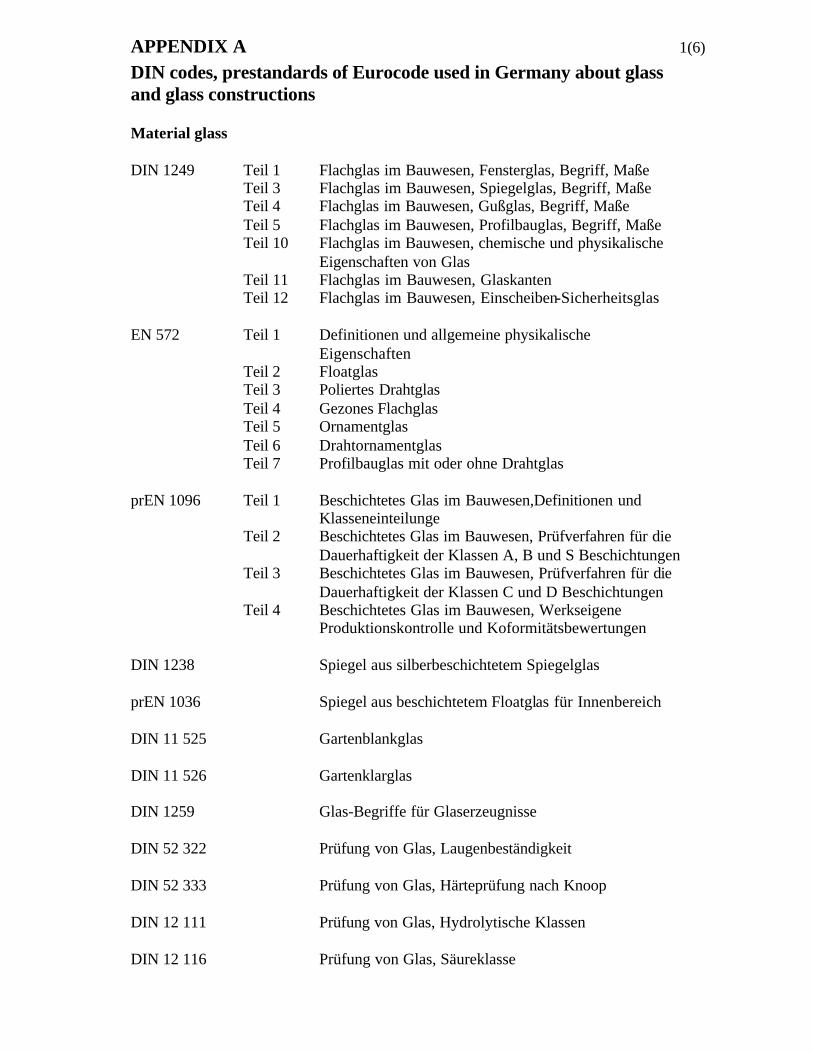
APPENDIX A 1(6)
DIN codes, prestandards of Eurocode used in Germany about glassand glass constructions
Material glass
DIN 1249 Teil 1 Flachglas im Bauwesen, Fensterglas, Begriff, MaßeTeil 3 Flachglas im Bauwesen, Spiegelglas, Begriff, MaßeTeil 4 Flachglas im Bauwesen, Gußglas, Begriff, MaßeTeil 5 Flachglas im Bauwesen, Profilbauglas, Begriff, MaßeTeil 10 Flachglas im Bauwesen, chemische und physikalische
Eigenschaften von GlasTeil 11 Flachglas im Bauwesen, GlaskantenTeil 12 Flachglas im Bauwesen, Einscheiben-Sicherheitsglas
EN 572 Teil 1 Definitionen und allgemeine physikalischeEigenschaften
Teil 2 FloatglasTeil 3 Poliertes DrahtglasTeil 4 Gezones FlachglasTeil 5 OrnamentglasTeil 6 DrahtornamentglasTeil 7 Profilbauglas mit oder ohne Drahtglas
prEN 1096 Teil 1 Beschichtetes Glas im Bauwesen,Definitionen undKlasseneinteilunge
Teil 2 Beschichtetes Glas im Bauwesen, Prüfverfahren für dieDauerhaftigkeit der Klassen A, B und S Beschichtungen
Teil 3 Beschichtetes Glas im Bauwesen, Prüfverfahren für dieDauerhaftigkeit der Klassen C und D Beschichtungen
Teil 4 Beschichtetes Glas im Bauwesen, WerkseigeneProduktionskontrolle und Koformitätsbewertungen
DIN 1238 Spiegel aus silberbeschichtetem Spiegelglas
prEN 1036 Spiegel aus beschichtetem Floatglas für Innenbereich
DIN 11 525 Gartenblankglas
DIN 11 526 Gartenklarglas
DIN 1259 Glas-Begriffe für Glaserzeugnisse
DIN 52 322 Prüfung von Glas, Laugenbeständigkeit
DIN 52 333 Prüfung von Glas, Härteprüfung nach Knoop
DIN 12 111 Prüfung von Glas, Hydrolytische Klassen
DIN 12 116 Prüfung von Glas, Säureklasse
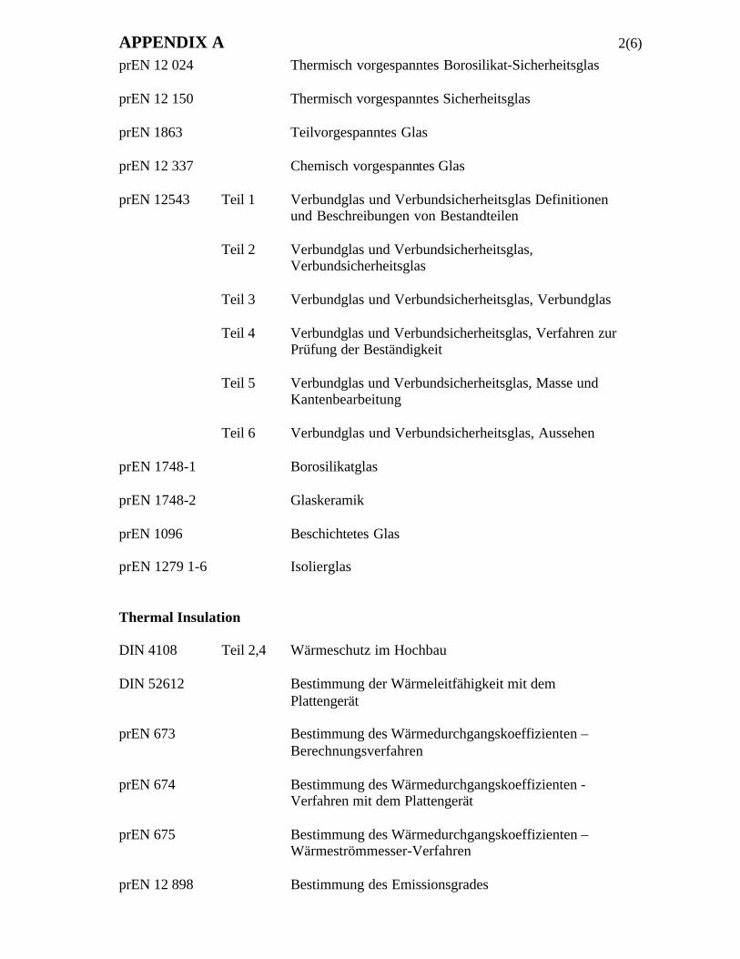
APPENDIX A 2(6)
prEN 12 024 Thermisch vorgespanntes Borosilikat-Sicherheitsglas
prEN 12 150 Thermisch vorgespanntes Sicherheitsglas
prEN 1863 Teilvorgespanntes Glas
prEN 12 337 Chemisch vorgespanntes Glas
prEN 12543 Teil 1 Verbundglas und Verbundsicherheitsglas Definitionenund Beschreibungen von Bestandteilen
Teil 2 Verbundglas und Verbundsicherheitsglas,Verbundsicherheitsglas
Teil 3 Verbundglas und Verbundsicherheitsglas, Verbundglas
Teil 4 Verbundglas und Verbundsicherheitsglas, Verfahren zurPrüfung der Beständigkeit
Teil 5 Verbundglas und Verbundsicherheitsglas, Masse undKantenbearbeitung
Teil 6 Verbundglas und Verbundsicherheitsglas, Aussehen
prEN 1748-1 Borosilikatglas
prEN 1748-2 Glaskeramik
prEN 1096 Beschichtetes Glas
prEN 1279 1-6 Isolierglas
Thermal Insulation
DIN 4108 Teil 2,4 Wärmeschutz im Hochbau
DIN 52612 Bestimmung der Wärmeleitfähigkeit mit demPlattengerät
prEN 673 Bestimmung des Wärmedurchgangskoeffizienten –Berechnungsverfahren
prEN 674 Bestimmung des Wärmedurchgangskoeffizienten -Verfahren mit dem Plattengerät
prEN 675 Bestimmung des Wärmedurchgangskoeffizienten –Wärmeströmmesser-Verfahren
prEN 12 898 Bestimmung des Emissionsgrades
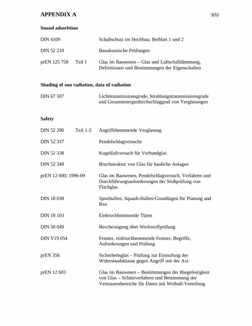
APPENDIX A 3(6)
Sound adsorbtion
DIN 4109 Schallschutz im Hochbau; Beiblatt 1 und 2
DIN 52 210 Bauakustische Prüfungen
prEN 125 758 Teil 1 Glas im Bauwesen – Glas und Luftschalldämmung,Definitionen und Bestimmungen der Eigenschaften
Shading of sun radiation, data of radiation
DIN 67 507 Lichttransmissionsgrade, Strahlungstransmissionsgradeund Gesamtenergiedurchschlaggrad von Verglasungen
Safety
DIN 52 290 Teil 1-5 Angriffshemmende Verglasung
DIN 52 337 Pendelschlagversuche
DIN 52 338 Kugelfallversuch für Verbundglas
DIN 52 349 Bruchstruktur von Glas für bauliche Anlagen
prEN 12 600; 1996-09 Glas im Bauwesen, Pendelschlagversuch, Verfahren undDurchführungsanforderungen der Stoßprüfung vonFlachglas
DIN 18 038 Sporthallen, Squash-Hallen-Grundlagen für Planung undBau
DIN 18 103 Einbruchhemmende Türen
DIN 50 049 Bescheinigung über Werkstoffprüfung
DIN V19 054 Fenster, einbruchhemmende Fenster, Begriffe,Anforderungen und Prüfung
prEN 356 Sicherheitsglas – Prüfung zur Einstufung derWiderstandsklasse gegen Angriff mit der Axt
prEN 12 603 Glas im Bauwesen – Bestimmungen der Biegefestigkeitvon Glas – Schätzverfahren und Bestimmung derVertrauensbereiche für Daten mit Weibull-Verteilung
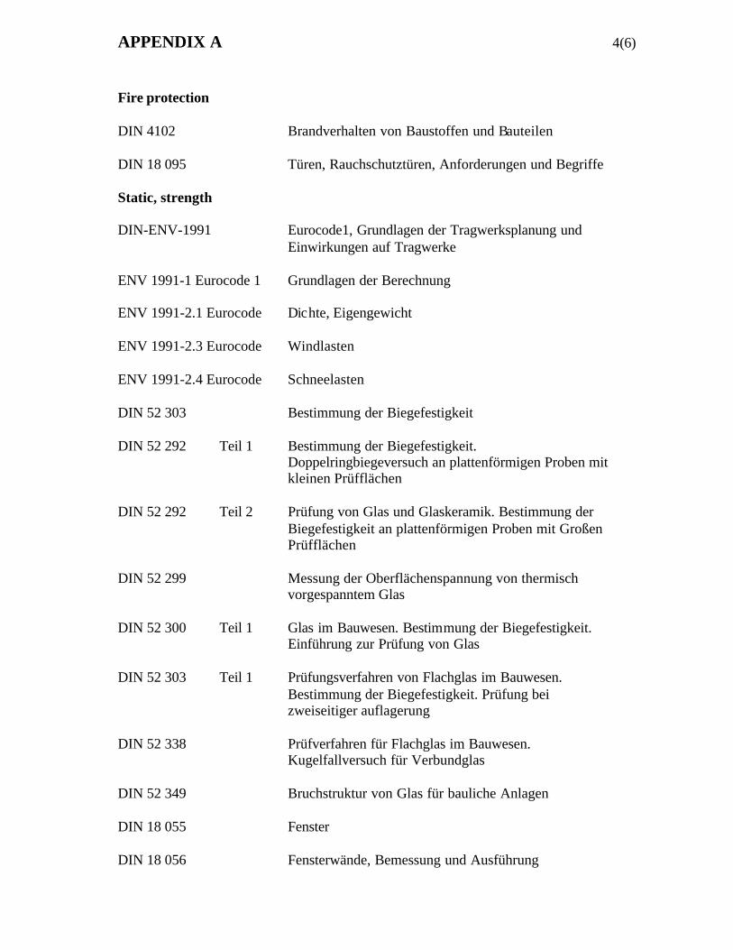
APPENDIX A 4(6)
Fire protection
DIN 4102 Brandverhalten von Baustoffen und Bauteilen
DIN 18 095 Türen, Rauchschutztüren, Anforderungen und Begriffe
Static, strength
DIN-ENV-1991 Eurocode1, Grundlagen der Tragwerksplanung undEinwirkungen auf Tragwerke
ENV 1991-1 Eurocode 1 Grundlagen der Berechnung
ENV 1991-2.1 Eurocode Dichte, Eigengewicht
ENV 1991-2.3 Eurocode Windlasten
ENV 1991-2.4 Eurocode Schneelasten
DIN 52 303 Bestimmung der Biegefestigkeit
DIN 52 292 Teil 1 Bestimmung der Biegefestigkeit.Doppelringbiegeversuch an plattenförmigen Proben mitkleinen Prüfflächen
DIN 52 292 Teil 2 Prüfung von Glas und Glaskeramik. Bestimmung derBiegefestigkeit an plattenförmigen Proben mit GroßenPrüfflächen
DIN 52 299 Messung der Oberflächenspannung von thermischvorgespanntem Glas
DIN 52 300 Teil 1 Glas im Bauwesen. Bestimmung der Biegefestigkeit.Einführung zur Prüfung von Glas
DIN 52 303 Teil 1 Prüfungsverfahren von Flachglas im Bauwesen.Bestimmung der Biegefestigkeit. Prüfung beizweiseitiger auflagerung
DIN 52 338 Prüfverfahren für Flachglas im Bauwesen.Kugelfallversuch für Verbundglas
DIN 52 349 Bruchstruktur von Glas für bauliche Anlagen
DIN 18 055 Fenster
DIN 18 056 Fensterwände, Bemessung und Ausführung
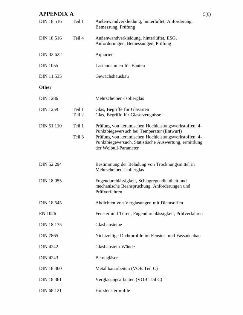
APPENDIX A 5(6)
DIN 18 516 Teil 1 Außenwandverkleidung, hinterlüftet, Anforderung,Bemessung, Prüfung
DIN 18 516 Teil 4 Außenwandverkleidung, hinterlüftet, ESG,Anforderungen, Bemessungen, Prüfung
DIN 32 622 Aquarien
DIN 1055 Lastannahmen für Bauten
DIN 11 535 Gewächshausbau
Other
DIN 1286 Mehrscheiben-Isolierglas
DIN 1259 Teil 1 Glas, Begriffe für GlasartenTeil 2 Glas, Begriffe für Glaserzeugnisse
DIN 51 110 Teil 1 Prüfung von keramischen Hochleistungswerkstoffen. 4-Punktbiegeversuch bei Temperatur (Entwurf)
Teil 3 Prüfung von keramischen Hochleistungswerkstoffen. 4-Punktbiegeversuch, Statistische Auswertung, ermittlungder Weibull-Parameter
DIN 52 294 Bestimmung der Beladung von Trocknungsmittel inMehrscheiben-Isolierglas
DIN 18 055 Fugendurchlässigkeit, Schlagregendichtheit undmechanische Beanspruchung, Anforderungen undPrüfverfahren
DIN 18 545 Abdichten von Verglasungen mit Dichtsoffen
EN 1026 Fenster und Türen, Fugendurchlässigkeit, Prüfverfahren
DIN 18 175 Glasbausteine
DIN 7865 Nichtzellige Dichtprofile im Fenster- und Fassadenbau
DIN 4242 Glasbaustein-Wände
DIN 4243 Betongläser
DIN 18 360 Metallbauarbeiten (VOB Teil C)
DIN 18 361 Verglasungsarbeiten (VOB Teil C)
DIN 68 121 Holzfensterprofile
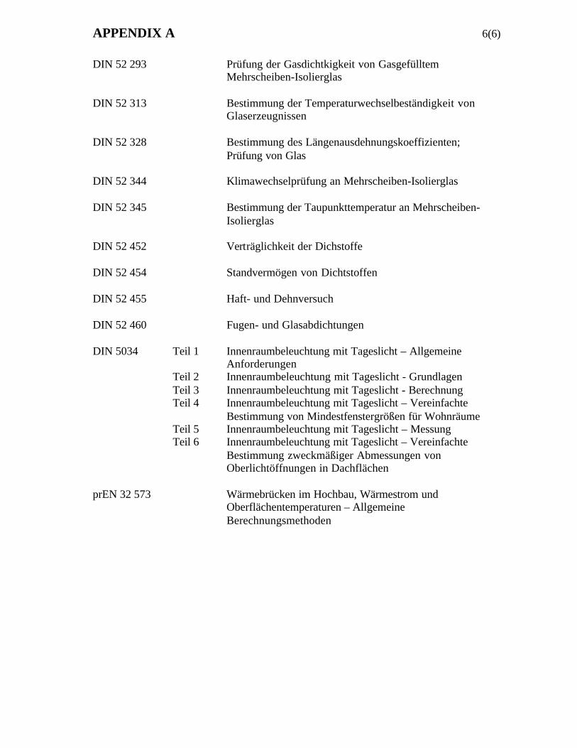
APPENDIX A 6(6)
DIN 52 293 Prüfung der Gasdichtkigkeit von GasgefülltemMehrscheiben-Isolierglas
DIN 52 313 Bestimmung der Temperaturwechselbeständigkeit vonGlaserzeugnissen
DIN 52 328 Bestimmung des Längenausdehnungskoeffizienten;Prüfung von Glas
DIN 52 344 Klimawechselprüfung an Mehrscheiben-Isolierglas
DIN 52 345 Bestimmung der Taupunkttemperatur an Mehrscheiben-Isolierglas
DIN 52 452 Verträglichkeit der Dichstoffe
DIN 52 454 Standvermögen von Dichtstoffen
DIN 52 455 Haft- und Dehnversuch
DIN 52 460 Fugen- und Glasabdichtungen
DIN 5034 Teil 1 Innenraumbeleuchtung mit Tageslicht – AllgemeineAnforderungen
Teil 2 Innenraumbeleuchtung mit Tageslicht - GrundlagenTeil 3 Innenraumbeleuchtung mit Tageslicht - BerechnungTeil 4 Innenraumbeleuchtung mit Tageslicht – Vereinfachte
Bestimmung von Mindestfenstergrößen für WohnräumeTeil 5 Innenraumbeleuchtung mit Tageslicht – MessungTeil 6 Innenraumbeleuchtung mit Tageslicht – Vereinfachte
Bestimmung zweckmäßiger Abmessungen vonOberlichtöffnungen in Dachflächen
prEN 32 573 Wärmebrücken im Hochbau, Wärmestrom undOberflächentemperaturen – AllgemeineBerechnungsmethoden
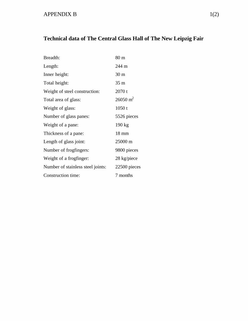
APPENDIX B 1(2)
Technical data of The Central Glass Hall of The New Leipzig Fair
Breadth: 80 m
Length: 244 m
Inner height: 30 m
Total height: 35 m
Weight of steel construction: 2070 t
Total area of glass: 26050 m2
Weight of glass: 1050 t
Number of glass panes: 5526 pieces
Weight of a pane: 190 kg
Thickness of a pane: 18 mm
Length of glass joint: 25000 m
Number of frogfingers: 9800 pieces
Weight of a frogfinger: 28 kg/piece
Number of stainless steel joints: 22500 pieces
Construction time: 7 months
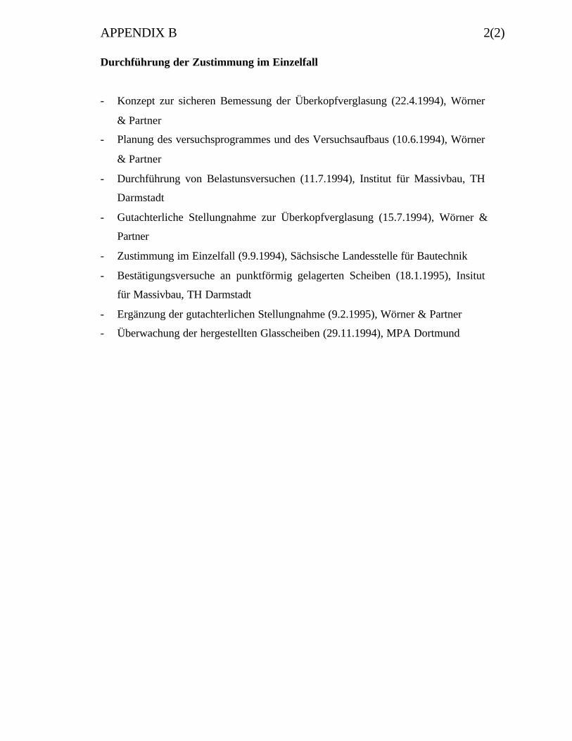
APPENDIX B 2(2)
Durchführung der Zustimmung im Einzelfall
- Konzept zur sicheren Bemessung der Überkopfverglasung (22.4.1994), Wörner
& Partner
- Planung des versuchsprogrammes und des Versuchsaufbaus (10.6.1994), Wörner
& Partner
- Durchführung von Belastunsversuchen (11.7.1994), Institut für Massivbau, TH
Darmstadt
- Gutachterliche Stellungnahme zur Überkopfverglasung (15.7.1994), Wörner &
Partner
- Zustimmung im Einzelfall (9.9.1994), Sächsische Landesstelle für Bautechnik
- Bestätigungsversuche an punktförmig gelagerten Scheiben (18.1.1995), Insitut
für Massivbau, TH Darmstadt
- Ergänzung der gutachterlichen Stellungnahme (9.2.1995), Wörner & Partner
- Überwachung der hergestellten Glasscheiben (29.11.1994), MPA Dortmund