calor2000 conference annecy,france oct 2000 1 leslie groer columbia universitydØ calorimeter...
TRANSCRIPT

DD
CALOR2000 ConferenceAnnecy,France Oct 20001
Leslie GroerColumbia University DØ Calorimeter Electronics Upgrade
Columbia University New York
DØ Calorimeter Electronics Upgrade for Tevatron Run II
Leslie Groer
October 11, 2000
CALOR2000IX International Conference on Calorimetry in Particle Physics
Annecy, France October 9-14, 2000
DD
CALOR2000 ConferenceAnnecy,France Oct 20002
Leslie GroerColumbia University DØ Calorimeter Electronics Upgrade
2
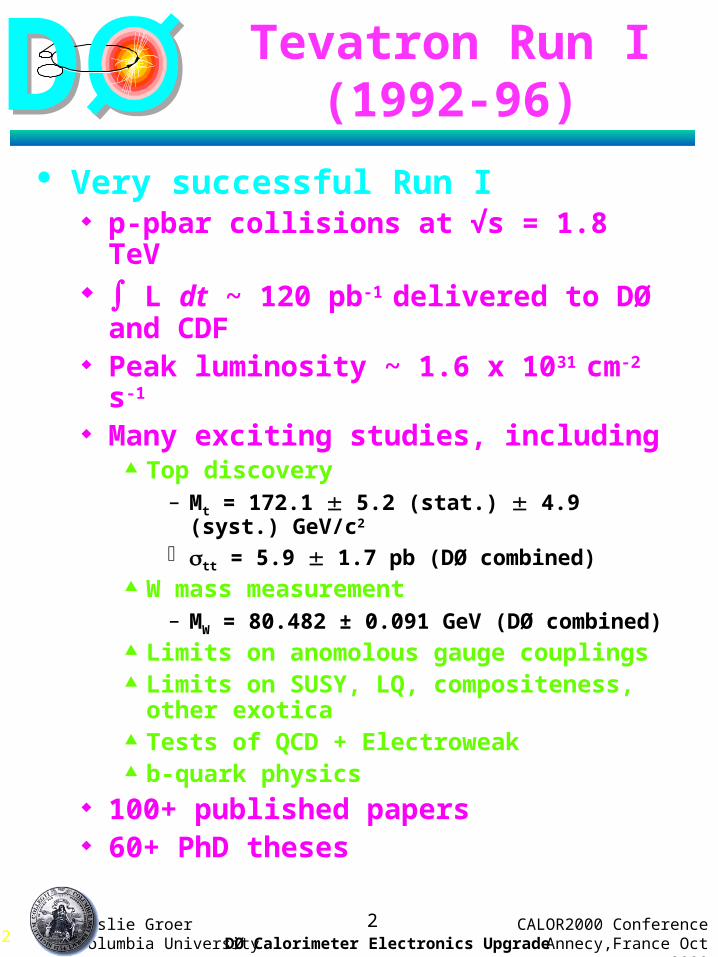
Tevatron Run I (1992-96)
Very successful Run I p-pbar collisions at √s = 1.8 TeV L dt ~ 120 pb-1 delivered to DØ
and CDF Peak luminosity ~ 1.6 x 1031 cm-2 s-1
Many exciting studies, including Top discovery
– Mt = 172.1 5.2 (stat.) 4.9 (syst.) GeV/c2
tt = 5.9 1.7 pb (DØ combined) W mass measurement
– MW = 80.482 ± 0.091 GeV (DØ combined) Limits on anomolous gauge couplings Limits on SUSY, LQ, compositeness,
other exotica Tests of QCD + Electroweak b-quark physics
100+ published papers 60+ PhD theses
DD
CALOR2000 ConferenceAnnecy,France Oct 20003
Leslie GroerColumbia University DØ Calorimeter Electronics Upgrade
3
Fermilab Accelerator Upgrade
Two new machines at FNAL for Run II: Main Injector
150 GeV conventional proton accelerator
Supports luminosity upgrade for the collider, future 120 GeV fixed-target program, and neutrino production for NUMI
Recycler 8 GeV permanent magnet
(monoenergetic) storage ring permits antiproton recycling from the
collider Tevatron Status and Schedule
DØ and CDF roll in – January 2001 Run II start – March 2001 1.8 Tev 2 TeV Goal: L dt = 2 fb-1 by 2003 15 fb-1+ by 2006? Very first p-pbar collisions seen
(August 2000)

DD
CALOR2000 ConferenceAnnecy,France Oct 20004
Leslie GroerColumbia University DØ Calorimeter Electronics Upgrade
4
Run II Parameters
Parameter Run IB (1993-1995)
Run II MI plus Recycler
Units
Energy 900 1000 GeV
Protons/bunch 23 x 1010 27 x 1010
P-bars / bunch 5.5 x 10¹⁰ 7.5 x 10¹⁰
Bunches 6 36x36 140x103
P-bar stacking 6 x 10¹⁰ 20 x 1010 per hour
Crossing angle 0 136 µrad
Luminosity 1.6 x 1031 2.1 x 1032 cm-2 s-1
Bunch Spacing 3500 396 132 nsec
Interactions per crossing
2.7 4.8
0%
10%
20%
30%
40%
0 1 2 3 4 5 6 7 8 9
396 ns132 ns
Run II Bunch Spacing
# of Ints. / Crossing
% C
ross
ing
s

DD
CALOR2000 ConferenceAnnecy,France Oct 20005
Leslie GroerColumbia University DØ Calorimeter Electronics Upgrade
Run IIDØ Upgrade
New
Sole
noid
, Tra
ckin
g S
yste
m
SM
T,
SciF
i, P
resh
ow
ers
Sh
ield
ing
Forw
ard
Min
i-D
rift
Tu
bes
Forw
ard
Scin
tillato
r(m
uon
tri
gg
er)
Cen
tral S
cin
tillato
r(m
uon
tri
gg
er)
+ N
ew
Ele
ctr
on
ics,
Tri
g,
DA
Q
Pseu
dora
pid
ity
=
—ln
tan
(/
2)

DD
CALOR2000 ConferenceAnnecy,France Oct 20006
Leslie GroerColumbia University DØ Calorimeter Electronics Upgrade
6
Inner Detectors
ForwardPreshower
Silicon Microstrip Tracker Fiber Tracker
Solenoid
Central Preshower
1.4 m
Intercryostat Detector
• Superconducting solenoid (2T)• 840k channel silicon vertex detector• 77k channel scintillating fiber tracker • Scintillating strip preshower in central and
forward regions. (6k and 16k channels)• Intercryostat detector (scintillator tiles)

DD
CALOR2000 ConferenceAnnecy,France Oct 20007
Leslie GroerColumbia University DØ Calorimeter Electronics Upgrade
7
Preshower Detectors
Central mounted on solenoid (|| < 1.2) Forward on calorimeter endcaps (1.4 < || < 2.5) Extruded triangular scintillator strips with
embedded WLS fibers and Pb absorber Trigger on low-pT EM showers Reduce overall electron trigger rate by x3-5 VLPC and SVX II readout
Title: D:\ANATOLY\HOWARD\UP-71-20.EPS Creator: AutoCAD PSOUTCreationDate: 1997-03-06

DD
CALOR2000 ConferenceAnnecy,France Oct 20008
Leslie GroerColumbia University DØ Calorimeter Electronics Upgrade
8
Intercryostat Detector (ICD)
FPS
ICD
Design Scintillator based with phototube readout
similar to Run I design. Re-use existing PMT’s (Hamamatsu R647).
16 supertile modules per cryostat with a total of 384 scintillator tiles
WLS fiber readout of scintillator tiles Clear fiber light piping to region of low field
~40-50% signal loss over 5-6m fiber. Readout/calibration scheme for electronics
same as for L. Ar. Calorimeter but with adapted electronics and pulser shapes
LED pulsers used for PMT calibration Relative yields measured > 20 p.e./m.i.p.
Objectives Maintain performance in
presence of a magnetic field and additional material from solenoid
Improve coverage for the region 1.1 < || < 1.4
Improves jet ET and ET/
LaTechUT, Arlington
DD
CALOR2000 ConferenceAnnecy,France Oct 20009
Leslie GroerColumbia University DØ Calorimeter Electronics Upgrade
9
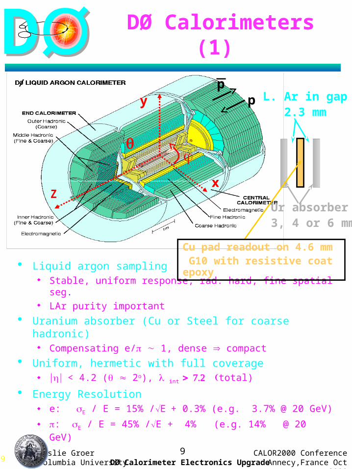
DØ Calorimeters (1)
Z
y
x
p
Liquid argon sampling Stable, uniform response, rad. hard, fine spatial seg. LAr purity important
Uranium absorber (Cu or Steel for coarse hadronic) Compensating e/ 1, dense compact
Uniform, hermetic with full coverage < 4.2 ( 2o), int total)
Energy Resolution e: E / E = 15% /E+ 0.3% (e.g. 3.7% @ 20 GeV)
: E / E = 45% /E + 4% (e.g. 14% @ 20 GeV)
p_
L. Ar in gap 2.3 mm
Ur absorber3, 4 or 6 mm
Cu pad readout on 4.6 mm G10 with resistive coat epoxy

DD
CALOR2000 ConferenceAnnecy,France Oct 200010
Leslie GroerColumbia University DØ Calorimeter Electronics Upgrade
10
DØ Calorimeters (2)
IntercryostatDetector (ICD)
Arranged in semi-projective towers Readout cells ganged in layers Readout segmented into for charge detection
Transverse segmentation x x At shower max. (EM3) x x
+2.5 kV (E = 11 kV/cm) gives drift time ~ 450 ns
Layer CC EC
EM1,2,3,4 XO : 2,2,7,10
3mm Ur
XO : (0.3),3,8,9
(1.4mm Fe) 4mm Ur
FH1,2,3,(4) O : 1.3,1.0,0.9
6mm Ur
O : 1.3,1.2,1.2,1.2
6mm Ur
CH1,(2,3) O : 3.0
46.5mm Cu
O : 3.0, (3.0, 3.0)
46.5mm Fe
EM
FH
CH OH
MH
IHEM
Massless Gap (no absorber)

DD
CALOR2000 ConferenceAnnecy,France Oct 200011
Leslie GroerColumbia University DØ Calorimeter Electronics Upgrade
11
Timing
3.56us
4.36us 2.64us
superbunch gap
396ns
gap used to form triggerand sample baselines
this gap is too small toform trigger and samplebaseline
Bunch structure
Run I 6x6
Run II 36x36
Design all the electronics, triggers and DAQ to handle bunch structure with a minimum of 132ns between bunches and higher luminosity
Maintain detector performance

DD
CALOR2000 ConferenceAnnecy,France Oct 200012
Leslie GroerColumbia University DØ Calorimeter Electronics Upgrade
12
Calorimeter Readout Electronics
Objectives Accommodate reduced minimum bunch spacing
from 3.5 s to 396 ns or 132 ns and L~ 2 x 1032 cm-2
s-1
Storage of analog signal for 4 s for L1 trigger formation
Generate trigger signals for calorimeter L1 trigger Maintain present level of noise performance and
pile-up performance
Methods
Replace preamplifiers Replace shapers Add analog storage Replace calibration system Replace timing and control system Keep Run I ADCs, crates and most cabling to
minimize cost and time
LAr det. preampshaper +
BLS ADCanalog buffer storage
L1+L2 trigger

DD
CALOR2000 ConferenceAnnecy,France Oct 200013
Leslie GroerColumbia University DØ Calorimeter Electronics Upgrade
13
Calorimeter Electronics Upgrade
55K readout channels Replace signal cables from cryostat to preamps
(110 30 for impedance match) Replacement of preamps, shapers, baseline
subtraction circuitry (BLS)
Addition of analog storage (48-element deep Switched Capacitor Array (SCA))
New Timing and Control New calibration pulser + current cables
Preamp/Driver
Trig. sum
Filter/Shaper
x1
x8
SCA (48 deep)
SCA (48 deep)
SCA (48 deep)
SCA (48 deep)
BLSOutputBufferDetc
.
Bank 0
Bank 1
Replace cablesfor impedencematch
new low noise preamp & driver
Shorter shaping~400ns
SCA analog storage>4sec, alternate
Additionalbuffering for L2 & L3
SCA
new calibratedpulse injection
BLS Card

DD
CALOR2000 ConferenceAnnecy,France Oct 200014
Leslie GroerColumbia University DØ Calorimeter Electronics Upgrade
14
Preamplifier
2”
FET
driverpreamp
similar to Run 1 version except • Dual FET frontend• Compensation for detector capacitance• Faster recovery time
New output driverfor terminatedsignal transmission
out
in
Preamplifier
New calorimeter preamp
Hybrid on ceramic
48 preamps on a motherboard
New low-noise switching power supplies in steel box

DD
CALOR2000 ConferenceAnnecy,France Oct 200015
Leslie GroerColumbia University DØ Calorimeter Electronics Upgrade
15
Preamp Species
14+1 (ICD) species of preamp Feedback provide compensation for RC from
detector capacitance and cable impedance Readout in towers of up to 12 layers
0:EM1, 1:EM2, 2-5:EM3, 6:EM4, 7-10:FH, 11:CH
4 towers per preamp motherboard provides trigger tower (EM+ HAD) of x 0.2 x 0.2
Preamp species
Avg. Detector cap. (nF)
Layer readout
Feedback cap (pF)
RC
(ns)
Total preamps
A 0.26-0.56 EM1,2, HAD
5 0 13376
B 1.1-1.5 HAD 5 26 2240
C 1.8-2.6 HAD 5 53 11008
D 3.4-4.6 HAD 5 109 8912
E 0.36-0.44 CC EM3 10 0 9920
F 0.72-1.04 EC EM3,4 10 14 7712
G 1.3-1.7 CC EM4, EC EM3,4
10 32 3232
Ha-Hg 2- 4 EC EM3,4 10 47-110 896
I — ICD 22 0 384
55680

DD
CALOR2000 ConferenceAnnecy,France Oct 200016
Leslie GroerColumbia University DØ Calorimeter Electronics Upgrade
16
L1 SCAs (2+2) L2 SCA
Array of 48 capacitors topipeline calorimeter signals
BLS Card
BLS motherboard v2.2 BLS daughterboard
Shapers (12)
Use 2 L1 SCA chips for each x1/x8 gain - alternate read/write for each superbunch
Readout time ~ 6 s (< length SCA buffer) L2 SCA buffers readout for transfer to ADC after L2
trigger decision No dead time for 10KHz L1 trigger rate Trigger tower formation (0.2 x 0.2) for L1 Rework existing power supplies New T&C signals to handle SCA requirements and
interface to L1/L2 trigger system( use FPGAs and FIFOs)
Outputcircuit
Trigger pickoff/summers
~ 1 inch
shaper

DD
CALOR2000 ConferenceAnnecy,France Oct 200017
Leslie GroerColumbia University DØ Calorimeter Electronics Upgrade
17
SCA
Designed by LBL, FNAL, SUNY Stony Brook (25k in system)
Not designed for simultaneous read and write operations
two SCA banks alternate reading and writing
12 bit dynamic range (1/4000) low and high gain path for
each readout channel (X8/X1) maintain 15 bit dynamic range
cap ref
input
write address decoder/control
read address decoder/control
..x48..
ref
reset
out
1”
12 channels
48deep
packaged
DD
CALOR2000 ConferenceAnnecy,France Oct 200018
Leslie GroerColumbia University DØ Calorimeter Electronics Upgrade
18
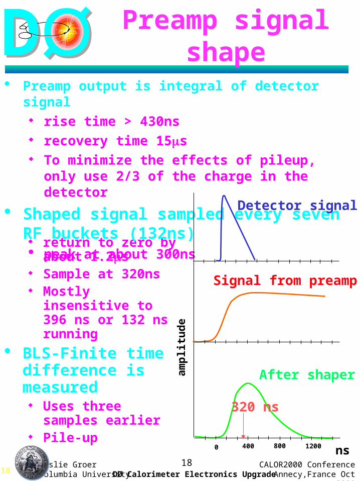
Preamp signal shape
return to zero by about 1.2s
Sample at 320ns Mostly insensitive to
396 ns or 132 ns running
BLS-Finite time difference is measured Uses three samples
earlier Pile-up
Preamp output is integral of detector signal rise time > 430ns recovery time 15s To minimize the effects of pileup, only use 2/3
of the charge in the detector
Shaped signal sampled every seven RF buckets (132ns) peak at about 300ns
After shaper
Signal from preamp
0 400 1200800 ns
amp
litu
de
320 ns
Detector signal

DD
CALOR2000 ConferenceAnnecy,France Oct 200019
Leslie GroerColumbia University DØ Calorimeter Electronics Upgrade
19
Noise Contributions
Design for 400ns shaping lower noise – 2 FET input luminosity of 2x1032 cm–2 s-1
Re-optimized three contributions Electronics noise: x 1.6
shaping time (2s 400ns) (~ t) lower noise preamp (2 FET) (~ 1/ 2)
Uranium noise: x 2.3 shorter shaping time (~ t)
Pile-up noise: x 1.3 luminosity (~ L) shorter shaping times (~ t)
Comparable noise performance at 1032 with new electronics as with old electronics at 1031
Simulations of the W mass “bench-mark” confirm that pile-up will not limit our W mass at Run II.

DD
CALOR2000 ConferenceAnnecy,France Oct 200020
Leslie GroerColumbia University DØ Calorimeter Electronics Upgrade
20
Cell Capacitance
Electronic noise Total
3.5 MeV
U noise
Estimates of Noise Contributions
EM3 layer per cell
nF
GeV
GeV
GeV

DD
CALOR2000 ConferenceAnnecy,France Oct 200021
Leslie GroerColumbia University DØ Calorimeter Electronics Upgrade
21
Electronics Calibration
Goals Calibrate electronics to better than 1%
Measure pedestals due to electronics and Ur noise
Determine zero suppression limits Determine gains (x1,x8) from pulsed channels Study channel-to-channel response; linearity
Commissioning Bad channels Trigger verification Check channel mapping Monitoring tool
Oracle Database for storage Database used to download pedestals
and zero-suppression limits to ADC boards

DD
CALOR2000 ConferenceAnnecy,France Oct 200022
Leslie GroerColumbia University DØ Calorimeter Electronics Upgrade
22
Preamp Box
2 Fanouts(2x3x16 switches)
switch
Electronics Calibration System
Pulser
Trigger
Power Supply
PIB
6 commands (3x2)96 currents
Pulser Interface Board:• VME interface • automated calibration procedure
Active Fanout with Switches: pulse shaping and distribution• Open switch when receive command signal
Pulser: DC current and command generator:• DC current set by 18-bit DAC• 96 enable registers• 6-programmable 8-bit delays for command signals with 2ns step size
LPNHE-ParisLAL-Orsay

DD
CALOR2000 ConferenceAnnecy,France Oct 200023
Leslie GroerColumbia University DØ Calorimeter Electronics Upgrade
23
Calibration Pulser Response
Linear response for DAC pulse height (0-65k)
Fully saturate ADC
(at DAC= 90k)
Linearity of calibration and calorimeter electronics better than 0.2% (for DAC < 65k)
Cross-talk in neighboring channels < 1.5% Uniformity of pulser modules better than 1% No significant noise added from the calibration
system Correction factors need to be determined
mean
Deviation from linearity
Single channel (ADC vs. DAC)
better than 0.2%
DD
CALOR2000 ConferenceAnnecy,France Oct 200024
Leslie GroerColumbia University DØ Calorimeter Electronics Upgrade
24
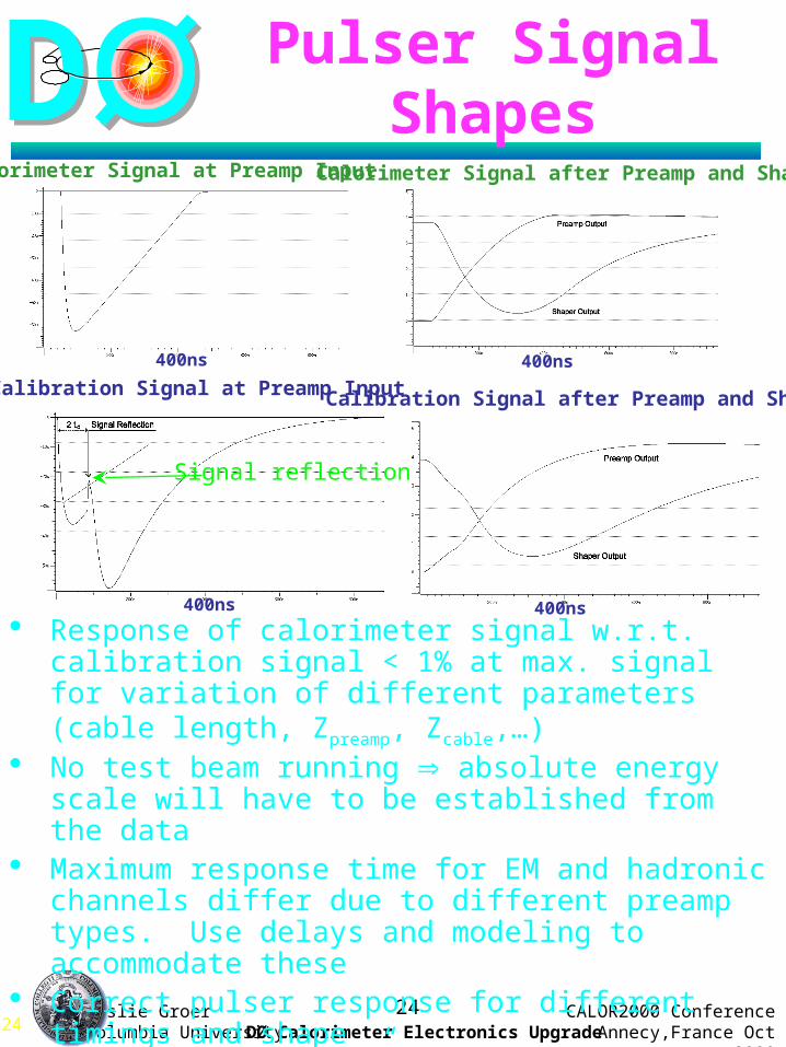
Pulser Signal Shapes
Calorimeter Signal at Preamp Input
Calibration Signal at Preamp Input
Calorimeter Signal after Preamp and Shaper
Calibration Signal after Preamp and Shaper
400ns
400ns400ns
400ns Response of calorimeter signal w.r.t. calibration signal <
1% at max. signal for variation of different parameters (cable length, Zpreamp, Zcable,…)
No test beam running absolute energy scale will have to be established from the data
Maximum response time for EM and hadronic channels differ due to different preamp types. Use delays and modeling to accommodate these
Correct pulser response for different timings and shape Use initial “guess” based on Monte-Carlo sampling
weights and Spice models of the electronics.
Signal reflection

DD
CALOR2000 ConferenceAnnecy,France Oct 200025
Leslie GroerColumbia University DØ Calorimeter Electronics Upgrade
25
EM Scale Z ee (100k) sets the absolute EM scale Check with
0, J/ or (1S) ee
Use W e sample (1.6M) to check symmetry in
Jet Energy Scale + jet data possibly also Z + jet, (Z ee/)
very low backgrounds and harder Et spectrum but low statistics
We have E/p this time!
Determining EM/Jet Energy Scale
Z ee
J/ ee ee

DD
CALOR2000 ConferenceAnnecy,France Oct 200026
Leslie GroerColumbia University DØ Calorimeter Electronics Upgrade
26
Effect of added material
New solenoid and preshower detectors increased the radiation length Degrades both energy
response and resolution
Introduces non-uniformity in response
50 GeV electron
X0
central forward

DD
CALOR2000 ConferenceAnnecy,France Oct 200027
Leslie GroerColumbia University DØ Calorimeter Electronics Upgrade
27
Optimization of Calorimeter Response
Minimize (Etrue - aiEi)2
ai = layer weighting
Ei = layer Energy
Utilizing these energy correlations improves energy uniformity and resolution by ~10%
50 GeV 50 GeV e
E/E

DD
CALOR2000 ConferenceAnnecy,France Oct 200028
Leslie GroerColumbia University DØ Calorimeter Electronics Upgrade
28
Liquid Argon Monitoring
Each cryostat has four cells 241Am sources – 5 MeV , 0.1Ci
gives about 4 fC in Lar gap with 500Hz trigger rate
Check LAr response (constant to < 0.5% in Run I)
106Ru (< 3.5 MeV , 1yr half-life) one stronger source (~10-10 Ci) should give
about 0.3Hz triggers (about 2 fC) Check LAr purity (< 1% in Run I)
Mainz group design (based on ATLAS) Separate HV, preamplifier and trigger system Preamplifier and differential driver give gain
of about 50 gives signals of about 0.1V Shaping and ADC on receiver boards
(FPGA) On board collection and storage of
histogram information Extract data over CAN-bus

DD
CALOR2000 ConferenceAnnecy,France Oct 200029
Leslie GroerColumbia University DØ Calorimeter Electronics Upgrade
29
Conclusions
Dzero is upgrading its detector L.Argon calorimeter untouched
Harder machine conditions and new environment (solenoid)
– New Calorimeter Electronics– Improved ICD– New Central and Forward Preshower
Similar performance with 20x more data
Run II start in 6 months
watch this space!!!