call traffic monitoring guide - oracle · packet trace for both call legs 1-42 packet trace ......
TRANSCRIPT

Oracle® Communications SessionBorder ControllerCall Traffic Monitoring Guide
Release S-CZ7.3.0January 2018

Oracle Communications Session Border Controller Call Traffic Monitoring Guide, Release S-CZ7.3.0
Copyright © 2014, 2018, Oracle and/or its affiliates. All rights reserved.
This software and related documentation are provided under a license agreement containing restrictions on use anddisclosure and are protected by intellectual property laws. Except as expressly permitted in your license agreement orallowed by law, you may not use, copy, reproduce, translate, broadcast, modify, license, transmit, distribute, exhibit,perform, publish, or display any part, in any form, or by any means. Reverse engineering, disassembly, or decompilationof this software, unless required by law for interoperability, is prohibited.
The information contained herein is subject to change without notice and is not warranted to be error-free. If you findany errors, please report them to us in writing.
If this is software or related documentation that is delivered to the U.S. Government or anyone licensing it on behalf ofthe U.S. Government, then the following notice is applicable:
U.S. GOVERNMENT END USERS: Oracle programs, including any operating system, integrated software, anyprograms installed on the hardware, and/or documentation, delivered to U.S. Government end users are "commercialcomputer software" pursuant to the applicable Federal Acquisition Regulation and agency-specific supplementalregulations. As such, use, duplication, disclosure, modification, and adaptation of the programs, including any operatingsystem, integrated software, any programs installed on the hardware, and/or documentation, shall be subject to licenseterms and license restrictions applicable to the programs. No other rights are granted to the U.S. Government.
This software or hardware is developed for general use in a variety of information management applications. It is notdeveloped or intended for use in any inherently dangerous applications, including applications that may create a risk ofpersonal injury. If you use this software or hardware in dangerous applications, then you shall be responsible to take allappropriate fail-safe, backup, redundancy, and other measures to ensure its safe use. Oracle Corporation and its affiliatesdisclaim any liability for any damages caused by use of this software or hardware in dangerous applications.
Oracle and Java are registered trademarks of Oracle and/or its affiliates. Other names may be trademarks of theirrespective owners.
Intel and Intel Xeon are trademarks or registered trademarks of Intel Corporation. All SPARC trademarks are used underlicense and are trademarks or registered trademarks of SPARC International, Inc. AMD, Opteron, the AMD logo, andthe AMD Opteron logo are trademarks or registered trademarks of Advanced Micro Devices. UNIX is a registeredtrademark of The Open Group.
This software or hardware and documentation may provide access to or information about content, products, andservices from third parties. Oracle Corporation and its affiliates are not responsible for and expressly disclaim allwarranties of any kind with respect to third-party content, products, and services unless otherwise set forth in anapplicable agreement between you and Oracle. Oracle Corporation and its affiliates will not be responsible for any loss,costs, or damages incurred due to your access to or use of third-party content, products, or services, except as set forth inan applicable agreement between you and Oracle.

Contents
Preface: About this Guide
1 Call Traffic Monitoring
SelectiveCall Recording SIPREC 1-1SIPREC Feature 1-1Configuring SIPREC 1-2
Session Recording Server (SRS) 1-2Session Recording Group 1-3
Load Balancing 1-3Session Recording Group within Logical Remote Entities 1-4
Selective Recording 1-4High Availability (HA) Support 1-5SIPREC Configuration Procedure 1-5
Session-recording-server Attribute 1-5Session-recording-group Attribute (for HA only) 1-7Realm-config Attribute 1-9Session-agent Attribute 1-10Sip-interface Attribute 1-11
P-Asserted Identity and Diversion Headers in SIPREC Metadata 1-12Metadata Contents 1-13Show Commands for Recording Sessions 1-14
Show rec 1-14Show rec redundancy 1-15
Inserting SIP Headers into SIPREC Metadata 1-16Sample Metadata 1-16Configure SIP Headers for SIPREC Metadata 1-18
SIPREC Recording Session Refresh 1-18Timer_B 1-19OPTIONS Request/Response 1-19Recording Session Refresh Configuration 1-19
Codec Negotiation 1-20SIPREC Call Flows 1-20
iii

Selective Recording 1-21Normal Call (recording required) 1-21Sample SDP and Metadata 1-22Normal Call (recording not required) 1-23Early Media Call (recording not required) 1-24REFER Pass-Through Call (REFER handled by User Agent) 1-26REFER Call (REFER handled by Oracle Communications Session BorderController) 1-27SRS Indicates Busy in Call (recording not required) 1-29Call Transfer Scenario (recording required) 1-31
Oracle Communications Session Monitor Mediation Engine 1-32IPFIX 1-33Communications Monitor Configuration 1-33
Communication Monitor 1-33TSCF Rekey Profile Configuration 1-35TLS Profile Configuration 1-36
Oracle Communications Session Monitor Statistics 1-37Packet Trace 1-39
Packet Trace Remote 1-39Packet Trace Local 1-40Packet Trace Scenarios 1-41
Packet Trace for One Endpoint 1-41Packet Trace for Both Call Legs 1-42Packet Trace for a Oracle Communications Session Border Controller SignalingAddress 1-42
Running Packet Trace 1-43Configuring a Trace Server 1-44Starting a Remote Packet Trace 1-44Stopping a Remote Packet Trace 1-45Starting a Local Packet Trace 1-45Stopping a Local Packet Trace 1-46
2 Web-based GUI
Introduction 2-1Web Browser Support 2-1Overview 2-1
Logging in 2-1About Information 2-3Customizing the Page Display 2-4
Changing Number of Data Items on the Page 2-5Navigating Pages 2-6
iv

Refresh 2-6Pop-up Context Menu 2-7Help Menu 2-7
Tool-Tip Help 2-9Search for a Record 2-9Exporting Information to a Text File 2-14
Session Reports 2-15Session Report Configuration 2-17Ladder Diagram 2-17
Session Summary 2-19SIP Message Details 2-20QoS Statistics 2-21
Registration Reports 2-22Subscription Reports 2-24Notable Event Reports 2-26
v

Preface: About this Guide
The Oracle Communications Session Border Controller Call Traffic Monitoring Guide providesinformation about monitoring the call traffic on your system.
Related Documentation
The following table lists the members that comprise the documentation set for this release.
Document Name Document Description
Acme Packet 4500 Hardware InstallationGuide
Contains information about the components andinstallation of the Acme Packet 4500.
Acme Packet 3820 Hardware InstallationGuide
Contains information about the components andinstallation of the Acme Packet 3820.
Acme Packet 4600 Hardware InstallationGuide
Contains information about the components andinstallation of the Acme Packet 4600.
Acme Packet 6100 Hardware InstallationGuide
Contains information about the components andinstallation of the Acme Packet 6100.
Acme Packet 6300 Hardware InstallationGuide
Contains information about the components andinstallation of the Acme Packet 6300.
Release Notes Contains information about the current documentation setrelease, including new features and management changes.
ACLI Configuration Guide Contains information about the administration andsoftware configuration of the Service Provider OracleCommunications Session Border Controller.
ACLI Reference Guide Contains explanations of how to use the ACLI, as analphabetical listings and descriptions of all ACLIcommands and configuration parameters.
Maintenance and Troubleshooting Guide Contains information about Oracle CommunicationsSession Border Controller logs, performanceannouncements, system management, inventorymanagement, upgrades, working with configurations, andmanaging backups and archives.
MIB Reference Guide Contains information about Management Information Base(MIBs), Oracle Communication's enterprise MIBs, generaltrap information, including specific details about standardtraps and enterprise traps, Simple Network ManagementProtocol (SNMP) GET query information (includingstandard and enterprise SNMP GET query names, objectidentifier names and numbers, and descriptions), examplesof scalar and table objects.
Accounting Guide Contains information about the Oracle CommunicationsSession Border Controller’s accounting support, includingdetails about RADIUS and Diameter accounting.
HDR Resource Guide Contains information about the Oracle CommunicationsSession Border Controller’s Historical Data Recording(HDR) feature. This guide includes HDR configurationand system-wide statistical information.
Preface: About this Guide
vi
Document Name Document Description
Administrative Security Essentials Contains information about the Oracle CommunicationsSession Border Controller’s support for its AdministrativeSecurity license.
Security Guide Contains information about security considerations andbest practices from a network and application securityperspective for the Oracle Communications SessionBorder Controller family of products.
Installation and Platform Preparation Guide Contains information about upgrading system images andany pre-boot system provisioning.
Call Traffic Monitoring Guide Contains information about traffic monitoring and packettraces as collected on the system. This guide also includesWebGUI configuration used for the SIP Monitor and Traceapplication.
Revision History
Date Description
October 2015 • Initial Release• Remove MGCP support in documentation
May 2016 • Adds requirement that any media interfaceconfigured with comm-monitor must alsobelong to a realm.
September 2016 • Removes Single SRS capacity sectionFebruary 2017 • Updates Egress RTP packet capture
information under Packet TraceApril 2017 • Clarifies that local packet capture does not
include RTPJanuary 2018 • Removes deprecated Web Server
Configuration chapter.
Preface: About this Guide
vii
1Call Traffic Monitoring
SelectiveCall Recording SIPRECThe SIPREC protocol is the protocol used to interact between a Session Recording Client(SRC) (the role performed by Oracle Communications Session Border Controller) and aSession Recording Server (SRS) (a 3rd party call recorder or Oracle CommunicationsInteractive Session Recorder’s Record and Store Server (RSS)). It controls the recording ofmedia transmitted in the context of a communications session (CS) between multiple useragents.
SIPREC provides a selective-based call recording solution that increases media and signalingperformance on 3rd party call recording servers, more robust failovers, and the ability toselectively record.
Note:
SIPREC isolates the 3rd party recorders from the communication session. The 3rd partyrecorders can determine whether or not recording is desired.
Note:
The SRC starts a recording session for every call within a configured realm. All callfiltering, if desired, must be accomplished by the SRS. The SRS performs the filteringand selection of which sessions it should record.
SIPREC FeatureThe SIPREC feature supports active recording, where the Oracle Communications SessionBorder Controller acting as the SRC, purposefully streams media to the OracleCommunications Interactive Session Recorder’s RSS (or 3rd party call recorder) acting as theSRS. The SRC and SRS act as SIP User Agents (UAs). The SRC provides additionalinformation to the SRS to describe the communication sessions, participants and media streamsfor the recording session to facilitate archival and retrieval of the recorded information.
The Oracle Communications Session Border Controller acting as the SRC, is the source for therecorded media. The Oracle Communications Session Border Controller consumesconfiguration information describing the ecosystem within which it operates. The interface,realm and session agent configuration objects specify the SIPREC configuration. A SIP UA canelect to allow or disallow any network element from recording its media.
During the establishment of a SIP Session, the Oracle Communications Session BorderController determines if SIPREC is configured for recording the call. If so, it then duplicatesthe media prior to initiating the session with the SRS. (Media replication is set up prior to the
1-1

recording session). The SRS may choose to record, not record, or cancel the recording session,and then communicates via SIP signaling to the Oracle Communications Session BorderController. If the call is not to be recorded, the SRS signals termination of the recordingsession.
The Oracle Communications Session Border Controller maintains SIPREC metadatainformation associated with recording sessions. The recording session metadata describes thecurrent state of the recording session and its communication session(s). It is updated when achange of state in the communication session(s) is observed by the Oracle CommunicationsSession Border Controller. The SRS is responsible for maintaining call history, etc. The OracleCommunications Session Border Controller creates and logs call detail records (CDRs) in thecurrent manner, the 3rd party SRS vendor may collate this information if desired. (For moreinformation about the contents of metadata, see Metadata Contents).
The following illustration shows two endpoints, User Agent A (UA-A) and User Agent B (UA-B). Their session is being recorded by an SRC (the Oracle Communications Session BorderController) and an SRS.
Configuring SIPRECThis section defines the information required to configure SIPREC on the OracleCommunications Session Border Controller. It also provides a sample procedure forconfiguring SIPREC using the Acme Packet Command Line Interface (ACLI).
Session Recording Server (SRS)The Oracle Communications Interactive Session Recorder’s RSS acts as the SRS in thenetwork. A session-recording-server attribute under the session-router object in the OracleCommunications Session Border Controller ACLI allows you to enable/disable the SRS. Thisobject is the session recording server that receives replicated media and records signaling.Additional parameters for SRS are configured under the session-agent, realm-config, and sip-interface objects. The rules of precedence for which the Oracle Communications SessionBorder Controller uses these parameters are: session-agent takes precedence over the realm-config, and realm-config takes precedenceover sip-interface.
Chapter 1Configuring SIPREC
1-2

Each SRS is associated with a realm-config. The realm specifies the source interface fromwhich replicated traffic originates. The destination is an IP Port parameter (IP address orhostname with an optional port) that defines the SIP address (request URI) of the actual SRS.
For an additional level of security, Oracle recommends the SRS be configured in its own realmso as to apply a set of access control lists (ACLs) and security for the replicatedcommunication.
Although the Oracle Communications Session Border Controller supports large UDP packets,Oracle recommends the sip-interface associated with the SRS realm, be provisioned with aTCP port.
Session Recording GroupThe Oracle Communications Session Border Controller uses the session-recording-groupattribute under the session-router object in the ACLI to set high availability (HA) for 3rd partycall recorders. Using this object, you can define a collection of one or more SRSs. The OracleCommunications Session Border Controller utilizes SIP’s transport mechanism and keeps trackof statistics on each SRS to manage the distribution of traffic and load balancing. (For moreinformation on Oracle Communications Session Border Controller load balancing in sessionrecording groups, see Load Balancing). When multiple SRSs are in a session recording group,the Oracle Communications Session Border Controller uses heuristics to intelligently route therecording dialog to one or more SRSs utilizing the selection strategy.
The simultaneous-recording-servers configuration attribute controls the number ofsimultaneous SIP dialogs that the Oracle Communications Session Border Controllerestablishes to the SRSs in the session recording group per communication session. For instance,if a session recording group contains 3 SRSs, and simultaneous-recording-servers is set to 2,the recording agent initiates a SIP INVITE to the next two SRSs based on the session recordinggroup strategy. In this way, duplicative recording sessions are instantiated, allowing forrecording redundancy in multiple SRSs or within a session recording group.
Note:
The Oracle Communications Session Border Controller streams media to all SRSs.Each SRS chooses whether or not to ignore the media by returning a recvonly(receiveonly) media line. This permits an SRS to select specific media to record in therecording session, as well as determine whether or not to record the media.
The number of simultaneous recording servers does not dictate the number of recording devicesrequired to be active for a communication session. If two SRSs exist in a session recordinggroup and simultaneous-recording-servers is set to 2, if at least one recording device to anyof the servers completes, the recording server is treated as being established.
Load BalancingThe Oracle Communications Session Border Controller supports recording server loadbalancing across members of a session recording group using the following strategies:
Note:
SRS groups support “round-robin” and “hunt” strategies only.
Chapter 1Configuring SIPREC
1-3

[Round-robin]: The Oracle Communications Session Border Controller remembers the lastSRS that was used. Each new recording session selects the next SRS in the session recordinggroup. When simultaneous-recording-servers is greater than 1, the next n recording servers areselected from the session recording group.
[hunt]: The Oracle Communications Session Border Controller successively attempts tocontact SRSs in the session recording group until a successful recording dialog is establishedwith the SRS, starting from the first SRS in the session recording group. The OracleCommunications Session Border Controller attempts to contact each SRS in the sessionreporting group once. When contact is exhausted, the recording device is considered failed. ASIP failure (response greater than 399, timeout or TCP setup failure) causes the OracleCommunications Session Border Controller to attempt the next possible SRS. Whensimultaneous-recording-servers is greater than 1, the Oracle Communications Session BorderController attempts to establish n recording devices in a hunting fashion.
Session Recording Group within Logical Remote EntitiesEach logical remote entity (session-agent, realm-config and sip-interface) has a session-recording-server attribute.This attribute is a reference to a specific SRS configuration andcan be used to specify a session recording group instead. If a session recording group isspecified instead of an SRS, the session recording group name must be prefixed with "SRG:"followed by the session recording group name. This distinguishes between an SRS beingreferenced and a session recording group being referenced.
With SIPREC, if an SRS or session recording group is configured on both the ingress andegress logical remote entities, both the ingress and egress SRS/session recording groups areused. This means that the Oracle Communications Session Border Controller records the mediabetween participants twice (or more) - once for the ingress recorders and once for the egressrecorders.
If both the ingress and egress SRS/session recording group are the same, the OracleCommunications Session Border Controller makes an optimization and only records the mediaonce. Even if the ingress session recording group is the same exact set of SRSs as the egresssession recording group (but with a different name), the Oracle Communications SessionBorder Controller replicates media to both destinations. However, if the same set of SRSs hasthe exact same identifier, the Oracle Communications Session Border Controller sends media to one and not both SRSs.
Selective RecordingSIPREC defines a number of use cases for which the Oracle Communications Session BorderController can record communication sessions. These use cases include the use of selectivebased recording. A selective recording is one in which a unique recording server is created percommunication session.
Note:
The Oracle Communications Session Border Controller does not support persistentrecording.
For SRSs using selective recording, recording servers are unique per session recording group.For each selective SRS in a session recording group, during the setup of a new communicationsession, the recording metadata is the same for each recording device. The SRC initiates a new
Chapter 1Configuring SIPREC
1-4

SIP INVITE to the SRS carrying the metadata for that new recording server. The recordingagent terminates the SIP dialog at the time that the recording session ends.
The lifetime of a recording session extends beyond the lifetime of the recorded communication.The SRC (Oracle Communications Session Border Controller) re-uses the recording session IDin the metadata instead of creating a new ID for each recording.
High Availability (HA) SupportAn Oracle Communications Session Border Controller using SIPREC supports HA in thenetwork. The Oracle Communications Session Border Controller replicates all metadata statesbetween the active and standby Oracle Communications Session Border Controllers. Anyrecording dialogs in progress do not survive the failover, but all calls in progress are preserved.Additionally, the recording dialogs are replicated as well to the failed over OracleCommunications Session Border Controller so that in-dialog SIP requests continue to function.
Each recorded communication session replicated to a single SRS counts as two calls instead ofone. The Oracle Communications Session Border Controller creates two flows between the twoparticipants and two additional flows to the SRS for each of the parent flows.
SIPREC Configuration ProcedureThe following configuration example assumes the Oracle Communications Session BorderController has the session recording license enabled on the Oracle Communications SessionBorder Controller. Changes to the call session recording configuration for SIPREC aredynamic. Active calls in progress remain unaffected by the configuration changes. New calls,however, utilize the changes after a Save and Activate of the configuration.
The following attributes must be configured:
• session-recording-server
• session-recording-group (for RSS or 3rd party SRS high availability (HA) only)
and at least one of the following attributes:
• realm-config
• session-agent
• sip-interface
Session-recording-server AttributeTo configure the session-recording-server attribute:
1. In Superuser mode, type configure terminal and press Enter.
ACMEPACKET# configure terminal
2. Type session-router and press Enter to access the session router-related objects.
ACMEPACKET(configure)# session-routerACMEPACKET(session-router)#
3. Type session-recording-server and press Enter to access the session recording server-related attributes.
ACMEPACKET(session-router)# session-recording-serverACMEPACKET(session-recording-server)#
Chapter 1Configuring SIPREC
1-5

4. name — Enter a unique name for the session recording server. This name can bereferenced when configuring realm-config, session-agent, and sip-interface. Valid valuesare alpha-numeric characters. Default is no value specified.
ACMEPACKET(session-recording-server)# name SRS1
5. (optional) description — Enter a description for the session recording server. Valid valuesare alpha-numeric characters. Default is no value specified.
ACMEPACKET(session-recording-server)# description <recording server name>
6. realm — Enter the realm for which the session recording server belongs. Valid values arealpha-numeric characters. Default is no value specified.
ACMEPACKET(session-recording-server)# realm <realm name>
Note:
Oracle recommends that the session recording server be configured in its ownrealm.
7. mode — Enter the recording mode for the session recording server. Valid values are:
• selective (default) - Unique recording server created per communication session
• persistent - Not supported.
ACMEPACKET(session-recording-server)# recording-mode selective
8. destination — Enter the destination IP address with IP port (port specification is optional)that defines the SIP address (request URI) of the session recording server. Enter values inthe format 0.0.0.0:<port number>. Default is no value specified.
ACMEPACKET(session-recording-server)# destination 172.34.2.3:5060
9. port — Enter the port number to contact the session recording server. Valid values are1024 to 65535. Default is 5060.
10. transport-method — Enter the protocol that the session recording server uses to acceptincoming packets from the session reporting client on the network. Default isDynamicTCP. Valid values are:
• “” - No transport method used. Same as leaving this parameter value blank.
• UDP - User Datagram Protocol (UDP) is used for transport method.
• UDP+TCP - UDP and Transmission Control Protocol (TCP) are used for transportmethod.
• DynamicTCP - One TCP connection for EACH session is used for the transportmethod.
• StaticTCP - Only one TCP connection for ALL sessions is used for the transportmethod. This option saves resource allocation (such as ports) during session initiation.
• DynamicTLS - One Transport Layer Security (TLS) connection for EACH session isused for the transport method.
• StaticTLS - Only one TLS connection for ALL sessions is used for the transportmethod. This option saves resource allocation (such as ports) during session initiation.
• DTLS - Datagram TLS is used for the transport method.
• TLS+DTLS - TLS and DTLS are used for the transport method.
Chapter 1Configuring SIPREC
1-6

• StaticSCTP - Only one Stream Control Transmission Protocol (SCTP) connection forALL sessions is used for the transport method. This option saves resource allocation(such as ports) during session initiation.
ACMEPACKET(session-recording-server)# protocol UDP
11. Enter done to save the session recording configuration.
ACMEPACKET(session-recording-server)# done
12. Enter exit to exit the session-recording-server configuration.
ACMEPACKET(session-recording-server)# exit
13. Enter exit to exit the session-router configuration.
ACMEPACKET(session-router)# exit
14. Enter exit to exit the configure mode.
ACMEPACKET(configure)# exit
15. Enter save-config to save the session recording configuration.
ACMEPACKET# save-config
16. Enter activate-config to activate the session recording configuration.
ACMEPACKET# activate-config
Session-recording-group Attribute (for HA only)For environments that required high availability (HA) requirements, configure the session-recording-group attribute.
To configure the session-recording-group attribute and enable HA:
1. In Superuser mode, type configure terminal and press Enter.
ACMEPACKET# configure terminal
2. Type session-router and press Enter to access the session router-related objects.
ACMEPACKET(configure)# session-routerACMEPACKET(session-router)#
3. Type session-recording-group and press Enter to access the session recording group-related attributes.
ACMEPACKET(session-router)# session-recording-groupACMEPACKET(session-recording-group)#
4. name — Enter a unique name for the session recording group that is a collection of one ormore session recording servers. This name can be referenced when configuring realm-config, session-agent, and sip-interface. Valid values are alpha-numeric characters. Defaultis no value specified.
ACMEPACKET(session-recording-group)# name <SRG Group Name>
Note:
The name of the session recording group must be prefixed with SRG.
Chapter 1Configuring SIPREC
1-7

5. (optional) description — Enter a description for the session recording group. Valid valuesare alpha-numeric characters. Default is no value specified.
ACMEPACKET(session-recording-group)# description <Recording Group Name>
6. session-recording-servers — Enter the names of the session recording servers that belongto this session recording group. Valid values are alpha-numeric characters. Default is novalue specified.
ACMEPACKET(session-recording-group)# session-recording-servers SRS1,SRS2
Note:
You must enter multiple servers as values for the session-recording-serversattribute.
7. strategy — Enter the load balancing strategy that the session reporting client (OracleCommunications Session Border Controller) uses when sending recordings to the sessionreporting server. Valid values are:
• Round-robin (default) - The Oracle Communications Session Border Controllerremembers the last SRS that was used. Each new recording session selects the nextSRS in the session recording group. When simultaneous-recording-servers is greaterthan 1, the next n recording servers are selected from the session recording group.
• hunt - The Oracle Communications Session Border Controller successively attemptsto contact SRSs in the session recording group until a successful recording dialog isestablished with the SRS, starting from the first SRS in the session recording group.The Oracle Communications Session Border Controller attempts to contact each SRSin the session reporting group once. When contact is exhausted, the recording device isconsidered failed. A SIP failure (response greater than 399, timeout or TCP setupfailure) causes the Oracle Communications Session Border Controller to attempt thenext possible SRS. When simultaneous-recording-servers is greater than 1, the OracleCommunications Session Border Controller attempts to establish n recording devicesin a hunting fashion.
• least busy - For some 3rd party recording devices, the number of concurrent recordingservers proves to be the most taxing for system resources. The OracleCommunications Session Border Controller tracks the number of recording serversactive to a given SRS at any given time. It uses this information to determine whichSRS would be the best candidate for the next RS. The SRS with the fewest number ofactive recording servers receives the next RS. If two or more SRSs in a sessionrecording group currently have the same number of active recording servers, the SRSconfigured first in the session recording group takes precedence.
• lowest sustained rate (fewest-setups-per-minute) - For some 3rd party recordingservers, processing large amounts of sessions in a short amount of time proves to bethe most taxing on their system's resources. The Oracle Communications SessionBorder Controller tracks the number of recording server setups over a sliding windowof five minutes. The SRS within the session recording group with the fewest setupsper the window of time is selected as the next candidate for receiving the recordedsession. If two or more SRSs in a session recording group currently have the samevalue for setups in the given window of time, then the SRS configured first in thesession recording group takes precedence.
ACMEPACKET(session-recording-group)# strategy round-robin
Chapter 1Configuring SIPREC
1-8

8. simultaneous-recording-servers — Enter the number of simultaneous SIP dialogs that thesession reporting client (Oracle Communications Session Border Controller) establishes tothe session reporting servers in the session reporting group per communication session.Valid values are 1 to 3. Default is 0.
ACMEPACKET(session-recording-group)# simultaneous-recording-servers 2
9. Enter done to save the session recording group configuration.
ACMEPACKET(session-recording-group)# done
10. Enter exit to exit the session recording group configuration.
ACMEPACKET(session-recording-group)# exit
11. Enter exit to exit the session-router configuration.
ACMEPACKET(session-router)# exit
12. Enter exit to exit the configure mode.
ACMEPACKET(configure)# exit
13. Enter save-config to save the session recording group configuration.
ACMEPACKET# save-config
14. Enter activate-config to activate the session recording group configuration.
ACMEPACKET# activate-config
Realm-config AttributeUse the following procedure to configure the realm-config attribute and enable sessionrecording:
1. session-recording-server — Enter the name of the session-recording server or the session-recording-group in the realm associated with the session reporting client (OracleCommunications Session Border Controller). Valid values are alpha-numeric characters.Default is no value specified.
ACMEPACKET(realm-config)# session-recording-server <srs-name>
or
ACMEPACKET(realm-config)# session-recording-server SRG:<group-name>
Note:
The value for this attribute is the name you specified in Step 4 of the Session-recording-server Attribute or Step 4 of the Session-recording-group Attribute (forHA only). If specifying a session-recording-group, you must precede the groupname with "SRG:".
2. session-recording-required — Enter whether you want a call to be accepted by the OracleCommunications Session Border Controller when recording is not available. The defaultvalue is disabled.
• Enabled — Restricts call sessions from being initiated when a recording server is notavailable.
Chapter 1Configuring SIPREC
1-9

• Disabled (default) — Allows call sessions to initiate even when the recording server isnot available.
Note:
Oracle recommends that the session-recording-required parameter remaindisabled.
3. session-max-life-limit — Enter the maximum interval in seconds before the SBC mustterminate long duration calls. The value supercedes the value of session-max-life-limit inthe sip-interface and sip-config configuration elements and is itself superceded by thevalue of session-max-life-limit in the session-agent configuration element. The defaultvalue is 0 (off/ignored).
test
Session-agent AttributeTo configure the session-agent attribute and enable session recording:
1. In Superuser mode, type configure terminal and press Enter.
ORACLE# configure terminal
2. Type session-router and press Enter to access the session router-related objects.
ORACLE(configure)# session-routerACMEPACKET(session-router)#
3. Type session-agent and press Enter to access the session agent-related attributes.
ORACLE(session-router)# session-agentORACLE(session-agent)#
4. session-recording-server — Enter the name of the session-recording server or the session-recording-group to apply to the session recording client (Oracle Communications SessionBorder Controller). Valid values are alpha-numeric characters. Default is no valuespecified.
ORACLE(session-agent)# session-recording-server <srs-name>
or
ORACLE(session-agent)# session-recording-server SRG:<group-name>
Note:
The value for this attribute is the name you specified in Step 4 of the Session-recording-server Attribute or Step 4 of the Session-recording-group Attribute (forHA only). If specifying a session-recording-group, you must precede the groupname with SRG:.
5. session-recording-required — Enter whether or not you want a call to be accepted by theOracle Communications Session Border Controller if recording is not available. Validvalues are:
• Enabled - Restricts call sessions from being initiated when a recording server is notavailable.
Chapter 1Configuring SIPREC
1-10
• Disabled (default)- Allows call sessions to initiate even if the recording server is notavailable.
ORACLE(session-agent)# session-recording-required disabled
Note:
Oracle recommends that the session-recording-required parameter remain disabled.
6. Enter exit to exit the session agent configuration.
ORACLE(session-agent)# exit
7. Enter exit to exit the session router configuration.
ORACLE(session-router)# exit
8. Enter exit to exit the configure mode.
ORACLE(configure)# exit
9. Enter save-config to save the session agent configuration.
ORACLE# save-config
10. Enter activate-config to activate the session agent configuration.
ORACLE# activate-config
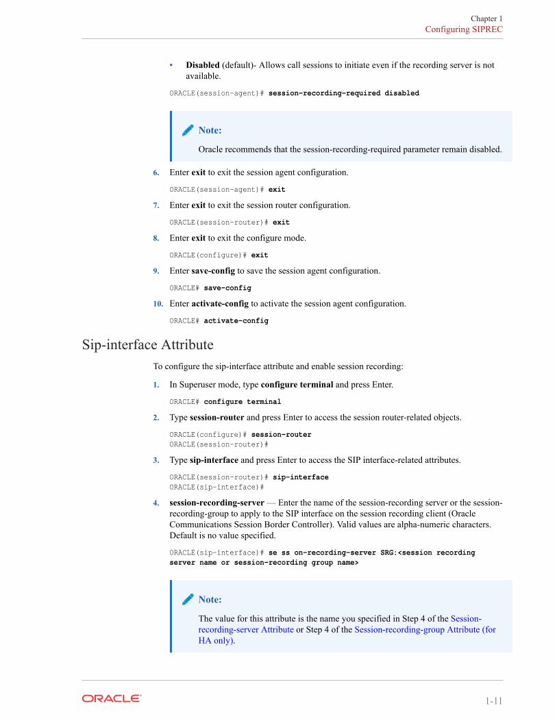
Sip-interface AttributeTo configure the sip-interface attribute and enable session recording:
1. In Superuser mode, type configure terminal and press Enter.
ORACLE# configure terminal
2. Type session-router and press Enter to access the session router-related objects.
ORACLE(configure)# session-routerORACLE(session-router)#
3. Type sip-interface and press Enter to access the SIP interface-related attributes.
ORACLE(session-router)# sip-interfaceORACLE(sip-interface)#
4. session-recording-server — Enter the name of the session-recording server or the session-recording-group to apply to the SIP interface on the session recording client (OracleCommunications Session Border Controller). Valid values are alpha-numeric characters.Default is no value specified.
ORACLE(sip-interface)# se ss on-recording-server SRG:<session recording server name or session-recording group name>
Note:
The value for this attribute is the name you specified in Step 4 of the Session-recording-server Attribute or Step 4 of the Session-recording-group Attribute (forHA only).
Chapter 1Configuring SIPREC
1-11

5. session-recording-required — Enter whether or not you want a call to be accepted by theOracle Communications Session Border Controller if recording is not available. Validvalues are:
• Enabled - Restricts call sessions from being initiated when a recording server is notavailable.
• Disabled (default)- Allows call sessions to initiate even if the recording server is notavailable.
ORACLE(sip-interface)# session-recording-required disabled
Note:
Oracle recommends that the session-recording-required parameter remain disabled.
6. Enter exit to exit the SIP interface configuration.
ORACLE(sip-interface)# exit
7. Enter exit to exit the session router configuration.
ORACLE(session-router)# exit
8. Enter exit to exit the configure mode.
ORACLE(configure)# exit
9. Enter save-config to save the SIP interface configuration.
ORACLE# save-config
10. Enter activate-config to activate the SIP interface configuration.
ORACLE# activate-config
P-Asserted Identity and Diversion Headers in SIPRECMetadata
The Oracle Communications Session Border Controller supports some call transfer scenarios inwhich the contents of the P-Asserted-Identity, Diversion and History-info headers must beincluded in the SIPREC metadata for in-dialog requests (re-INVITE and UPDATE) as well asinitial requests.
During a Communication Session (CS) between user-agents, Oracle Communications SessionBorder Controllerupdates the SRS, for in-dialog requests like Re-INVITE and UPDATE, in theRecording Session (RS). In call transfer scenarios, the participant information available in theheaders is updated in the extension data under SIPREC Metadata. When the option disable-re-invite-on-update is configured in the session-agent, sip-interface, or real-config configurationelements, the SBC restricts the Re-INVITE to RS for the in-dialog UPDATE in CS.
You will have to configure the system with the SipHeaderExtensionMetadata.spl (SBCProcessing Language) plugin for the disable-re-invite-on-update option to work. For moreinformation, see Inserting SIP headers into SIPREC Metadata.
Consider a call transfer scenario between User Agent A (UA-A) and User Agent C (UA-C).The session will be recorded by Oracle Communications Session Border Controlleracting as anSRC and an SRS. The SRS does not record the session with User Agent B. In order to recordthe session between UA-A and UA-C it is vital to correctly identify the User Agents in the
Chapter 1Configuring SIPREC
1-12

session. The system uses the headers in the metadata to reflect the identities of the participatingagents.
The header information such as P-Asserted Identity, Diversion and History-info forINVITE/Re-INVITE and UPDATE cases will be updated in the extension data of participantxml element.
You can configure the option disable-re-invite-on-update to stop the Re-INVITE requeststowards the Recording Session (RS) for any in-dialog UPDATE in Communication Session(CS). This option can be configured under a specified sip-interface , realm-config , or asession-agent .
ORACLE#(session-agent) options +disable-re-invite-on-update
Session-agent takes precedence over realm-config, and realm-config takes precedence oversip-interface.
Metadata ContentsThe recording metadata contains a set of related elements which define the recording session. Arecording session may contain zero or more communication sessions and/or communicationsession groups. A communication session represents a call instance; a communication sessiongroup represents a related group of communication sessions. A recording session is composedof a sequence of complex element types. Not all element types are required to describe arecording session initiated from the Oracle Communications Session Border Controller. Therecording session XML schema defines the following element types:
• dataMode - partial or complete metadata description (required)
• group - a collection of related communication sessions
• session - a single communication session of two or more participants (required)
• participant - a SIP endpoint representation (required)
• stream - a media stream
Chapter 1Configuring SIPREC
1-13

• extensiondata - application specific data outside of the SIPREC scope.
The recording agent generates dataMode, session, participant, and stream elements. Extensiondata is attached to other elements within the metadata through the use of the parent attribute.The recording metadata is defined as a sequence of element types; therefore all associationsbetween elements are represented as references to element identifiers.
The state of the metadata within a recording session reflects the state of the communicationsession(s) which is being recorded. SIPREC implements stop-times and reason codes whencommunication sessions end within a recording session. Once a communication session,participant, or media stream has been marked as 'stopped' and accepted by the SRS, themetadata item is removed from the current metadata state. In addition, media lines within theSDP or the recording session may be re-used/re-labeled for reuse if new communicationsessions and media streams are created within the recording session.
The XML schema for the recording metadata is defined in the IETF draft RFC draft-ram-siprec-metadata-format-02 [7].
The ACLI command to show recorded metadata is show rec. For more information on thiscommand see the section, Show rec.
Show Commands for Recording SessionsThe Oracle Communications Session Border Controller allows you to utilize the followingshow commands via the ACLI to display statistical information about recording sessions:
• show rec
• show rec redundancy
Show recThe show rec command displays the count of all metadata objects in sessions managed by therecording agent. These statistics include metadata monitored over an active period of time andover a lifetime period (where lifetime totals reflect from the last reboot of the OracleCommunications Session Border Controller to the present time). The following example showsthe use of this command.
1. Log into the Oracle Communications Session Border Controller as a User or Superuser.
ACMEPACKET> enableACMEPACKET(enable)#
2. Type show rec and press Enter to display the recording metadata statistics. The followingoutput is an example of the show rec command.
ACMEPACKET(enable)# show rec
Show rec output
13:49:44-81645Recording Agent Status -- Period -- -------- Lifetime -------- Active High Total Total PerMax HighRec Sessions 0 1 1 1 1 1Comm Groups 0 0 0 0 0 0Comm Sessions 0 1 1 1 1 1Media Streams 0 2 2 2 2 2Participants 0 2 2 2 2 2
The following table describes the metadata objects in the show rec command output.
Chapter 1Configuring SIPREC
1-14

Object Description
Rec Sessions Number of recording sessions during an active period of time and over alifetime period.
Comm Groups Number of active communication session recording groups during an activeperiod of time and over a lifetime period.
Comm Sessions Number of active communication sessions during an active period of timeand over a lifetime period.
Media Streams Number of active media streams during an active period of time and over alifetime period.
Participants Total number of participants in session recordings during an active period oftime and over a lifetime period.
Show rec redundancyThe show rec redundancy command displays information for session recording serverstatistics when the Oracle Communications Session Border Controller is configured for HA.These statistics include metadata monitored over an active period of time and over a lifetimeperiod (where lifetime totals reflect from the last reboot of the Oracle Communications SessionBorder Controller to the present time) on both the primary and redundant OracleCommunications Session Border Controller. The following example shows the use of thiscommand.
1. Log into the Oracle Communications Session Border Controller as a User or Superuser.
ACMEPACKET> enableACMEPACKET(enable)#
2. Type show rec redundancy and press Enter to display the session recording serverstatistics for Oracle Communications Session Border Controllers in HA mode. Thefollowing output is an example of the show rec redundancy command.
ACMEPACKET(enable)# show rec redundancy
Show rec redundancy output
Primary System
13:49:44-81645Recording Agent Status -- Period -- -------- Lifetime -------- Active High Total Total PerMax HighRec Sessions 0 1 1 1 1 1Comm Groups 0 0 0 0 0 0Comm Sessions 0 1 1 1 1 1Media Streams 0 2 2 2 2 2Participants 0 2 2 2 2 2
Redundant System13:49:44-81646Recording Agent Status -- Period -- -------- Lifetime -------- Active High Total Total PerMax HighRec Sessions 0 1 1 1 1 1Comm Groups 0 0 0 0 0 0Comm Sessions 0 1 1 1 1 1Media Streams 0 2 2 2 2 2Participants 0 2 2 2 2 2
The following table describes the session recording server statistics in the show recredundancy command output.
Chapter 1Configuring SIPREC
1-15

Object Description
Rec Sessions Number of recording sessions during an active period of time and over alifetime period.
Comm Groups Number of active communication session recording groups during an activeperiod of time and over a lifetime period.
Comm Sessions Number of active communication sessions during an active period of timeand over a lifetime period.
Media Streams Number of active media streams during an active period of time and over alifetime period.
Participants Total number of participants in session recordings during an active period oftime and over a lifetime period.
Inserting SIP Headers into SIPREC MetadataThe SIPREC Extension Data Enhancements SPL provides additional header information in theoriginating SIP messages metadata sent to the Interactive Session Recorder. With this SPL, youcan introduce more options for recording policy decisions when using the SIPREC feature ofthe Oracle Communications Session Border Controller. The enhanced metadata also allows forthe realm-id to be used as an indicator of the recording account. The SPL also providesconfigurable values that collect additional header information to store in the metadata.
When the SPL is configured, the SIPREC Extension Data Enhancements SPL is only triggeredupon INVITE/UPDATE requests, and stores the additional header information in the metadatathat is sent to the Net-Net Interactive Session Recorder (NN-ISR). Metadata is a XML MIMEattachment that describes recording details to the Net-Net ISR.
By default, the Extension-Headers SPL option collects only the Request-URI in a receivedINVITE. You can store additional header information by configuring the SPL with additionalattributes in the spl-options under the global spl-config.. The values must be in a commaseparated list enclosed in double quotation marks. For example:
Extension-Headers="P-Asserted-Identity,Diversion"
This configuration of the Extension-Headers option adds the originating Request-URI alongwith all P-Asserted-Identity and Diversion-Headers into the participant section of the metadata.
You can configure the LRE-Identifier SPL option to add an identifier of the logical remoteentity (LRE) that triggered the recording to the <apkt:realm> element of the extensionmetadata. When configured with a value added, the value appears in place of the identifier.When configured without a value, the identifier of the logical remote entity is used. Forexample, session-agent will be the hostname, realm-config will be the realm, and sip-interfacewill be the realm name.
Note:
Both options are required for the SPL to function properly.
Sample MetadataThe sample below shows metadata with new extension data added by the SIPREC ExtensionData Enhancements SPL (New metadata appears in bold):
Chapter 1Configuring SIPREC
1-16
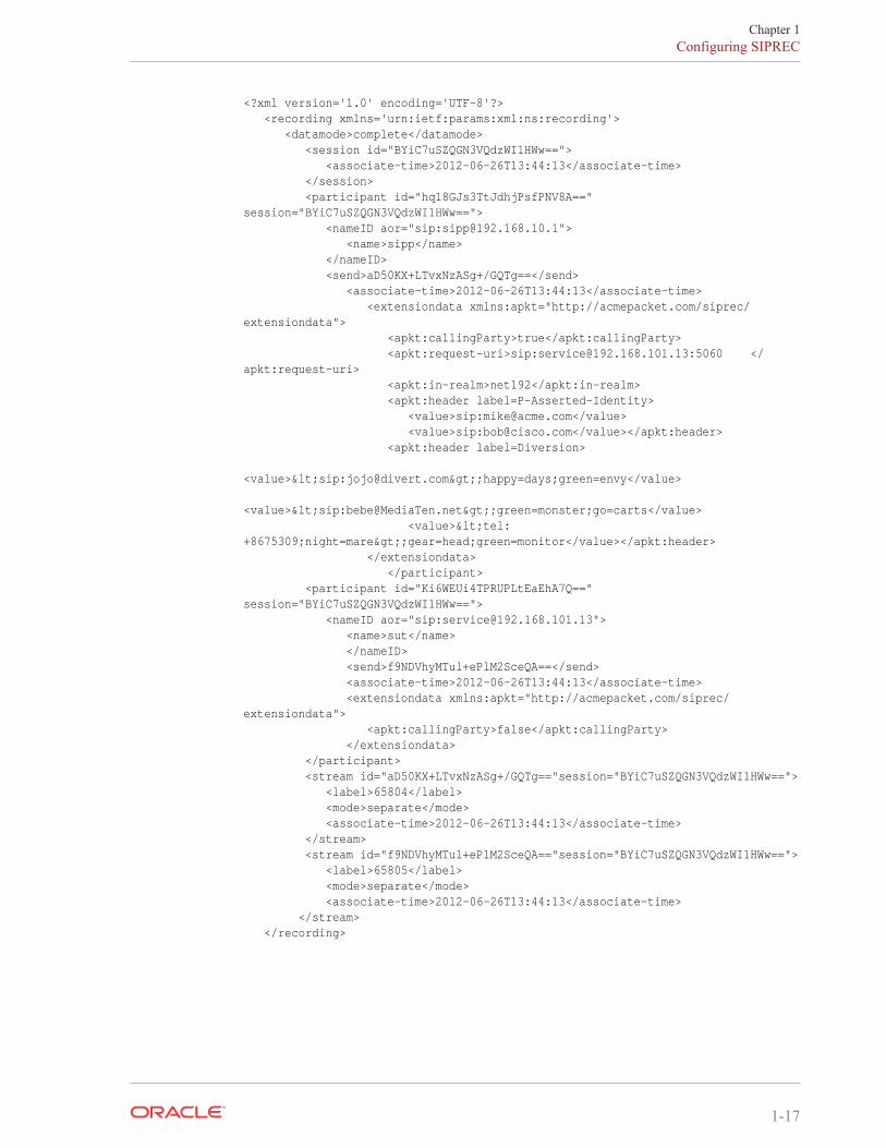
<?xml version='1.0' encoding='UTF-8'?> <recording xmlns='urn:ietf:params:xml:ns:recording'> <datamode>complete</datamode> <session id="BYiC7uSZQGN3VQdzWI1HWw=="> <associate-time>2012-06-26T13:44:13</associate-time> </session> <participant id="hq18GJs3TtJdhjPsfPNV8A==" session="BYiC7uSZQGN3VQdzWI1HWw=="> <nameID aor="sip:[email protected]"> <name>sipp</name> </nameID> <send>aD50KX+LTvxNzASg+/GQTg==</send> <associate-time>2012-06-26T13:44:13</associate-time> <extensiondata xmlns:apkt="http://acmepacket.com/siprec/extensiondata"> <apkt:callingParty>true</apkt:callingParty> <apkt:request-uri>sip:[email protected]:5060 </apkt:request-uri> <apkt:in-realm>net192</apkt:in-realm> <apkt:header label=P-Asserted-Identity> <value>sip:[email protected]</value> <value>sip:[email protected]</value></apkt:header> <apkt:header label=Diversion> <value><sip:[email protected]>;happy=days;green=envy</value> <value><sip:[email protected]>;green=monster;go=carts</value> <value><tel:+8675309;night=mare>;gear=head;green=monitor</value></apkt:header> </extensiondata> </participant> <participant id="Ki6WEUi4TPRUPLtEaEhA7Q==" session="BYiC7uSZQGN3VQdzWI1HWw=="> <nameID aor="sip:[email protected]"> <name>sut</name> </nameID> <send>f9NDVhyMTul+ePlM2SceQA==</send> <associate-time>2012-06-26T13:44:13</associate-time> <extensiondata xmlns:apkt="http://acmepacket.com/siprec/extensiondata"> <apkt:callingParty>false</apkt:callingParty> </extensiondata> </participant> <stream id="aD50KX+LTvxNzASg+/GQTg=="session="BYiC7uSZQGN3VQdzWI1HWw=="> <label>65804</label> <mode>separate</mode> <associate-time>2012-06-26T13:44:13</associate-time> </stream> <stream id="f9NDVhyMTul+ePlM2SceQA=="session="BYiC7uSZQGN3VQdzWI1HWw=="> <label>65805</label> <mode>separate</mode> <associate-time>2012-06-26T13:44:13</associate-time> </stream> </recording>
Chapter 1Configuring SIPREC
1-17

Configure SIP Headers for SIPREC MetadataTo get more detailed information about a recorded session, you can add more SIP headerswithin the SIPREC metadata by way of the Extension-Headers option. The default behaviorstores only the Request-URI and realm-id.
You must configure the Extension-Headers option at the global level under spl-config becausethe session-agent, realm-config, and sip-interface configurations do not recognize the option.The first time you configure one or more extension headers, you need only to save and activatethe configuration for the system to recognize the extension headers. When you modify theexisting SPL extension header list you need to save and activate the configuration, and rebootthe system for the changes to take effect. Real Time Configuration (RTC) does not apply toextension header options.
1. Type spl-options +Extension-Headers=”<value>” , where <value> is the additionalheader information to store, and press Enter.
ACMESYSTEM(spl-config)# spl-options +Extension-Headers=”P-Asserted-Identity,Diversion”
2. Type done to save the configuration.
SIPREC Recording Session RefreshThe Oracle Communications Session Border Controller provides for periodic in-dialogOPTIONS request/response exchanges to test the availability of the recording session dialog.
As shown below, and previously explained, establishment of a SIPREC session involves thecreation of three distinct dialogs: a recording session dialog between the SIPREC client andSIPREC server, a SIP dialog between the calling party (A) and the SBC (acting as a B2BUA),and another SIP dialog between the SBC (acting as a B2BUA) and the called party (B). Thetwo SIP dialogs are viewed conceptually as a single communications session dialog.
Both the call recording and the communication session dialogs are triggered by an INVITE atthe SIPREC client. Upon reception, the recording client (the SBC) buffers the original INVITE,and sends a copy if it, along with call-related meta-data to the recording server. A 200 OKresponse from the server establishes the recording session dialog that will carry replicated callcontent; signalling information is conveyed by the metadata in the recording dialog. Afterestablishing the recording session, the client transmits the buffered INVITE to the called partyto begin establishing the communications session dialog.
In the absence of a 200 OK response, the recording client is required to reject the offeredINVITE with a 503 (Service Unavailable) SIP error code and an accompanying Reason headerindicating that the recording session could not be established.
After establishing the recording session dialog, the client does not monitor its connection state.Its only opportunity to verify the state occurs after the termination of the communicationssession dialog, which triggers a client-originated BYE to the recording server. Reception of a200 OK/ACK confirms the persistence of the recording session, while the lack ofacknowledgement indicates the failure of the recording session at some unspecified point intime.
This failure to identify a prematurely terminated recording session has caused service providersand some regulatory agencies to require timely recognition of a failed call recording dialog.
Chapter 1SIPREC Recording Session Refresh
1-18

Release S-CZ7.2.0, and later releases, address this requirement by providing for the exchangeof periodic in-dialog OPTIONS request/response exchanges to test the availability of therecording session dialog.
Timer_BSection 17.1.1.2 of RFC 3261, SIP: Session Initiation Protocol describes a TIMER_B, the SIPINVITE transaction timer, which specifies the maximum interval between an INVITE requestand response. The RFC suggests a default value of 32 seconds. Depending on the installedrelease version, two ACLI commands, trans-expire and initial-inv-trans-expire, provideuser control over the TIMER_B value at both the SIP global level and the SIP interface level.Use these commands to adjust TIMER_B values if required.
OPTIONS Request/ResponseAvailability of the recording session is tested by an in-dialog SIP OPTIONS request/responseexchange initiated by the call recording client and completed by the call recording server. If theOPTIONS exchange is enabled, two timers are set when the recording session dialog isestablished: a refresh-timer that specifies the interval between OPTIONS requests sent by thecall recording client, and a response-timer that specifies the maximum interval between theOPTIONS request and the OPTIONS response. The response-timer is set to the smaller of theconfigured TIMER_B or refresh-timer values.
Expiration of the refresh-timer results in the transmission of an OPTIONS request to the callrecording server. The server, in turn, must reply with a 200 OK OPTIONS response prior to theexpiration of the response-timer. In the event of a positive response, the call recording clientrestarts the refresh-timer, and re-issues the OPTIONS request when the timer next expires.
In the event that the call recording server response is non-positive, that is either
1. not received prior to the expiration of the response timer, or
2. a non-2xx OPTIONS response
the SBC terminates the session recording dialog and records the termination in the event log.
Typically, a SIPREC environment contains multiple recorders configured to record acommunications session dialog, consequently the communications session should be terminatedonly when all recording dialogs in the call recording server have terminated. At that point thecommunications session dialog is torn down with a 503 (Service Unavailable) error report.
Recording Session Refresh ConfigurationUse the following procedure to enable a SIP OPTIONS request/response mechanism used todetect a prematurely terminated call recording session dialog.
1. session-recording-required—ensure that this parameter is enabled.This is a prerequisite for the provision of recording session refresh services.
2. refresh-interval—use this parameter to both enable the SIP OPTIONS request/responsemechanism, and to assign a value to the refresh-timer, which measures the maximumallowed interval (in seconds) between the OPTIONS request sent by the call-recordingclient and the OPTIONS response returned by the call-recording server.By default, refresh-interval is set to 0, which disables detection of a failed recordingsession dialog.Assignment of any non-zero value enables detection and sets the allowable intervalbetween OPTIONS requests and responses.
Chapter 1SIPREC Recording Session Refresh
1-19

Consult local policy and regulatory requirements when specifying the refresh-intervalvalue.
ACMEPACKET(session-router)# refresh-interval 12ACMEPACKET(session-recording-server)#
Codec NegotiationIn a SIPREC environment, it is assumed that the recording ecosystem provides transcodingmedia servers for which media calls can be redirected to, relieving the issue of codec matchingfrom the recording servers. However, if transcoding media servers are not provided, theresponsibility for transcoding falls on the recording server or the recording client in a SIPRECenvironment. The Oracle Communications Session Border Controller/SRC is required toimpose some policy decisions on the codec negotiation between the three, or more, end-points.Specifically, the codec negotiation between the two participants and the recording server issubject to additional policy actions.
The SDP answer from the SRS may not agree with the media flows established in thecommunication session between UA-A and UA-B. If UA-A and UA-B agree to use G729, yetthe SRS's answer indicates no support for G729, the SRS is then unable to interpret the mediastreams. The SDP offer forwarded to the called party (in this case UA-B) limits the codecchoices to those supported by the SRS.
Note:
The recording agent forwards the original codec offer to the SRS prior to sending theinvite to the UA-B. The SRS responds with the SDP answer, indicating the codec listmost desirable to the SRS. The codec list in the answer is then forwarded to UA-B.This allows three parties in a conference call to participate in the negotiation of thecodecs among the supported formats only.
SIPREC Call FlowsThis section provides examples of call flow scenarios that can occur in a SIPREC environment.SIP recording call flow examples include:
For Selective Recording:
• Normal Call (recording required)
• Normal Call (recording not required)
• Early Media Call (recording not required)
• REFER Pass-Through Call (REFER handled by User Agent)
• REFER Call (REFER handled by the Oracle Communications Session Border Controller)
• SRS Indicates Busy in Call (recording not required)
Chapter 1Codec Negotiation
1-20

Note:
REFER is a SIP method indicating that the recipient (identified by the Request-URI) should contact a third party using the contact information provided in therequest.
Selective Recording
Normal Call (recording required)The following illustration shows a normal call using selective recording with recordingrequired. For SDP and Metadata information in Notes 1 and 2 , see Sample SDP and Metadata.
I
Call Flow Description
① UA-A sends INVITE to OracleCommunications Session Border Controller.
⑩ RTP stream initiated between OracleCommunications Session Border Controller andUA-B.
Chapter 1SIPREC Call Flows
1-21

Call Flow Description
② Oracle Communications Session BorderController forwards INVITE with SDP andmetadata to SRS.
⑪ RTP stream initiated between OracleCommunications Session Border Controller andSRS.
③ SRS responds with OK to OracleCommunications Session Border Controller.
⑫ UA-A sends BYE to Oracle CommunicationsSession Border Controller.
④ Oracle Communications Session BorderController sends INVITE to UA-B.
⑬ Oracle Communications Session BorderController responds with OK to UA-A.
⑤ UA-B responds with OK to OracleCommunications Session Border Controller.
⑭ Oracle Communications Session BorderController sends BYE to Oracle CommunicationsSession Border Controller.
⑥ Oracle Communications Session BorderController sends re-INVITE with SDP andmetadata changes to SRS.
⑮ Oracle Communications Session BorderController responds with OK to UA-A.
⑦ SRS responds with OK to OracleCommunications Session Border Controller.
⑯ Oracle Communications Session BorderController sends BYE to UA-B.
⑧ Oracle Communications Session BorderController forwards OK response to UA-A.
⑰ UA-B responds with OK to OracleCommunications Session Border Controller.
⑨ RTP stream initiated between UA-A and OracleCommunications Session Border Controller.
⑱ Oracle Communications Session BorderController sends BYE to SRS.⑲ SRS responds with OK to OracleCommunications Session Border Controller.
Sample SDP and MetadataThe following sample SDP and Metadata pertain to Notes 1 and 2 in the previous Call Flowdiagram.
--[Note 1]------------------------------Content-Type: application/sdpv=0o=- 171 213 IN IP4 10.0.0.2s=-c=IN IP4 10.0.0.1t=0 0m=audio 6000 RTP/AVP 0a=rtpmap:0 PCMU/8000a=label:1
Content-Type: application/rs-metadata+xmlContent-Disposition: recording-session<?xml version='1.0' encoding='UTF-8'?><recording xmlns='urn:ietf:params:xml:ns:recording'> <dataMode>complete</dataMode> <session id="urn:uuid:79b2fcd8-5c7f-455c-783f-db334e5d57d0"> <start-time>2011-06-27T17:03:57</start-time> </session> <participant id="urn:uuid:10ac9063-76b7-40bb-4587-08ba290d7327" session="urn:uuid:79b2fcd8-5c7f-455c-783f-db334e5d57d0"> <aor>sip:[email protected]</aor> <name>sipp </name> <send>urn:uuid:07868c77-ef8e-4d6f-6dd5-a02ff53a1329</send> <start-time>2011-06-27T17:03:57</start-time> </participant> <participant id="urn:uuid:797c45f5-e765-4b12-52b0-d9be31138529"
Chapter 1SIPREC Call Flows
1-22

session="urn:uuid:79b2fcd8-5c7f-455c-783f-db334e5d57d0"> <aor>sip:[email protected]</aor> <name>sut </name> </participant> <stream id="urn:uuid:4a72a1ed-abb2-4d7c-5f4d-6d4c36e2d4ec" session="urn:uuid:79b2fcd8-5c7f-455c-783f-db334e5d57d0"> <mode>separate</mode> <start-time>2011-06-27T17:03:57</start-time> <label>1</label> </stream></recording>
--[Note 2]------------------------------Content-Type: application/sdpv=0o=- 171 213 IN IP4 10.0.0.2s=-c=IN IP4 10.0.0.1t=0 0m=audio 6000 RTP/AVP 0a=rtpmap:0 PCMU/8000a=label:1m=audio 6002 RTP/AVP 0a=rtpmap:0 PCMU/8000a=label:2
Content-Type: application/rs-metadata+xmlContent-Disposition: recording-session<?xml version='1.0' encoding='UTF-8'?><recording xmlns='urn:ietf:params:xml:ns:recording'> <dataMode>partial</dataMode> <session id="urn:uuid:79b2fcd8-5c7f-455c-783f-db334e5d57d0"> <start-time>2011-06-27T17:03:57</start-time> </session> <participant id="urn:uuid:797c45f5-e765-4b12-52b0-d9be31138529" session="urn:uuid:79b2fcd8-5c7f-455c-783f-db334e5d57d0"> <aor>sip:[email protected]</aor> <name>sut </name> <send>urn:uuid:4a72a1ed-abb2-4d7c-5f4d-6d4c36e2d4ec</send> <start-time>2011-06-27T17:03:58</start-time> </participant> <stream id="urn:uuid:07868c77-ef8e-4d6f-6dd5-a02ff53a1329" session="urn:uuid:79b2fcd8-5c7f-455c-783f-db334e5d57d0"> <mode>separate</mode> <start-time>2011-06-27T17:03:58</start-time> <label>2</label> </stream></recording>
Normal Call (recording not required)The following illustration shows a normal call using selective recording with recordingoptional.
Chapter 1SIPREC Call Flows
1-23

Call Flow Description
① UA-A sends INVITE to OracleCommunications Session Border Controller.
⑧ RTP stream initiated between OracleCommunications Session Border Controller and SRS.
② Oracle Communications Session BorderController forwards INVITE to UA-B.
⑨ UA-A sends BYE to Oracle CommunicationsSession Border Controller.
③ UA-B responds with OK to OracleCommunications Session Border Controller.
⑩ Oracle Communications Session Border Controllerresponds with OK to UA-A.
④ Oracle Communications Session BorderController forwards OK response to UA-A.
⑪ Oracle Communications Session Border Controllersends BYE to UA-B.
⑤ Oracle Communications Session BorderController sends INVITE with SDP andmetadata to SRS.
⑫ UA-B responds with OK to OracleCommunications Session Border Controller.
⑥ SRS responds with OK to OracleCommunications Session Border Controller.
⑬ Oracle Communications Session Border Controllersends BYE to SRS.
⑦ RTP stream initiated between UA-A, OracleCommunications Session Border Controller, and UA-B.
⑭ SRS responds with OK to Oracle CommunicationsSession Border Controller.
Early Media Call (recording not required)The following illustration shows an early media call using selective recording with recordingoptional.
Chapter 1SIPREC Call Flows
1-24

Call Flow Description
① UA-A sends INVITE to OracleCommunications Session Border Controller.
⑩ UA-B responds with OK to OracleCommunications Session Border Controller.
② Oracle Communications Session BorderController forwards INVITE to UA-B.
⑪ Oracle Communications Session BorderController forwards OK to UA-A.
③ UA-B sends 180 and SDP to OracleCommunications Session Border Controller.
⑫ Oracle Communications Session BorderController sends re-INVITE with SDP andmetadata changes to SRS.
④ Oracle Communications Session BorderController sends INVITE with SDP and metadatato SRS.
⑬ SRS responds with OK to OracleCommunications Session Border Controller.
⑤ SRS responds with OK to OracleCommunications Session Border Controller.
⑭ UA-A sends BYE to Oracle CommunicationsSession Border Controller.
⑥ Oracle Communications Session BorderController sends 180 with SDP to UA-A.
⑮ Oracle Communications Session BorderController responds with OK to UA-A.
⑦ RTP stream initiated between OracleCommunications Session Border Controller andUA-A.
⑯ Oracle Communications Session BorderController sends BYE to UA-B.
⑧ RTP stream initiated between OracleCommunications Session Border Controller andUA-B.
⑰ UA-B responds with OK to OracleCommunications Session Border Controller.
Chapter 1SIPREC Call Flows
1-25

Call Flow Description
⑨ RTP stream initiated between OracleCommunications Session Border Controller andSRS.
⑱ Oracle Communications Session BorderController sends BYE to SRS.
⑲ SRS responds with OK to OracleCommunications Session Border Controller.
REFER Pass-Through Call (REFER handled by User Agent)The following illustration shows a REFER pass-through call using selective recording and theUser Agent (UA) handling the REFER on the call. Recording is required in this call flow.
Call Flow Description
1 - UA-A sends INVITE to OracleCommunications Session Border Controller.
18 - UA-C responds with OK to OracleCommunications Session Border Controller.
2 - Oracle Communications Session BorderController forwards INVITE with SDP Offer andmetadata to SRS.
19 - Oracle Communications Session BorderController forwards OK response to UA-B.
Chapter 1SIPREC Call Flows
1-26

Call Flow Description
3 - SRS responds with OK to OracleCommunications Session Border Controller.
20 - Oracle Communications Session BorderController sends NOTIFY with OK reponse to UA-A.
4 - Oracle Communications Session BorderController sends INVITE to UA-B.
21 - Oracle Communications Session BorderController sends re-INVITE to SRS with new SDPand metadata, adds participant C, stops participantA .
5 - UA-B responds with OK to OracleCommunications Session Border Controller.
22 - SRS responds with OK to OracleCommunications Session Border Controller.
6 - Oracle Communications Session BorderController sends re-INVITE with SDP andmetadata changes to SRS.
23 - UA-A sends BYE to Oracle CommunicationsSession Border Controller.
7 - SRS responds with OK to OracleCommunications Session Border Controller.
24 - Oracle Communications Session BorderController responds with OK to UA-A.
8 - Oracle Communications Session BorderController forwards OK response to UA-A.
25 - Oracle Communications Session BorderController responds with OK to UA-A.
9 - RTP stream initiated between UA-A and OracleCommunications Session Border Controller.
26 - RTP stream initiated between OracleCommunications Session Border Controller andUA-B.
10 - RTP stream initiated between OracleCommunications Session Border Controller andUA-B.
27 - RTP stream initiated between OracleCommunications Session Border Controller andUA-C.
11 - RTP stream initiated between OracleCommunications Session Border Controller andSRS.
28 - RTP stream initiated between OracleCommunications Session Border Controller andSRS.
12 - UA-A sends REFER-TO: C to OracleCommunications Session Border Controller.
29 - UA-C sends BYE to Oracle CommunicationsSession Border Controller.
13 - Oracle Communications Session BorderController forwards REFER-TO: C to UA-B.
30 - Oracle Communications Session BorderController responds with OK to UA-C.
14 - UA-B responds with 202 ACCEPTED toOracle Communications Session Border Controller.
31 - Oracle Communications Session BorderController sends BYE to UA-B.
15 - Oracle Communications Session BorderController forwards 202 ACCEPTED to UA-A.
32 - UA-B responds with OK to OracleCommunications Session Border Controller.
16 - UA-B sends INVITE TO: C to OracleCommunications Session Border Controller.
33 - Oracle Communications Session BorderController sends BYE to SRS
17 - Oracle Communications Session BorderController sends INVITE to UA-C.
34 - SRS responds with OK to OracleCommunications Session Border Controller.
REFER Call (REFER handled by Oracle Communications SessionBorder Controller)
The following illustration shows a call using selective recording and the Session BorderController (Oracle Communications Session Border Controller) handling the REFER on thecall. Recording is required in this call flow.
Chapter 1SIPREC Call Flows
1-27

Call Flow Description
1 - UA-A sends INVITE to OracleCommunications Session Border Controller.
16 - Oracle Communications Session BorderController sends NOTIFY with OK response toUA-A.
2 - Oracle Communications Session BorderController forwards INVITE with SDP Offer andmetadata to SRS.
17 - UA-A sends BYE to Oracle CommunicationsSession Border Controller.
3 - SRS responds with OK to OracleCommunications Session Border Controller.
18 - Oracle Communications Session BorderController responds with OK to UA-A.
4 - Oracle Communications Session BorderController sends INVITE to UA-B.
19 - Oracle Communications Session BorderController sends re-INVITE to UA-B.
5 - UA-B responds with OK to OracleCommunications Session Border Controller.
20 - UA-B responds with OK to OracleCommunications Session Border Controller.
6 - Oracle Communications Session BorderController sends re-INVITE with SDP andmetadata changes to SRS.
21 - Oracle Communications Session BorderController sends re-INVITE to SRS with new SDPand metadata.
7 - SRS responds with OK to OracleCommunications Session Border Controller.
22 - SRS responds with OK to OracleCommunications Session Border Controller.
8 - Oracle Communications Session BorderController forwards OK response to UA-A.
23 - RTP stream initiated between OracleCommunications Session Border Controller andUA-B.
Chapter 1SIPREC Call Flows
1-28

Call Flow Description
9 - RTP stream initiated between UA-A and OracleCommunications Session Border Controller.
24 - RTP stream initiated between OracleCommunications Session Border Controller andUA-C.
10 - RTP stream initiated between OracleCommunications Session Border Controller andUA-B.
25 - RTP stream initiated between OracleCommunications Session Border Controller andSRS.
11 - RTP stream initiated between OracleCommunications Session Border Controller andSRS.
26 - UA-C sends BYE to Oracle CommunicationsSession Border Controller.
12 - UA-A sends REFER-TO: C to OracleCommunications Session Border Controller.
27 - Oracle Communications Session BorderController responds with OK to UA-C.
13 - Oracle Communications Session BorderControllerOracle Communications Session BorderController responds with 202 ACCEPTED to UA-A.
28 - Oracle Communications Session BorderController sends BYE to UA-B.
14 - Oracle Communications Session BorderController sends INVITE to UA-C.
29 - UA-B responds with OK to OracleCommunications Session Border Controller.
15 - UA-C responds with OK to OracleCommunications Session Border Controller.
30 - Oracle Communications Session BorderController sends BYE to SRS.31 - SRS responds with OK to OracleCommunications Session Border Controller.
SRS Indicates Busy in Call (recording not required)The following illustration shows the Session Recording Server (SRS) is BUSY for a callsession. Recording is not required in this call flow.
Chapter 1SIPREC Call Flows
1-29

Call Flow Description
① UA-A sends INVITE to OracleCommunications Session Border Controller.
⑨ Oracle Communications Session Border Controllersends INVITE to SRS2 with SDP and metadata.
② Oracle Communications Session BorderController forwards INVITE to UA-B.
⑩ SRS2 responds with OK to OracleCommunications Session Border Controller.
③ UA-B responds with OK to OracleCommunications Session Border Controller.
⑪ RTP stream initiated between OracleCommunications Session Border Controller andSRS2.
④ Oracle Communications Session BorderController forwards OK response to UA-A.
⑫ UA-A sends BYE to Oracle CommunicationsSession Border Controller.
⑤ Oracle Communications Session BorderController sends INVITE to SRS1 with SDP andmetadata.
⑬ Oracle Communications Session Border Controllerresponds with OK to UA-A.
⑥ SRS1 responds to Oracle CommunicationsSession Border Controller with 436 BUSYHERE.
⑭ Oracle Communications Session Border Controllersends BYE to UA-B.
⑦ RTP stream initiated between UA-AandOracle Communications Session BorderController.
⑮ UA-B responds with OK to OracleCommunications Session Border Controller.
⑧ RTP stream initiated between OracleCommunications Session Border Controller andUA-B.
⑯ Oracle Communications Session Border Controllersends BYE to SRS2.
Chapter 1SIPREC Call Flows
1-30

Call Flow Description
⑰ SRS2 responds with OK to OracleCommunications Session Border Controller.
Call Transfer Scenario (recording required)The following illustration shows the Re-INVITE from Oracle Communications Session BorderController to SRS on receiving in-dialog-requests INVITE/ UPDATE/ Re-INVITE during callsession. Recording is required in this call flow.
Call Flow Description
1 - UA-A sends INVITE to OracleCommunications Session Border Controller.
11 - UA-B responds with OK to OracleCommunications Session Border Controller.
2 - Oracle Communications Session BorderController updates the INVITE message to theMetadata in SRS.
12 - Oracle Communications Session BorderController forwards OK to UA-A..
3 - SRS responds with OK to OracleCommunications Session Border Controller.
13 - Oracle Communications Session BorderController sends a re-INVITE to SRS in RecordingSession.
4 - Oracle Communications Session BorderController sends an INVITE to UA-B.
14 - SRS responds with OK to OracleCommunications Session Border Controller.
5 - UA-B responds with OK to OracleCommunications Session Border Controller.
15 - UA-A sends BYE to Oracle CommunicationsSession Border Controller.
Chapter 1SIPREC Call Flows
1-31

Call Flow Description
6 - Oracle Communications Session BorderController forwards OK response to UA-A.
16 - Oracle Communications Session BorderController forwards BYE to UA-B.
7 - Oracle Communications Session BorderController sends INVITE to SRS in RecordingSession.
17 - UA-B responds with OK to OracleCommunications Session Border Controller.
8 - SRS responds with OK to OracleCommunications Session Border Controller.
18 - Oracle Communications Session BorderController forwards OK to UA-B.
9 - UA-A sends an UPDATE message to OracleCommunications Session Border Controller.
19 - Oracle Communications Session BorderController sends BYE to SRS in Recording Session.
10 - Oracle Communications Session BorderController forwards UPDATE message to UA-B.
20 - SRS responds with OK to OracleCommunications Session Border Controller inRecording Session.
Oracle Communications Session Monitor MediationEngine
The Oracle® Communications Session Monitor Mediation Engine is a platform that collectsSIP, DIAMETER, DNS and ENUM protocol message traffic received from CommunicationsSession Monitor Probes. A Probe is software run on COTS hardware; it is deployed within anetwork and collects packets from span/monitor ports on Ethernet switches, or receives IP-in-IP tunneled packet-traces from Oracle's Oracle Communications Session Border Controller. AProbe takes the protocol packets, prepends a receive timestamp and other information,encapsulates the packets, and passes them to the Communications Session Monitor via a secureconnection. After receiving protocol traffic from a Probe, the Communications Session Monitorstores the traffic in an internal database, and analyzes aggregated data to providecomprehensive multi-level monitoring, troubleshooting, and interoperability information.
In contrast to the Packet-Trace feature, message logging is performed by software, which sendsa copy of sent/received messages over UDP, or by saving such messages in a local file. Thecopy includes a timestamp, port/vlan information, and IP:port information, but all in ASCIIformat. Message Logging is performed after all decryption, meaning that SIP/TLS traffic cambe monitored. Because remote message logging sends the protocol messages over UDP, there isno guarantee or confirmation of delivery.
The Oracle Communications Session Border Controller provides support for CommunicationsMonitoring, a user-configurable capability that enables the system to function as aCommunications Session Monitor Probe. Acting as a Probe, or as an exporter, the OracleCommunications Session Border Controller can:
1. Establish an authenticated, persistent, reliable TCP connection between itself and one ormore Communications Session Monitor Mediation Engines.
2. Optionally ensure message privacy by encrypting the TCP connection using TLS.
3. Use the TCP connection to send a UTC-timestamped, unencrypted copy of a protocolmessage to the Communications Session Monitor Engine(s).
4. Accompany the copied message with related data to include: the port/vlan on which themessage was sent/received, local and remote IP:port information, and the transport layerprotocol.
Chapter 1Oracle Communications Session Monitor Mediation Engine
1-32

IPFIXThe Oracle Communications Session Border Controller uses the IPFIX suite of standards toexport protocol message traffic and related data to the Communications Session MonitorMediation Engine.
• RFC 5101, Specification of the IP Flow Information Export (IPFIX) Protocol for theExchange of IP Traffic Flow Information
• RFC 5102, Information Model for IP Flow Information Export
• RFC 5470, Architecture for IP Flow Information Export
• RFC 5655, Specification of the IP Flow Information Export (IPFIX) File Format
• RFC 5815, Definitions of Managed Objects for IP Flow Information Export
The IPFIX standards describe the use of templates to format the export of specific types ofprotocol traffic. The Oracle Communications Session Border Controller and theCommunications Session Monitor Mediation Engine share ten (10) pre-defined templates thatfacilitate protocol message exchange, and subsequent processing and analysis by theCommunications Session Monitor Engine.
The pre-defined templates are:
• incoming SIP/DNS over UDP
• incoming SIP over TCP
• incoming SIP over SCTP
• incoming DNS over UDP (entire IP and UDP header not included)
• outgoing SIP/DNS over UDP
• outgoing SIP over TCP
• outgoing SIP over SCTP
• outgoing DNS over UDP (entire IP and UDP header not included)
• media qos and flow record
• IPFIX handshake (used for connection establishment)
Communications Monitor ConfigurationCommunications Monitor configuration consists of the following steps.
1. Configuration of one or more Oracle Communications Session Border Controller/Palladionexporter/collector pairs.
Configuration of the -config object, which defines common operations across allinterfaces, is not required. Default values can be retained to enable standard service.
2. Optional assignment of a TLS profile to an exporter/collector pair.
Communication MonitorUse the following procedure to configure communication monitoring:
Chapter 1IPFIX
1-33

1. From superuser mode, use the following ACLI sequence to access comm-monitorconfiguration mode. From comm-monitor mode, you establish a connection between theOracle Communications Session Border Controller, acting as a exporter of protocolmessage traffic and related data, and an Oracle® Communications Session MonitorMediation Engine, acting as an information collector.
ACMEPACKET# configure terminalACMEPACKET(configure)# systemACMEPACKET(system)# system-configACMEPACKET(system-config)# comm-monitorACMEPACKET(comm-monitor)#
2. Use the state parameter to enable or disable communication monitoring.
Communication monitoring is disabled by default.
ACMEPACKET(comm-monitor)# state enabledACMEPACKET(comm-monitor)#
3. Use the sbc-group-id parameter to assign an integer value to the Oracle CommunicationsSession Border Controller, in its role as an information exporter.
Retain the default value (0) or assign another integer value.
ACMEPACKET(comm-monitor)# sbc-group-id 5ACMEPACKET(comm-monitor)#
4. If the network interface specified in Step 8 is a media interface, you can optionally useTLS to encrypt the exporter/collector connection.
To enable TLS encryption, use the tls-profile parameter to identify a TLS profile to beassigned to the network interface. The absence of an assigned TLS profile (the defaultstate) results in unencrypted transmission.
Refer to TLS Profile Configuration for configuration details.
ACMEPACKET(comm-monitor)# tls-profile commMonitorACMEPACKET(comm-monitor)#
5. Use the qos-enable parameter to enable or disable to export of RTP, SRTP, and QOS dataflow information.
ACMEPACKET(comm-monitor)# qos-enable enabledACMEPACKET(comm-monitor)#
6. Use the monitor-collector parameter to move to monitor-collector configuration mode.
While in this mode you identify a Communications Session Monitor Mediation Enginecollector by IP address and port number.
ACMEPACKET(comm-monitor)# monitor-collectorACMEPACKET(monitor-collector)#
7. Use the address and port parameters to specify the IP address and port number monitoredby a Communications Session Monitor Mediation Engine for incoming IPFIX traffic.
Enter an IPv4 address and a port number with values either 4739 (unsecured) or 4740(secured). The default value for the port is 4739.
ACMEPACKET(monitor-collector)# address 172.30.101.239ACMEPACKET(monitor-collector)# port 4739ACMEPACKET(monitor-collector)#
8. Use the network-interface parameter to specify the network interface that supports theTCP connection between the Oracle Communications Session Border Controller to theCommunications Session Monitor Mediation Engine.
Chapter 1Communications Monitor Configuration
1-34

To specify the wancom0 management interface:
ACMEPACKET(comm-monitor)# network-interface wancom0:0ACMEPACKET(comm-monitor)#
To specify a media interface:
ACMEPACKET(comm-monitor)# network-interface m01ACMEPACKET(comm-monitor)#
Note:
If configuring with a media interface, that interface must belong to a configuredrealm.
9. Use done and exit to return to comm-monitor configuration mode.
10. Use done, exit, and verify-config to complete configuration.
11. Repeat Steps 1 through 10 to configure additional as required.
TSCF Rekey Profile ConfigurationRekeying is a cryptographic technique that enhances security by enforcing the negotiation ofexisting keys on an ongoing secure connection. Rekeying can be either time-based, in whichcase new keys are negotiated at the expiration of a timer, or traffic-based, in which case newkeys are negotiated when a threshold byte count is exceeded.
Use the following procedure to configure an optional tscf-rekey-profile. Later, you will assignthe profile to a specific TSCF interface. If you do not intend to enforce re-keying, thisprocedure can be safely ignored.
1. From superuser mode, use the following command sequence to access tscf-rekey-profileconfiguration mode.
ACMEPACKET# configure terminalACMEPACKET(configure)# securityACMEPACKET(security)# tscfACMEPACKET(tscf)# tscf-rekey-profileACMEPACKET(tscf-rekey-profile)#
2. Use the name parameter to provide a unique identifier for this tscf-rekey-profile.
ACMEPACKET(tscf-rekey-profile)# name tscfRekey01ACMEPACKET(tscf-rekey-profile)#
3. Use the initiator parameter to identify the rekey initiator.
Supported values are client (default) | server (the Session Director)
ACMEPACKET(tscf-rekey-profile)# initiator clientACMEPACKET(tscf-rekey-profile)#
4. Use the max-rekey-time parameter to specify the maximum interval (in minutes) betweenre-keying operations.
Supported values are 0 (default) | 30 - 1440 (minutes)
The default value, 0, specifies that time-based rekeying is not enforced; other integervalues specify that time-based re-keying must be initiated by the tunnel endpointdesignated by the initiator parameter.
Chapter 1Communications Monitor Configuration
1-35

ACMEPACKET(tscf-rekey-profile)# max-rekey-time 30ACMEPACKET(tscf-rekey-profile)#
5. Use the max-rekey-data parameter to specify the maximum traffic exchange (measured inKb) between rekeying operations.
The default value, 0, specifies that traffic-based rekeying is not enforced; other integervalues specify that traffic-based re-keying must be initiated by the tunnel endpointdesignated by the initiator parameter.
ACMEPACKET(tscf-rekey-profile)# max-rekey-data 0ACMEPACKET(tscf-rekey-profile)#
6. Use done, exit, and verify-config to complete tscf-rekey-profile configuration.
7. Repeat Steps 1 through 6 to configure additional tscf-rekey-profiles as required.
TLS Profile ConfigurationUse the following procedure to configure a tls-profile that identifies the cryptographicresources, specifically certificates and protocols, required for the establishment of a secure/encrypted connection between the Oracle Communications Session Border Controller and theCommunications Session Monitor Mediation Engine.
1. From superuser mode, use the following command sequence to access tls-profileconfiguration mode.
ACMEPACKET# configure terminalACMEPACKET(configure)# securityACMEPACKET(security)# tls-profileACMEPACKET(tls-profile)#
2. Use the name parameter to provide a unique identifier for this tls-profile.
ACMEPACKET(tls-profile)# name commMonitorACMEPACKET(tls-profile)#
3. Use the required end-entity-certificate parameter to specify the name of the certificate-record configuration that identifies the credential (specifically, an X509.v3 certificate)offered by the Oracle Communications Session Border Controller in support of its assertedidentity.
ACMEPACKET(tls-profile)# end-entity-certificate commMonitor509ACMEPACKET(tls-profile)#
4. Use the required trusted-ca-certificates parameter to compile a list or one or morecertificate-record configuration elements referencing trusted Certification Authority (CA)certificates used to authenticate the offered certificate. These referenced certificates areconveyed to the Communications Session Monitor Mediation Engine as part of the TLSexchange.
Provide a comma separated list of existing CA certificate-record configuration elements.
ACMEPACKET(tls-profile)# trusted-ca-certificates verisignClass3-a,verisignClass3-b,baltimore,thawtePremium,acme-CAACMEPACKET(tls-profile)#
5. Retain the default value, all, for the cipher-list parameter.
6. Use the verify-depth parameter to specify the maximum number of chained certificatesthat will be processed while authenticating end-entity certificate received from theCommunications Session Monitor Mediation Engine.
Provide an integer within the range 1 through 10 (the default).
Chapter 1Communications Monitor Configuration
1-36

The Oracle Communications Session Border Controller supports the processing ofcertificate chains (consisting of an end-entity certificate and some number of CAcertificates) when X.509v3 certificate-based authentication is used. The following processvalidates a received TLS certificate chain.
• Check the validity dates (Not Before and Not After fields) of the end certificate. Ifeither date is invalid, authentication fails; otherwise, continue chain validation
• Check the maximum length of the certificate chain (specified by verify-depth). If thecurrent chain exceeds this value, authentication fails; otherwise, continue chainvalidation.
• Verify that the Issuer field of the current certificate is identical to the Subject field ofthe next certificate in the chain. If values are not identical, authentication fails;otherwise, continue chain validation.
• Check the validity dates (Not Before and Not After fields) of the next certificate. Ifeither date is invalid, authentication fails; otherwise, continue chain validation.
• Check the X509v3 Extensions field to verify that the current certificate identifies aCA. If not so, authentication fails; otherwise, continue chain validation.
• Extract the Public Key from the current CA certificate. Use it to decode the Signaturefield of the prior certificate in the chain. The decoded Signature field yields an MD5hash value for the contents of that certificate (minus the Signature field).
• Compute the same MD5 hash. If the results are not identical, authentication fails;otherwise, continue chain validation.
• If the hashes are identical, determine if the CA identified by the current certificate is atrust anchor by referring to the trusted-ca-certificates attribute of the associated TLS-profile configuration object. If the CA is trusted, authentication succeeds. If not, returnto Step 2.
ACMEPACKET(tls-profile)# verify-depth 8ACMEPACKET(tls-profile)#
7. Use the mutual-authenticate parameter to enable or disable (the default) mutualauthentication.
Protocol requirements mandate that the server present its certificate to the clientapplication. Optionally, the server can implement mutual authentication by requesting acertificate from the client application, and authenticating the certificate offered by theclient.
Upon receiving a server certificate request, the client application must respond with acertificate; failure to do so results in authentication failure.
ACMEPACKET(tls-profile)# mutual-authenticate disabledACMEPACKET(tls-profile)#
8. Retain the default value, compatibility, for the tls-version parameter.
9. Retain default values for all other parameters.
10. Use done, exit, and verify-config to complete tls-profile configuration.
11. Repeat Steps 1 through 10 to configure additional tls-profiles as required.
Oracle Communications Session Monitor StatisticsThe Oracle Communications Session Border Controller collects statistics on the operations ofits communications monitor probe, which provides protocol traffic information to Oracle
Chapter 1Oracle Communications Session Monitor Statistics
1-37

Communications' Session Monitor. The user displays information about the connections toSession Monitor servers using the show comm-monitor command. The user can set all comm-monitor statistics to zero using the command reset comm-monitor.
This Command shows three types of aggregate statistics for all clients, including:
• Client State
• Socket Statistics
• Other Aggregate Statistics
The Oracle Communications Session Border Controller's show comm-monitor commandshows the Lifetime statistics. The command runs without or with arguments, including:
• show comm-monitor—Shows client connection states and aggregate stats
• show comm-monitor by-client <IP-Addr>—Shows client stats
• show comm-monitor errors—Shows Errors captured by the Session Monitor
• show comm-monitor internal—Shows Oracle Communications Session BorderController traffic-specific counters
Example command output without arguments is presented below:
ORACLE# show comm-monitorClient State PROTOCOL=================================================192.168.42.10:4739 Out-of-Service TCP192.168.42.11:4739 Connecting TCP192.168.42.12:4739 In-Service TCP 15:06:10-35 (recent)CommMonitor Socket Statistics --- Lifetime --- Recent Total PerMax===================================================================Socket Message Dropped 0 0 0Socket Send Error 0 0 0Socket Not Ready 0 0 0Socket Timeouts 0 0 0Socket Disconnects 0 0 0Socket Reconnects 0 0 0Buffer Allocation Error 0 0 0
CommMonitor Statistics --- Lifetime --- Recent Total PerMax===================================================================Handshake Msg Sent 0 0 0Handshake Msg ACK 0 0 0Handshake Msg NAK 0 0 0Keep Alive 0 0 0SIP UDP Recv Msg Sent 0 0 0SIP UDP Send Msg Sent 0 0 0SIP TCP Recv Msg Sent 0 0 0SIP TCP Send Msg Sent 0 0 0SIP SCTP Recv Msg Sent 0 0 0SIP SCTP Send Msg Sent 0 0 0ENUM Recv Msg Sent 0 0 0ENUM Send Msg Sent 0 0 0
Chapter 1Oracle Communications Session Monitor Statistics
1-38

Packet TraceThe Oracle Communications Session Border Controller's packet trace tool provides the userwith the ability to capture traffic from the Oracle Communications Session Border Controlleritself.
The user invokes the tool from the ACLI, manually specifying:
• How to capture (local vs remote)
• What to capture
• Capture start and stop
There are two capture modes, one that saves traffic locally and one that mirrors traffic to a user-specified target. Software only deployments support local capture only. Proprietary Acmehardware deployments support both local and remote capture.
• Local capture supports PCAP filters to specify the type of traffic to capture. Remotecapture supports its own syntax to identify the traffic to mirror.
• Local packet capture is dependent on access control configuration, not capturing anydenied traffic. Remote capture mirrors traffic regardless of access control configuration.
• The system does not capture RTP via local packet capture.
Installed NIUs impact remote packet capture. Fragmented packets that ingress HIFNs orCavium NIUs include only the outer header within the fragments. As a result, these traces donot appear to be using IPIP encapsulation. This differs from fragmented packets that ingress theQuad port GiGE and Copper PHY NIUs. These traces include inner and outer headers withinthe fragments.
Do not run packet-trace simultaneously with other Oracle Communications Session BorderController replication features, such as LI, SRS, SIP Monitoring and Trace, and CallRecording. These features may interfere with each other, corrupting each's results.
Packet Trace RemotePacket trace remote enables the Oracle Communications Session Border Controller to mirrortraffic between two endpoints, or between itself and a specific endpoint to a user-specifiedtarget. To accomplish this, the Oracle Communications Session Border Controller replicates thepackets sent and received, encapsulates them according to RFC 2003, and sends them to a user-configured target. At the target, the user would capture and analyze the packets.
Currently, the Oracle Communications Session Border Controller supports:
• One configurable trace server (on which you capture/analyze the traffic)
• Sixteen concurrent endpoint traces
To use this feature, the user configures a capture-receiver on the Oracle CommunicationsSession Border Controller so that it knows where to send the mirrored packets. Once thecapture-receiver is configured, the user issues the packet-trace command to start, stop andspecify filters for traces.
You establish a packet trace filter with the following information:
Chapter 1Packet Trace
1-39

• Network interface—The name of the network interface on the Oracle CommunicationsSession Border Controller from which you want to trace packets. The user can enter thisvalue as a name or as a name and subport identifier value (name:subportid)
• IP address—IP address of the endpoint to or from which the target traffic goes.
• Local port number—Optional parameter; Layer 4 port number on which the OracleCommunications Session Border Controller receives and from which it sends; if no port isspecified or if it is set to 0, then all ports will be traced
• Remote port number—Optional parameter; Layer 4 port number to which the OracleCommunications Session Border Controller sends and from which it receives; if no port isspecified or if it is set to 0, then all ports will be traced.
The Oracle Communications Session Border Controller then encapsulates the original packetsin accordance with RFC 2003 (IP Encapsulation within IP); it adds the requisite headers, andthe payload contains the original packet trace with the Layer 2 header removed. Since softwareprotocol analyzers understand RFC 2003, they can easily parse the original traced packets.
It is possible that—for large frames—when the Oracle Communications Session BorderController performs the steps to comply with RFC 2003 by adding the requisite header, theresulting packet might exceed Ethernet maximum transmission unit (MTU). This could resultin packets being dropped by external network devices, but widespread support for jumboframes should mitigate this possibility.
If the Oracle Communications Session Border Controller either receives or transmits IPfragments during a packet trace, it only traces the first fragment. The first fragment is likely tobe a maximum-sized Ethernet frame.
The Oracle Communications Session Border Controller continues to conduct the packet traceand send the replicated information to the trace server until you instruct it to stop. You stop apacket trace with the ACLI packet-trace remote stop command. With this command, you canstop either an individual packet trace or all packet traces that the Oracle CommunicationsSession Border Controller is currently conducting.
Packet Trace LocalPacket Trace Local enables the Oracle Communications Session Border Controller to capturetraffic between two endpoints, or between itself and a specific endpoint. To accomplish this, the
Chapter 1Packet Trace
1-40

Oracle Communications Session Border Controller replicates the packets sent and received andsaves them to disk in .PCAP format.
The default packet trace filter uses the specified interface to capture both ingress and egresstraffic. To specify captured traffic, the user can append the command with a PCAP filterenclosed in quotes. PCAP filter syntax is widely published.
While capturing, the system displays the number of packets it has captured and prevents theuser from entering any other ACLI commands from that session. The user terminates thecapture by pressing Ctrl+C.
By default, the system saves the .PCAP file in /opt/traces, naming it with the applicableinterface name as well as the date and time of the capture. Alternatively, the user can specifyfile name using the system supports the PCAP filter flags -w.
The system rotates the PCAPs created in this directory by size. The last 25 files are kept andare rotated when they reach 100 MB. If there are capture files in the /opt/traces directory whenthis command is run, the system prompts the user to remove them before running new captures.If preferred, the user can decline this file deletion.
Packet Trace ScenariosThis section describes three possible ways that you might use the packet trace feature. You canexamine communications sent to and from one endpoint, sent between two endpoints, or sentbetween ingress and/or egress Oracle Communications Session Border Controller interfaces toendpoints.
Packet Trace for One EndpointWhen you use the packet-trace remote <state> command, the Oracle Communications SessionBorder Controller sets up packet tracing for one endpoint. The Oracle Communications SessionBorder Controller collects and replicates the packets to and from one endpoint. To enable thiskind of trace, you set up one packet trace using the packet-trace command.
The commands you carry out for packet-trace remote would take the following form:
ORACLE# packet-trace remote start F01:0 <IP address of Endpoint A>
Chapter 1Packet Trace
1-41

The commands you carry out for packet-trace local would take the following form:
ORACLE# packet-trace local F01:0 <"host IP address of Endpoint A">
Packet Trace for Both Call LegsIf you want to trace both sides (both call legs), then you must set up individual traces for eachendpoint—meaning that you would initiate two packet traces. The results of the trace will giveyou the communications both call legs for the communication exchanged between theendpoints you specify.
If you initiate a packet trace for both endpoints that captures both signaling and media, thesignaling will be captured as usual. However, RTP will only be traced for the ingress call leg.This is because the Oracle Communications Session Border Controller performs NAT on theRTP, which means it cannot be captured on the egress call leg.
The commands you carry out for packet-trace remote would take the following form:
ORACLE# packet-trace remote start F01:0 <IP address of Endpoint A>ORACLE# packet-trace remote start F02:0 <IP address of Endpoint B>
The commands you carry out for packet-trace local would take the following form:
ORACLE# packet-trace local F01:0 <"host IP address of Endpoint A">ORACLE# packet-trace local F02:0 <"host IP address of Endpoint B">
Packet Trace for a Oracle Communications Session Border ControllerSignaling Address
You can perform a packet trace for addresses internal to the Oracle Communications SessionBorder Controller; this can be the address, for example, of a SIP interface. Using signalinginterface addresses puts the emphasis on the Oracle Communications Session Border Controllerrather than on the endpoints by allowing you to view traffic from specified interfaces.
The commands you carry out for packet-trace remote would take the following form:
Chapter 1Packet Trace
1-42

ORACLE# packet-trace remote start F01:0 <IP address of Oracle Communications Session Border Controller interface1>ORACLE# packet-trace remote start F02:0 <IP address of Oracle Communications Session Border Controller interface2>
The commands you carry out for packet-trace local would take the following form:
ORACLE# packet-trace local F01:0 <"host IP address of Oracle Communications Session Border Controller interface1">ORACLE# packet-trace local F02:0 <"host IP address of Oracle Communications Session Border Controller interface2">
Note:
The system does not support egress RTP capture with Transcoding NIU
Running Packet TraceThere are four steps you take when you use the packet-trace remote feature. For packet-tracelocal, there are only two.
• Configuring the Oracle Communications Session Border Controller with the trace serverinformation so that the Oracle Communications Session Border Controller knows where tosend replicated data. (packet-trace remote only)
• Setting up the capture filter ip proto 4 in your software protocol analyzer if you only wantto see the results of the Oracle Communications Session Border Controller packet trace(s).(packet-trace remote only)
• Starting a packet trace.
Chapter 1Packet Trace
1-43

• Stopping a packet trace.
This section provides information about how to perform all tasks.
Configuring a Trace ServerTrace servers only apply to packet-trace remote. You need to configure a trace server on theOracle Communications Session Border Controller; this is the device to which the OracleCommunications Session Border Controller sends replicated data. The Oracle CommunicationsSession Border Controller supports one trace server.
To configure a trace server on your Oracle Communications Session Border Controller:
1. In Superuser mode, type configure terminal and press Enter.
ACMEPACKET# configure terminal
2. Type system and press Enter.
ACMEPACKET(configure)# systemACMEPACKET(system)#
3. Enter capture-receiver and press Enter.
ACMEPACKET(system)# capture-receiverACMEPACKET(capture receiver)#
4. state—Type enabled so that you can use the trace server to which you want to send themirrored packets for calls you are packet tracing. The default is disabled. The valid valuesare:
• enabled | disabled
Disable capture receivers you are not actively using for traces to prevent potentialservice outages caused by the capture’s system resource utilization.
5. address—Enter the IP address of the trace server; there is no default.
6. network-interface—Enter the name and subport of the Oracle Communications SessionBorder Controller network interface from which the Oracle Communications SessionBorder Controller is to send mirrored packets. Your entry needs to take the formname:subport. The default is :0.
7. Save and activate your configuration.
Starting a Remote Packet TraceYou use the start a remote packet trace by entering the appropriate ACLI command with thesepieces of information:
• Network interface (name:subport ID combination)
• IP address to be traced; if you do not enter local and/or remote ports when you start thetrace, the Oracle Communications Session Border Controller will trace all ports
• (Optional) Local UDP/TCP port on which the Oracle Communications Session BorderController sends and receives traffic to be traced
• (Optional) Remote UDP/TCP port to which the Oracle Communications Session BorderController sends traffic, and from which it receives traffic to be traced; you cannot enterthe remote port without specifying a local portTo start a packet trace with local and remote ports specified:
Chapter 1Packet Trace
1-44

Note that the system supports packet trace on the Acme Packet 3820 and Acme Packet 4500,but not on the Acme Packet 1100 and VM Edition.
1. Enter the ACLI packet-trace remote command followed by a Space, and the word start.After another Space, type in the name and subport ID for the network interface followed bya Space, the IP address to be traced followed by a Space, the local port number followedby a Space, and then optionally the remote port number. Then press Enter.
ACMEPACKET# packet-trace remote start core:0 192.168.10.99 5060 5060Trace started for 192.168.10.99
Stopping a Remote Packet TraceYou stop a remote packet trace by entering the appropriate ACLI command with these pieces ofinformation:
• Network interface (name:subport ID combination)
• IP address to be traced
• (Optional) Local UDP/TCP port on which the Oracle Communications Session BorderController sends and receives traffic to be traced
• (Optional) Remote UDP/TCP port to which the Oracle Communications Session BorderController sends traffic, and from which it receives traffic to be traced
If the packet trace you want to stop has no entries for local and/or remote ports, then you do nothave to specify them.
1. To stop a packet trace with local and remote ports specified, enter the ACLI packet-traceremote command followed by a Space, and the word stop. After another Space, type in thename and subport ID for the network interface followed by a Space, the IP address to betraced followed by a Space, the local port number followed by a Space, and then optionallythe remote port number. Then press Enter.
ACMEPACKET# packet-trace remote stop core:0 192.168.10.99 5060 5060
2. To stop all packet traces on the Oracle Communications Session Border Controller, enterthe ACLI packet-trace remote command followed by a Space, and the word stop. Afteranother Space, type the word all and press Enter.
ACMEPACKET# packet-trace remote stop all
Starting a Local Packet TraceYou use the start a packet trace by entering the appropriate ACLI command with these pieces ofinformation:
• Network interface (name:subport ID combination)
• (Optional) Enter a tcpdump command line within quotes
Note that the system supports local packet trace on all platforms.
1. Enter the ACLI packet-trace local command followed by a Space. Type in the name andsubport ID for the network interface followed by a Space, the IP address to be tracedfollowed by a Space, the local port number followed by a Space, and then optionally theremote port number. Then press Enter.
ACMEPACKET# packet-trace local s0p0 "host 192.168.12.12"Files found in trace directory. Remove [y/n]?: y
Chapter 1Packet Trace
1-45

File: /opt/traces/s0p0_0_00001_20150723095442.pcapPackets: 5 Packets dropped: 0
The ACLI session does not accept use input while the packet-trace local command isrunning.
Stopping a Local Packet TraceType Ctrl-C to stop a local packet trace. This also re-enables the command line session.
Chapter 1Packet Trace
1-46

2Web-based GUI
IntroductionThis chapter provides information and procedures for using the embedded Web-based GUI onyour Oracle Communications Session Border Controller. This GUI displays results of filteredSIP session data from one or multiple Oracle Communications Session Border Controllers, andprovides traces in a common log format for local viewing or for exporting to your PC. TheWeb-based GUI client provides local viewing support of SIP sessions only.
Web Browser SupportYou can use any of the following Web browsers to access Oracle Communications Web-basedGUI for viewing SIP session data:
• Internet Explorer versions 9.0 and higher
• Mozilla Firefox versions 12.0 and higher
• Google Chrome versions 19.0.1084.46m and higher
OverviewThe Web-based GUI allows you to view information about monitored SIP sessions on theOracle Communications Session Border Controller(s). It supports four types of summaryreports:
• Sessions
• Registrations
• Subscriptions
• Notable events (interesting events)
Each report summarizes the applicable information, displays it on easy-to-read pages, andallows you to sort and customize columns within each report. You can also perform searches tofind specific information in a report.
Each type of report provides sorting, searching, and paging functionality and provides actionbuttons to use to display additional information or perform a task.
Logging inYou can login to the Web-based GUI using your Web browser for browsers that support thisGUI). The Web interface supports authentication functionality similar to a user logging in viaTELNET, Secure Shell (SSH), File Transfer Protocol (FTP), and SSH File Transfer Protocol(SFTP). SIP Monitoring an Tracing also supports RADIUS authentication.
2-1

Note:
Regardless of the privilege level set via authentication (user or admin), logging into theWeb-based GUI gives user-level access privileges.
Up to 5 users can log into the same Web-based GUI interface. If more than 5 users attempt tolog in, the following error message displays:
User limit reached. Please try again later.
To login to the Web-based GUI:
1. On your PC, open an Internet Browser.
2. Start the Web-based GUI by using either the HTTP or HTTPS login:
http://<Server IP address>https://<Server IP address>
Note:
Logging in using HTTP and/or HTTPS is dependant on the setting that was madeduring the Web-based GUI installation wizard. You can change these settings usingthe ACLI. For more information, see Configuring the Web Server.
3. Enter your Web-based GUI username and password. Default username is “user” or“admin”. Default password is packet.
4. Click <Login>.
5. The Web-based GUI opens.
Chapter 2Overview
2-2

6. Click on the report you want to view in the slider on the left side of the page. On allSessions, Registrations, Subscriptions, and Notable Events report pages, you can performthe following:
• Customize the page display
• Perform a search for specific data
• Display a ladder diagram
• Export session details
• Export session summary
The following paragraphs describe each of these tasks.
7. To logout of the Web-based GUI, click Logout in the upper right corner of the page.
About InformationYou can display information about the Oracle Communications Session Border Controller youare currently logged into via the Web-based GUI. You can access About from any main reportsummary page.
To display the About information:
1. From any main report summary page, click the About link in the upper right corner on thepage.
The following information displays.
Chapter 2Overview
2-3

This box displays the following about the Oracle Communications Session BorderController you are currently logged into:
• Acme Packet Platform type (3800, 4500, 4600, Server Edition, or Virtual MachineEdition)
• Version Number of software (including Build Number)
• Trademark Recognition
• Copyright
• Open Source Mailing Address
• Acknowledgements
• Relevant Proprietary and Open Source Licenses
2. Click <Close> to close the box.
Customizing the Page DisplayYou can customize the data presented in the SM& T pages by changing whether or not specificcolumns display and how they display. You can also sort the order of item entries.
To customize the page display within any report:
1. Position the cursor over a column heading. A pointer displays on the right hand side of thebox. For example:
Chapter 2Overview
2-4

2. Click the down arrow to display the menu. For example:
3. Click Sort Ascending to sort the data in the table in ascending order.
4. Click Sort Descending to sort the data in the table in descending order.
5. Click Columns to access and customize a list of column names. For example:
6. Place a checkmark in the box to display that heading/column in the window. Remove thecheckmark to hide the heading/column in the window.
7. Click Group By This Field to group all items in the list according to the column head youcurrently have selected. For example, if you select the “Site” column heading, and thenselect Group By This Field, all items in the list are grouped by Site.
8. For the “Show in Groups” option, place a checkmark in the box to show the currentheading in the group when you select Group By This Field. Remove the checkmark to hidethe current heading when Group By This Field is selected.
9. To close the heading menus, click anywhere in the window.
Changing Number of Data Items on the PageBy default, 50 data items are shown per page. You can change the number of items viewed forall tables in Trunk Manager.
Chapter 2Overview
2-5

To change the number of data items displayed:
1. At the top right corner of the window, click the down arrow next to Size. The drop downlist of values appears.
2. Click the number of data items you want to display per page. Default is 50. Valid valuesare 10 to 100 in increments of 10.
Navigating PagesTo navigate through multiple pages:
1. Use the navigation arrows located at the top right corner of the window to navigate throughmultiple pages.
2. Click the navigation icons to display the desired page, such as the first page, previouspage, next page, and the last page of Events list view.
RefreshTo refresh the page:
Chapter 2Overview
2-6

1. Click the <Refresh> button at the bottom of the page.
or
Click the in the upper right corner of the page.
Pop-up Context MenuAll reports (Sessions, Registrations, Subscriptions, and Notable Events) support a pop-upcontext menu that you can use to select a Ladder diagram, Export Session Details, and ExportSession Summary. You display the pop-up context menu by selecting a record and rightclicking to show a menu.
To display the pop-up context menu in any report:
1. Click on a record in the report page.
2. Right-click the mouse to display the pop-up context menu.
3. Drag the mouse to an option on the menu and left-click the mouse to select it. Theapplicable page displays or the export begins, depending on the option you selected(Ladder Diagram, Export Session Details, or Export Summary).
Help MenuThe Web-based GUI provides online help for all of the pages within the GUI. You can accesshelp from any page by clicking the Help link in the upper right corner of the page.
To display Help:
1. From any main report summary page, click the Help link in the upper right corner on thepage.
Chapter 2Overview
2-7

The applicable help for the current page displays in a pop-up window.
2. Click <Close> to close the box.
or
Chapter 2Overview
2-8

Click the X in the upper right corner of the pop-up window.
Tool-Tip HelpThroughout the Web-based GUI, you can scroll over a record within a summary report anddisplay quick information about that record in a temporary pop-up box. This allows you to viewa summarized version of help for that record.
To view a tool-tip help:
1. From any main report summary page, use the mouse to scroll over a record in a summaryreport.
A blue-shaded box displays allowing you to view quick help about the record.
2. To close the tool-tip, scroll off of the record. Alternatively, click at another location withinthe summary report.
Note:
Ladder diagrams for a specific record also display tool tip summary information.For more information, see Ladder Diagram.
Search for a RecordThe <Search> button at the top of the report page allows you to perform a search to find aspecific record(s) within a report (Sessions, Registrations, Subscriptions, Notable Events). Italso allows you to specify criteria on which to perform the search.
After defining a search criteria in the Search Filter dialog box, clicking <Search>,automatically populates the report page with the records that match the criteria you specified.The search performs the filtering process of criteria dependent on the report page from whichyou are running the search.
For example, performing a search from the Sessions report page displays only the reportspertaining to call sessions. If you performed a search on the Registration report page, only thereports pertaining to call registrations displays on the report page. The search string containingthe criteria on which you performed the search, displays in the top left corner of the page.
Chapter 2Overview
2-9

The search criteria is saved until you click <Reset> in the dialog box, or until you log out of theHTTP session.
To perform a search:
Note:
You can specify a value for any or all of the fields in the Search box. The searchprocess searches for records with all of the values you specify and displays only therecords with these values. If you perform a “Global Search”, AND specify values inother fields, the search process searches the other specified fields first and then filterson the “Global Search” field.
Note:
If you specify a “*” in a search string, the search is performed on that exact string. Forexample, if you search for “123*45”, the search shows results for all strings containing“123*45”.
Note:
You can use quotes (“ “) to specify a search. For example, you can enter Smith and thesearch finds all of the records that match Smith, such as:
John Smith field<sip:[email protected]:5070>;tag=12260SIPpTag001
If you enter a space before or after a quotation mark, (for example, "Smith "), thesearch returns no data.
1. In any reports page, click <Search>.
2. The following dialog box displays.
Chapter 2Overview
2-10

3. In the Global Search field, specify a string to search all parameters in all records. Validvalues are alpha-numeric characters.
Note:
The Global Search option searches all parameters in all the session records storedin memory. All values you specify in other fields are searched before the valuespecified in the Global Search field is used.
4. In the From URI field, enter the URI formatted string of the call source information youare searching. Valid values are alpha-numeric characters. For example,sipp<sip:[email protected]:5060;tag=24.
5. In the Requested URI field, enter the URI formatted string that contains a protocol, name,location, or any other applicable characteristic, that is sent by the Oracle CommunicationsSession Border Controller in the REQUEST header. Valid values are alpha-numericcharacters. For example, sip:[email protected]:5060.
6. In the To URI field, enter URI formatted string of the call destination information you aresearching. Valid values are alpha-numeric characters. For example,sut<sip:[email protected]:5060;tag=99.
Chapter 2Overview
2-11

7. In the Start Date/Time (HH mm ss) field, enter a starting date to search on in the first textbox in the format YYYY-MM-DD (where Y =year, M=month, and D=day). Alternatively,click on the calendar icon in this field to display a calendar from which you can select adate. Navigate the calendar to find the date you want and click on it to enter it into thisfield, or click <Today> to enter today’s date. For example, 2012-04-15 would search forall records starting on April 15, 2012. Valid values are numeric characters only. Enter astart time to search on in the last three text boxes in the format HH mm ss (where H=hour,m=minutes, and s=seconds). For example, 01 30 45 would search for all records starting at1:30 and 45 seconds. Valid value are numeric characters only.
8. In the End Date/Time (HH mm ss) field, repeat the process of entering a date and time asprovided in Step 7.
9. To search on additional parameters, click on the Additional Identifiers down arrow toexpand the dialog box.
10. In the Session Id field, enter the ID of the call session you want to search. Valid values arealpha-numeric characters. For example, [email protected].
11. In the In Call ID field, enter the ID of the incoming call (phone number and source IPaddress). Valid values are alpha-numeric characters. For example, [email protected].
12. In the Out Call ID field, enter the ID of the outgoing call (phone number and IP address).Valid values are alpha-numeric characters. For example, [email protected].
13. In the State (with result code) field, enter the status of the call session with the result codefor which you want to search. Valid values are (case-sensitive):
• INITIAL-<result code>
Chapter 2Overview
2-12

• EARLY-<result code>
• ESTABLISHED-<result code>
• TERMINATED-<result code>
• FAILED-<result code>
Result codes can range from 1xx to 5xx. For example, terminated-200, or failed-400.
14. In the Notable Event field, select the notable event for which you want to search. Validvalues are:
• any-event - search displays any notable event that was stored in memory.
• short-session - search displays only records that indicate a short-session duration hasoccurred.
• local-rejection - search displays only records that indicate a local-rejection hasoccurred.
15. To search on additional parameters, click on the Additional Search Options down arrow toexpand the dialog box.
16. In the “In Realm” field, enter the name of the realm for which the incoming call belongs.Valid values are alpha-numeric characters. For example, access.
17. In the “Out Realm” field, enter the name of the realm for which the outgoing call belongs.Valid values are alpha-numeric characters. For example, backbone.
18. In the “In SA” field, enter the name of the session agent (SA) on the incoming call session.Valid values are alpha-numeric characters. For example, SA1.
19. In the “Out SA” field, enter the name of the session agent (SA) on the outgoing callsession. Valid values are alpha-numeric characters. For example, SA2.
20. In the “In Source Addr” field, enter the source IP address of the SA that accepted theincoming call session. IP Address must be entered in dotted decimal format (0.0.0.0). Forexample, 172.45.6.7.
21. In the “Out Dest Addr” field, enter the destination IP address of the SA that accepted theoutgoing call session. IP Address must be entered in dotted decimal format (0.0.0.0). Forexample, 172.64.56.7.
22. In the In Network Interface field, enter the incoming core network interface that connectsthe Oracle Communications Session Border Controller to your network. IP Address mustbe entered in dotted decimal format (0.0.0.0). For example, 192.45.6.7.
Chapter 2Overview
2-13

23. In the Out Network Interface field, enter the outgoing network interface that connects yourOracle Communications Session Border Controller to the outside network. IP Addressmust be entered in dotted decimal format (0.0.0.0). For example, 192.45.6.8.
24. Click <Search> to perform the search with the values you specified. A list of the recordsthat the search process filtered, display in the window.
The Web-based GUI saves the search specifications until you click <Reset> in the searchdialog box, OR until you log out of the Web-based GUI.
Exporting Information to a Text FileThe Web-based GUI allows you to export information to a text file from the Sessions,Registrations, Subscriptions and Notable Events Reports, as well as from a specific ladderdiagram, or from a page containing the results of a search. The data exports to a file that youcan open and view as required.
You can export any of the following:
• All information from each report
• Information from a specific record only
• Information from a search result
• Information from a Ladder Diagram
The following table identifies the buttons to use to export specific information from the Web-based GUI. All the export buttons in the GUI export to text files.
Button Description
From the Sessions, Registrations, Subscriptions, and Notable Events Reports:Exports the SIP messages and media events associated with the selected session,to a file in text format on the local machine.Exports all logged session summary records to a file in text format on the localmachine.Note: This button exports ALL call session summary records or the records thatmatched a search criteria to the file.
From the Ladder Diagram:Exports all of the information in the Ladder Diagram (Session Summary, SIPMessage Details, and QoS statistics), to an HTML file format on the localmachine.Exports detailed information about the SIP messages and media events in theLadder Diagram associated with the selected session, to a file in text format onthe local machine.
The following procedure is an example of using the export buttons in the Web-based GUI:
To export information to a text file:
1. In the applicable Report window or Ladder Diagram window, click the appropriate Exportbutton. The following example illustrates that the <Export Summary> button was clickedon a report page. The following prompt displays.
Chapter 2Overview
2-14

The Web-based GUI assigns the file name for the text file (shown as SummaryExport.txt inthe illustration above.)
Note:
The Web-based GUI exports Ladder Diagrams as HTML files.
2. Click “Open with” and select the application for which to open the resulting text file.Alternatively, click Save File to save the text file to your local PC.
3. Click <OK> to export the session or media information to the text file.
The following illustration shows a partial summary of the Sessions Report exported to atext file and opened using Microsoft Word. For additional examples of exported files, seeAppendix B.
Session ReportsThe Session Report is a SIP session summary of all logged call sessions on the OracleCommunications Session Border Controller. The data that displays in this table is dependent onthe filters set via the ACLI on the Oracle Communications Session Border Controller.
Note:
For setting filters to capture applicable data, see Filters to Configure.
Chapter 2Session Reports
2-15

The columns that display on the Session Report page are dependent on the columns youselected in the procedure, Customizing the Page Display.
The following table describes the columns on this page.
Heading Description
Start Time Timestamp of the first SIP message in the call session.State Status of the call or media session. Valid values are:
INITIAL Session for which an INVITE or SUBSCRIBE was forwarded.EARLY Session received the first provisional response (1xx other than 100).ESTABLISHED Session for which a success (2xx) response was received.TERMINATED Session that has ended by receiving or sending a BYE for an“Established” session or forwarding an error response for an “Initial” or Earlysession. The session remains in the terminated state until all the resources for thesession are freed up.FAILED Session that has failed due to a 4xx or 5xx error code.
Call ID Identification of the call source. Includes the phone number and source IP address.Request URI Uniform Resource Identifier (URI) formatted string that identifies a resource via a
protocol, name, location, and any other applicable characteristic, and is sent by theOracle Communications Session Border Controller in REQUEST headers.
To URI URI formatted string that identifies the call destination information.From URI URI formatted string that identifies the call source information.Ingress Realm Incoming realm name.Egress Realm Outgoing realm name.Duration Amount of time, in seconds, that the call or media event was active.Notable Event Indicates if a notable event has occurred on the call session. Valid values are:
short session - Sessions that don’t meet a minimum configurable duration threshold;Session dialogue, captured media information and termination signalling; Anyevent flagged as a short session interesting eventlocal rejection - Sessions locally rejected at the Oracle Communications SessionBorder Controller for any reason (for example, Session Agent (SA) unavailable, noroute found, SIP signalling error, etc.); Session dialogue, capture media informationand termination signalling; Any event flagged as a local rejection interesting event
Session ID Identification assigned to the call session.Ingress Src Addr Source IP address of the incoming call or media event.Egress Dest Addr Destination IP address of the outgoing call or media event.Calling Pkts Number of packets that occurred during outbound calling media traffic.Called Pkts Number of packets that occurred during inbound called media traffic.Calling R Factor Average Quality of Service (QoS) factor observed during the incoming call session.
Quality of service shapes traffic to provide different priority and level ofperformance to different data flows. R-factors are metrics in VoIP, that use aformula to take into account both user perceptions and the cumulative effect ofequipment impairments to arrive at a numeric expression of voice quality. Thiscolumn defines the call or transmission quality expressed as an R factor.
Chapter 2Session Reports
2-16

Heading Description
Called RFactor QoS factor observed during the outgoing call session. Quality of service shapestraffic to provide different priority and level of performance to different data flows.R-factors are metrics in VoIP, that use a formula to take into account both userperceptions and the cumulative effect of equipment impairments to arrive at anumeric expression of voice quality. This column defines the call or transmissionquality expressed as an R factor.
Calling MOS A measure of voice quality for an incoming media stream.Called MOS A measure of voice quality for an outgoing media stream.
The following table describes the buttons on this page.
Button Description
Performs a refresh of the page and updates it with the latest data.
Displays a Ladder Diagram of a specific record in the table. The LadderDiagram displays detailed information about a call session or media event.Exports the SIP messages and media events associated with the selected session,to a file in text format on the local machine.Exports all logged session summary records to a file in text format on the localmachine.Allows you to specify parameters for performing a search for specific sessionsummary records within the current report.Displays all of the session summary records in the Session Report.
For information about the Export buttons on this page, see Exporting Information to a Text File.
Session Report ConfigurationTo display a Session Report:
1. After logging into the Web-based GUI, click Sessions in the left column. The sessionsummary report displays.
2. Use the buttons on the bottom of the page to view information about the records in thisreport.
For information about Refresh, see Refresh.For information about the Ladder Diagram, see Ladder Diagram.For information about exporting information, see Exporting Information to a Text File.
Ladder DiagramLadder diagrams in the Web-based GUI are logical schematics that show the call and mediaflow of packets on ingress and egress routes via the Oracle Communications Session BorderController.
Ladder diagrams for the Session Report display the following session summary information:
• Quality of Service (QoS) statistics for call sessions
• SIP messages and media events in time sequence
Chapter 2Session Reports
2-17

To display a ladder diagram for a specific record in the Session Report, you can double-click arecord in the summary table OR click <Ladder Diagram> on the Session Report page.
To display a ladder diagram:
1. On the Sessions Report page, click <Ladder Diagram>. Alternatively, select a record inthe table and double-click on that record. The following is an example of the ladderdiagram that displays.
The Session Record Ladder Diagram consists of the following information:
Chapter 2Session Reports
2-18

• Session Summary - summary information about the call or media session in focus.For more information, see Session Summary.
• SIP Message Details - SIP message and call flow information about the call or mediasession in focus. For more information, see SIP Message Details.
• QoS Statistics - Quality of Service (QoS) statistic information about the call or mediasession in focus. For more information, see QoS Statistics.
You can move your mouse over any statistic in the Ladder Diagram to view additionalparameters and associated values for the statistic in a pop-up window.
The following table describes the buttons in this Ladder Diagram window.
Button Description
Exports all of the information in the Ladder Diagram (SessionSummary, SIP Message Details, and QoS statistics), to a file in textformat on the local machine.
Exports detailed information about the SIP messages and media eventsassociated with the session in focus, to a file in text format on the localmachine.
Closes the Ladder Diagram window.
Note:
For information about the Export buttons on this page, see ExportingInformation to a Text File.
Session SummaryThe Session Summary window in the Ladder Diagram displays an overall summary of the callor media session in focus.
To display the Session Summary:
1. In the Ladder Diagram, click the [+] next to Session Summary at the top of the LadderDiagram window. The Session Summary window expands. This window displays asummary of information about the call or media session in focus. The following tabledescribes each field in the Session Summary window.
Chapter 2Session Reports
2-19

Heading Description
State Status of the call or media session. Valid values are:INITIAL Session for which an INVITE or SUBSCRIBE was forwarded.EARLY Session received the first provisional response (1xx other than 100).ESTABLISHED Session for which a success (2xx) response was received.TERMINATED Session that has ended by receiving or sending a BYE foran “Established” session or forwarding an error response for an “Initial” orEarly session. The session remains in the terminated state until all theresources for the session are freed up.FAILED Session that has failed due to a 4xx or 5xx error code.
Duration Amount of time, in seconds, that the call or media session was active.From URI URI formatted string that identifies the call source information.To URI URI formatted string that identifies the call destination information.Ingress Src IP:Port Source IP address and port number of the incoming call or media session.Egress Src IP: Port Source IP address and port number of the outgoing call or media session.Ingress Dest IP:Port Destination IP address and port number of the incoming call or media
session.Egress Dest IP: Port Destination IP address and port number of the outgoing call or media
session.Ingress Realm Incoming realm name.Egress Realm Outgoing realm name.Ingress Network Intf Name of the incoming network interface on the Oracle Communications
Session Border Controller.Egress Network Intf Name of the outgoing network interface on the Oracle Communications
Session Border Controller.Ingress Transport Protocol type used on the incoming call or media session. Valid values are
User Datagram Protocol (UDP) or Transport Control Protocol (TCP).Egress Transport Protocol type used on the outgoing call or media session. Valid values are
User Datagram Protocol (UDP) or Transport Control Protocol (TCP).
2. Click [-] to close the Session Summary window.
SIP Message DetailsThe SIP Message Detail window displays detailed information and data flow (ingress andegress) about the call or media event.
To display SIP Message Details:
On the Sessions Report page, click <Ladder Diagram>.
or
Select a record in the table and double-click on that record. The SIP Message Details windowdisplays.
This window displays the messages and status codes that occurred during the active call session
Chapter 2Session Reports
2-20

or media event. You can use the information to troubleshoot calls/media events that failed ortimed out when trying to connect.
QoS StatisticsThe Quality of Service (QoS) window displays information about the quality of the serviceused on the call session or media event when the call or event was active.
To display QoS Statistics:
1. In the Ladder Diagram, click the [+] next to QoS Stats at the bottom of the LadderDiagram window. The QoS window expands. This window displays the QoS statistics forthe call session or media event in focus. The following table describes each field in theQoS Statistics window.
Heading Description
Flow ID ID number assigned to the call session or media event flow of data.Direction The direction of the call or media event flow. Valid values are:
CALLING (egress direction)CALLED (ingress direction)
Total Pkts Received Total number of data packets received on the interface during the activecall session or media event.
Total Octets Received Total number of octets received on the interface during the active callsession or media event. An octet is a unit of digital information thatconsists of eight bits.
RTCP Real-time Transport Control Protocol - used to send control packets toparticipants in a call.
Pkts Lost Number of RTCP data packets lost on the interface during the active callsession or media event.
Avg Jitter Average measure of the variability over time of the RTCP packet latencyacross a network. A network with constant latency has no variation (orjitter). Jitter is referred to as Packet Delay Variation (PDV). It is thedifference in the one-way end-to-end delay values for packets of a flow.Jitter is measured in terms of a time deviation from the nominal packetinterarrival times for successive packets.
Max Jitter Maximum measure of the variability over time of the RTCP packetlatency across a network. A network with constant latency has novariation (or jitter).
Chapter 2Session Reports
2-21

Heading Description
Avg Latency Average observed one-way signaling latency during the active windowperiod. This is the average amount of time the signaling travels in onedirection.
Max Latency Maximum observed one-way signaling latency during the slidingwindow period. This is the maximum amount of time the signalingtravels in one direction.Note: For more information about a sliding window period, see theOracle Communications Historical Data Recording Resource Guide .
RTP Real-Time Transport Protocol - a standard packet format for deliveringaudio and video over the internet.
Pkts Lost Number of RTP data packets lost on the interface during the active callsession or media event.
Avg Jitter Average measure of the variability over time of the RTP packet latencyacross a network. A network with constant latency has no variation (orjitter). Jitter is referred to as Packet Delay Variation (PDV). It is thedifference in the one-way end-to-end delay values for packets of a flow.Jitter is measured in terms of a time deviation from the nominal packetinterarrival times for successive packets.
Max Jitter Maximum measure of the variability over time of the RTP packet latencyacross a network. A network with constant latency has no variation (orjitter).
QoE Quality of Experience - measurement used to determine how well thenetwork is satisfying the end user's requirements.
R-Factor Average Quality of Service (QoS) factor observed during the activewindow period. Quality of service shapes traffic to provide differentpriority and level of performance to different data flows. R-factors aremetrics in VoIP, that use a formula to take into account both userperceptions and the cumulative effect of equipment impairments to arriveat a numeric expression of voice quality. This statistic defines the call ortransmission quality expressed as an R factor.
MOS Mean Opinion Score (MOS) score. MOS is a measure of voice quality.MOS gives a numerical indication of the perceived quality of the mediareceived after being transmitted and eventually compressed usingCodecs.
2. Click [-] to close the QoS Stats window.
Registration ReportsThe Registration Report is a summary of all logged SIP registrations sessions on the OracleCommunications Session Border Controller. The data that displays in this table is dependent onthe filters set via the ACLI on the Oracle Communications Session Border Controller.
Note:
For setting filters to capture applicable data, see Filters to Configure.
The columns that display on the Registration Report page are dependent on the columns youselected in the procedure, Customizing the Page Display.
Chapter 2Registration Reports
2-22

The following table describes the columns on this page.
Heading Description
Start Time Timestamp of the first SIP message in the call session.Call ID Identification of the call source. Includes the phone number and source IP address.To URI URI formatted string that identifies the call destination information.From URI URI formatted string that identifies the call source information.Local Expires The current setting for the expiration of a registration request sent from the
Integrated Media Gateway (IMG) to a Remote SIP User Agent. The default is 3600sec.
Remote Expires The current setting for the expiration of a registration request sent from the RemoteSIP User Agent to the Integrated Media Gateway (IMG). The default is 3600 sec.
Ingress Realm Incoming realm name.Egress Realm Outgoing realm name.Notable Event Indicates if a notable event has occurred on the call session. Valid value is:
local rejection - Sessions locally rejected at the Oracle Communications SessionBorder Controller for any reason (for example, Session Agent (SA) unavailable, noroute found, SIP signalling error, etc.); Session dialogue, capture media informationand termination signalling; Any event flagged as a local rejection interesting event
Session ID Identification assigned to the call session.Ingress Src Addr Source IP address of the incoming call or media event.Egress Dest Addr Destination IP address of the outgoing call or media event.Request URI Uniform Resource Identifier (URI) formatted string that identifies a resource via a
protocol, name, location, and any other applicable characteristic, and is sent by thesystem in REQUEST headers.
The following table describes the buttons on this page.
Button Description
Displays a Ladder Diagram of a specific record in the table. The LadderDiagram displays detailed information about a call registration.
Exports the call registration information associated with the selected record, to afile in text format on the local machine.Exports all logged call registration records to a file in text format on the localmachine.Performs a refresh of the page and updates it with the latest data.
Allows you to specify parameters for performing a search for specific callregistration records within the current report.Displays all of the call registration records in the Registrations Report.
To display a Registrations Report:
1. After logging into the Web-based GUI, click Registrations in the left column. Theregistrations summary report displays.
Chapter 2Registration Reports
2-23

2. Use the buttons on the bottom of the page to view information about the records in thisreport. For information about Refresh, see Refresh. For information about the LadderDiagram, see Ladder Diagram. For information about exporting information, see ExportingInformation to a Text File.
Subscription ReportsThe Subscription Report is a summary of all logged SIP subscription sessions on the OracleCommunications Session Border Controller. The data that displays in this table is dependent onthe filters set via the ACLI on the Oracle Communications Session Border Controller.
Note:
For setting filters to capture applicable data, see Filters to Configure.
The columns that display on the Subscription Report page are dependent on the columns youselected in the procedure, Customizing the Page Display.
The following table describes the columns on this page.
Heading Description
Start Time Timestamp of the first SIP message in the call session.Call ID Identification of the call source. Includes the phone number and source IP address.From URI URI formatted string that identifies the call source information.To URI URI formatted string that identifies the call destination information.
Chapter 2Subscription Reports
2-24
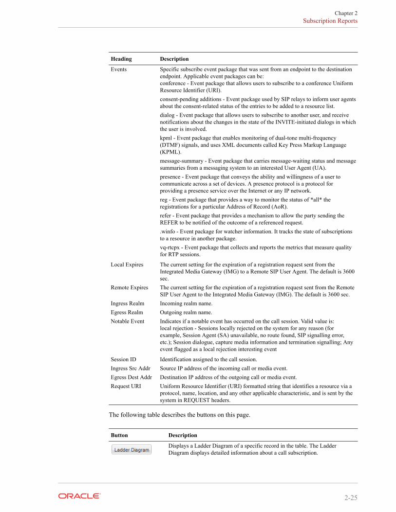
Heading Description
Events Specific subscribe event package that was sent from an endpoint to the destinationendpoint. Applicable event packages can be:conference - Event package that allows users to subscribe to a conference UniformResource Identifier (URI).consent-pending additions - Event package used by SIP relays to inform user agentsabout the consent-related status of the entries to be added to a resource list.dialog - Event package that allows users to subscribe to another user, and receivenotifications about the changes in the state of the INVITE-initiated dialogs in whichthe user is involved.kpml - Event package that enables monitoring of dual-tone multi-frequency(DTMF) signals, and uses XML documents called Key Press Markup Language(KPML).message-summary - Event package that carries message-waiting status and messagesummaries from a messaging system to an interested User Agent (UA).presence - Event package that conveys the ability and willingness of a user tocommunicate across a set of devices. A presence protocol is a protocol forproviding a presence service over the Internet or any IP network.reg - Event package that provides a way to monitor the status of *all* theregistrations for a particular Address of Record (AoR).refer - Event package that provides a mechanism to allow the party sending theREFER to be notified of the outcome of a referenced request..winfo - Event package for watcher information. It tracks the state of subscriptionsto a resource in another package.vq-rtcpx - Event package that collects and reports the metrics that measure qualityfor RTP sessions.
Local Expires The current setting for the expiration of a registration request sent from theIntegrated Media Gateway (IMG) to a Remote SIP User Agent. The default is 3600sec.
Remote Expires The current setting for the expiration of a registration request sent from the RemoteSIP User Agent to the Integrated Media Gateway (IMG). The default is 3600 sec.
Ingress Realm Incoming realm name.Egress Realm Outgoing realm name.Notable Event Indicates if a notable event has occurred on the call session. Valid value is:
local rejection - Sessions locally rejected on the system for any reason (forexample, Session Agent (SA) unavailable, no route found, SIP signalling error,etc.); Session dialogue, capture media information and termination signalling; Anyevent flagged as a local rejection interesting event
Session ID Identification assigned to the call session.Ingress Src Addr Source IP address of the incoming call or media event.Egress Dest Addr Destination IP address of the outgoing call or media event.Request URI Uniform Resource Identifier (URI) formatted string that identifies a resource via a
protocol, name, location, and any other applicable characteristic, and is sent by thesystem in REQUEST headers.
The following table describes the buttons on this page.
Button Description
Displays a Ladder Diagram of a specific record in the table. The LadderDiagram displays detailed information about a call subscription.
Chapter 2Subscription Reports
2-25

Button Description
Exports the subscription information associated with the selected record, to afile in text format on the local machine.Exports all logged subscription records to a file in text format on the localmachine.Performs a refresh of the page and updates it with the latest data.
Allows you to specify parameters for performing a search for specificsubscription records within the current report.Displays all of the subscription records in the Subscriptions Report.
To display a Subscriptions Report:
1. After logging into the Web-based GUI, click Subscriptions in the left column. Thesubscriptions summary report displays.
2. Use the buttons on the bottom of the page to view information about the records in thisreport. For information about Refresh, see Refresh. For information about the LadderDiagram, see Ladder Diagram. For information about exporting information, see ExportingInformation to a Text File.
Notable Event ReportsThe Notable Events Report contains all logged sessions that have a notable event associatedwith the session on the Oracle Communications Session Border Controller. The data thatdisplays in this table is dependent on the filters set via the ACLI on the Oracle CommunicationsSession Border Controller.
Note:
For setting filters to capture applicable data, see Filters to Configure sessions that havea nota.
The columns that display on the Notable Events Report page are dependent on the columns youselected in the procedure, Customizing the Page Display.
The following table describes the columns on this page.
Heading Description
Start Time Timestamp of the first SIP message in the call session.
Chapter 2Notable Event Reports
2-26

Heading Description
State Status of the call or media event session. Valid values are:INITIAL Session for which an INVITE or SUBSCRIBE was forwarded.EARLY Session received the first provisional response (1xx other than 100).ESTABLISHED Session for which a success (2xx) response was received.TERMINATED Session that has ended by receiving or sending a BYE for an“Established” session or forwarding an error response for an “Initial” or Earlysession. The session remains in the terminated state until all the resources for thesession are freed up.FAILED Session that has failed due to a 4xx or 5xx error code.
Call ID Identification of the call source. Includes the phone number and source IP address.Request URI Uniform Resource Identifier (URI) formatted string that identifies a resource via a
protocol, name, location, and any other applicable characteristic, and is sent by thesystem in REQUEST headers.
To URI URI formatted string that identifies the call destination information.From URI URI formatted string that identifies the call source information.Events Specific subscribe event package that was sent from an endpoint to the destination
endpoint. Applicable event packages can be:conference - Event package that allows users to subscribe to a conference UniformResource Identifier (URI).consent-pending additions - Event package used by SIP relays to inform user agentsabout the consent-related status of the entries to be added to a resource list.dialog - Event package that allows users to subscribe to another user, and receivenotifications about the changes in the state of the INVITE-initiated dialogs in whichthe user is involved.kpml - Event package that enables monitoring of dual-tone multi-frequency(DTMF) signals, and uses XML documents called Key Press Markup Language(KPML).message-summary - Event package that carries message-waiting status and messagesummaries from a messaging system to an interested User Agent (UA).presence - Event package that conveys the ability and willingness of a user tocommunicate across a set of devices. A presence protocol is a protocol forproviding a presence service over the Internet or any IP network.reg - Event package that provides a way to monitor the status of *all* theregistrations for a particular Address of Record (AoR).refer - Event package that provides a mechanism to allow the party sending theREFER to be notified of the outcome of a referenced request..winfo - Event package for watcher information. It tracks the state of subscriptionsto a resource in another package.vq-rtcpx - Event package that collects and reports the metrics that measure qualityfor RTP sessions.
Ingress Realm Incoming realm name.Egress Realm Outgoing realm name.Notable Event Indicates if an interesting event has occurred on the call session. Valid values are:
short session - A session is viewed as a "short session" if the length of time, inseconds, is equal to or below the short-session-duration value configured at the pathTerminal->session-router->session-router-config->short-session-duration in theACLI.local rejection - Sessions that are locally rejected at the Oracle CommunicationsSession Border Controller for any reason (for example, Session Agent (SA)unavailable, no route found, SIP signalling error, etc.).
Session ID Identification assigned to the call session.
Chapter 2Notable Event Reports
2-27

Heading Description
Ingress Src Addr Source IP address of the incoming call or media event.Egress Dest Addr Destination IP address of the outgoing call or media event.
The following table describes the buttons on this page.
Button Description
Displays a Ladder Diagram of a specific record in the table. The LadderDiagram displays detailed information about a notable event.Exports the notable event information associated with the selected record, to afile in text format on the local machine.Exports all logged notable event records to a file in text format on the localmachine.Performs a refresh of the page and updates it with the latest data.
Allows you to specify parameters for performing a search for specific notableevent records within the current report.Displays all of the notable event records in the Notable Events Report.
To display a Notable Events Report:
1. After logging into the Web-based GUI, click Notable Events in the left column. Thenotable events summary report displays.
2. Use the buttons on the bottom of the page to view information about the records in thisreport. For information about Refresh, see Refresh. For information about the LadderDiagram, see Ladder Diagram. For information about exporting information, see ExportingInformation to a Text File.
Chapter 2Notable Event Reports
2-28