calculation number - georgiapower.com · plant scherer ash pond and retention pond slope stability...
TRANSCRIPT
Plant Scherer Ash Pond and Retention Pond Slope Stability
Rev. 0
1
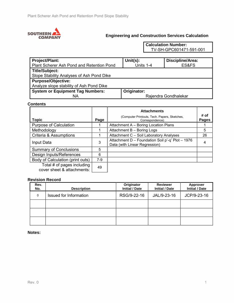
Calculation Number: TV-SH-GPC601471-591-001
Project/Plant: Plant Scherer Ash Pond and Retention Pond
Unit(s): Units 1-4
Discipline/Area: ES&FS
Title/Subject: Slope Stability Analyses of Ash Pond Dike Purpose/Objective: Analyze slope stability of Ash Pond Dike System or Equipment Tag Numbers:
NA Originator:
Rajendra Gondhalekar
Topic Page
Attachments
(Computer Printouts, Tech. Papers, Sketches, Correspondence)
# of Pages
Purpose of Calculation 1 Attachment A – Boring Location Plans 1 Methodology 1 Attachment B – Boring Logs 5 Criteria & Assumptions 1 Attachment C – Soil Laboratory Analyses 26
Input Data 3 Attachment D – Foundation Soil p’-q’ Plot – 1976 Data (with Linear Regression) 4
Summary of Conclusions 5 Design Inputs/References 6 Body of Calculation (print outs) 7-9
Total # of pages including cover sheet & attachments: 49
Rev. No. Description
Originator Initial / Date
Reviewer Initial / Date
Approver Initial / Date
0 Issued for Information RSG/9-22-16 JAL/9-23-16 JCP/9-23-16
Notes:
Contents
Revision Record
Engineering and Construction Services Calculation
Plant Scherer Ash Pond and Retention Pond Slope Stability
Rev. 0
2
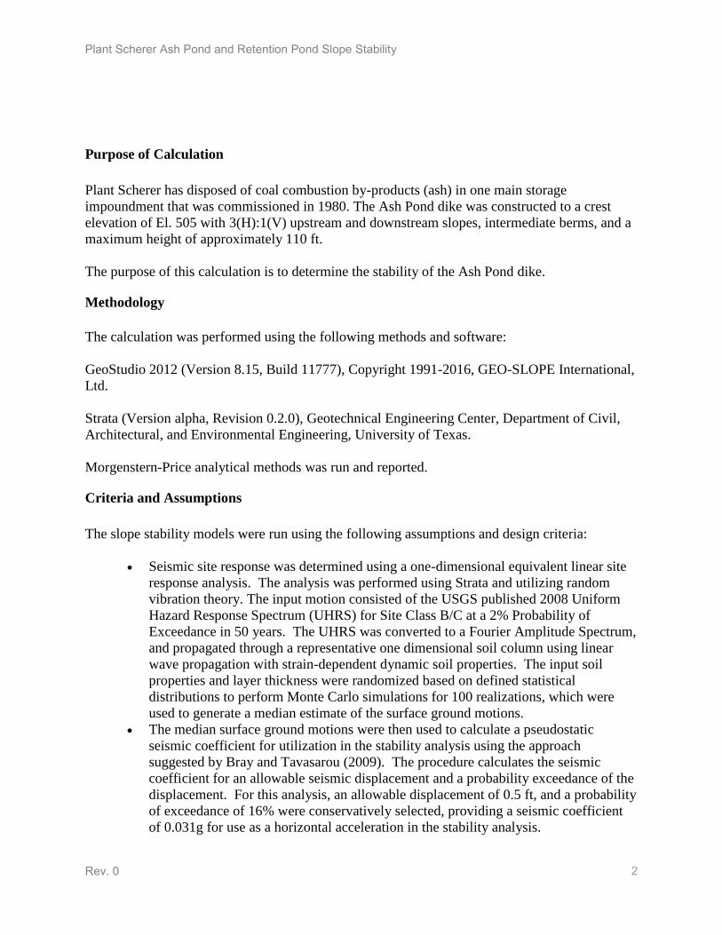
Purpose of Calculation
Plant Scherer has disposed of coal combustion by-products (ash) in one main storage
impoundment that was commissioned in 1980. The Ash Pond dike was constructed to a crest
elevation of El. 505 with 3(H):1(V) upstream and downstream slopes, intermediate berms, and a
maximum height of approximately 110 ft.
The purpose of this calculation is to determine the stability of the Ash Pond dike.
Methodology
The calculation was performed using the following methods and software:
GeoStudio 2012 (Version 8.15, Build 11777), Copyright 1991-2016, GEO-SLOPE International,
Ltd.
Strata (Version alpha, Revision 0.2.0), Geotechnical Engineering Center, Department of Civil,
Architectural, and Environmental Engineering, University of Texas.
Morgenstern-Price analytical methods was run and reported.
Criteria and Assumptions
The slope stability models were run using the following assumptions and design criteria:
Seismic site response was determined using a one-dimensional equivalent linear site
response analysis. The analysis was performed using Strata and utilizing random
vibration theory. The input motion consisted of the USGS published 2008 Uniform
Hazard Response Spectrum (UHRS) for Site Class B/C at a 2% Probability of
Exceedance in 50 years. The UHRS was converted to a Fourier Amplitude Spectrum,
and propagated through a representative one dimensional soil column using linear
wave propagation with strain-dependent dynamic soil properties. The input soil
properties and layer thickness were randomized based on defined statistical
distributions to perform Monte Carlo simulations for 100 realizations, which were
used to generate a median estimate of the surface ground motions.
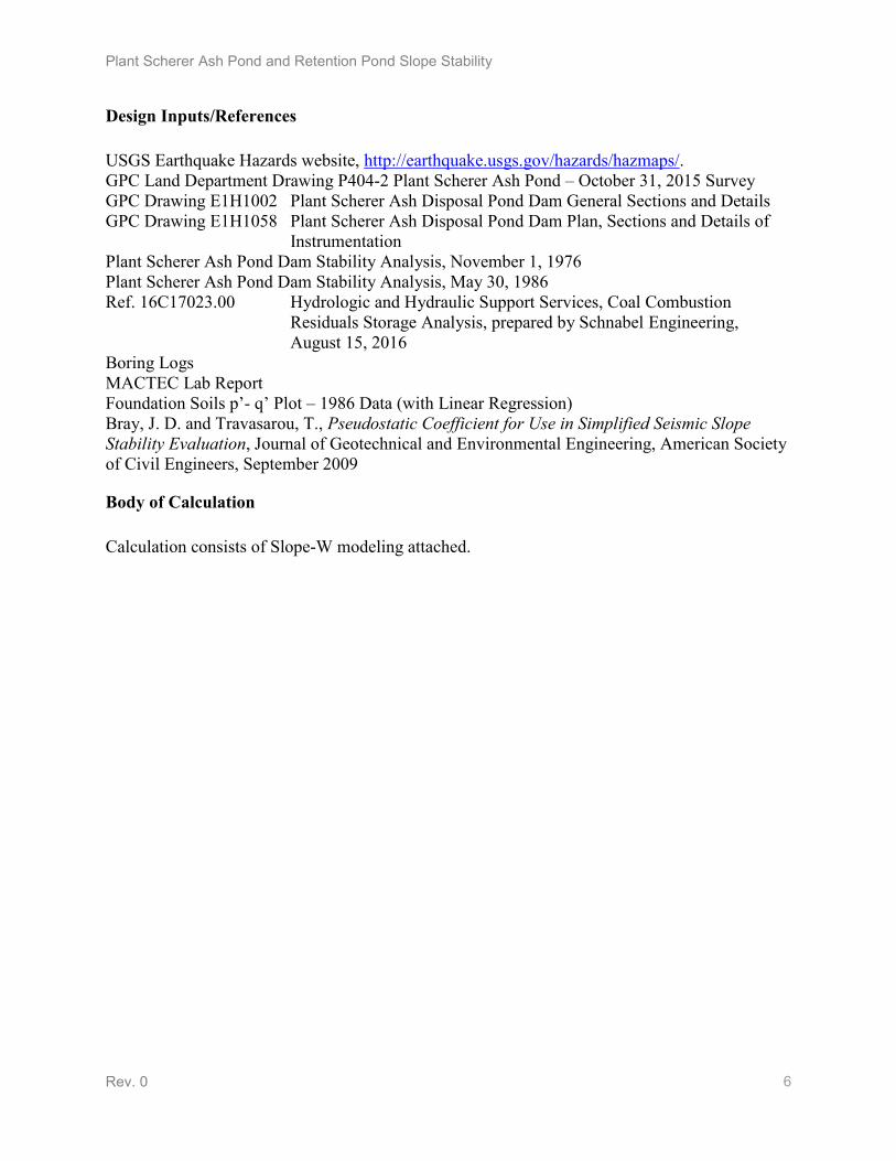
The median surface ground motions were then used to calculate a pseudostatic
seismic coefficient for utilization in the stability analysis using the approach
suggested by Bray and Tavasarou (2009). The procedure calculates the seismic
coefficient for an allowable seismic displacement and a probability exceedance of the
displacement. For this analysis, an allowable displacement of 0.5 ft, and a probability
of exceedance of 16% were conservatively selected, providing a seismic coefficient
of 0.031g for use as a horizontal acceleration in the stability analysis.
Plant Scherer Ash Pond and Retention Pond Slope Stability
Rev. 0
3
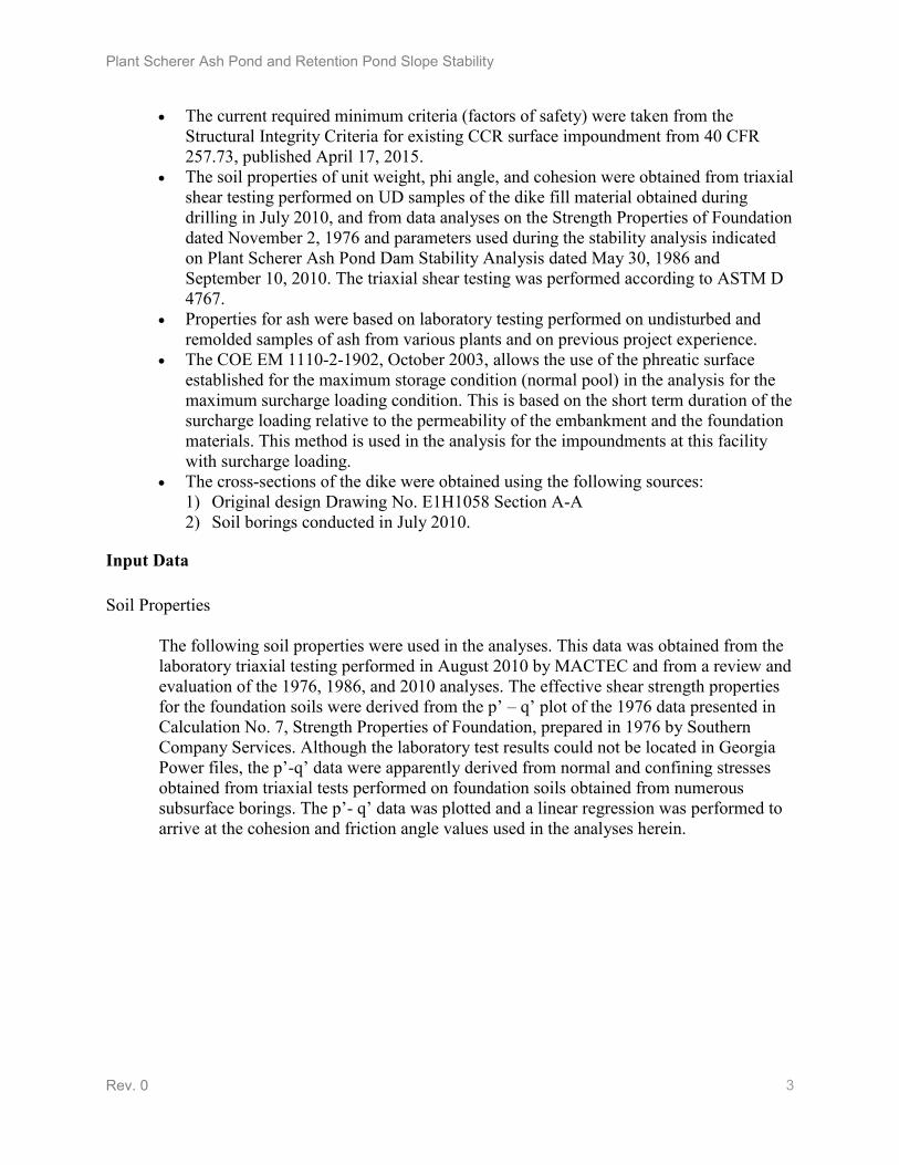
The current required minimum criteria (factors of safety) were taken from the
Structural Integrity Criteria for existing CCR surface impoundment from 40 CFR
257.73, published April 17, 2015.
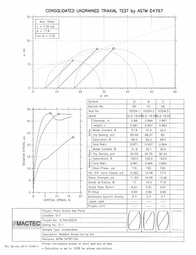
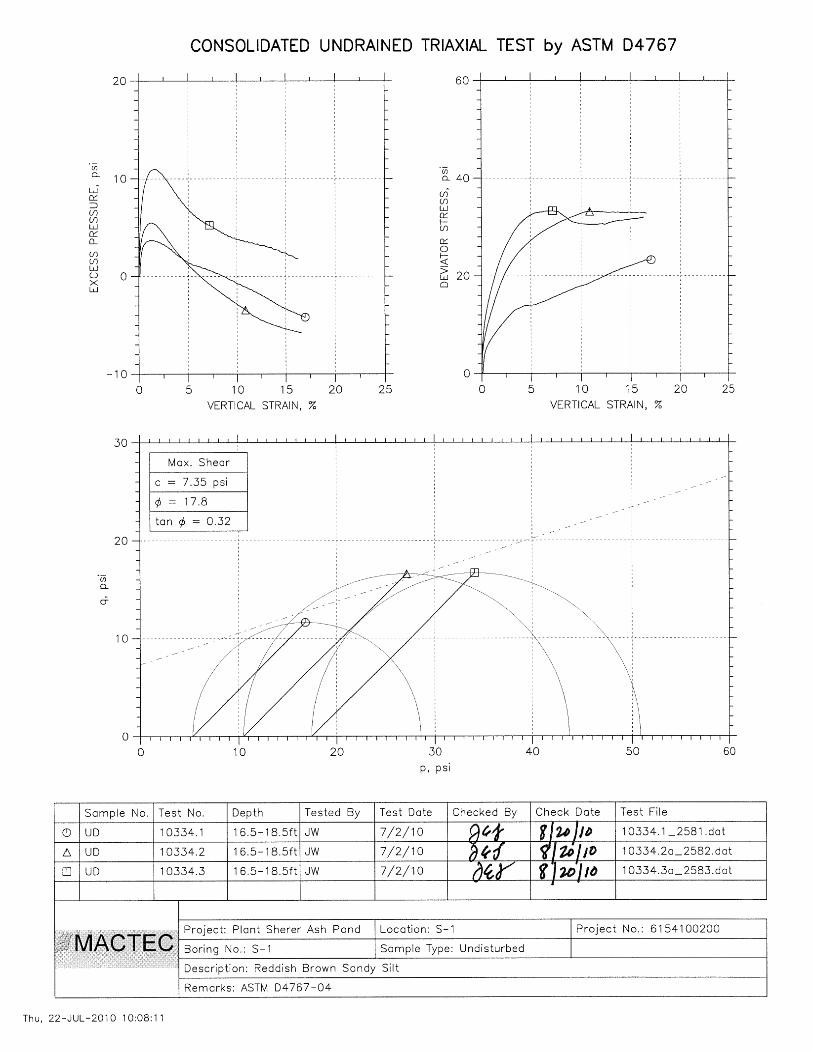
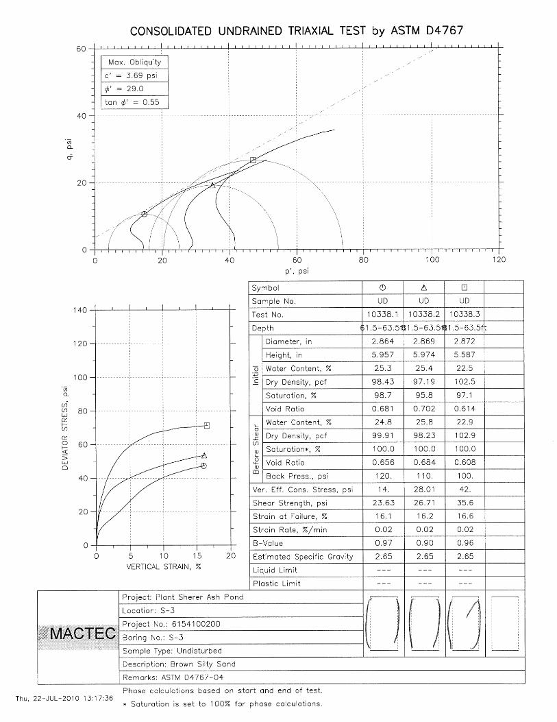
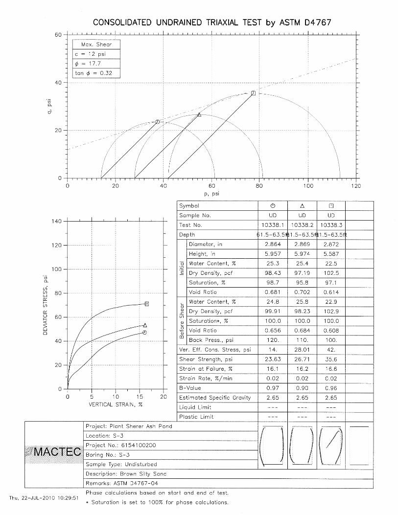
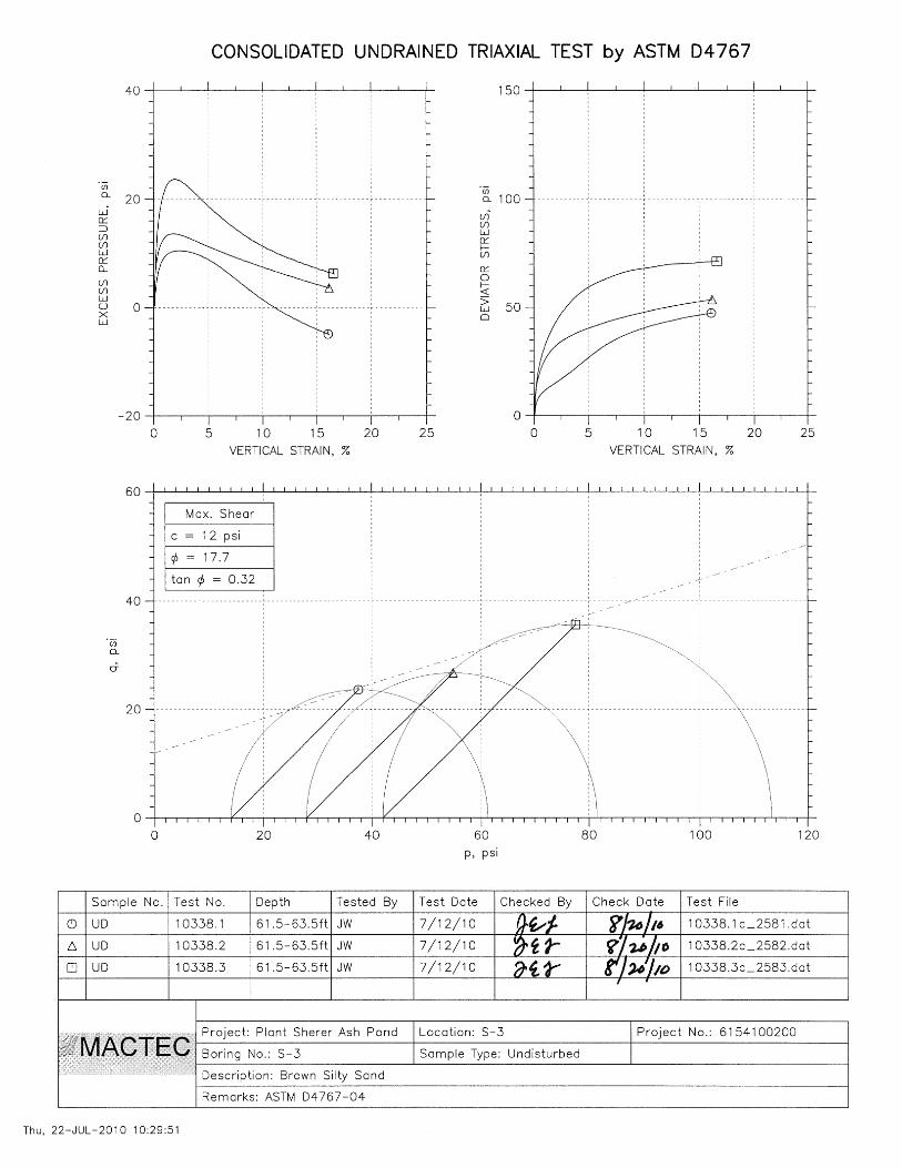
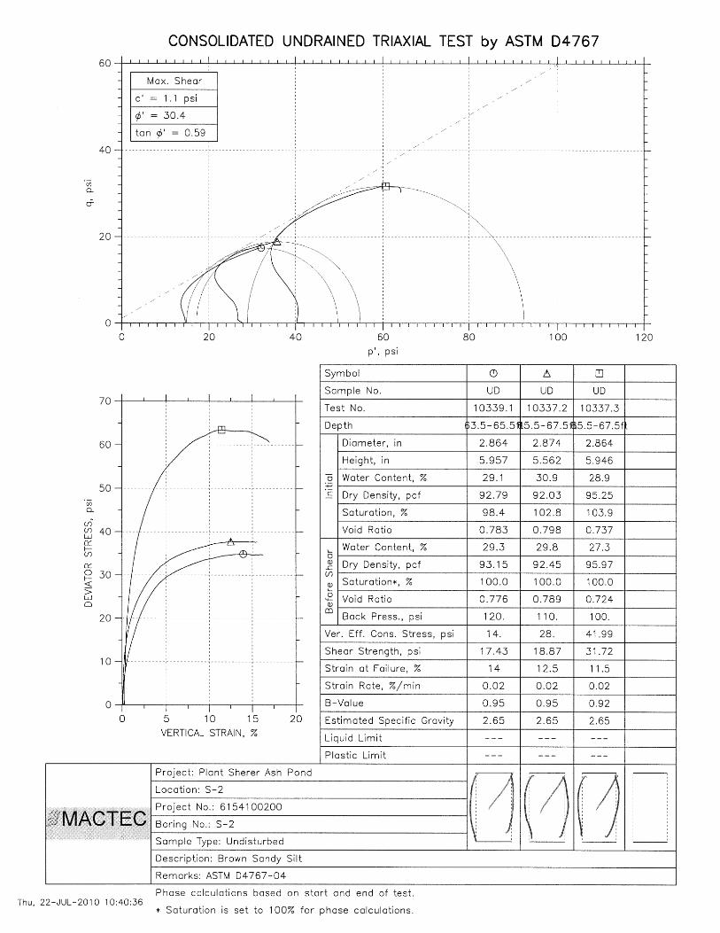
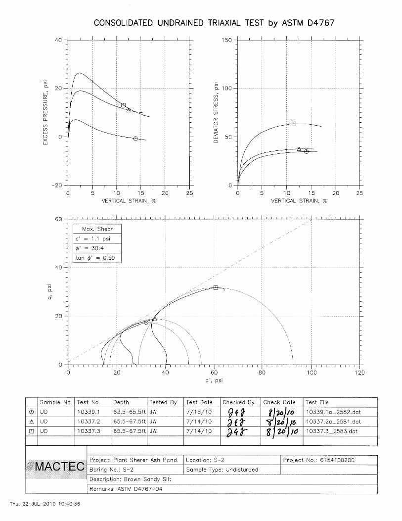
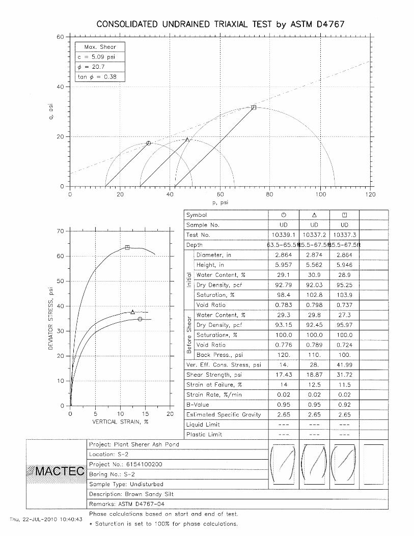
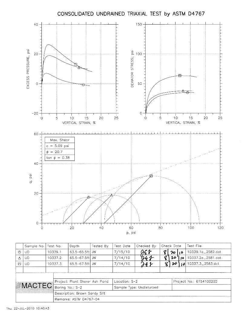
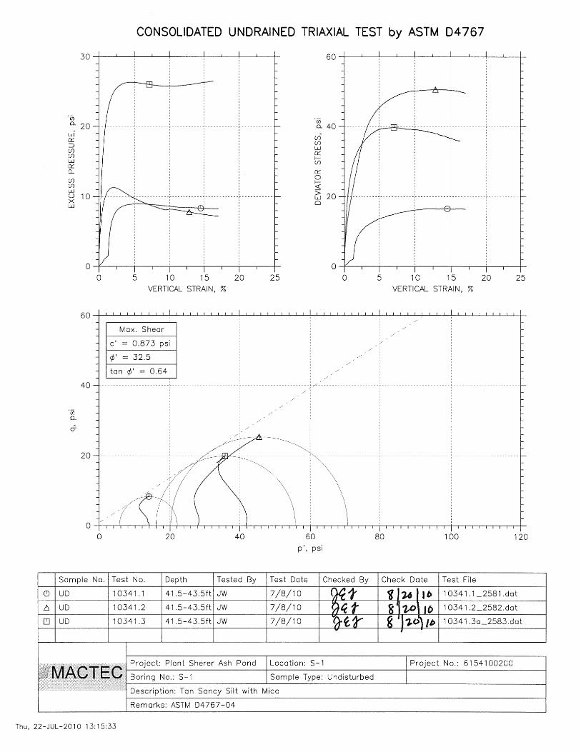
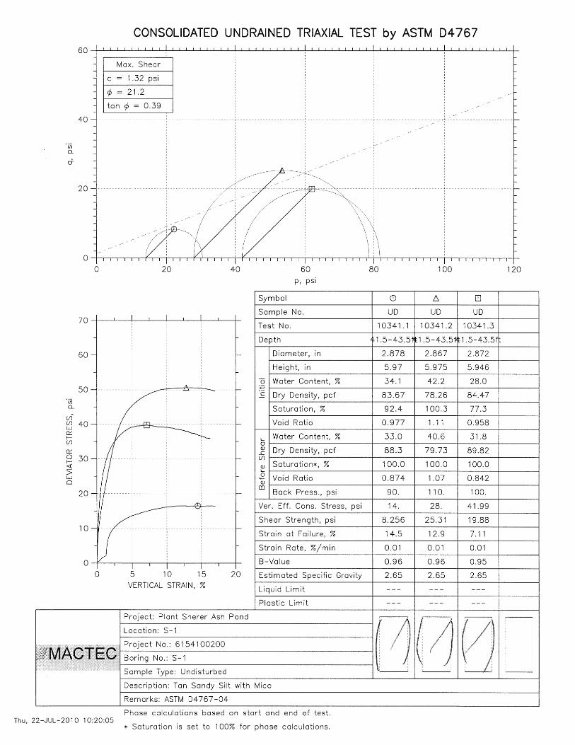
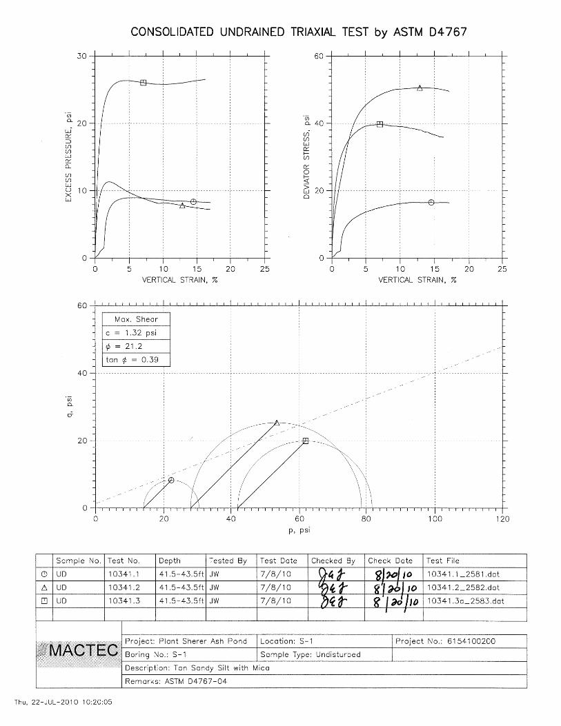
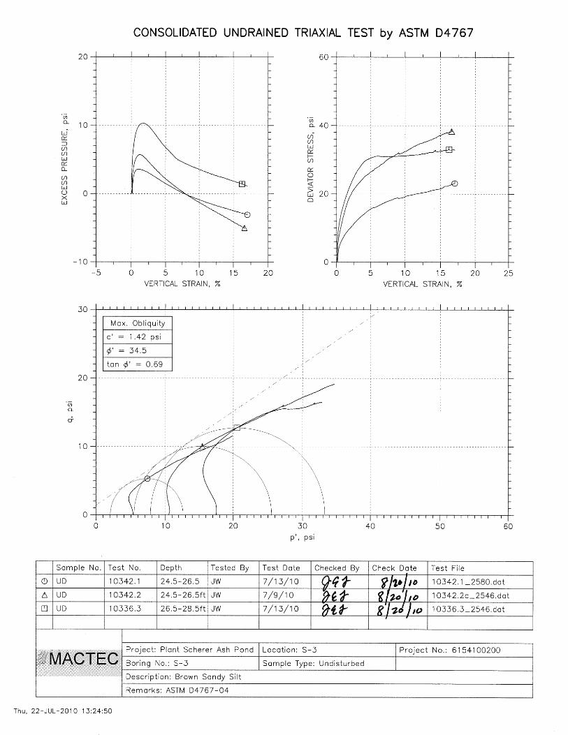
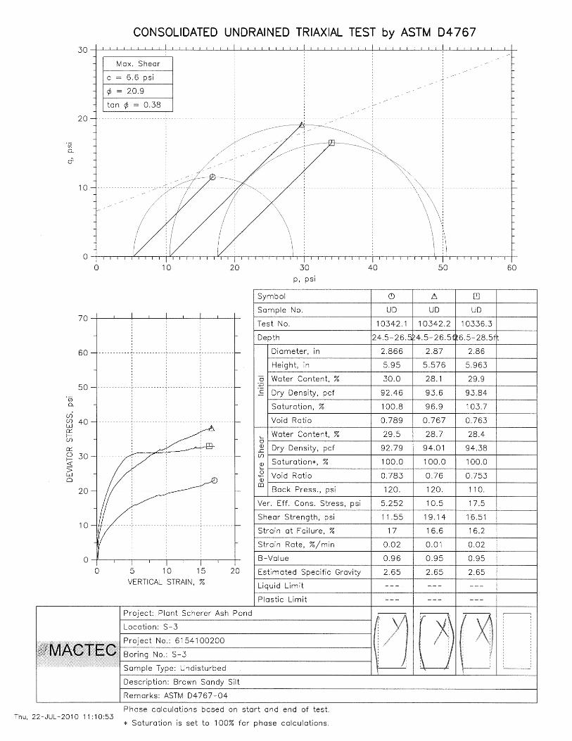
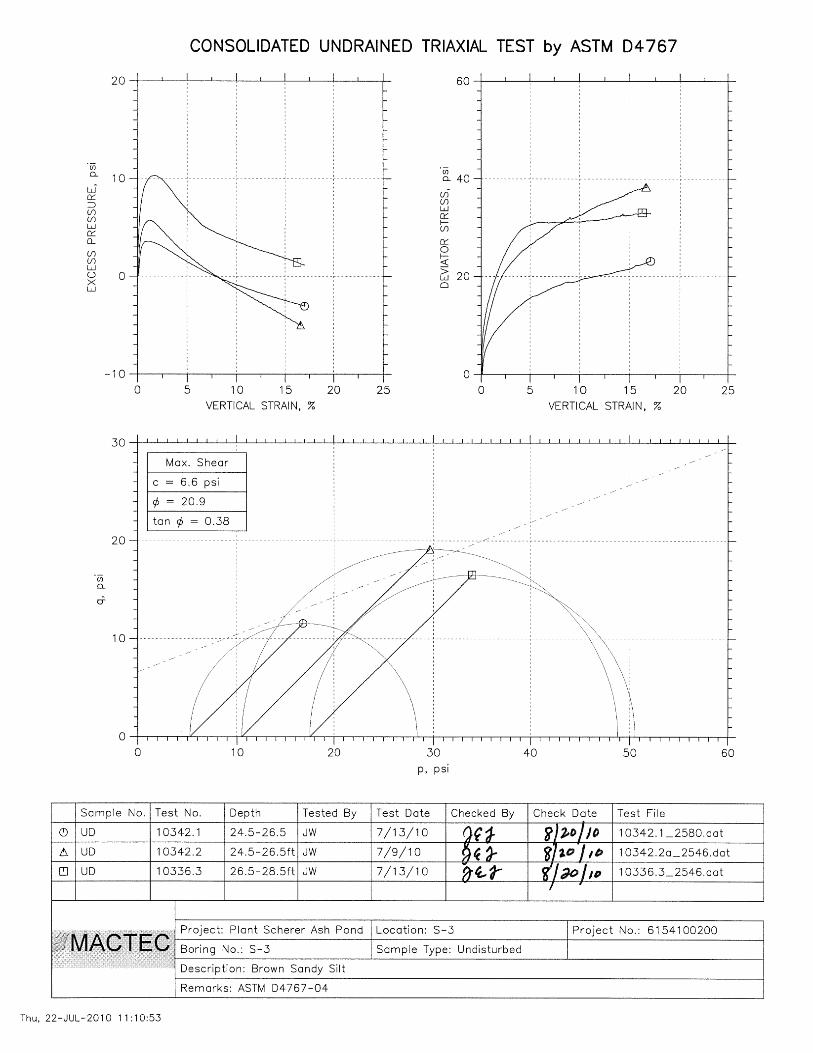
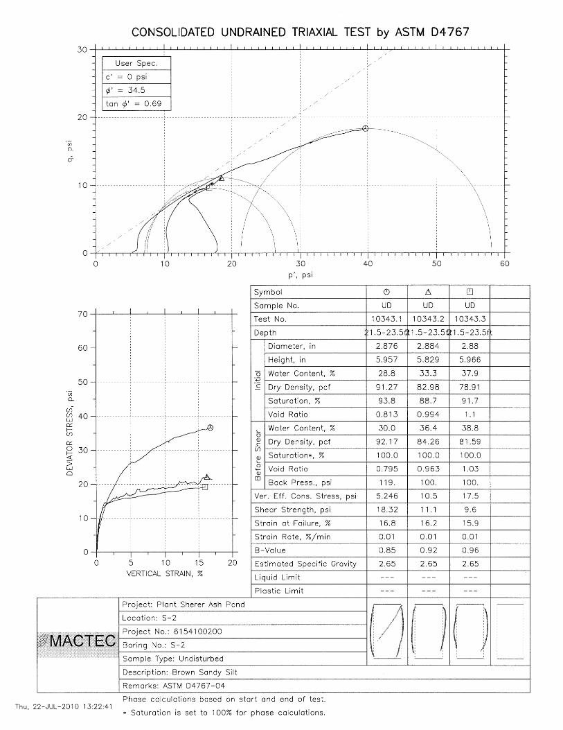
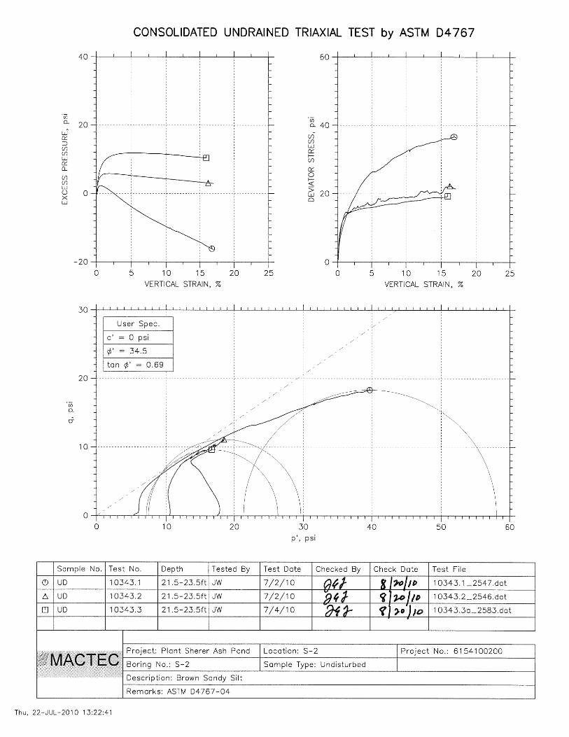
The soil properties of unit weight, phi angle, and cohesion were obtained from triaxial
shear testing performed on UD samples of the dike fill material obtained during
drilling in July 2010, and from data analyses on the Strength Properties of Foundation
dated November 2, 1976 and parameters used during the stability analysis indicated
on Plant Scherer Ash Pond Dam Stability Analysis dated May 30, 1986 and
September 10, 2010. The triaxial shear testing was performed according to ASTM D
4767.
Properties for ash were based on laboratory testing performed on undisturbed and
remolded samples of ash from various plants and on previous project experience.
The COE EM 1110-2-1902, October 2003, allows the use of the phreatic surface
established for the maximum storage condition (normal pool) in the analysis for the
maximum surcharge loading condition. This is based on the short term duration of the
surcharge loading relative to the permeability of the embankment and the foundation
materials. This method is used in the analysis for the impoundments at this facility
with surcharge loading.
The cross-sections of the dike were obtained using the following sources:
1) Original design Drawing No. E1H1058 Section A-A
2) Soil borings conducted in July 2010.
Input Data
Soil Properties
The following soil properties were used in the analyses. This data was obtained from the
laboratory triaxial testing performed in August 2010 by MACTEC and from a review and
evaluation of the 1976, 1986, and 2010 analyses. The effective shear strength properties
for the foundation soils were derived from the p’ – q’ plot of the 1976 data presented in
Calculation No. 7, Strength Properties of Foundation, prepared in 1976 by Southern
Company Services. Although the laboratory test results could not be located in Georgia
Power files, the p’-q’ data were apparently derived from normal and confining stresses
obtained from triaxial tests performed on foundation soils obtained from numerous
subsurface borings. The p’- q’ data was plotted and a linear regression was performed to
arrive at the cohesion and friction angle values used in the analyses herein.

Plant Scherer Ash Pond and Retention Pond Slope Stability
Rev. 0
4
Soil
Materials
Moist
Unit
Weight
(pcf)
Effective Stress
Parameters Total Stress Parameters
Data Source Internal
Friction
Angle
Cohesion
(psf)
Internal
Friction
Angle
Cohesion
(psf)
Embankment
Fill 120 33 63 20 700
Triaxial Test
Dated July 2010
Foundation
Soil 108 24 302 20 500
Analysis Dated
May 1986
Rock Bolster 110 42 0 42 0 Analysis Dated
September 2010
Consolidated
Ash 105 20 0 -- --
Analysis Dated
September 2010
Sluiced Ash 80 10 0 10 0 Analysis Dated
September 2010
Hydrologic Considerations
The following hydraulic information, based on the calculation package Schnabel Reference
16C17023.00, Hydrologic and Hydraulic Support Services, Coal Combustion Residuals Storage
Analysis, dated August 15, 2016, prepared by Schnabel Engineering., was used in the analyses.
This calculation states that the Ash Pond is capable of handling the PMP with a maximum
surcharge pool elevation of 501.6.
Based on Georgia Power’s (GP) Land Department Drawing P404-2, 20150465 Plant Scherer
Ash Pond Aerial Topo and Bathymetric Survey, the top elevation of the ash along the east dike
of the Ash Pond is approximately El. 497 as of October 31, 2015. This ash load has been be
incorporated into the ash pond analyses for current conditions. An ash/final cover (closure)
elevation for the Ash Pond of Elev. 505 is used for a full ash load case.
Loading Condition
The stability of the Ash Pond dike was evaluated under the following loading conditions:
Long-term Maximum Storage Pool (Static) with maximum ash elevation in the pond
Maximum Surcharge Pool (Static) with current ash elevation in the pond.
Seismic with maximum ash elevation in the pond.
Method of Analyses
The calculations were performed using 2012 (Version 8.15, Build 11777), Copyright 1991-2016,
GEO-SLOPE International, Ltd. The search method for minimum factors of safety (FOS) was
the Entry and Exit Method. This method can provide a comprehensive search for the minimum
FOS provided that the entry and exit limits are selected appropriately. Once the critical failure
Plant Scherer Ash Pond and Retention Pond Slope Stability
Rev. 0
5
surface had been identified by the Entry and Exit method, that surface was further optimized to
allow for noncircular failure surfaces.
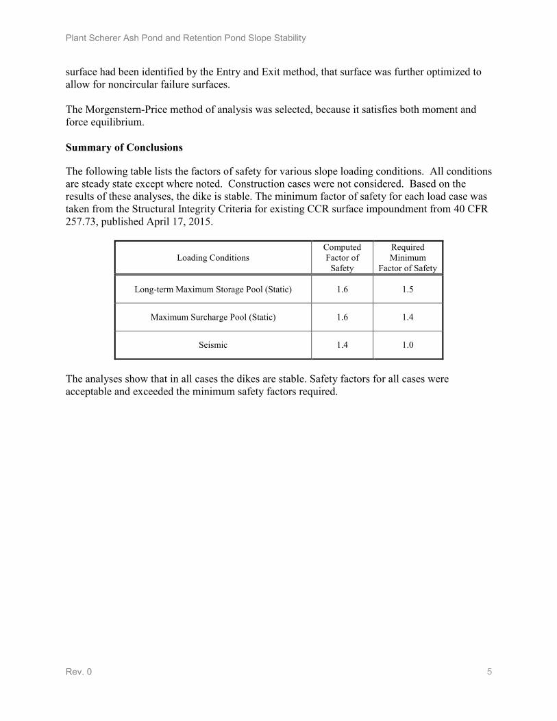
The Morgenstern-Price method of analysis was selected, because it satisfies both moment and
force equilibrium.
Summary of Conclusions
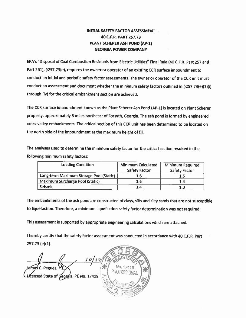
The following table lists the factors of safety for various slope loading conditions. All conditions
are steady state except where noted. Construction cases were not considered. Based on the
results of these analyses, the dike is stable. The minimum factor of safety for each load case was
taken from the Structural Integrity Criteria for existing CCR surface impoundment from 40 CFR
257.73, published April 17, 2015.
Loading Conditions
Computed
Factor of
Safety
Required
Minimum
Factor of Safety
Long-term Maximum Storage Pool (Static) 1.6 1.5
Maximum Surcharge Pool (Static) 1.6 1.4
Seismic 1.4 1.0
The analyses show that in all cases the dikes are stable. Safety factors for all cases were
acceptable and exceeded the minimum safety factors required.
Plant Scherer Ash Pond and Retention Pond Slope Stability
Rev. 0
6
Design Inputs/References
USGS Earthquake Hazards website, http://earthquake.usgs.gov/hazards/hazmaps/.
GPC Land Department Drawing P404-2 Plant Scherer Ash Pond – October 31, 2015 Survey
GPC Drawing E1H1002 Plant Scherer Ash Disposal Pond Dam General Sections and Details
GPC Drawing E1H1058 Plant Scherer Ash Disposal Pond Dam Plan, Sections and Details of
Instrumentation
Plant Scherer Ash Pond Dam Stability Analysis, November 1, 1976
Plant Scherer Ash Pond Dam Stability Analysis, May 30, 1986
Ref. 16C17023.00 Hydrologic and Hydraulic Support Services, Coal Combustion
Residuals Storage Analysis, prepared by Schnabel Engineering,
August 15, 2016
Boring Logs
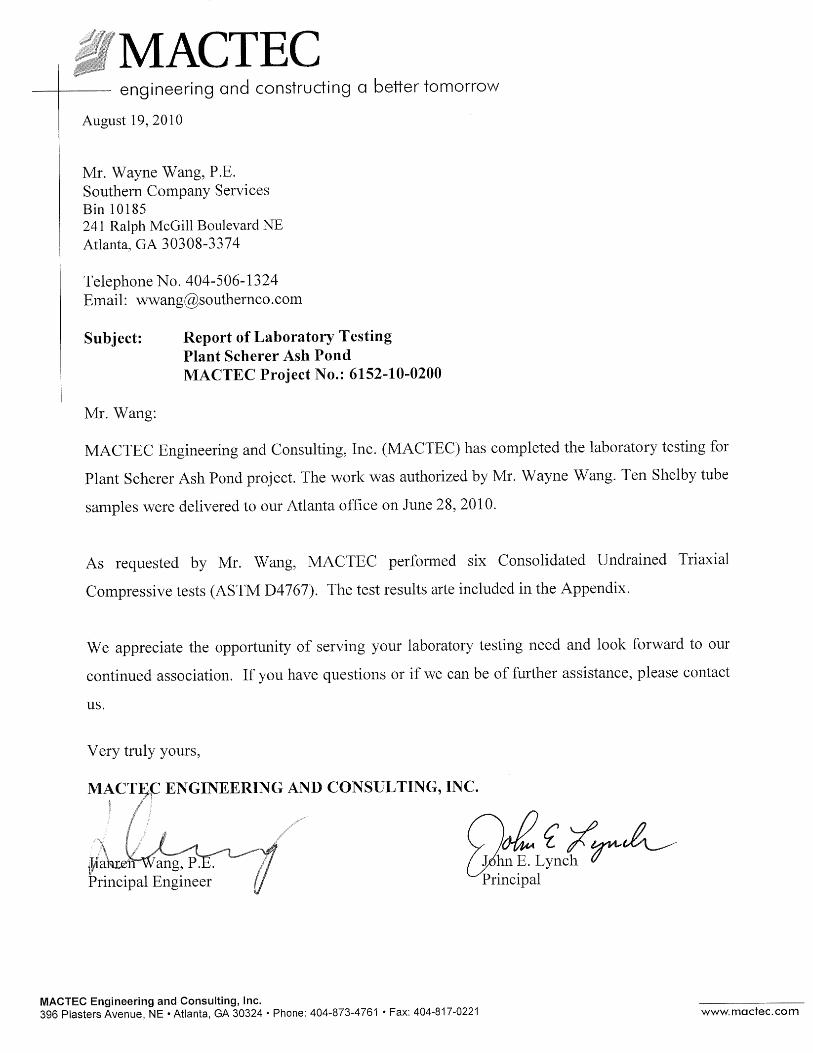
MACTEC Lab Report
Foundation Soils p’- q’ Plot – 1986 Data (with Linear Regression)
Bray, J. D. and Travasarou, T., Pseudostatic Coefficient for Use in Simplified Seismic Slope
Stability Evaluation, Journal of Geotechnical and Environmental Engineering, American Society
of Civil Engineers, September 2009
Body of Calculation
Calculation consists of Slope-W modeling attached.

1.58
Rock Bolster
Foundation Soil
Ash
Fill
El. 505
El.457
El. 410
Method: Morgenstern-Price
Plant Scherer Ash Pond Dike Stability Analysis (Section A-A)
Downstream Steady State w/ Full Loading Ash
Optimization of slip surface location
El. 496
Distance
0 100 200 300 400 500 600 700 800 900 1,000 1,100 1,200
Ele
vatio
n
300
350
400
450
500
550
1.6
Rock Bolster
Foundation Soil
Ash Fill
El. 505
El.457
El. 410
Method: Morgenstern-Price
Plant Scherer Ash Pond Dike Stability Analysis (Section A-A)
Downstream Max. Surcharge Pool
Optimization of slip surface location
El. 502.3
Distance
0 100 200 300 400 500 600 700 800 900 1,000 1,100 1,200
Ele
vatio
n
300
350
400
450
500
550
1.40
Rock Bolster
Foundation Soil
Ash
Fill
El. 505
El.457
El. 410
Method: Morgenstern-Price
Plant Scherer Ash Pond Dike Stability Analysis (Section A-A)
Downstream Seismic w/ Full Loading Ash (0.5 ft disp.)
Optimization of slip surface location
El. 496
Distance
0 100 200 300 400 500 600 700 800 900 1,000 1,100 1,200
Ele
vatio
n
300
350
400
450
500
550

Plant Scherer Ash Pond and Retention Pond Slope Stability
Rev. 0
10
Attachment A
Figures - Boring Location Plans


Plant Scherer Ash Pond and Retention Pond Slope Stability
Rev. 0
12
Attachment B
Soil Logs
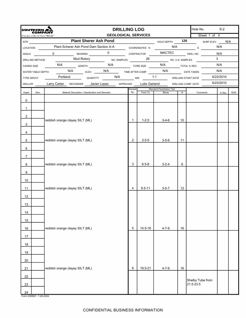
DRILLING LOG
GEOLOGICAL SERVICES
SITE
E
ANGLE CONTRACTOR
Depth Elev. % Rec
0
1
2
3
4
5
6
7
8
9
10
11
12
13
14
15
16
17
18
19
20
21
22
23
24
reddish orange clayey SILT (ML)
reddish orange clayey SILT (ML)
reddish orange clayey SILT (ML)
reddish orange clayey SILT (ML)
reddish orange clayey SILT (ML)
1reddish orange clayey SILT (ML) 1-2.5 3-4-6 10
NBlowsStandard Penetration Test
From To
Form GS9901 7-26-2004
TYPE GROUT DRILLING START DATE
DRILLING COMP. DATEAPPROVEDRECORDER DRILLER Larry CarterSample
No.
WATER TABLE DEPTH ELEV. TIME AFTER COMP.
LENGTH CORE SIZEN/A
Javier Lopez Luke Garland
COORDINATES N
BEARING MACTEC
NO. SAMPLES
DATE TAKEN
N/APortland
0 0 LOCATION
S-2Hole No.
Plant Sherer Ash Pond
Plant Scherer Ash Pond Dam Section A-A
126
N/A
Sheet 1 of 5
6/23/2010
HOLE DEPTH SURF.ELEV.
DRILL NO.
3N/A
1:1
N/AN/A
26 DRILLING METHOD
CASING SIZE
Mud Rotory
N/A N/ANO. U.D. SAMPLES
N/A TOTAL % REC.
QUANTITY MIX
Material Description, Classification and Remarks Comments
2 3.5-5 113-5-6
3 6.5-8 3-2-4 6
4 9.5-11 123-5-7
5 14.5-16 4-7-9 16
6 19.5-21 164-7-9
21.5-23.5Shelby Tube from
N/A
6/22/2010
N/A N/A N/A
RQD
CONFIDENTIAL BUSINESS INFORMATION
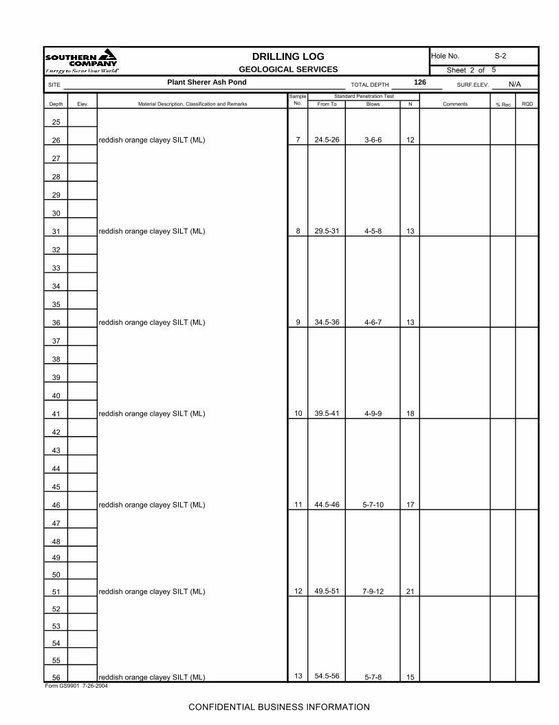
DRILLING LOG
GEOLOGICAL SERVICES
SITE TOTAL DEPTH SURF.ELEV.
Depth Elev. % Rec
25
26
27
28
29
30
31
32
33
34
35
36
37
38
39
40
41
42
43
44
45
46
47
48
49
50
51
52
53
54
55
56 reddish orange clayey SILT (ML)
Sheet 2 of
reddish orange clayey SILT (ML)
reddish orange clayey SILT (ML)
reddish orange clayey SILT (ML)
reddish orange clayey SILT (ML)
reddish orange clayey SILT (ML)
reddish orange clayey SILT (ML)
Hole No. S-2
5
15
21
54.5-5613
49.5-51
11 44.5-46 5-7-10 17
4-9-910 39.5-41 18
9 34.5-36 4-6-7 13
8 29.5-31 134-5-8
24.5-26 3-6-6 12
5-7-8Form GS9901 7-26-2004
12 7-9-12
Plant Sherer Ash Pond 126 N/A
Material Description, Classification and Remarks CommentsSample
No.Standard Penetration Test
From To Blows N RQD
7
CONFIDENTIAL BUSINESS INFORMATION
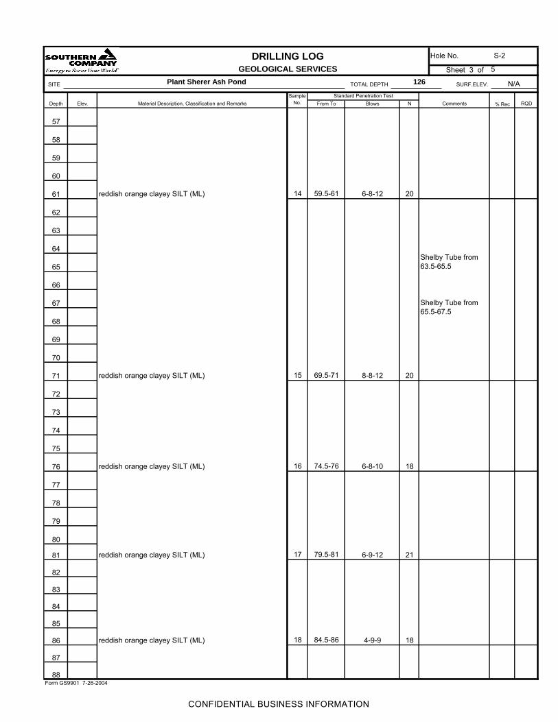
DRILLING LOG
GEOLOGICAL SERVICES
SITE TOTAL DEPTH SURF.ELEV.
Depth Elev. % Rec
57
58
59
60
61
62
63
64
65
66
67
68
69
70
71
72
73
74
75
76
77
78
79
80
81
82
83
84
85
86
87
88
5
reddish orange clayey SILT (ML)
reddish orange clayey SILT (ML)
reddish orange clayey SILT (ML)
reddish orange clayey SILT (ML)
reddish orange clayey SILT (ML)
17 79.5-81 6-9-12 21
14 59.5-61 6-8-12 20
Hole No. S-2
Sheet 3 of
16 74.5-76 6-8-10 18
15 69.5-71 8-8-12 20
Shelby Tube from
Shelby Tube from
Material Description, Classification and Remarks CommentsSample
No.Standard Penetration Test
From To RQD
Plant Sherer Ash Pond 126 N/A
Blows N
63.5-65.5
65.5-67.5
18 84.5-86 4-9-9 18
Form GS9901 7-26-2004
CONFIDENTIAL BUSINESS INFORMATION
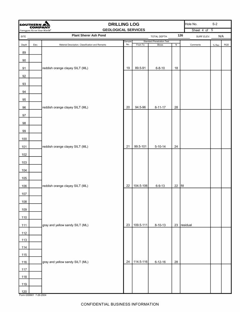
DRILLING LOG
GEOLOGICAL SERVICES
SITE TOTAL DEPTH SURF.ELEV.
Depth Elev. % Rec
89
90
91
92
93
94
95
96
97
98
99
100
101
102
103
104
105
106
107
108
109
110
111
112
113
114
115
116
117
118
119
120
5
gray and yellow sandy SILT (ML)
gray and yellow sandy SILT (ML)
reddish orange clayey SILT (ML)
reddish orange clayey SILT (ML)
reddish orange clayey SILT (ML)
reddish orange clayey SILT (ML)
23 109.5-111 8-10-13 23
22 104.5-106 6-9-13 22
20 94.5-96 8-11-17 28
N
19 89.5-91
Form GS9901 7-26-2004
24 114.5-116
Hole No. S-2
Sheet 4 of
286-12-16
6-8-10 18
Sample No.
Standard Penetration TestFrom To Blows
N/A
Material Description, Classification and Remarks Comments RQD
Plant Sherer Ash Pond 126
99.5-101 5-10-14 2421
fill
residual
CONFIDENTIAL BUSINESS INFORMATION

DRILLING LOG
GEOLOGICAL SERVICES
SITE TOTAL DEPTH SURF.ELEV.
Depth Elev. % Rec
121
122
123
124
125
126
127
128
129
130
131
132
133
134
135
136
137
138
139
140
141
142
143
144
145
146
147
148
149
150
151
152
N/A
Material Description, Classification and Remarks Comments RQD
Plant Sherer Ash Pond 126
Sample No.
Standard Penetration TestFrom To Blows
Hole No. S-2
119.5-121
Form GS9901 7-26-2004
N
13-17-20 3725
26 124.5-126 34-50/5 100+
gray and yellow sandy SILT (ML)
gray and white silty SAND (SM)Boring Completed @ 126'
Sheet 5 of 5

Plant Scherer Ash Pond and Retention Pond Slope Stability
Rev. 0
18
Attachment C
Soil Laboratory Analyses by MACTEC Engineering and Consulting.


Plant Scherer Ash Pond and Retention Pond Slope Stability
Rev. 0
45
Attachment D
Foundation soil p’ – q’ Plot
1976 Historic Data with Linear Regression

Plant Scherer Ash PondFoundation p' - q' plot - 1986 Data
y = 0.4467x + 0.3024
0
0.5
1
1.5
2
2.5
3
3.5
4
4.5
5
0 1 2 3 4 5 6 7 8 9
p = (S1+S3)/2 ksf
q =
(s1-s
3)/
2
ksf


