caiso workshop on reactive power requirements and ... · ge proprietary information caiso workshop...
TRANSCRIPT

GE Energy Consulting
GE Energy Consulting
GE Proprietary Information
CAISO Workshop on Reactive Power Requirements and Financial Compensation Jason MacDowell
Wind Turbines and Reactive Power Control
3
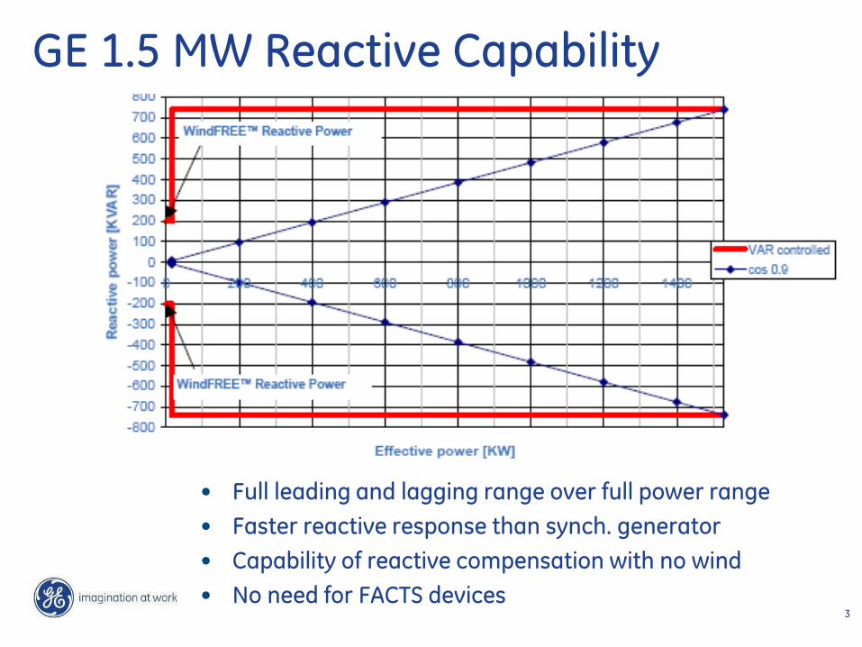
GE 1.5 MW Reactive Capability
• Full leading and lagging range over full power range
• Faster reactive response than synch. generator
• Capability of reactive compensation with no wind
• No need for FACTS devices
4
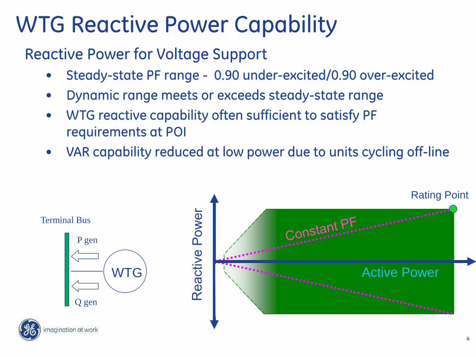
WTG Reactive Power Capability
Terminal Bus
P gen
Q gen
WTG
Reactive Power for Voltage Support
• Steady-state PF range - 0.90 under-excited/0.90 over-excited
• Dynamic range meets or exceeds steady-state range
• WTG reactive capability often sufficient to satisfy PF requirements at POI
• VAR capability reduced at low power due to units cycling off-line
Rating Point
Active Power

5
WindCONTROL
QWTG
PWTG
QWTG
PWTG
QWTG
PWTG
QWTG
PWTG
QWTG
PWTG
QWTG
PWTG
QL
QC
HV Bus
LV Bus
Reactive Compensation
(if required)
PWP
QWP
Substation
Point of Interconnection
(POI)
Reactive
Power
Controller
LTC
Plant Level Control System
• Coordinated turbine and plant supervisory control structure
• Voltage, VAR, & PF control
• PF requirements primarily met by WTG reactive capability, but augmented by mechanically switched shunt devices if necessary
• Combined plant response eliminates need for SVC, STATCOM, or other expensive equipment
• Integrated with substation SCADA
6 /
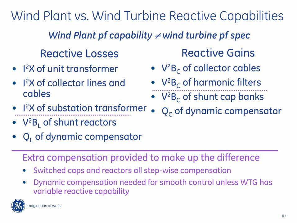
Wind Plant vs. Wind Turbine Reactive Capabilities
Wind Plant pf capability wind turbine pf spec
Reactive Losses
• I2X of unit transformer
• I2X of collector lines and cables
• I2X of substation transformer
• V2BL of shunt reactors
• QL of dynamic compensator
Reactive Gains
• V2BC of collector cables
• V2BC of harmonic filters
• V2BC of shunt cap banks
• QC of dynamic compensator
Extra compensation provided to make up the difference
• Switched caps and reactors all step-wise compensation
• Dynamic compensation needed for smooth control unless WTG has variable reactive capability

7 /
Voltage-Dependent Power Factor Spec From UK grid code
Assumes less reactive power injection when grid voltage is above nominal

8 /
System Strength
What is it?
• Usually measured in short circuit MVA
• MVAsc = kVb2/Xsc = 3½kVbkIsc
Why is it the single most important factor?
• Maximum short circuit (I.e. max kIsc or min Xsc) dictates breaker duties, many equipment ratings (later lecture)
• Minimum short circuit (I.e. min kIsc or max Xsc) dictates worst sensitivities, e.g. dV/dC, dV/dP, etc. (we’ll look at this some more below)
9 /
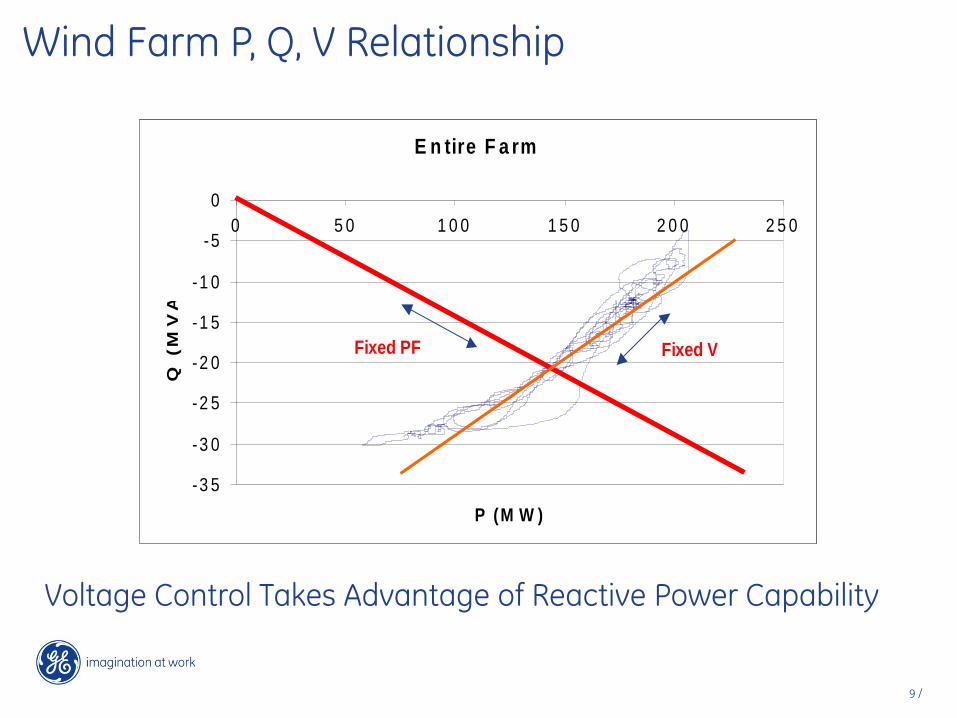
Wind Farm P, Q, V Relationship
E n tire F a rm
-3 5
-3 0
-2 5
-2 0
-1 5
-1 0
-5
0
0 5 0 1 0 0 1 5 0 2 0 0 2 5 0
P (M W )
Q (
MV
Ar)
Fixed PF Fixed V
E n tire F a rm
-3 5
-3 0
-2 5
-2 0
-1 5
-1 0
-5
0
0 5 0 1 0 0 1 5 0 2 0 0 2 5 0
P (M W )
Q (
MV
Ar)
Fixed PF Fixed V
Voltage Control Takes Advantage of Reactive Power Capability
10 /
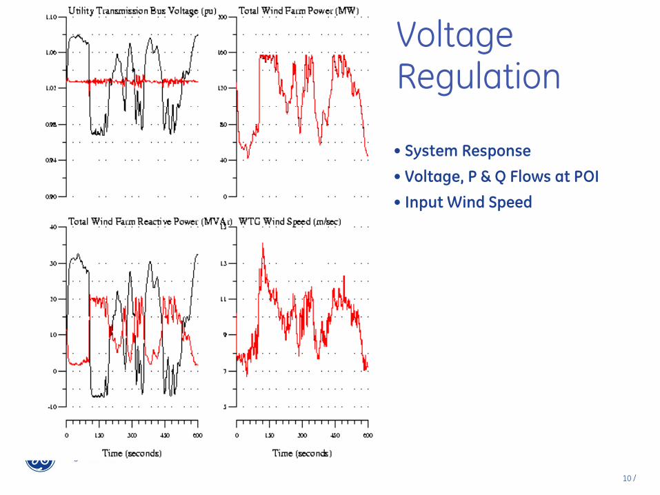
• System Response
• Voltage, P & Q Flows at POI
• Input Wind Speed
Voltage Regulation
11 /
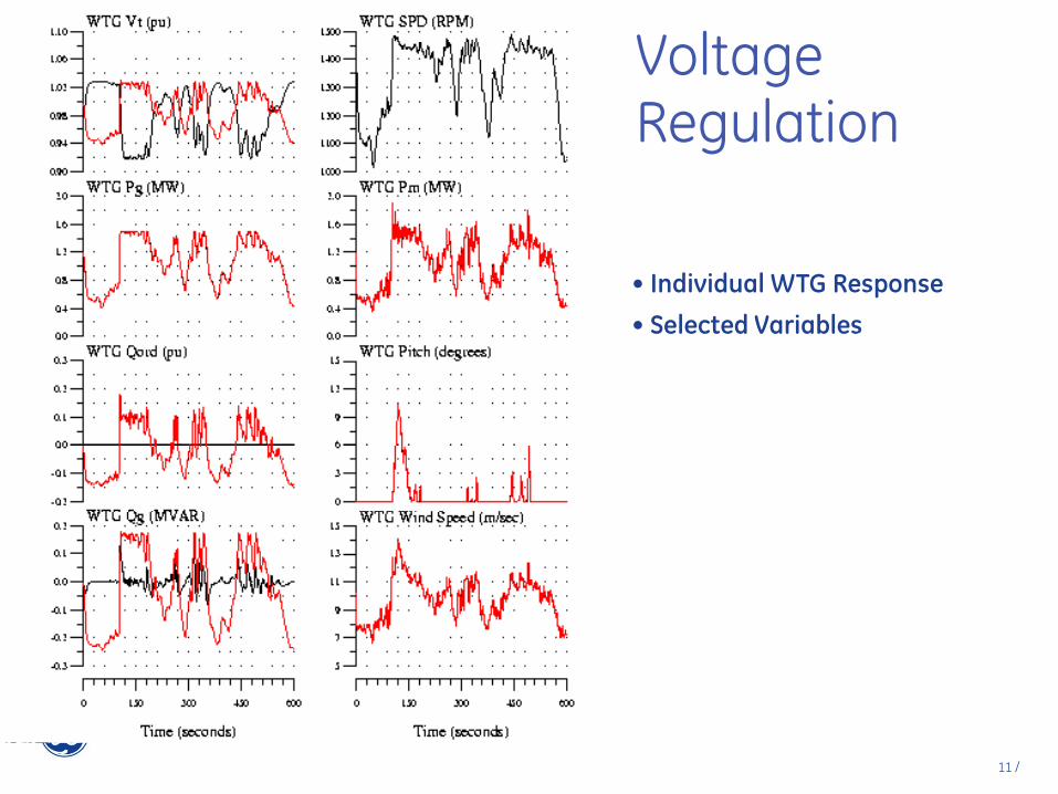
• Individual WTG Response
• Selected Variables
Voltage Regulation
Wind Turbine Fault Tolerance
13 /
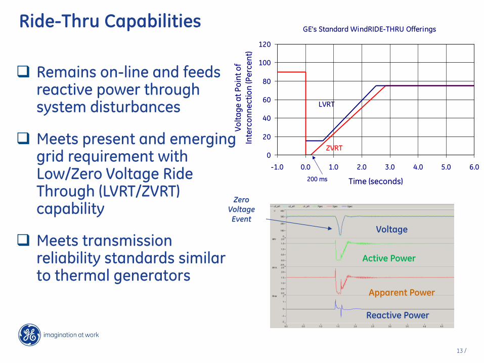
Ride-Thru Capabilities
Remains on-line and feeds reactive power through system disturbances
Meets present and emerging grid requirement with Low/Zero Voltage Ride Through (LVRT/ZVRT) capability
Meets transmission reliability standards similar to thermal generators
Active Power
Reactive Power
Voltage
Apparent Power
Zero Voltage Event
GE's Standard WindRIDE-THRU Offerings
0
20
40
60
80
100
120
-1.0 0.0 1.0 2.0 3.0 4.0 5.0 6.0
Time (seconds)
Vo
lta
ge
at
Po
int
of
Inte
rco
nn
ec
tio
n (P
erc
en
t)
200 ms
LVRT
ZVRT
14 /
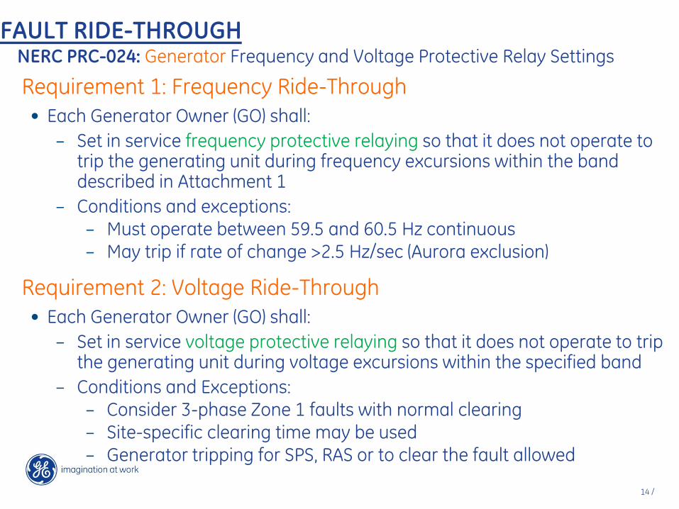
FAULT RIDE-THROUGH NERC PRC-024: Generator Frequency and Voltage Protective Relay Settings
Requirement 1: Frequency Ride-Through
• Each Generator Owner (GO) shall:
– Set in service frequency protective relaying so that it does not operate to trip the generating unit during frequency excursions within the band described in Attachment 1
– Conditions and exceptions: – Must operate between 59.5 and 60.5 Hz continuous – May trip if rate of change >2.5 Hz/sec (Aurora exclusion)
Requirement 2: Voltage Ride-Through
• Each Generator Owner (GO) shall:
– Set in service voltage protective relaying so that it does not operate to trip the generating unit during voltage excursions within the specified band
– Conditions and Exceptions: – Consider 3-phase Zone 1 faults with normal clearing – Site-specific clearing time may be used – Generator tripping for SPS, RAS or to clear the fault allowed

15 /
NERC PRC-024: Voltage Ride-Through
HVRT DURATION LVRT DURATION
Time (Sec) Voltage
(p.u.) Time (Sec)
Voltage
(p.u.)
Instantaneous 1.20 Instantaneous 0.00
0.20 1.175 0.15 0.45
0.5 1.15 0.30 0.65
1.0 1.10 2.0 0.75
3.0 0.9
Generators / Plant must not trip for credible faults inside the zone unless:
•SPS / RAS requires it
•Generator critical clearing time requires it (synchronous generators)

16 /
NERC PRC-024: Frequency Ride-Through QUEBEC
High Frequency Low Frequency
Time (Sec) Frequency (Hz) Time (Sec) Frequency (Hz)
0 - 5 66 0 – 0.35 55.5
5 -90 63 0.35 - 2 56.5
90 - 660 61.5 2 - 10 57
> 660 60.6 10 - 90 57.5
90 - 660 58.5
> 660 59.4
EASTERN INTERCONNECTION
High Frequency Low Frequency
Time (Sec) Freq. (Hz)
Time (Sec) Freq. (Hz)
0 – 10(90.935-1.45713*f) 61.8 0 – 10(1.7373*f-100.116) 57.8 10(90.935-1.45713*f)
- Continuous 60.5
10(1.7373*f-100.116) - Continuous
59.5
Continuous 60.5 Continuous 59.5
WECC
High Frequency Low Frequency
Time (Sec) Frequency (Hz) Time (Sec) Frequency (Hz)
0 – 30 61.7 0 – 0.75 57
30 – 180 61.6 7.5 - 30 57.3
>180 60.6 7.5 - 30 57.8
30 - 180 58.4
>180 59.4
ERCOT
High Frequency Low Frequency
Time (Sec) Frequency (Hz) Time (Sec) Frequency (Hz)
0 - 30 61.8 0 – 2 57.5
30 - 540 61.6 2 - 30 58
>540 60.6 30-540 58.4
>540 59.4
Transient Stability

18 /
Transient Stability
DFAG wind farms are more stable than conventional synchronous generators.

19 /
Transient Stability
In fact, wind farms will survive some disturbances that trip conventional synchronous generators.
Plant reactive coordination problems and solutions

21 /
WTG terminal Voltage with Uncoordinated PI regulators with PT error

22 /
WTG terminal Voltage with Uncoordinated PI regulators with PT error

23 /
Thermal
Plant
Thermal Plant Voltage Regulator
WF3
Grid
Several Miles
Several Miles
Connecting nodes
X1 X2 Wind Plant
Voltage Control
PT2
WF1 WF2
Wind Plant Voltage Control
Wind Plant Voltage Control
PT1
Multi-Plant Topology is Complex

24 /
Volt/Var Control (simplified block diagram)
Voltage Reference
Measured Voltage PI Control:
(Kpv, Kiv gains)
Voltage Error
Reactive Command to Wind Turbines
Droop: %, LPF
Reactive Power delivered from wind plant to grid
+ -
-

Study results demonstrating voltage droop

26 /
Where are we? Six Wind Plants in a region with relatively little load and a couple large thermal plants that normally anchor system voltage. Local penetration is high. Voltage management is significant challenge.
20% change in power from Wind causes ~4% dV at 230kV
27 /
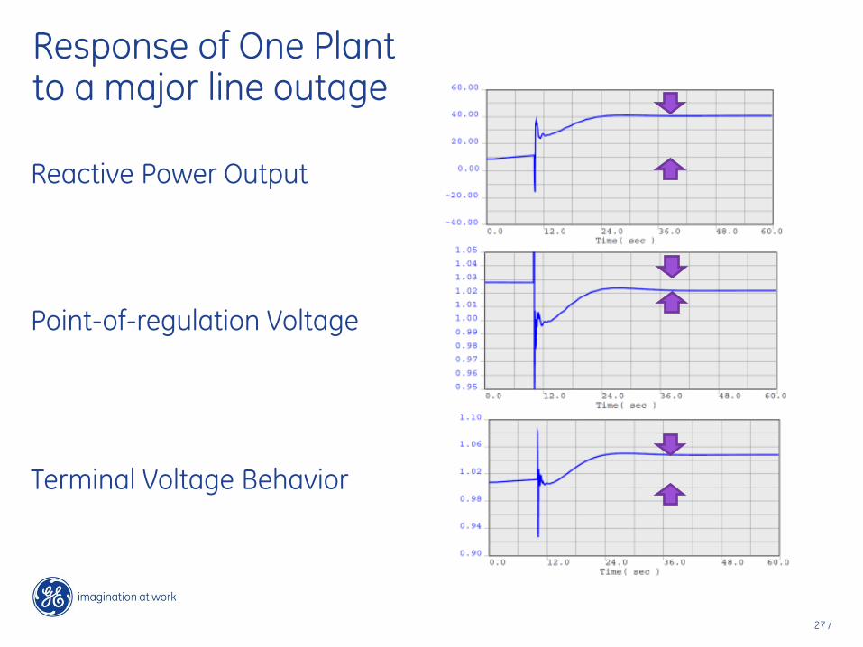
Response of One Plant to a major line outage
Reactive Power Output
Point-of-regulation Voltage
Terminal Voltage Behavior

28 /
Wind Plant Droops Field and Tuned Gains
Wind Plant Droop %
(on plant MVAr base)
Proportional
Gain
Integral Gain
Plant 1 5 6.0 1.5
Plants 2 1.3 1.5 0.5
Plants 3 1.3 3.5 0.83
Plant 4 2.0 0.18 0.09
Plant 5 1.3 1.5 0.5
Plant 6 1.5 0.4 0.2

Field test results
30 /
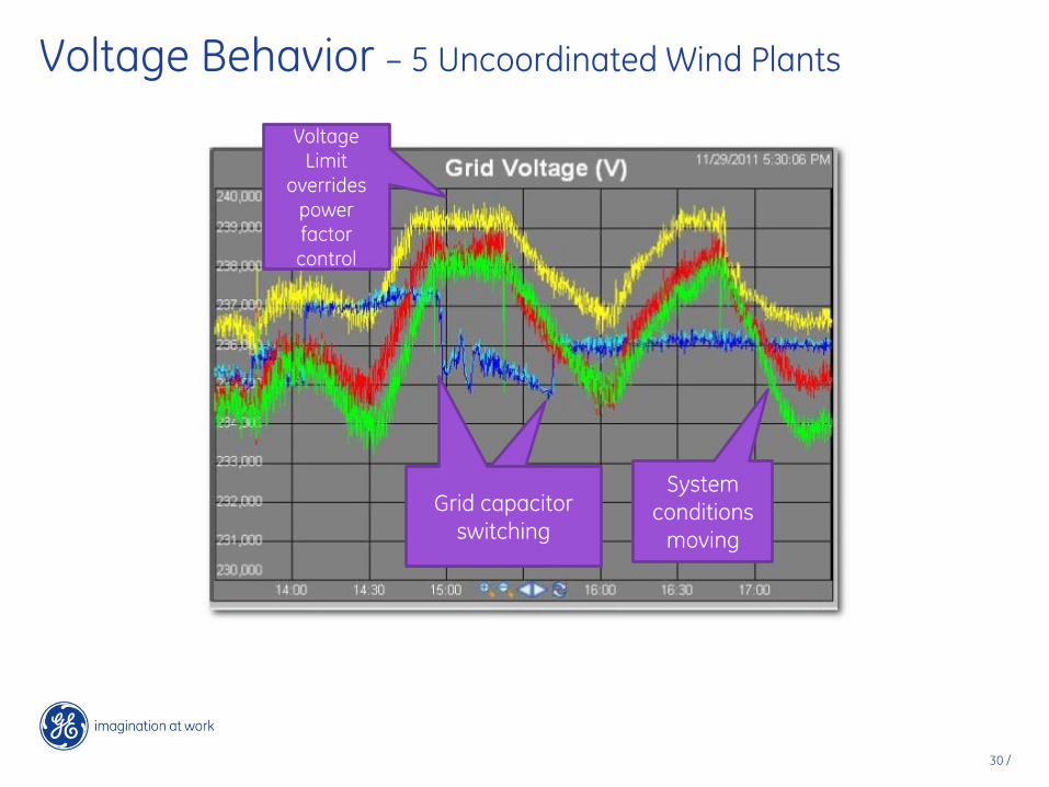
Voltage Behavior – 5 Uncoordinated Wind Plants
System
conditions
moving
System conditions
moving
Grid capacitor
switching
Voltage Limit
overrides power factor control

31 /
Voltage Behavior – 5 Coordinated Wind Plants
System conditions
moving
System
conditions
moving
Grid capacitor
switching
32 /
Thank You