cable management - diva-portal.se444434/fulltext01.pdf · the master thesis was preformed at...
TRANSCRIPT

Cable Management
System for Cabling in Different Radio Base Stations
ELIN MORBERG
Master of Science Thesis Stockholm, Sweden 2010


Cable Management System for Cabling in Different Radio Base Stations
Elin Morberg
Master of Science Thesis MMK 2010:99 IDE 056
KTH Industrial Engineering and Management
Machine Design
SE-100 44 STOCKHOLM


Master of Science Thesis MMK 2010:99 IDE 056
Cable Management
System for Cabling in Different Radio Base Stations
Elin Morberg
Approved
2010-11-
Examiner
Carl Michael Johannesson
Supervisor
Carl Michael Johannesson
Commissioner
Interconnect
Contact person
Peter Fagerlund
Abstract The Master Thesis was preformed at Ericsson in Kista at the division Interconnect
which designs the internal cabling for all Radio Base Stations (RBS). Due to the
complex usage of telecommunication today, many different RBS cabinets are developed
and they vary in capacity and design. The cabling is designed late in the development
process which results in unnecessary loss of usability. The goal is therefore to develop a
solution that can be applied in all the RBS cabinets so that the cabling becomes
consistent and more effective.
There are several smaller solutions at the market of cabling today but not an entire
system. The most common RBS cabinets are studied carefully and the knowledge of
these is essential to develop the most suitable system and to identify the necessary
requirements and functions. The strapping points in the RBS cabinets currently not
placed at the most suitable locations. Cable shelves and guides are placed everywhere
there are some extra space and a lot of these are never used. This contributes to that the
cabling has to be adapted to the strapping points and not the other way around.
To solve this, a concept is created to fulfill the requirements specification and then
developed into a cabling system. The system is based on two guides, one straight and
one curved, that are placed where the cables need extra support and guidance, such as
junctions and corners. Rails are running on the sides and with these the guides can be
attached together in different ways to fulfill the specific requirements of every possible
location. By combining the guides, the system also can separate different types of
cables, such as power and signal cables. In the same way, guides can be added to
enhance the cabling capacity to fit the number of cables.
The guides are manufactured in Polypropylene (PP) and with the manufacturing process
Injection Molding. The design is therefore adapted for the chosen process and material.
The two enclosing covers, which secure the cables inside the guides, are designed with a
so called ‘Living hinge’. It can therefore be made in one piece and with only one mold.
The cabling system requires a new way of thinking and a development process which
includes the cabling in an earlier stage. I believe that the system has a potential to create
a structured cabling and a generally accepted appearance inside every Radio Base
Station developed by Ericsson.


Examensarbete MMK 2010:99 IDE 056
Kabelhantering
Utveckling av Kableringssystem för Olika Radiobasstationer
Elin Morberg
Approved
2010-11-
Examinator
Carl Michael Johannesson
Handledare
Carl Michael Johannesson
Uppdragsgivare
Interconnect
Kontaktperson
Peter Fagerlund
Sammanfattning Examensarbetet utförs på uppdrag av Ericsson i Kista på sektionen Interconnect som
designar det interna kablaget i Radiobasstationer (RBS). På grund av den komplexa
användningen som används på telekommunikationsmarknaden idag så har olika RBS:er
utvecklats för kunna erbjuda varierande kapacitet och teknik. Det interna kablaget
utvecklas sent i produktutvecklingsprocessen vilken medför bristfällig
användarvänlighet. Målet är därför att utveckla ett system för hur kablarna skall kunna
dras på liknande sätt i olika typer av RBS:er.
Det finns redan enklare produkter som organiserar kablar på marknaden idag, men än så
länge inget heltäckande system. En studie av de vanligaste skåpen genomförs därför för
att underlätta utvecklingen av ett passande system och för att identifiera nödvändiga
funktioner och krav. En tydlig reflektion blir att placeringen av fästspunkter för kablaget
idag inte följer någon tydlig logik och många utvecklade placeringsmöjligheter förblir
outnyttjade. Detta medför att kablaget måste anpassas efter de befintliga
fästmöjligheterna och inte tvärt om som det är tänkt.
Utifrån förstudien tas sedan ett koncept fram och utvecklas därefter vidare till ett
kableringssystem. Två olika kabelguider, en rak och en böjd, placeras där extra stöd och
riktning behövs, t.ex. i kurvor. Med skenor på sidorna kan guiderna enkelt monteras
ihop på varierande sätt. Detta för att strukturera upp kablarna vid alla tänkbara
placeringar i skåpen. Genom att kombinera två guider av samma slag kan systemet även
skilja olika typer av kablar åt, såsom signal- och kraftkablar. På samma sätt kan
guiderna göra det möjligt att utöka kapaciteten om många kablar skulle samlas i ett och
samma utrymme.
Konstruktionen av kabelguider anpassas för att tillverkas i Polypropen (PP) och med
tillverkningsmetoden formsprutning. De två säkringssnäppen som säkerställer att
kablarna hålls på plats är konstruerade med ett gångjärn i plast. Detta gör det möjligt att
tillverka varje guide som en hel detalj och med endast ett verktyg.
Det utvecklade kableringssystemet kräver ett nytt sätt att tänka, vilket medför att
kablaget måste finnas med i processen vid ett tidigt skede. Därigenom för att det skall
vara applicerbart och kunna användas på bästa sätt. Jag tror att systemet har gett
möjligheten att förbättra och strukturera upp kableringen samt skapa ett accepterat
utseende för samtliga av Ericssons Radiobasstationer.


Foreword Between June and November 2010 I conducted my Master Thesis and with this report I present the final result.
My name is Elin Morberg and I am a student at the department of Machine design at KTH in Stockholm, Sweden. I began my education in the fall of the year 2006 at the Master of Science program Design and product development, the last one and a half year with a focus on Industrial design.
I would first like to thank my examiner and supervisor at KTH, Carl Michael Johannesson at the department of Machine design, for his positive response of my thesis.
Second, I would like to say thanks for all the help I got from Ericsson during the project. The employees and consultants at Interconnect have given me a great deal of support and without them I would not have come this far in the development of the cabling system. A special thanks to my supervisor and the Interconnect manager Peter Fagerlund and the Interconnect designer Marie Lemberg who always seemed to have some spare time for my questions.
I would also like to say thank you to the Industrial and Mechanical designers, for inspiring discussions about my progress, the result or any other topic that suited the moment.
Thanks to all of you!
November 2010, Stockholm Sweden
Elin Morberg
2

3
Table of Contents
1 Introduction...............................................................................................................................10
1.1 Goal.......................................................................................................................10
1.2 Method..................................................................................................................10
1.3 Criticism of the sources ........................................................................................11
2 Theoretical frame of reference.................................................................................................12
2.1 Cables and cabling................................................................................................12
2.1.1 Types of cables .....................................................................................13
2.1.2 Bend radius ...........................................................................................14
2.2 Cable management................................................................................................14
2.3 Design for manufacturing, Injection molding ......................................................15
3 Empirics .....................................................................................................................................18
3.1 Ericsson.................................................................................................................18
3.2 RBS 6000..............................................................................................................18
3.2.1 RBS 6102 – Large Out Door ”LOD” ...................................................18
3.2.2 RBS 6101 – Small Out Door ”SOD” ...................................................20
3.2.3 RBS 6201..............................................................................................21
3.3 Usability................................................................................................................22
3.3.1 Usability exercises................................................................................22
3.4 The Interconnect Design Process..........................................................................23
3.4.1 Prestudy ................................................................................................23
3.4.2 Feasibility and New Connector Development......................................24
3.4.3 Execution..............................................................................................24
3.4.4 Pre series and serial production............................................................24
3.5 The Design of the cabling.....................................................................................24
3.5.1 Strapping points....................................................................................25
3.5.2 Labels ...................................................................................................29
3.5.3 Tools used in the design process ..........................................................30
3.6 Interviews .............................................................................................................30
4

3.6.1 Interview Lars Tolkstam.......................................................................31
3.6.2 Interview Magnus Karlsson..................................................................31
3.6.3 Interview Ulf Williamsson ...................................................................31
4 Analysis ......................................................................................................................................32
4.1 Cable ties, guides, shelves and labels ...................................................................32
4.2 Function analysis ..................................................................................................32
4.3 Requirement specification ....................................................................................33
5 Result..........................................................................................................................................36
5.1 Material and manufacturing..................................................................................37
5.1.1 Design for manufacturing.....................................................................39
5.1.2 Service life............................................................................................39
5.2 The cabling system ...............................................................................................40
5.2.1 Guidelines for development..................................................................46
6 Discussion and Conclusion .......................................................................................................48
6.1 Further work .........................................................................................................48
7 References ..................................................................................................................................50
7.1 Literature...............................................................................................................50
7.2 Internet references ................................................................................................50
7.3 Interviews .............................................................................................................50
7.4 Visits .....................................................................................................................50
7.5 Personal contacts ..................................................................................................51
7.6 Pictures .................................................................................................................51
7.7 Computer programs ..............................................................................................51
5

Table of Figures
Figure 1. The process of development for the cabling system. ....................................... 11
Figure 2. A stranded conductor is made of a number of thinner wires. ......................... 12
Figure 3. The twisted conductor is a compact and stable construction (Moore 1982). . 13
Figure 4. The construction of a low-voltage cable. ........................................................ 13
Figure 5. A medium-voltage cable results in a complex construction with five or more
specific layers. ................................................................................................ 13
Figure 6. The construction of a Coaxial cable with two conductors............................. 14
Figure 7. The shape of these cable management details secures the cables, ................. 15
Figure 8. An additional action has to be performed for the detail to enclose the cables,
(Richco 2010). ................................................................................................ 15
Figure 9. The RBS 6102 is called “Large Out Door” (Ericsson 2010). ........................ 19
Figure 10. The LOD with a full configuration of GSM technology. ............................... 19
Figure 11. The RBS 6101 is called the “Small Out Door” (Ericsson 2010).................. 20
Figure 12. A full configured SOD with GSM technology. .............................................. 20
Figure 13. The RBS 6201 is for indoor usage and is called IND (Ericsson 2010)......... 21
Figure 14. RBS 6201 with full configuration of GSM technology. ................................. 22
Figure 15. The figure illustrates the design process used by Interconnect, (Ericsson
HWDP 2007). ................................................................................................. 23
Figure 16. The strapping points are often illustrated with a photo and drawn arrows,
(Lemberg 2010). ............................................................................................. 25
Figure 17. The cable holder is used for strapping the cables where there are no natural
attachments in the nearest surroundings........................................................ 26
Figure 18. The cable shelf is developed to match the position of the RU and DU units. 26
Figure 19. Every cable has an exit when the external cables come from the top in the
IND cabinet. ................................................................................................... 27
Figure 20. The cable beam is used in the LOD and in the SOD cabinets for strapping
the cabling. ..................................................................................................... 27
Figure 21. The cable guide is found in the LOD and the SOD cabinets. It is used for
guiding the cables out of the way of the other units. ...................................... 28
Figure 22. Several rows of cable hoops are mounted inside the cabinet at each side to
provide the cabinet with additional strapping opportunities. ........................ 28
6

Figure 23. The different strapping components and cable guides, illustrated with
different colors. From the left: LOD 6102, SOD 6101 and IND 6201........... 29
Figure 24. The label gives information about what type of cable is used. ..................... 29
Figure 25. A wrap around label is used on power cables. ............................................. 30
Figure 26. To the left is Concept 1 made out of a polymeric material and to the right
Concept 2 that will secure the cables in place with the shape ....................... 36
Figure 27. The molds parting line for the cable guides during the injection molding
process. ........................................................................................................... 39
Figure 28. Two guides are used to control the cabling, one straight and one curved. . 40
Figure 29. Snap buckles makes it easy to secure the guides inside the cabinet. ............ 41
Figure 30. Two or more curved guides can be combined to increase the capacity of the
system or to separate different types of cables. .............................................. 41
Figure 31. Just like the curved guides, two or more straight guides can be combined
depending on the specific need of different locations..................................... 42
Figure 32. The two different guides can be combined with each other to steer them in
different directions.......................................................................................... 42
Figure 33. The guides support the existence of abnormalities by adding more cabling
options. ........................................................................................................... 43
Figure 34. It is often necessary to gather the cables before guiding them between units.
........................................................................................................................ 44
Figure 35. The cables are kept in place with two security covers, fastened inside the
guide. It is released again with a push from the outside. ............................... 44
Figure 36. A RBS 6101 cabinet, SOD. The cabling is made with the applied cabling
system. Note that the SOD is not designed to include the newly developed
cabling system. ............................................................................................... 45
7

Dictionary 1056 1056 is the document type number used for Requirement specifications.
1074 1074 is the document type number used for Cable Mounting Drawings.
AC Alternating Current.
Adobe Illustrator Computer program used for creating sketches, pictures and drawings.
Adobe Photoshop A picture and photo editing program.
Architectural pictures Schematic pictures of the units inside the cabinet.
Brainstorming Brainstorming is a method used for generating ideas. No negative thoughts or opinions are allowed during a session and all ideas are documented to be evaluated at a later occasion.
Cabinet When speaking of a RBS cabinet, it is mostly about the entire RBS system even though it is the external casing that is mentioned.
Cable Mounting An instruction of cabling used in production and made by Drawing Interconnect designers.
Connector There is a connector in each end of a cable. Its purpose is to connect the cable with the unit to allow the electrical current or signal to pass through.
DC Direct Current.
Dummy A Dummy is used to fill empty slots not used by other units.
GSM GSM is a widely used standard radio technology.
IP Implementation Proposal (IP) is a document for estimating the time and finance necessary for a specific project.
IS Implementation Sketch is a document used to identify risks and develop preventative actions.
Interconnect Interconnect is a division within Ericsson, which develops and the internal cabling of all Radio Base Stations.
LTE LTE is the newest standard of radio technology.
Mock-up A Mock-up is an early made model made for evaluate the usability and the projects progress. It is not a working prototype.
PR PR is the short term for Product Revision.
RBS RBS is the short term for Radio Base Station and is the name of several product families developed by Ericsson.
8

Requirement A Requirements specification is a documentation of specification requirements that are imposed on a product or project. Within Interconnect, this document also is called 1056.
RRA The Reliability Risk Assessment is a document for identifying the possible risks that could occur for the product.
Time Schedule A Time Schedule is the time-estimation and distribution of a project and all its stages.
Usability Usability is how the design and technology affects the user in a positive or negative way.
W-CDMA W-CDMA is a standard radio technology found in 3G telecommunications network.
9
1 Introduction Ericsson is a Swedish company with approximately 87 000 employees around the world. The company focuses on the development of telecommunications equipment and related services to mobile and fixed network operators globally.
In 2008, Ericsson released a new series of Radio Base Stations (RBS) to the market, RBS 6000. The new RBS 6000 product family can use all of the standard radio technologies in the same cabinet, all at once or one at a time depending on the requirements of the customer. The many configuration options now available have resulted in a more difficult assembling process which has made the cabling of the cabinets a second priority.
Due to the different RBS cabinets, which vary in size and capacity, it is usually different designers that make the cabling in each separate project. Because of a tough time schedule the result differs in both function and appearance. Lack of usability has also become a common issue when the design is being made as the very last step in the development process.
1.1 Goal Although all RBS cabinets are developed by Ericsson, it is clear that the design of the cabling is different depending on who has made it and when. The solutions are almost as many as the number of different RBS configurations. A cabling system would therefore reduce the variety of cables, which in turn would cut the costs per cable, and result in a unified appearance for the cabling.
The goal of the assignment can be summarized:
Develop a RBS cabling solution based on the requirement specification and with an Industrial design perspective. The system shall be applicable on different RBS systems.
Study the synergy between different RBS systems and identify common elements and structures of the industrial design. With this in mind, minimize the variation of cables.
Create an Ericsson look which concerns the cabling. The new look shall be accepted by the intern interfaces (Product management, System, Bugs, Site etc).
Besides improving the appearance and usability, the system is to make the design of the internal cabling more controlled in the future, with guidelines to work with. The cabling system will therefore be applied in one of the RBS 6000 products to enhance the understanding of the developed guidelines.
The development of the assignment could result in a far too large project which concerns many of the units and cabinets. Because of the time limitation the development are focused on a system replacing the cable ties, the holders and guides and if possible also minimize the tags on the cables.
1.2 Method The development of a cabling system begins with a theoretical research about cabling in general. When the basic information is gathered, it continues with an empiric study of the RBS cabinets and its cabling. This empiric study is to be used to analyze the RBS
10

cabling and shall result in a requirement specification and function analysis. These are in turn used as tools for the continued development and as foundation for the future concept. An illustration of the method can be seen in Figure 1 where two connected circles describe the development process.
Figure 1. The process of development for the cabling system. When the background is defined, the development begins with several brainstorming sessions that eventually will form the different ideas. These are taken further with detailed sketches and designed in CAD (Computer Aided Design) to create concepts that can be compared and evaluated. One concept is chosen for the cabling system and is sent to a model workshop for prototype production. The prototype is tested, evaluated and if the results are not satisfactory, new CAD models are designed and finally also new prototypes. This step is to be repeated until the design meets all the requirements.
1.3 Criticism of the sources It has been important to use a variety of sources when searching for information on a specific topic. Literature and interviews has been the major information source and the number of internet references has been kept to a minimum. When using internet, the listed sources has been studied and if possible, these references are used instead to reduce the possible information losses that for example translation of information could result in.
Interviews have been an important information source and the different expertise’s resulted in a wide range of opinions and preferences. These opinions had to be translated into useful facts and compared with each other.
11

2 Theoretical frame of reference
To gain the basic knowledge about cabling and its limitations a theoretical research is made. It will form a foundation from where the empiric study of the problem can be made and later on, also the development of a cabling solution.
2.1 Cables and cabling An electrical product includes and depends on cables and the transition of power and signals. The definition of an electrical cable is that it has a conductor as core which is isolated with an insulation to keep the electrical currents separated (Moore 1982). A conductor is made out of a low resistant metal, for example copper, and leads an alternating (AC) or direct current (DC) through the cable. The single-core cable is the most common and simplest electrical cable but as the voltage increases the design becomes more complex and the number of conductors rise. Depending on the purpose of the cable, other components may include such as armoring for mechanical protection or corrosion protection.
It is usual today to use stranded conductors. A stranded conductor is made of several thinner wires that together form the conductor of the cable, see Figure 2. The stranding results in new mechanical properties which are desirable in various cases, for example in moving applications. The thinner wires are more flexible and as they together form a single core, it will also become easier to handle.
Figure 2. A stranded conductor is made of a number of thinner wires. The electrical properties can also vary because of the stranding and the resistance in the conductors can be reduced. If the resistance is increasing it is because of an electrical phenomenon called the skin effect. The skin effect occurs when the concentration of alternating electrical current (AC) is greater at the surface of the conductor than in the core (Rozenblit 1999). The increased resistance is higher for cables with larger diameter and at higher frequencies, often used in radio transmission. The usage of stranded cables almost eliminates the negative effect because of the higher number of thinner wires that together creates a conductor without one single core.
To reduce the size of the cable, it is common to use shaping rolls to achieve a compact solution (Moore 1982). The rolls used for shaping the cable results in a twisted lay which have several benefits, see Figure 3. When multiple cores are laid, there is no need to twist the cores as a preparation of the manufacturing and the construction becomes more stable which reduces the possibility of damage the isolation.
12

Figure 3. The twisted conductor is a compact and stable construction (Moore 1982).
The cabling is often organized with cable ties and bundled together or fastened. The purpose is to clear the view from other units included in the product and make it easier to locate and repair malfunctioning components.
2.1.1 Types of cables
The construction of the cable depends on the usage, the application and the surroundings. A short description of the general cable design and their uses are described in this chapter and because the numerous of existing cable types, only the most common are presented.
Cables for low-voltage, less than 2 000 Volts, have one center conductor which is surrounded by isolation, see Figure 4. An alternative jacket may cover the isolation and though it may have some insulating properties the actual isolation still depends on the specific insulation layer (Cadick 1999).
Figure 4. The construction of a low-voltage cable.
As the electrical stress increases, so does the complexity of the design of the cables. A medium-voltage cable has a capacity up to 35 000 Volts and is composed of five or more different layers were every layer has a specific purpose. Counted from the center and out, the most commonly used layers are: Conductor, Semiconductor, Insulation, Semiconductor, Metallic Shield and Jacket, see Figure 5. The purpose of the metallic shield is to contain and equalize the electric field inside the cable and without it, the field would be unevenly distributed. As mentioned before, the jacket is the protection from the surrounding environment.
Figure 5. A medium-voltage cable results in a complex construction with five or more specific layers.
13

A communication cable called Coaxial cable is used to transmit radio frequency signals and is constructed with two conductors. The first is in the center of the cable and the other is formed like a tube and separated from the first conductor with a thick isolation, see Figure 6.
Figure 6. The construction of a Coaxial cable with two conductors. The tube-like conductor is called shield and the main purpose is to contain the created electromagnetic field inside the center conductor. The conducted current is AC and the flow change direction many times per second. Without the shield the cable would therefore work as an antenna, causing power losses.
2.1.2 Bend radius
When a cable is used there is a desire of flexibility to make the cabling easier to control. Methods of manufacturing and cable design have been developed to create cables that have the possibility to meet these requirements (Cadick 1999). It is known that stranded cables are more flexible because of the smaller wires that combined forms the center conductor. More wires within a specific diameter results in more controllable cable, but the more complex design affects the manufacturing process and therefore increases the costs. It is important to determine how much a softer cable is allowed to cost and to have a continued discussion with the manufacturer to develop a requirement specification for every cable.
The manufacturers and cable suppliers defines the minimum bend radius according to the customers requirements and as long as the cabling meets their demands, they guarantee the cables service life.
2.2 Cable management There are many solutions of how to control cables but the basic principle is to gather and secure the cables in chosen positions. Richco is a company that specialized on fasteners, wire routing products, cable ties, fiber optics and telecommunication accessories among other. When examining their selection of cable management products, it becomes clear that they usually are attached with a screw or snap attachment. Two types of cable management products were identified out of the Richco catalogue. The first type encloses the cables with the shape of the design, see Figure 7, and the other type is in need of an additional physical action. Closing the detail is an example of a possible additional action and can be seen in Figure 8.
14

Figure 7. The shape of these cable management details secures the cables, (Richco 2010).
Figure 8. An additional action has to be performed for the detail to enclose the cables, (Richco 2010).
Cable management is a known problem area and the existing cable management products seems to be almost infinite, but no entire solution is yet developed. The nearest you get to a system is the white cable guides that can be found in most homes, attached to the lower walls and hides the cables behind a cover.
2.3 Design for manufacturing, Injection molding Depending on the manufacturing process and the material choice, the design of a product some times has to be modified for an optimal production (Sweeney 1987). A common manufacturing process for polymers is Injection molding. The production method has the capability to produce detailed products without any after processing and the cost depends on the complexity and volume of the product.
An Injection molding process uses an injection unit, a clamp unit and a mould with the cavity of the product which usually are divided into two parts. If the product is complicated, the mould can be divided into more than two parts, though it will add to the manufacturing costs (Roy and Chanda 1987). The injection unit can be described as a plastic extruder that adds melted polymer into the cavity with a rotation screw within a barrel. The clamp unit is a press that holds and fixes the mould. With a force greater than the pressure contributed by the flow into the cavity, it makes sure that the different mould parts are not being separated during the injection process. Because of the force
15

depending on the size and volume of the product produced, a larger product will need a greater force from the clamp unit.
When designing a product in a polymer material it is important to know how the manufacturing process affects the final result (Morton-Jones 1986). It is therefore necessary to follow some rules and guidelines to avoid changes of the design later in the design process. Mainly it is about adapting the design to the manufacturing process.
The design should let the material flow through the cavity without turbulence or disturbances and the speed of the flow is to be decided by the injection unit, not the design. Thick sections in the design results in a slower material flow and could result in turbulences which are not recommended. According to Morton-Jones (1986) the main design shall therefore have an even thickness of the material. Another design detail that contributes in a smoother material flow is fillets and corners with a radius. For optimal flow it is recommended to have the radius set on at least 0.125 inches (about 3 mm). The radius also makes the demolding of the part easier when the process is finished.
A complex design results in more costs and more complicated moulds but the number of parts needed could be reduced by designing the product for demolding. Straight corners and angles make it more difficult to separate the mould after the injection and the risk of damage the part increase. Narrow walls and sections shall therefore be designed with a draft angle of minimum 1.5 degreese (Morton-Jones 1986).
Depending on the number of parts which are to be produced, costs can be reduced by minimizing the material needed for one part. In a larger scale it could make a huge difference. More material results in a stiffer product but this stiffness can be achieved by other means. Recognized methods are adding lips and ribs but also a change in the design could be enough. This could be flanges, one or more, or curved, stepped and angled walls. To realize that it is not the amount of material that contributes to a stiffer design, is a vital step to create a cost and material efficient design.
16

17

3 Empirics
The following chapter describes the process used by the Interconnect designers and the Radio Base Stations that they develop. It is important to interview a wide range of persons to determine how the theoretical process differs from the actual working process. These differences are identified and the cabling design status is documented and analyzed.
3.1 Ericsson The Swedish telecommunication company Ericsson was founded in 1876 as a telegraph repair shop (Klemens 2010). In the early years the main activity was producing telephone equipment but only twenty-five years later LM Ericsson was known as a leading international telephone company with over 500 employees.
Today’s development is mainly of radio technologies and communication systems (Alla Bolag 2010) and the well known product called Radio Bas Station (RBS) has been recognized as a known term. Since the year of 2001 Ericsson owns the mobile phone company Sony Ericsson together with the technology company Sony.
3.2 RBS 6000 A research is made to gather knowledge about the new RBS 6000 units and the technologies involved. Three RBS cabinets are studied more thorough and full configurations are illustrated in Adobe Illustrator to visualize the projects working area.
RBS 6000 is Ericsson’s new series of base stations and it includes a number of different RBS cabinets of varying purposes and possibilities. The size and capacity depends on the costumer demands and in which climate it is operational (Ericsson 2010). The standard radio technologies used are GSM, LTE and W-CDMA and the RBS 6000 has the possibility to contain several technologies in the same cabinet. A multi standard technology is also developed to handle all the standards at the same time. For a more detailed list of included units inside the RBS cabinet and their purpose, see Appendix A) – Description of the units in a RBS.
3.2.1 RBS 6102 – Large Out Door ”LOD”
The RBS 6102 is the largest member of the RBS 6000 family. It is called ”Large Out Door” and therefore it is generally named LOD. The name indicates that the RBS is developed for outside usage (Ericsson 2010) which has resulted in a more generous cabinet size, see Figure 9.
18

Figure 9. The RBS 6102 is called “Large Out Door” (Ericsson 2010).
Inside the cabinet there is space between units and sub racks, a full GSM configured LOD with batteries can be seen in Figure 10. This configuration has been identified as one of the most disorganized by Interconnect designers. In general, the LOD cabinet is assembled as follow: In the top of the cabinet are one standard and one optional climate system. Below these are the Radio (RU) and Digital Units (DU) divided at either side of the centered sub rack, the number of units depends on the need of the customer. Batteries are located in the in the rack with the lowest position because of their weight. Centered in the LOD cabinet are the control and power supply units which has to be reachable from the entire cabinet.
Figure 10. The LOD with a full configuration of GSM technology.
19

3.2.2 RBS 6101 – Small Out Door ”SOD”
The RBS 6101 is smaller and more compact than the LOD. The cabinet is named ”Small Out Door” and it is designed for outdoor usage as well. An assembled SOD cabinet, though without the cables, can be seen in Figure 11.
Figure 11. The RBS 6101 is called the “Small Out Door” (Ericsson 2010).
In contrary to its larger family member, the SOD cabinet does not have much extra space and the design is made without any room for error. Due to the smaller cabinet size, the maximum capacity isn’t as high as for the larger cabinet. The wiring is, however, similar to the one described earlier. A full configured SOD with GSM technology can be seen Figure 12.
Figure 12. A full configured SOD with GSM technology.
20

3.2.3 RBS 6201
RBS 6201 is a base station for indoor usage and is therefore called IND. The incoming power cables can either come from the bottom or the top via cable ladders, see Figure 13.
Figure 13. The RBS 6201 is for indoor usage and is called IND (Ericsson 2010).
The cabinet is about the size of the SOD but the requirements are less demanding for cabinets that are constructed for indoor usage. Therefore the design of the IND differs from the outdoor cabinets in both function and appearance. The fact that the IND has been developed by an entirely different division at Ericsson, independent from the outdoor RBS development, has also contributed to the differences in design.
Because of the indoor location, the usage of an external climate system is not necessary and the internal fans are located at the top of the cabinet, behind the control and power supply units. Unlike the outdoor cabinets, the usability and design of the IND has been reviewed and improved recently. The obvious difference in the appearance is a resulted effect but as modular design gets more influence within Ericsson these differences most likely will be reduced in time. A full configured IND can be seen in Figure 14 with GSM technology.
21

Figure 14. RBS 6201 with full configuration of GSM technology.
3.3 Usability Often during a development process, the term ‘Usability’ is used to describe the stage when the product is evaluated from the user’s perspective. Usability is about the interaction between, for example, the assembler or manufacturer and the RBS. Some common questioning are:
How should the RBS cabinet be assembled?
Can the units be replaced without any interference or disturbance?
How is the cabinet transported and carried to the site?
The purpose of the usage of usability during the development process is to locate problem areas so that it can be solved before the product reaches the market (Siverbäck 2010). You could say that usability is a preventative stage in the development process. It results in less time needed for manufacturing, installation and maintenance.
3.3.1 Usability exercises
It is important to make all the necessary preparations before a usability exercise is performed (Siverbäck 2010). The most common preparations are:
22

Determine which participants are needed. Different departments should be represented. Assign persons to take notes and be responsible for the documentation. Photos and videos are a useful tools for evaluating the exercise at a later occasion.
Decide how the RBS cabinet should be equipped before the usability exercise.
Decide what hardware is needed for the test and make a list of the necessary equipment.
Define the purpose of the exercise, what are to be evaluated?
Create an agenda with a concrete time schedule for each task to be performed.
Send invitations and book a conference room suitable for the exercise.
When the preparations are made, the usability exercise is held. This should occur at several occasions during the development process of a RBS for best results. Common tasks performed during these occasions could be to install and replace units or cables. If there are any difficulties for a certain task, the situation is discussed and the problem documented. The documentation of the usability exercise serves as an input to the ongoing design process and identified problems must be solved.
3.4 The Interconnect Design Process The Interconnect designers have their own design process (Ericsson HWDP 2007). It serves as a tool when making all the necessary preparations and creating the design of the cabling and forms the foundation for the manufacturing and assembly, see Figure 15. According to the Interconnect designer Marie Lemberg (2010), a project usually lasts about one or two years. The development process is therefore important to prevent missing a significant step that could result in difficulties later on.
Figure 15. The figure illustrates the design process used by Interconnect, (Ericsson HWDP 2007).
3.4.1 Prestudy
A project begins with a prestudy which is a method of distributing the time available and prepare for eventualities and risks. Interconnect primarily participate in the discussion concerning the overall cabling and connections between different units.
23
Meetings are held between the involved departments to discuss the included components and units, rate the identified risks and work together to develop the documents and gather information necessary for the continuing project. Document created are the Time schedule, the Implementation Sketch (IS) and a document with general information on risks and preventative actions, the RRA Report. The RRA discusses risks concerning the actual product and is made to secure the quality and capacity. The necessity of Interconnect participating in writing these reports depends on the project and the time available.
3.4.2 Feasibility and New Connector Development
The project proceeds with an evaluation of the information gathered in the IS. Interconnect participate in working with the development of the Implementation Proposal (IP), which include estimating time and finance necessary. All cables have to be specified and this is done by translate and interpreted architectural pictures and 2D or 3D models of the cabinet and units, made earlier in the project by other departments. These pictures and models are studied to determine how to connect the cables between the different units. Mock-ups are made to help this process of preparing the cable mounting drawings and the continuing to the execution step.
3.4.3 Execution
The design is developed from the study of the architectural pictures, but before cabling is possible, a Requirement Specification (called 1056) is made with vital demands and requirements for the designer. The development continues with the work of a Cable Mounting Drawing (called 1074) and a Manufacturing Specification. The 1074 is useful for many different departments, but as main purpose it is created as an instruction for mounting the cables in the RBS for different configurations.
The result from the execution phase is documents and materials that make the RBS ready for pre series production. Participation in meetings regarding the pre series preparation and the assembly is important to be able to identify possible problems or design flaws. Usability exercises are common in this stage of the process and an important tool in the development of a RBS. It is also important to update the contact with the possible suppliers and continue the ongoing dialogue with the production unit.
3.4.4 Pre series and serial production
At this stage in the project it is time for the design to be tested and evaluated in order to determinate if the product meets all of the requirements. Documents from the suppliers are gathered and reviewed. Then it is time to decide if the product is ready for pre serial production or if further development is needed. It is ready when the suppliers ensure the design and quality necessary for all the individual units and components.
When the pre serial production is done, the next step is to verify, evaluate and analyze the results and the concerned documents from the suppliers. It is also important to participate in briefings about public relations. If the requirements are fulfilled and the pre serial product is satisfying, it is time to begin with the serial production.
3.5 The Design of the cabling Because of variation in size and configuration depending on the requirements of the customer, the cabling of RBS cabinets is complex and differs between products. The smaller unit, SOD has a cabinet with no room for error or extra space, unlike the larger
24

LOD which has a cabinet with longer distances between the different components. During the design of the cabling, each RBS have encountered various problems and this chapter summarizes the current situation as well as the Interconnect view.
There are several requirements about the cabling concerning the capacity and preventing units interfering with each other. All has to be taken under consideration during the design process, but not at the expense of the usability.
3.5.1 Strapping points
To organize the cables inside the RBS, strapping points are used, and the cables are bundled together with straps at the sides or at locations made for that specific purpose of attachment. For strapping cables, standard cable ties are used in the RBS cabinets. The strapping attachments could be extra beams, holes or rails which are placed between sub racks and at the sides of the cabinet, out of the way of the other units in the RBS. Every type of RBS has specific strapping points and they are presented in the belonging 1074 (Lemberg 2010). The illustration is often a photo or sketch of an available configuration and arrows is drawn to show possible strapping points, see Figure 16. If some units have to be replaced, for example because of units malfunctioning, the access of the concerned units has to be easy and cables out of the way. Therefore it is important when placing strapping points to note the possibility of repairing or upgrading the RBS in the future.
Figure 16. The strapping points are often illustrated with a photo and drawn arrows,
(Lemberg 2010).
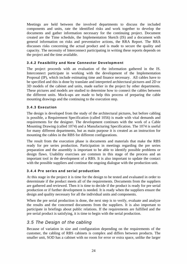
The IND, RBS 6201, has special developed cable holders, three at each side in the cabinet, see Figure 17. These are for strapping the cables out of the way from the units and to improve the usability.
25
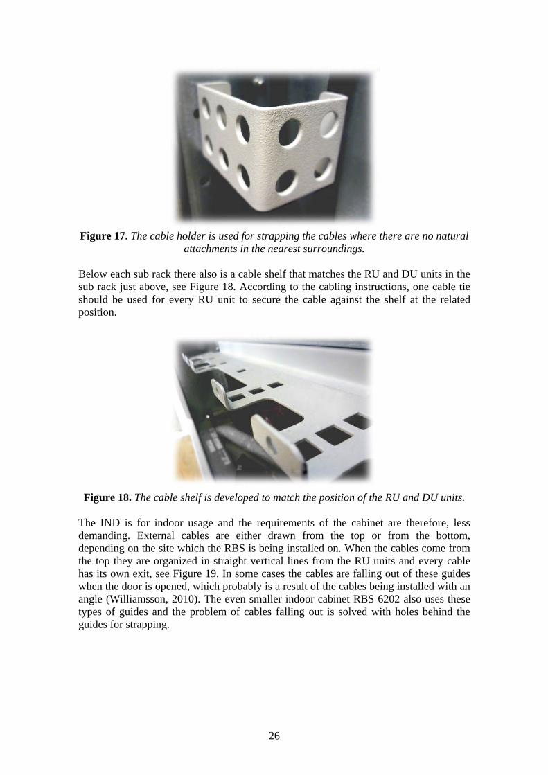
Figure 17. The cable holder is used for strapping the cables where there are no natural
attachments in the nearest surroundings. Below each sub rack there also is a cable shelf that matches the RU and DU units in the sub rack just above, see Figure 18. According to the cabling instructions, one cable tie should be used for every RU unit to secure the cable against the shelf at the related position.
Figure 18. The cable shelf is developed to match the position of the RU and DU units. The IND is for indoor usage and the requirements of the cabinet are therefore, less demanding. External cables are either drawn from the top or from the bottom, depending on the site which the RBS is being installed on. When the cables come from the top they are organized in straight vertical lines from the RU units and every cable has its own exit, see Figure 19. In some cases the cables are falling out of these guides when the door is opened, which probably is a result of the cables being installed with an angle (Williamsson, 2010). The even smaller indoor cabinet RBS 6202 also uses these types of guides and the problem of cables falling out is solved with holes behind the guides for strapping.
26

Figure 19. Every cable has an exit when the external cables come from the top in the
IND cabinet.
Neither one of the cable holders or shelves that are found in the indoor cabinet is in use in the outdoor cabinets, LOD or SOD. Variations in the cabling design are more obvious between different cabinets and configurations due to the less developed strapping point. In both of the outdoor cabinets there is at least one cable beam which makes the strapping possible, see Figure 20. For the LOD there are two cable beams, one at each side of the central rack and the SOD has one beam which is mounted to the left of the sub racks.
Figure 20. The cable beam is used in the LOD and in the SOD cabinets for strapping the cabling.
In the LOD and SOD there are cable guides above the sub rack and power units. They are used for guiding the cables without cable ties, see Figure 21. The order in which the cables are mounted in the cable guide depends on the order they are assembled. The LOD has two cable guides, one above each sub rack, and the SOD has one.
27

Figure 21. The cable guide is found in the LOD and the SOD cabinets. It is used for guiding the cables out of the way of the other units.
As a precaution, extra cable attachment possibilities are placed at the sides inside the cabinet and above the climate system located at the top of every outdoor RBS cabinet. Many attachment options are needed when the cabling routes are not determined before the design of the cabinet is set. Extra hoops give some extra security, see Figure 22, but only a small number of them are used at all.
Figure 22. Several rows of cable hoops are mounted inside the cabinet at each side to
provide the cabinet with additional strapping opportunities. The three RBS units are compared with each other and in Figure 23, the different options when cabling are illustrated. The similarity of the location of guides and strapping components between the LOD and SOD cabinets are obvious and the IND unit has new strapping components and a different layout. The development of a system for cabling must therefore be adaptable and applicable in different structures and a wide range of configurations.
28

Figure 23. The different strapping components and cable guides, illustrated with
different colors. From the left: LOD 6102, SOD 6101 and IND 6201.
3.5.2 Labels
In the RBS units there are several different cables, signal and power cables. These are labeled with one or two white plastic tags. Every cable has a tag which gives information about length and what type of cable is in use, see Figure 24.
Figure 24. The label gives information about what type of cable is used.
All power cables are also labeled with an additional wrap around label with the information 20 A, see Figure 25. Because of the lack of space on the units where the connectors are attached, this information was moved from the units to the cables some time ago. The label is stiff and because of its location, close to the connectors, the cable becomes difficult to handle for short lengths (Lemberg 2010). In some cases the label is removed completely despite the requirement of their existence.
29

Figure 25. A wrap around label is used on power cables.
3.5.3 Tools used in the design process
There are a couple of computer programs used by Interconnect during the design process. A program called PIwin is used to store documents concerning every product and unit, parts or assemblies. When creating drawings and pictures in the common document 1074, Interconnect uses Microsoft Office Visio 2003, which is capable of creating illustrations of the cabling design. The outcome depends on the Interconnect designer and the result can vary between the different 1074 and RBS cabinets.
3.6 Interviews A handful of interviews are made to gather different opinions and visions from employees and other experiences. In this case, the designer is the one who directly is concerned by the result, but a solution will in one way or the other also affect the production, the assemblers, the installers and the suppliers. A wide perspective is therefore important and the questions used during the interviews can be found in Appendix B) – Interview questions. The summarized result of the interviews are described and analyzed in this chapter.
A common opinion gathered from the interviews is that the new RBS 6000 family looks better and more structured than its predecessor, the RBS 2000 and 3000 families. The number of cable variations has been reduced and the strapping points more developed with the focus on usability.
Because of reduced costs of the cabling, the cables are being stiffer than before and the handling is therefore demanding, as a result of the cheaper alternatives. To ease the assembling process and reduce the stress developed in the cables, a wish is to have more flexible cables to decrease the cable bend radius. This would not only make the assembling and the installation of the RBS cabinets easier, it would also reduce the possibility of a system malfunctioning because of the bending radius is being ignored.
It has become clear that the cable assembling process, made by Interconnect not always is followed. If it is because of the complexity or the numbers of strapping points was not clear. The instructions used are made from the 1074 document created by Interconnect but with the wide range of strapping possibilities, the assembler is the one to make the final decision. It should not be possible to do the cabling in another way and a well prepared cabling solution would eliminate the individual influence of the cabling route.
30

3.6.1 Interview Lars Tolkstam
Lars Tolkstam is working in Kumla as a Quality Engineer. As a Quality Engineer, he works as a connection between the designers and the suppliers. He also ensures the quality of the product and the production process. The work mostly concerns the new 6000 series and products developed by Interconnect.
The work begins when the design of the product is decided and a supplier is chosen. This late involvement results in a slim possibility to modify the product and if the supplier should suggest a technical change to the design or production, it takes more time and effort to carry it out. Therefore the focus is set on developing the production and the quality requirements, ensuring the production quantity and creating a risk analysis for the chosen supplier (and sub supplier).
When asked about the usability in the RBS cabinets today, Tolkstam mentions the importance of a design which simplifies the production for the supplier and sub supplier. The involvement of the production earlier in the project would result in fewer misunderstandings.
3.6.2 Interview Magnus Karlsson
Magnus Karlsson is a Production Engineer in Gävle. He mainly works with the SOD cabinet (RBS 6101) but also with other older cabinets. In an early stage of the development process he seeks to contribute with a production point of view, with focus on the productivity and manufacturing process. Karlsson also creates the assembling instructions out of the 1074 made by Interconnect and is therefore involved in the development and the review of these documents.
For Karlsson the word usability is about the working process, when manufacturing a product. All parts, components and units must be easy to produce, transport and assemble. No special developed tools are to be used and standards are therefore important. If possible, the development of snap buckles is done and the usage of any tools is reduced to a minimum. The flow through the factory shall be even, flexible and efficient. His experience with the work of usability and usability exercises are many but often it is performed with a simple test, or no tests at all, just for the single possibility to check off another step of the process. This could result in poorly executed usability exercises, although it is a priority.
3.6.3 Interview Ulf Williamsson
Ulf Williamsson is working with the installation of RBS cabinets on site. As a project proceeds, he participates in the product development to speak for the final installer and to study the assembling possibilities. The connection and cooperation with the designers and technical designers is constantly improving to reduce the risk of late design changes or problem surfacing when installing on site.
Williamsson is involved in an early stage in the development process when often only an idea is formed. Early product descriptions are important to form an opinion about the final result and possible limitations when assembling and during installation.
Usability exercises are good for ensuring the assembling possibilities and installation process from the customer’s point of view. It is also important to study the case of future maintenance and services of the RBS cabinet and all of the units must be replaceable without having effects on other units or the cabling.
31

4 Analysis
The empiric study helps to identify the flaws of the existing cabling and it is now easier to find the areas needing further development. This is done by analyzing the result of the empiric study and in the end of the chapter forms a more detailed and narrow scope of work.
4.1 Cable ties, guides, shelves and labels In the RBS units today the cable guides are located at the sides and between racks and units, not in corners or junctions. Therefore the control of the cables direction is not optimal. An additional component, cable ties, is needed to make sure the cables are fastened properly. The cable ties are extra, loose parts and if a unit in the RBS has to be upgraded and the cables removed, the ties has to be cut open and replaced by new ones which not always are available.
By integrating more of the required functions in fewer parts, it is possible to reduce costs and the numbers of possible problems in the manufacturing process. Though the system in development is supposed to operate for every customer requirement, the most common ordered base station is not delivered with a full configuration. The large number of strapping opportunities is therefore in most cases unnecessary but because of the shelves and guides not being optional, a lot of material and strapping points are without a purpose. If a replacement for the existing shelves and guides are created, it should be adaptable depending on the configuration, but with the possibility to enhance the cabling capacity if the RBS is upgraded in the future. The system should also be easy to use and understand, to avoid misunderstandings.
4.2 Function analysis A system of cabling must consider numerous of different aspects. A function analysis has therefore been made to identify the more important areas of development, see Table 1. The Functions are classified in the categories Main Function (MF), Necessary (N) and Desires (D) and they are color coded depending on their importance. Red indicates that the function is a must for the cabling system and it is therefore not optional. Green in other hand is a function that would enhance the product but the system could be operational without it.
Table 1. Function analysis for the cabling system.
Function Class Function interface
Allow Support MF Cables/Cable guides and shelves
Control Direction MF Cables/Guides
Allow Direction N Cables/Cable guides and shelves
Allow Adjustment N Guides and shelves
Provide Placement D Cables/Guides
Offer Guidance D Cables/Guides
Own Flexibility D Guides and shelves
Have Adjustability D Guides and shelves
Radiate Design N Construction and material
Maintain Ericsson-look N Construction and material
Radiate Understanding N Construction
32

Give Instruction N Construction
Supply Attachment N Construction/RBS cabinets
Endure Wearing D Construction and material
Minimize Abrasion D Construction/Material
Hide Disorder D Cables/Construction
Specify Type N Cables
Prevent Accidents N Person(Assembler)/Construction
Prevent Incorrect assembling N Person(Assembler)/Construction
Avoid Misunderstandings D Person(Assembler)/Construction
Supply Adaptability D Person(Assembler)/Construction
Supply Simplicity D Person(Assembler)/Construction
Improve Usability N Person(Assembler)/Construction
Give Protection D Cabling/Surrounding
Prevent Malfunctioning N Surrounding/The cabling and RBS units
Own Lifespan N Construction and material
Reduce Stress D Person(Assembler)/Construction
Minimize Wearing D The cabling
Minimize Movements D Cables and contacts/Construction
Give Space D Other RBS units/Construction
Minimize Environmental effects D Construction and material
During the development of the cabling system, the function analysis is to be used as a tool to make sure the most important functions are included in the cabling concept.
As can be seen in Table 1 the main functions of the system are to support and guide the cables. Other important functions are the style and appearance of the cabling system and the whole RBS cabinet. It should be easy to use with clear instructions and a visual language which notifies the assembler about the cables in use, for example the electrical voltage and type. It also is a necessary function for the cabling system to instruct the assembler how the cabling is to be made. In other words, it should be possible to make a correct cabling by only having the knowledge of the position of the two cable connectors.
4.3 Requirement specification A requirement specification is formed, out of the empiric study and function analysis, to summarize the demands necessary to create a solution from generated concepts. These requirements are to be used later when evaluating ideas and concepts of a cabling system. AC cables and DC cables shall be separated from each other.
Power cables shall be separated from signal cables.
Units can be replaced without interference with the surrounding units and cables.
No straps shall be cut when replacing units in the cabinet.
It shall be easy to see where the cables are connected and how the cables run.
33

The system shall be applicable in a wide range of RBS cabinets and for different configurations.
Minimize the cable length and the number of cable variations.
Minimize the time and effort in the assembling and installation process.
Minimize the number of loose parts.
34

35

5 Result
The development process began with several brainstorming sessions to create ideas, which later were formed into a number of more detailed concepts. For two of these concepts, CAD models were made and rendered pictures of the two can be seen in Figure 26.
Figure 26. To the left is Concept 1 made out of a polymeric material and to the right Concept 2 that will secure the cables in place with the shape
Concept 1 is two plastic guides, one straight and one curved, that are placed in corners or junctions where the cables need more control. The two different guides can be combined as a puzzle into different configurations to meet the specific requirement of every location in the RBS cabinets. To secure the cables inside the guide and prevent them from falling out, a top cover is integrated in the guide. Concept 2 is made out of sheet metal and the idea is to secure the cables inside the guides with the shape and profile of the guides.
The CAD models were evaluated and compared against the requirements defined and shown in Chapter 4.3 – Requirement specification. In Table 2, the result of the comparison is presented. The two concepts are graded for every requirement with the number 0 or 1, were a 0 is when a concept does not fulfill the requirement and 1 if it is fulfilled. The requirements are in turn weighted individually on a scale from 1 to 3, depending on how crucial it is for the system to operate. The highest score is 3 and therefore most important. Every requirement is color coded to show its importance and enhance the understanding further.
36

Table 2. The comparison against the requirements will result in a total weighted score.
Weighted Concept 1 Concept 2
AC separated from DC 2 1 1
Power separated from signal 2 1 1
Replacement without interference 3 0 0
No disposable items/straps 1 1 1
Easy to see the connection 1 1 0
Applicable 3 1 1
Minimize cable length 2 0 0
Minimize the effort 2 1 0
Minimize the loose parts 3 0 0
Total score: 6 4
Total Weighted score: 11 8
The result of the comparison against the requirements and the evaluation shows that Concept 1 is the most promising idea and it was therefore taken further to the next step in the development process. Some of the requirements identified as the most important was not fulfilled when the comparison and concept choice were executed. To develop the most promising cabling system these requirements has to be taken under consideration during the on going development process.
A new design and CAD models where made to fulfill the requirements and prototypes were produced to create an extra evaluation opportunity. When studying the prototypes it became clear that the attachment was not satisfactory designed and lacked in both stability and function. The guides also were over-dimensioned. Because of the lack of space inside the cabinets, this could become a problem in the future. New CAD models and prototypes were therefore developed once again and evaluated with a much more pleasing result. The complete development process is described in Appendix C) – From idea to concept.
5.1 Material and manufacturing It is important to decide the type of material the product is going to be made in at an early stage of the development process. That is because the design has to be adapted for the chosen manufacturing process and material. The manufacturing process is therefore depending on several different design factors, such as corners, material flow and draft angles. Because of the need of adapting the guides, the decision was made before the final development.
A polymer is decided as a suitable material for the concept and to narrow down the number of possible polymers, a list of demands is formed, considering the environment in which the system will be operating. The polymer that fulfills most of the requirements is chosen for the final design.
37
The demands and desires to be fulfilled are:
Good electrical isolation
Good electrical properties
Service temperature between -50 and 100 degreese
No moisture absorption
Low price per volume
Long service life
Recyclable
Flexible, not too brittle
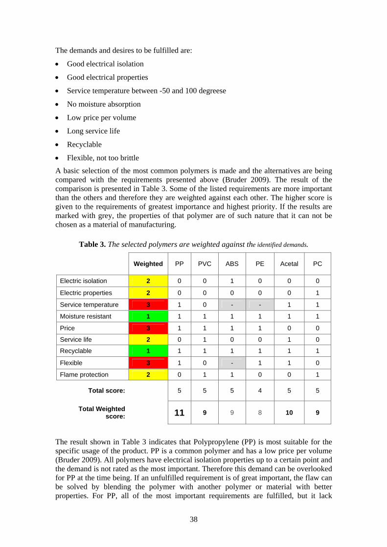
A basic selection of the most common polymers is made and the alternatives are being compared with the requirements presented above (Bruder 2009). The result of the comparison is presented in Table 3. Some of the listed requirements are more important than the others and therefore they are weighted against each other. The higher score is given to the requirements of greatest importance and highest priority. If the results are marked with grey, the properties of that polymer are of such nature that it can not be chosen as a material of manufacturing.
Table 3. The selected polymers are weighted against the identified demands.
Weighted PP PVC ABS PE Acetal PC
Electric isolation 2 0 0 1 0 0 0
Electric properties 2 0 0 0 0 0 1
Service temperature 3 1 0 - - 1 1
Moisture resistant 1 1 1 1 1 1 1
Price 3 1 1 1 1 0 0
Service life 2 0 1 0 0 1 0
Recyclable 1 1 1 1 1 1 1
Flexible 3 1 0 - 1 1 0
Flame protection 2 0 1 1 0 0 1
Total score: 5 5 5 4 5 5
Total Weighted score:
11 9 9 8 10 9
The result shown in Table 3 indicates that Polypropylene (PP) is most suitable for the specific usage of the product. PP is a common polymer and has a low price per volume (Bruder 2009). All polymers have electrical isolation properties up to a certain point and the demand is not rated as the most important. Therefore this demand can be overlooked for PP at the time being. If an unfulfilled requirement is of great important, the flaw can be solved by blending the polymer with another polymer or material with better properties. For PP, all of the most important requirements are fulfilled, but it lack
38

special electric properties. Therefore, before the pre series is released, the product should be tested for static electricity when in use in a RBS cabinet.
Choosing the manufacturing process was based on the complexity of the design and the material. Injection molding was therefore chosen as the manufacturing method. The technique has put some specific demands on the design and these have been taken under consideration during the development of the cabling concept.
5.1.1 Design for manufacturing
When developing the cable guides, the manufacturing method and the chosen material are of great importance because of their influence of the design. The CAD model is made with the specific requirements for the manufacturing method. Material thickness, the mold parting line and the material flow during the injection is some of the things taken under consideration during the development. In Figure 27 the parting line can bee seen and it is designed to make the separation of the molding parts simple and without damaging the product.
Figure 27. The molds parting line for the cable guides during the injection molding process.
5.1.2 Service life
A living hinge does not have as long service life as a hinge designed in metal. The choice of using it is motivated by the usage of the guide. When mounted in a cabinet it will be fastened in position with a snap buckle and when the cabling is made it is secured by the two covers. The hinges are at this moment only used once. A RBS has a service life between 10 and 20 years and the hinges will only be used again if the RBS has to be repaired or updated during this time. These possibilities could result in a handful of opportunities and it is far from the number of uses the living hinge could manage.
39

5.2 The cabling system The Interconnect designer is involved in the middle of the development process but the cabling is not considered until a very late stage. That is why the final design today often is made in short notice and without the opportunity to evaluate and optimize the result. It is like building a whole city by first constructing all the houses and buildings and then afterwards remember that people has to transport themselves from one building to another or communicate with each other. The cabling development has not yet reached that stage in the process but it is necessary if the system is going to be applied in different RBS cabinets. Therefore the idea of the cabling system is to involve the Interconnect designer earlier in the process by adding the guides to represent the cables before the actual cabling.
When the cabling is designed at the same time as the rest of the RBS it is easier to control the visual effect the cables has on the inside of the cabinets. The cabling in the different RBS cabinets becomes more unified and the mistakes are decreased when the route is more obvious. Two guides are developed to form the foundation of the cabling system, see Figure 28. The guides are a development of the concept chosen earlier in the process. The most important dimensions can be found in Appendix D – Straight cable guide drawing and Appendix E – Curved cable guide drawing.
Figure 28. Two guides are used to control the cabling, one straight and one curved.
By combining the two guides in different ways, depending on the specific need of every location, the cables can be guided between its connectors without interfering with the rest of the units. Several straight and curved guides are used to control the cables at
40

locations identified as more critical for its direction. The most important locations for the cabling are where the cables changes direction or when a lot of different cables gather from a wide range of angles. The curved detail is also designed to control the cable bend radius to prevent unexpected damaging that could affect the whole system. This is done by controlling the cable’s direction through the entire curve.
When attached inside the cabinet the guides together create a unit that will direct and control the cables in the preferred way. By using snap buckles for attachments in the cabinet the guides only needs two holes per guide for securing them in position, see Figure 29. Though the attachment is enough to secure the position, an additional attachment between the guides are designed and rails will make sure the guides works together as a single unit. This to ensure the guides attachment and position is not at risk because of stress that could arise when the cabling is assembled.
Figure 29. Snap buckles makes it easy to secure the guides inside the cabinet. The number of combinations that could be useful when applying the system is too many to present and therefore, only a handful of different types of combinations are described. Both guides can be combined with guides of the same type. This is useful when separating different types of cables from each other, such as power and signal cables, see Figure 30 and Figure 31. In the same way, the guides can be used to enhance the cabling capacity if one guide is not enough. The flexibility in capacity and sorting of cables makes the system suitable for a wide range of RBS cabinets. The final step is to include the guides in an earlier stage of the development process.
Figure 30. Two or more curved guides can be combined to increase the capacity of the system or to separate different types of cables.
41

Figure 31. Just like the curved guides, two or more straight guides can be combined depending on the specific need of different locations.
It is usual for the cables to take different directions at one location and the curved and straight guide can therefore be combined with each other. Figure 32 shows a common case were two curved and one straight guide is used. If necessary, it is possible to combine more guides, both for different directions and to increase the capacity of the system at a specific location.
Figure 32. The two different guides can be combined with each other to steer them in different directions.
42

The examples shown above are suitable for the most regular cabling, cables that take a chosen route in a strict fashion. Reality is not so simple and the existence of abnormalities is a known fact. That is why the design of the guides is adapted to take care of these specific situations by giving the cable more options. It is possible for a cable to go through the side walls of the guide that otherwise are used as support for the direction and an example can be seen in Figure 33.
Figure 33. The guides support the existence of abnormalities by adding more cabling options.
It is not unusual for the cables to come from different directions, even though they are connected to the same unit, and it makes the cabling difficult. To solve this common problem, the openings in the side walls of the guides can be used to gather them up before controlling the direction, see Figure 34. If positioned near a unit or between sub racks, up to eight cables can be gathered and if it isn’t enough, an additional guide is to be used. This function is important for the cabling system to operate properly and to minimize the disorder the cables otherwise will create.
43

Figure 34. It is often necessary to gather the cables before guiding them between units.
As shown, the number of configuration possibilities is great and most plausible situations and requirements can be fulfilled by combining the cable guides in different ways. When the cabling is made there is also important to make sure no cables are falling out. Two security covers have therefore been placed on each guide to secure the cables position and they are in turn fastened with a snap inside the guide, see Figure 35. To release the cables and the attachment again, a single push from the outside is needed.
Figure 35. The cables are kept in place with two security covers, fastened inside the guide. It is released again with a push from the outside.
The choice of designing the security cover to be fastened from the inside is made because of the realization that the outside of the guides becomes occupied when combined with another guide. By locating the cover on the inside, the problem can be solved, but with a limitation of the amount of cables per guide, as a consequence.
44

All the examples shown will together create a system that can be applied for most of the RBS cabinets. To give a clear view of the developed idea, an illustration is made for the cabling system applied in the SOD cabinet. The result is documented and can be seen in, see Figure 36.
Figure 36. A RBS 6101 cabinet, SOD. The cabling is made with the applied cabling system. Note that the SOD is not designed to include the newly developed cabling
system.
45

Study how the guides can by attached in the cabinet, both at the sides and next to the other units. This option makes it possible to design the cabling in three dimensions with cables directed in an angle out of the cabinet as well as in level with the other units.
5.2.1 Guidelines for development
It is necessary to include the cabling system in the Interconnect development process as a natural part of the cable design. To ease the implementation of the system, if it is to be developed further, guidelines are formulated. They are to help the designer determine when to begin with the cabling development, with what stage and how.
The guidelines for the cabling system are:
For the system to work properly, the guides’ location must be decided along with the rest of the included units in the RBS.
Begin to determine the route between the units with the largest number of connections and solve these situations before designing an entire route.
At the same time, locate junctions or areas where there are a natural gathering of cables. Study if it is suitable to give more space for the guides at one location than it is to spread them out.
Always have in mind that the cabling routes could be reduced a lot depending on the placement of the other units. Equally important is to remember that the development is a discussion between all involved areas of expertise.
When placing the guides, try to gather the cables as close to the unit as possible to begin the controlled route from the first connector to the other.
Fill every guide as far as it goes before adding another to reduce the necessary space. It is not to be done at the expense of the function.
Think in three dimensions. The guides can be attached at the sides as well as in level with the units.
Remember that abnormalities are to be expected and it is accepted to make unusual cabling.
If the distance between the two connectors is short, for example within sub racks and between RU units, it is not always necessary to make a route through a cable guide. The system is a support for the cables that can not be drawn in any other way and is therefore not a must for every single internal cable.
Use Mock-ups to test the cabling location and configuration. Prototypes, without the snap buckles, can be fastened with the use of double-coated adhesive tape.
Perform usability exercises to ensure that the cabling system does not interfere with the rest of the units during reparation or upgrades. If the system is developed along with the rest of the units, this should never become a problem.
46

47

6 Discussion and Conclusion
The purpose with the master thesis was to develop a cabling system to be applied in different RBS cabinets and to study how it could affect the cablings industrial design and usability. If possible, also to identify common elements and minimize the number of cable variations.
The result presented in Chapter 5 – Result, is a cabling system that can be adapted for different RBS cabinets and cabling requirements. With the two guides’ numerous combining possibilities, every configuration will have the most suitable cabling. An example is made for the outdoor cabinet, RBS 6101, and for future implementation, guidelines are formed to ease the design process for the Interconnect designer. I think that I have fulfilled the assignment of developing a cabling system for the RBS and created a look to unify the cabinets. The systems can be applied for different RBS cabinets thanks to the flexibility that the guides and also the overall system, have resulted in.
Today, the cabling design is made by the Interconnect designer at the very end of a project. Most of the time is used for the prestudy and feasibility which leads to less time left for the actual execution step. This way of working has to be changed in order to make the cabling optimal. By adding the guides to the number of units to be fitted inside the cabinet, the cabling layout has to be defined in order to make the proper cabling configuration. Space has to be reserved and holes for attachment made on the inside of cabined for the guides, which will result in more room for the cables. Today, no space is earmarked for the cables and it is common for the cabling to be ‘in the way’. The process of planning how it will look, before the actual cables are being in place, will increase the usability and enhance the industrial design tremendously. The Interconnect designers will have more to say about the location of other units than their own and become involved earlier in the development. If the design of the cabling is developed over a longer period of time, it will prevent late design changes.
Throughout the RBS cabinets, there are numerous of different strapping opportunities in form of guides, shelved, bars and hoops. The cabling system is supposed to replace these as far as possible in order to minimize the variation within the cabinets.
It has been a problem when the RBS units are upgraded or repaired that the cable ties have to be cut. New ties are not always available and inadequate solutions have therefore been applied. Cable ties are no longer needed with the new cabling system because of the guides being closed by the security covers.
Only by looking inside one of the outside cabinet, it becomes obvious that not all cables will go in straight lines and follow the designed route. For these few, the developed guides offer the possibility to take their own path through the system. In this way, the control of the cables is not at risk, though the effect of the cable bend radius should be tested. In a similar way, the cables can be gathered when coming from a wide range of directions. These two other uses of the guides make the system more complete by adding additional opportunities and flexibility.
6.1 Further work
When the assignment began, a part of it was to study if the number of cable variations could be decreased to lower the cost per cable. This subject is not studied further and no result is presented, due to the lack of time. I do believe that the cabling solution will
48

make it easier to determine the xed cable routes and standa uld lso affect the costs in another way, by only using two different guides instead of
ethod and material are two of the most important and the design
in the RBS cabinets already released to market, due to lack of space. If
if it is possible to reduce the cabling costs, because ofrd cabling. If applied in all RBS cabinets the system cofi
adifferent solutions for every RBS. The cabling system will eliminate the unnecessary strapping points and the cost per guide will be low because of the large quantity.
There are a lot of aspects to considerate when making the design of the cable guides. The manufacturing mhas to be optimized for the specific purposes and processes. The design for manufacturing is made to a certain point, but it could be taken even further.
By leaving the actual design of the cabling for the Interconnect designer, I hope to inspire them towards the new way of thinking. The cable guides, guidelines and the example of how it could look like (RBS 6101, SOD), is in my opinion, enough for Ericsson to take this result into a pre development project. If taken further, I believe that the system has the potential to solve the disorganized cabling, now situated in most RBS cabinets. Because of the need of a different way of working, it is not possible to apply the system included earlier in the product development process this should not be a problem.
It is important to remember that the change in the way of working has to be carried out together with all the concerned departments. The cabling system must be applied without problems, for all involved to really appreciate the improvement that the system should result in. The next step is therefore to present the result to the other intern interfaces mentioned earlier, such as Product management and Site etcetera. My advice to Ericsson and Interconnect is to take the cabling system concept into a pre development project and from that result, evaluate if the cabling system could be included as a unit in the future RBS.
49

7 References
7.1 Literature Bruder U. (nr 12, 2009), Värt att veta om plast, Plastforum
Cadick J. (1999). Cables and Wiring, Second edition.
Klemens G. (2010), The Cellphone: The history and Technology of the Gadget That Changed the World, McFarland & Company.
Moore G. F. (1982), Electric cables handbook, Third edition 1997, Blackwell Science Ltd.
Morton-Jones, D. H. (1986), Polymer Products- Design, materials and processing, Chapman and Hall Ltd
Roy S. K., Chanda M. (1987), Plastics technology handbook, Marcel Dekker.
Rozenblit B. (1999), Audio reality: myths debunked, truths revealed, First edition.
Siverbäck M. (2009), Enclosure & Power Usability – checklist, Ericsson Internal
Siverbäck M. (2009), Usability test, Ericsson Internal
Sweeney F. M. (1987), Reaction Injection molding Machinery and processes, Marcel Dekker.
7.2 Internet references Alla Bolag http://www.allabolag.se/5560160680/verksamhet, (used 2010-10-04)
Ericsson Intranet (2007) http://hwdp.ericsson.se/hwdpdrnd/hwdp2000.asp, (used 2010-06-09)
Ericsson Intranet http://internal.ericsson.com/, (used 2010-06-09)
Richco - Cable management http://www.richco.se/products/cable-management.html, (used 2010-09-10)
7.3 Interviews Karlsson Magnus, interviewed by Morberg E. Production Engineer (June 30,
2010).
Tolkstam Lars, interviewed by Morberg E. Supplier Quality Engineer (June 30, 2010).
Williamsson Ulf, interviewed by Morberg E. Experienced Service Engineer (July 5, 2010).
7.4 Visits Ericsson Production unit, Kumla 2010-06-30
Ericsson Production unit, Kumla 2010-08-31 together with Interconnect Employees.
50
7.5 Personal contacts Fagerlund Peter (Ericsson supervisor), Manager Interconnect design, Kista
[email protected] peter.fagerlun
Hansson Kjell, Senior Specialist R&D, Kista
Lemberg Marie, Interconnect designer, Kista
7.6 Pictures Ericsson Intranet (2007)
http://hwdp.ericsson.se/hwdpdrnd/hwdp2000.asp, (used 2010-06-09)
Intra Ericsson net http://internal.ericsson.com/, (used 2010-06-09)
Richco - Cable management http://www.richco.se/products/cable-management.html, (used 2010-09-10)
7.7 Computer programs Adobe Il lustrator, CS4, version 14.0.0 (2008)
Adobe Photoshop, CS4, version 11.0 (2008)
Adobe Acrobat Pro 9, version 9.2.0 (2009)
PIwin R20
Solid Edge ST
51

Appendix A) Description of the units in a RBS
A full configured RBS cabinet contains a wide range of different units. In Table A.1 their purpose and function are described.
Table A.1. All the included units in a RBS 6000 cabinet.
Abbrev Name of
Units Description
Climate system
a External
Fans
b Internal
Fans
c Heat
exchanger
Heater The Heater is optional in the RBS and activated if the temperature in the cabinet is below the threshold.
SCU Support
Control Unit
The SCU unit is the interface for smoke detector, cabinet lamp, door-switch, heaters, alarms and temperature sensors.
SHU Support Hub
Unit
The SHU connects peripheral units and is required in configurations equipped with PSU units.
PDU Power
Distribution Unit
There are two different models of PDU units, one located in the power sub rack and one slimmer located in a 19 inch slot. The PDU distributes fused -48 V DC power to DC-powered units.
PCU
Power Connection Unit, AC or
DC
The PCU is either the AC or DC interface for the RBS. The purpose is to connect the incoming power to the power supply units.
BFU Battery Fuse
Unit
The BFU can be installed either internal or external and supervises, connects and disconnects the battery backup.
PSU Power
Supply Unit
The PSU converts incoming voltage to -48 V DC system voltage.
PFU Power Filter
Unit
The PFU stabilizes the -48 V DC system voltage used in the RBS.
SAU Support
Alarm Unit
The SAU is a connection panel that connects the external alarms and transmission.
DU Digital Unit
The DU is the one of the brains behind the RBS and provides switching, traffic management, timing, baseband processing and radio interference. There are different types of DUs depending on the radio standard required. The last letter
1

tells what standard is used, LTE (L), GSM (G), WCDMA (W) or Multistandard (S).
RU Radio Unit
The RU converts digital data to analog signals and receives radio signals that are converted to digital signals. There are different types of RUs depending on the radio standard required. The last letter tells what standard is used, LTE (L), GSM (G), WCDMA (W) or Multistandard (S).
Smoke detector
Sends a signal if smoke is detected in the cabinet.
PCF Power
Connection Filter
The PCF connects the external power input for supply to the RBS cabinet. There are different types, depending on if AC or DC is used, if there are an external battery pack or an incoming power and if the BFU is internal or external.
OVP Over Voltage
Protection Protects the RBS from over voltage.
Internal light The lighting is activated when the door is opened.
2

Appendix B) Interview questions
This appendix is written in Swedish because of the language used during the meetings and interviews when these questions were answered. A summary of the result is written in English and is to be found in chapter 3.6 Interviews.
Frågor Kumla 1. Namn, Avdelning/Sektion
2. Arbetsuppgift på avdelningen/sektionen
- Titel?
- Vilka RBSer berörs av ditt arbete?
- När i ett projekt kommer du in i? Hur ser en typiskt arbetsuppgift ut när den når dig?
- Hur går din arbetsprocess till? Vilket steg börjar du med och vad blir det för resultat?
3. Usability
- Vad innebär Usability för dig?
- Din åsikt om Usabilityn i RBSerna idag?
- För mycket/lite?
- Känner du att du har någon möjlighet att påverka detta?
- Usability-övningar?
Deltagit?
I vilken utsträckning har det gjorts tidigare? Idag?
Åsikter om dessa? Nödvändiga?
4. Första spontana åsikten om kablaget i RBSerna (Innan vi diskuterar det!)
- Utseende? Designen? Usability?
- Funktion? Komplexitet? Ormbo? Rörigt?
- Skiljer sig det mellan olika RBSer?
5. I vilken utsträckning kommer du i kontakt med kablaget genom ditt arbete?
- På vilket sätt sker det?
6. Har du någon kontakt med Interconnect genom ditt arbete?
- På vilket sätt sker det? Med vem/vilka? Hur ofta?
7. Hur mycket känner du till om Interconnect’s designprocess?
- I vilket steg i deras process kommer du in?
- Har du haft någon möjlighet att påverka deras arbete?
- Designen? Arbetsprocessen? Resultatet?
- 1056 (Requirement specification) och 1074 (Manufacturing Specification)? Har du kontakt med dem under ditt arbete? På vilket sätt? Kan du vara med och påverka dessa?
3

- Om kontakt med 1074: Hur ser du på upplägget och strukturen? Förståelsen? Hur ser resultatet ut i jämförelse med teorin?
8. Har du identifierat några problem med kablaget?
- Känner du att det finns något som behöver ändras?
- Strappning? Buntband?
- Kabelhyllor och fästen? Balkar, plastdetaljer etc.
- Märkning av kablar?
- Antalet kabelvarianter?
- Placering av ingående enheter?
- Montering?
- Installering on Site?
- Byte av trasiga delar? Märkning av kablar?
- Annat?
9. Övrigt
- Andra tankar, åsikter och funderingar eller idéer om RBSerna eller det system som examensarbetet skall resultera i?
- Flytten från Gävle till Kumla: Vad är din arbetsuppgift?
10. Har du någon kontakt som du tror kan vara bra för mig att prata med?
11. Skulle det vara okej om jag senare i mitt projekt kontaktar dig för åsikter och synpunkter på ett utvecklat koncept?
4

Appendix C) From idea to concept
This Appendix describes all stages of development used in the development of the cabling system. The purpose is to give the reader an idea of how the result has been achieved.
As a first step, ideas were created during several brainstorming sessions and a handful of these ideas were developed into concepts. An identified problem was the labeling of the cable and in Figure C.1 you can see a concept which aims to make the labeling easier. The new label can be moved and rotated along the cable and therefore is the cable bend radius not affected. The information becomes more available because of the opportunity to choose the most suitable position. Two thin metal plates are attached to each other to form a small slot which can be opened by pressing the edges together and when released, the label seeks its natural form again.
Figure C.1. The label is made of two thin metal plates and can be moved by pressing the edges together.
Two different concepts concerning the cable guides and shelves were developed and designed in CAD (Computer Aided Design). These 3D models are used for evaluation and are the foundation of the concept choice, the two concepts can be seen in Figure C.2. The first concept, Concept 1, is made out of a polymeric material and two different guides can be combined to fit different requirements. The second, Concept 2, is made out of metal and the shape secures the cables from not falling out.
Figure C.2. Two the left are Concept 1 and to the right, Concept 2.
5
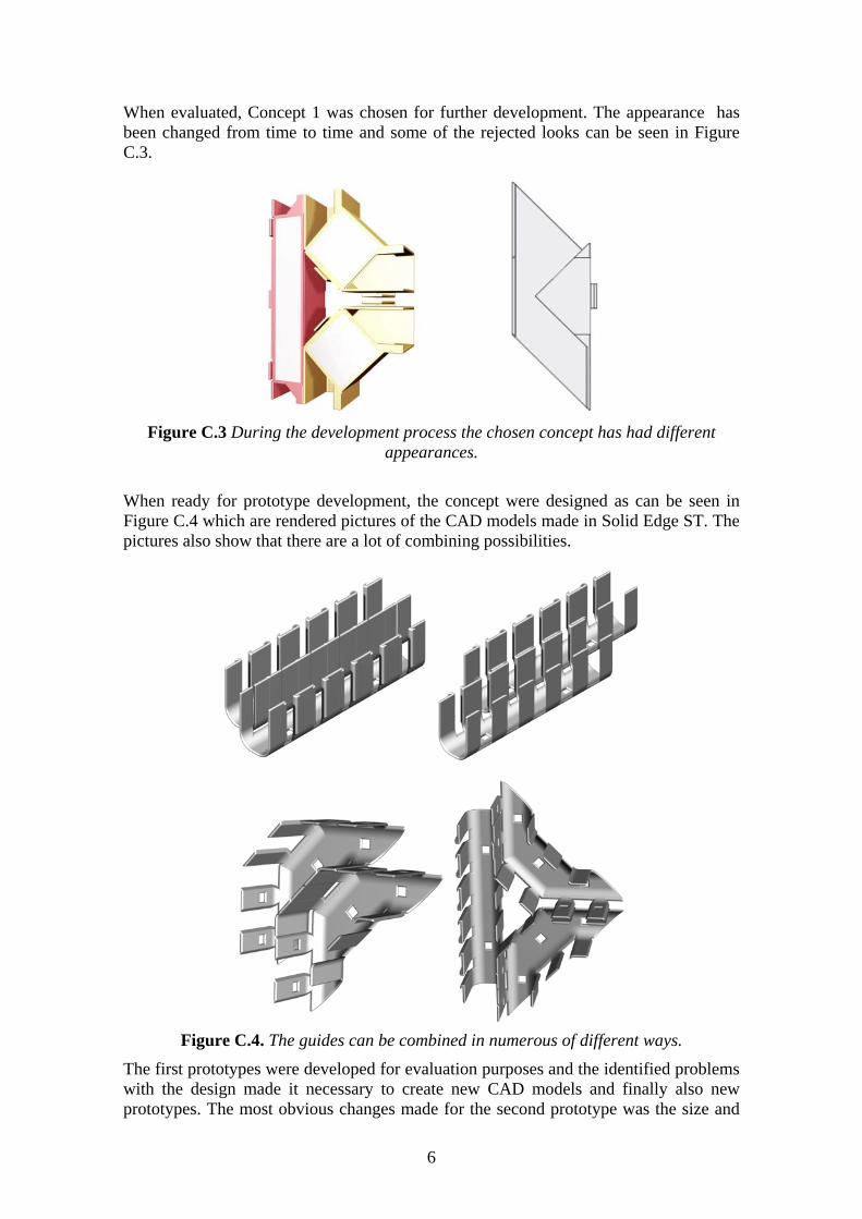
When evaluated, Concept 1 was chosen for further development. The appearance has been changed from time to time and some of the rejected looks can be seen in Figure C.3.
Figure C.3 During the development process the chosen concept has had different
appearances.
When ready for prototype development, the concept were designed as can be seen in Figure C.4 which are rendered pictures of the CAD models made in Solid Edge ST. The pictures also show that there are a lot of combining possibilities.
Figure C.4. The guides can be combined in numerous of different ways.
The first prototypes were developed for evaluation purposes and the identified problems with the design made it necessary to create new CAD models and finally also new prototypes. The most obvious changes made for the second prototype was the size and
6

the rails design for combining the guides. A picture of the first prototypes can be seen in Figure C.5.
Figure C.5. The first prototypes of the concept under development.
When studying the first prototypes, it became clear that the design was in need of further development. Identified design flaws were the rails, the attachment inside the RBS and the size of the guides among others.
The rails were redesigned with a T-shape for extra stability, when combining two or more guides. New snap buckles were also developed to ease the attachment procedure inside a RBS cabinet.
To enclose the guides, they were designed with two security covers for each detail, curved and straight. With a so called ‘Living hinge’ the security covers are produced in the same part as the rest of the guide, see Figure C.6. When bent 180 degrees it is secured in place with a snap attachment on the inside of the guide. A slight push from the outside will loosen it again.
Figure C.6. Two fastening details secure the cables inside the guides.
7

Evaluation before final design changes With the help of Interconnect designers, an evaluation is made for the concept before doing the final design changes. A presentation of the development was held during a meeting on the 8th of October and the identified problems that were discussed afterwards mainly were about the living hinge and the attachment in the RBS. The questions that were discussed are:
Are the rails for combining the guides necessary if they are fastened individually inside the cabinet?
How is the safety snaps opened when two straight guides combined together?
Is the Living hinge in the way when mounting the guides inside the cabinet or with each other?
A problem occurred when mounting the guides in the cabinet and the prototype broke because of tension caused by the cables when guided through with sharp turns. The event is noted and the design is to be more solid if to work as a system. The material used for prototype manufacturing is more brittle than the chosen material for serial production but as a precaution, the design is strengthen to avoid plastic deformation and exhaustion.
8
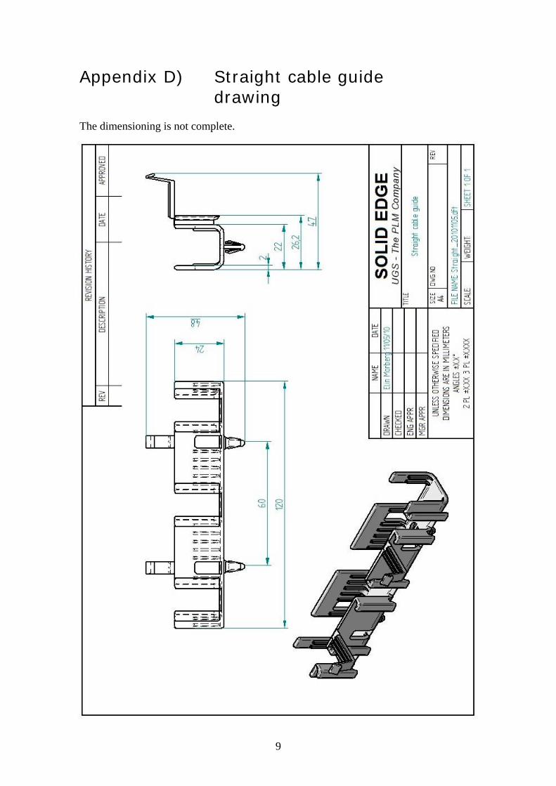
Appendix D) Straight cable guide drawing
The dimensioning is not complete.
9

10

Appendix E) Curved cable guide drawing
The dimensioning is not complete.
11