cable data collector (cdc): application guide
TRANSCRIPT
Cable Data Collector (CDC):
Application Guide

C:\Users\jzs\Dropbox (EA Technology)\EA Technology US - Restricted\LLC\Products & Services(1)\Cable Data
Collector\Proposition Guide USA R2 - CDC.docx
Page ii
Contents
1. Introduction ..................................................................................................................................................................... 1
2. PD in cables ..................................................................................................................................................................... 1
3. Principle of operation ................................................................................................................................................ 2
4. Advantages and disadvantages .......................................................................................................................... 6
5. Assessing circuit suitability .................................................................................................................................. 7
5.1 Earth straps ........................................................................................................................ 7
5.2 Safe access to earth straps ............................................................................................... 8
5.3 Sets of three phase conductors ........................................................................................ 9
6. Understanding cable construction ................................................................................................................. 10
6.1 Paper insulated lead covered (PILC) ............................................................................... 11
6.2 Paper insulated lead covered steel wire armoured (PILCSWA) ..................................... 12
6.3 Screened PILCSWA............................................................................................................ 13 6.3.1 Type ‘H’ screened PILCSWA ................................................................................. 14 6.3.2 Type ‘HSL’ screened PILCSWA ............................................................................. 15
6.4 Paper insulated corrugated aluminium sheath (PICAS) ................................................. 16
6.5 XLPE and EPR insulated cables ........................................................................................ 17
7. Example phase-resolved plots ........................................................................................................................... 18
8. Configuration types ................................................................................................................................................. 19
8.1 CDC hardware-only purchase ......................................................................................... 19
8.2 CDC & CDAS purchase..................................................................................................... 19
8.3 Training ............................................................................................................................ 19
8.4 Analysis and reporting only ............................................................................................ 19
8.5 Equipment Rental ............................................................................................................. 20

23 October 2014 Page 1 of 20
1. Introduction
The Cable Data Collector (CDC) is a portable instrument designed to allow the detection and possibly
location of partial discharge in medium voltage cables. It is functionally similar to VLF cable mapping,
but there are differences in how it operates that can offer significant advantages the customer
(depending on their circumstances and network configuration).
This method can also be referred to as ‘online’ cable mapping or testing, as provided the circuit is
configured in a manner that allows safe connection while the circuit is energised then no outage is
required. [Note that in order to obtain measurements the phase conductors must be energised by the
network they are connected to, or via a suitable power frequency test source].
The CDC instrument consists of both the data-gathering hardware and separate data analysis software
(CDAS).
The hardware in its ready-to-use state is shown below with customer supplied PC (Figure 1).
Figure 1. CDC hardware
2. PD in cables
Partial discharge in cables is of the ‘internal’ type, and therefore generates transient earth voltages
(TEVs) – as is detected by other instruments of our manufacture. CDC detects the currents that are the
underlying cause of TEV. PD degrades the insulation in cables just as it does in switchgear (Figure 2),
and if left to progress will eventually damage the insulation to a point where it can no longer withstand
its working voltage and failure will occur. Depending on the fault level, cable containment and other
factors this failure may be catastrophic, but in all cases that section of cable will be irreparably damaged
and require replacement.

23 October 2014 Page 2 of 20
Figure 2. Degradation of cable insulation (left: paper, right: XLPE)
As the degradation is occurring within the structure of the cable, it cannot be detected by visual
examination without destroying that cable. Clearly this would be an unacceptable method of
monitoring condition, and this is where electrical test techniques play a critical role.
3. Principle of operation
“In electrical engineering, partial discharge (PD) is a localised dielectric breakdown of a small portion
of a solid or fluid electrical insulation system under high voltage stress, which does not bridge the
space between two conductors”
For the moment, let us consider a three-core cable with no individual screens around the cores but a
steel wire armour layer around the cable’s circumference. This configuration was extremely popular
during the 1950s, 60s and 70s. A discharge from any phase will radiate energy onto the other two
phases and to earth: this energy comes from the phase conductor itself and what is taken from there
arrives on the other conductors. For simplicity, this is shown in the diagram below as all being
transferred to earth (Figure 3).

23 October 2014 Page 3 of 20
Figure 3. Simplified representation of cable PD
The signals that are present on the earth conductor are of very high frequency (up to several hundred
megahertz) and very small magnitude (perhaps only a few volts at most but more commonly in the
millivolt range). The CDC instrument detects signals, known as transient earth voltages (TEVs), by using
a radio frequency current transformer (RFCT) that is clipped around the ground at a safe and accessible
location. By determining the magnitude of the pulses in the signal, the magnitude of the discharges can
be derived. A basic diagram of this is shown below (Figure 4 – note 3 RFCTs can be connected to the
instrument simultaneously).

23 October 2014 Page 4 of 20
Figure 4. Basic diagram of CDC operation
There are many different kinds of cable construction in use around the world. They use different kinds
of insulating material, may be three-core or single-core, have screened or unscreened conductors and
may be armored or unarmored. However, provided that the nearest earth conductor to a phase that is
to be tested is accessible at a safe location (most likely at its terminations) and the gland is insulated
then the CDC can be utilised.
When the high frequency signal strikes the earth conductor, the energy in that pulse will set off in two
directions to each end of the cable. To the CDC observing activity at one end of the cable, the pulse
travelling towards it RFCTs will be ‘seen’ first as it has less distance to travel. The other pulse, travelling
away from the RFCTs, will strike the far end of the cable and most of its energy will be reflected back
at that change of impedance (this is transmission line theory). That reflected pulse will be seen by the
CDC later as it has travelled further (Figure 5).
By comparing the time of arrival between each pulse it is possible, using the time-of-flight principle, to
locate the point at which the discharge occurred. This is expressed as a percentage of cable length as
the instrument does not know how long the cable is. However, as a reasonable approximation to the
propagation speed will give a good indication of the cable length based upon these time measurements.
As the instrument has a finite time ‘window’ in which it looks for the reflected pulse, which is necessary
to separate out any extraneous signals/noise, the maximum length of cable that can be mapped is
10km. Note: the detection of the reflected pulse is not guaranteed and therefore it is not certain
that CDC can be used to locate the position of any PD activity – although it is likely to be able to
do so.

23 October 2014 Page 5 of 20
Figure 5. Representation of time-of-flight principle for discharge location
Depending on whether any changes of impedance are present along the cable’s route, such as joints,
then there may be other pulses present from additional reflections. These will typically be much smaller
as they are only partial reflections from small impedance changes and attenuated as they travel along
the earth conductor.
As the instrument relies upon the detection of small-magnitude high-frequency signals it can be
susceptible to interference from background noise. Modern equipment utilising ‘switch mode’ power
supplies (like PCs), uninterruptable power supplies (UPSs), variable speed drives (VSDs) and even
fluorescent lighting all radiate similar signals and these can obscure real discharge and/or prevent PD’s
location. However, in most cases it is possible to differentiate between this noise and ‘real’ PD. This is
achieved by considering the pulse waveform shape, using a series of software-based filters and a ‘phase
resolved plot’.
A phase resolved plot attempts to display at which point in the 360° mains cycle a discharge occurred.
‘Real’ PD will often be gathered in cloud-like formations near the positive and negative peaks of the
cycle (e.g. at around 90° and 270°) whilst other formations, such as a flat level, indicate an external
source (Figure 6 and Figure 7 respectively).
Phase conductor
Earth conductor
Cable route
Direct pulse
Reflected pulse
TRACE
Direct
pulse
Reflected
pulse

23 October 2014 Page 6 of 20
Figure 6. Phase-resolved plot showing true PD activity
Figure 7. Phase-resolved plot showing background noise
The mains cycle is derived from one of two possible sources. In order of preference due to their inherent
accuracy, which is selected automatically based upon their availability, these sources are: -
The low voltage mains connection used to the instrument (this is not a power source as that is
derived from the USB connection).
Derived from the RFCTs by looking for a 50Hz or 60Hz component. This relies on there being
an imbalance between the phases. This will be sufficiently accurate, provided the current can be
measured.
As these will not necessarily provide a true representation of the power frequency sine wave present on
the phase conductor being measured, the plots may be ‘skewed’ (i.e. phase shifted) left or right
somewhat. This is not of particular concern when conducting an analysis as the patterns are still
recognisable.
4. Advantages and disadvantages
First, it must be pointed out that techniques such as this are the only way of dealing with cable
degradation. Cables cannot be maintained or, as stated earlier, visually inspected. Electrical testing is
the only option available to customers wishing to manage the risk of cable failure.
The advantages of CDC are: -
No outage of the circuit to be tested is required.
The rate at which cables can be tested is higher than for VLF cable mapping, and therefore the
costs are lower. Measurements can be taken in 5-10 minutes then analysis takes approximately
45 minutes. As such, all circuits on a switchboard can generally be surveyed in a few hours at
most.
It can be used to make decisions regarding future management of the circuit, which may include
partial/full cable/joint replacements, targeted VLF mapping, further electrical measurements,
etc.

23 October 2014 Page 7 of 20
The disadvantages of CDC are: -
Can only be used where safe access to the earth conductor is available and the cable gland is
insulated from the equipment the cable is connected to.
Can be affected by noise, whether the source is external (such as an RF transmitter) or internal
from the load(s) connected to the circuit.
The instrument is only effective on circuits of 10km (6.2 miles). This is because the maximum
time window allowed to observe the reflection limits this (length based on propagation speed),
and will be less because of signals being attenuated as they travel along the cable (likely 8km
(5 miles) as a guideline for XLPE cables, but much shorter for paper insulated cables).
May not be able to locate discharges if there is excessive background noise.
For comparison against VLF cable mapping, the advantages of VLF are: -
It is influenced much less by noise than online techniques.
Circuits can be tested regardless of earthing configuration.
And its disadvantages: -
An outage of the circuit is required and at least one termination must be broken down to allow
for the test connections to be made.
Time consuming and therefore considerably more expensive than online techniques.
5. Assessing circuit suitability
This is perhaps the most important stage, as the success of any subsequent project is entirely
dependent upon the availability of access to suitable earth conductors.
5.1 Earth straps
The main problem of assessing suitability is that there must be earth straps accessible at the
termination to allow the instrument’s RFCTs to be clipped on and the gland must be insulated from the
equipment it is connected to. In order to be valid connection points, these earth straps must be
connected to the first earthed conductor that surrounds the phase conductor you wish to look for
discharge upon. The ‘basics’ to look for are shown below (Figure 8 and a real-world example in Figure
9).

23 October 2014 Page 8 of 20
Figure 8. Connection point for RFCT on a 11KV Pad Mount Transformer
Figure 9. Real-world example of RFCT connection in the United States
This is valid for both single-core cables and three-core cables where there are no screens around
individual cores that are bonded together prior to the location that the RFCT is to be applied at.
5.2 Safe access to earth straps
Access to earth conductors as illustrated previously is not always available from outside of the
switchgear, although it may be from inside a cable termination box. In this situation, which is fairly
common, a cover would have to be removed or door opened in order to apply the RFCTs. Depending
on the safety practices in place at a particular company this may not be allowed, or, and Arc Flash
suite with hood should be used when placing the RFCTs on the grounds.

23 October 2014 Page 9 of 20
In order to access the enclosed earth connections, each panel will have to be isolated in turn to allow
the cover to be removed and RFCTs applied (if there are any exposed conducting parts within then
earths must also be applied before any covers are removed). This will clearly negate some of the
advantages of online cable mapping, but it should still be borne in mind that such an approach removes
the need to remove terminations etc and is therefore still quicker than VLF. As the CDC is not protected
against high voltages, the operator must be certain that the RFCTs will not come into contact with
live conductors, covers are securely replaced during measurements and that the leads are
securely routed.
When opening a cable box to undertake the alternative action above for access to enclosed earth
connections, it may be considered that a loop of earth strap material could be passed through a new
hole in the base of the cable box: this would facilitate simpler access for CDC measurements both
immediately and in the future. For critical cables that will be tested on a regular basis one option is to
permanently install the RFCTs and bring out the test cables to an external test box such as one shown
below in Figure 10.
Figure 10. External Test Box wired to permanently mounted RFCTs
5.3 Sets of three phase conductors
The CDC instrument can gather measurements from three RFCTs simultaneously during any single
measurement run. This means that it can measure the discharges on a single set of three phase
conductors at any one time: this may be different to a ‘circuit’ and is an important distinction if the
time required to gather and then report upon the data is to be estimated with any accuracy.
It may not be apparent from a single line diagram (SLD) what the composition of a single circuit actually
is. Below is an example of a transformer with both upstream and downstream circuit breakers plus
intervening cables (Figure ).

23 October 2014 Page 10 of 20
Figure 11. Example single line diagram (SLD)
Each single vertical line representing the cables actually consists of at least three individual phase
conductors. These may be contained in a single three-core cable or three single-core cables;
alternatively there may be more than one cable per phase! This can be confusing and you will need to
refer to a site survey or a cable schedule to find this information.
6. Understanding cable construction
In order to assist with understanding how various cable constructions can impact on the suitability of
the CDC instrument, this section gives an overview on common cable types.
Older cables will generally be insulated with paper which has been impregnated with an oil-based
compound. There are still very large quantities of these cables in service as they are generally very
reliable and most of the network expansions in the 60s and 70s used them.
Newer cables, particularly those installed from the mid-80s onwards, are much more likely to be
insulated with cross-linked polyethylene (XLPE) – a form of plastic. Much less common, is ethylene
propylene rubber (EPR) insulation.
The usability of the CDC is still mostly dependent on the termination of any cable type.

23 October 2014 Page 11 of 20
6.1 Paper insulated lead covered (PILC)
Figure 12. PILC cable
This single-core example has no armor layer. Earthing in this case is provided by the lead sheath, which
should generally be bonded at one end of the cable’s route to earth. If the termination at that end is
suitable, it should be possible to attach an RFCT.
1. Conductor: Stranded copper.
2. Conductor screen: Semiconducting carbon paper tapes.
3. Insulation: Mass impregnated non draining (MIND)
compound filled paper.
4. Insulation screen: Carbon paper and copper tape or
aluminium foil.
5. Sheath: Lead.
6. Anti-corrosion: Bitumen layer covering lead.
7. Oversheath: Polyvinylchloride (PVC).

23 October 2014 Page 12 of 20
6.2 Paper insulated lead covered steel wire armoured (PILCSWA)
Figure 13. PILCSWA cable
PILCSWA cable in the configuration shown above (which is also known as ‘belted’) is extremely common
on older industrial sites. The earth is only provided by the combined lead sheath and armorings, which
are commoned together at the terminations. The earth connection is generally only made at one end of
the cable route, at which location it should be possible to attach an RFCT depending on the termination.
As all three phase conductors are contained within a single earth plane the phase on which any PD may
be occurring cannot be differentiated.
1. Conductor: Stranded aluminium/copper.
2. Conductor screen: Semiconducting carbon paper tapes.
3. Insulation: Mass impregnated non draining (MIND)
compound filled paper.
4. Fillers and belt insulation: MIND.
5. Belt screen: Carbon paper tapes.
6. Sheath: Lead.
7. Bedding: Wrapped layers of paper and bitumen
impregnated hessian tape.
8. Armour: Galvanised steel wire.
9. Serving coating: Wrapped layers of bitumen impregnated
hessian tape.

23 October 2014 Page 13 of 20
6.3 Screened PILCSWA
Figure 14. Screened PILCSWA cable
Screened cables can be categorised into two sub-types, as outlined below.
1. Note the only difference from normal PILCSWA is the
presence of aluminium foil or copper tapes around
each phase conductor’s semiconducting layer.

23 October 2014 Page 14 of 20
6.3.1 Type ‘H’ screened PILCSWA
Figure 15. Type ‘H’ cable
The ‘H’ stands for ‘Hochstadter’, and refers to cables where there is a screen around individual
conductors then an outer layer of lead sheath – therefore no belt insulation is required. In this cable
type, it is unlikely that the RFCTs can be successfully applied as the screens will be commoned together
at the termination with no access to them.
1. Conductor: Stranded aluminium or copper.
2. Conductor screen: Semiconducting carbon paper tapes.
3. Insulation: MIND.
4. Insulation screen: Typically pinholed aluminium foil
laminate.
5. Filler: MIND.
6. Carbon woven fabric tape.
7. Sheath: Lead.
8. Anti-corrosion: Bitumen layer.
9. Oversheath: Medium density polyethylene (MDPE).

23 October 2014 Page 15 of 20
6.3.2 Type ‘HSL’ screened PILCSWA
Figure 16. Type ‘HSL’ cable
‘HSL’ refers to cables where each phase conductor is individually both screened and sheathed,
essentially so that it is a group of three single-phase cables in an oversheath. As with ‘H’ type, it is
unlikely that the RFCTs can be successfully applied as the screens will be commoned together at the
termination with no access to them.
1. Conductor: Stranded aluminium or copper.
2. Conductor screen: Semiconducting carbon paper tapes.
3. Insulation: MIND.
4. Insulation screen: Typically pinholed aluminium foil
laminate.
5. Sheath: Lead.
6. Bedding
7. Filler: Bitumen impregnated jute.
8. Bedding: Bitumen impregnated hessian tape.
9. Armour: Galvanised steel wire.
10. Serving coating: Bitumen impregnated hessian tape or
polyvinylchloride (PVC).

23 October 2014 Page 16 of 20
6.4 Paper insulated corrugated aluminium sheath (PICAS)
Essentially PICAS cable can be thought of as being functionally identical to PILCSWA, with the only
physical difference being the lead and armour layers replaced with a corrugated aluminium layer. The
same restrictions apply in that the phase on which any PD may be occurring cannot be differentiated.
1. Conductor: stranded aluminium.
2. Conductor screen: semiconducting carbon paper tapes.
3. Insulation: MIND.
4. Fillers and belt insulation: MIND.
5. Belt screen: Semiconducting carbon paper tapes.
6. Sheath: Corrugated aluminium.
7. Anti-corrosion: Bitumen layer.
8. Oversheath: Polyvinylchloride (PVC).
23 October 2014 Page 17 of 20
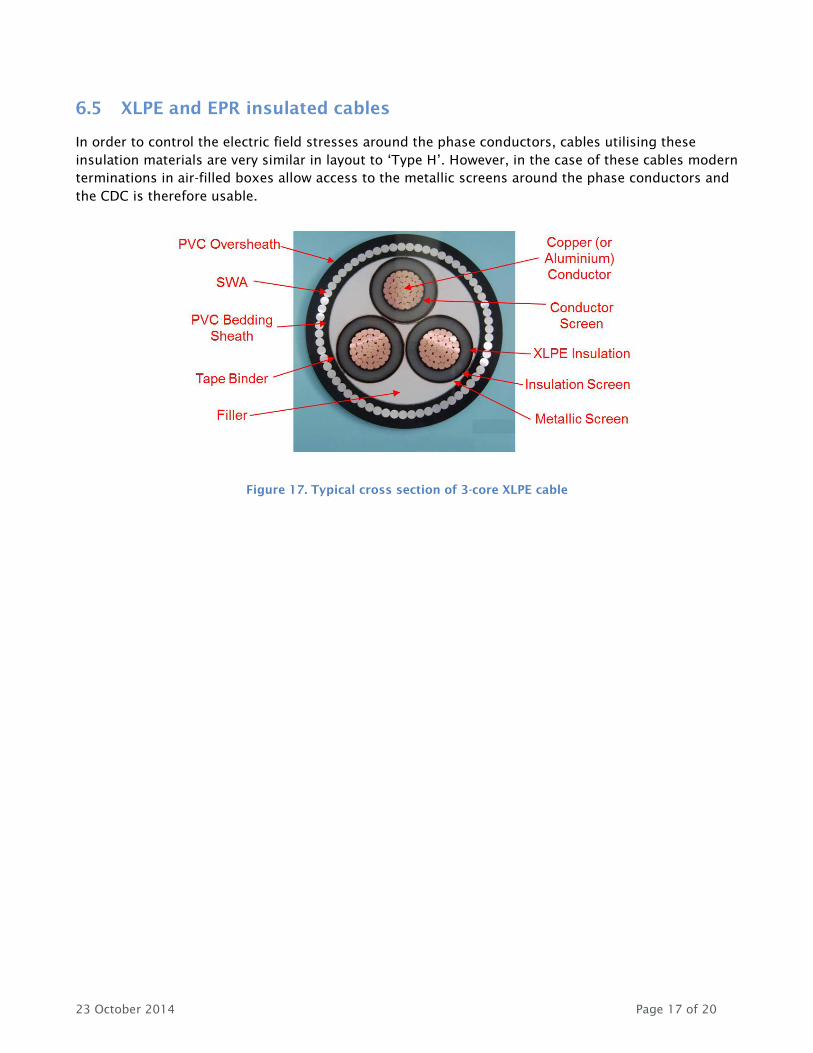
6.5 XLPE and EPR insulated cables
In order to control the electric field stresses around the phase conductors, cables utilising these
insulation materials are very similar in layout to ‘Type H’. However, in the case of these cables modern
terminations in air-filled boxes allow access to the metallic screens around the phase conductors and
the CDC is therefore usable.
Figure 17. Typical cross section of 3-core XLPE cable

23 October 2014 Page 18 of 20
7. Example phase-resolved plots
These are provided for general information.
Figure 18. Clusters of PD activity
Figure 19. VSD/machine noise

23 October 2014 Page 19 of 20
Figure 20. Background noise
8. Configuration types
There are a variety of propositions that we offer based upon this single instrument.
8.1 CDC hardware-only purchase
Customers may elect to purchase the hardware only with no CDAS software licence. In this case, they
shall be reliant upon others to carry out the data analysis for them (see below).
8.2 CDC & CDAS purchase
This is a traditional approach to an instrument sale, the customer becomes self-sufficient in online cable
mapping.
8.3 Training
Substation Assessment, Product Support and others can offer training to customers who have purchased
a stand-alone CDC or combined CDC and CDAS.
8.4 Analysis and reporting only
EA Technology LLC can undertake data analysis and reporting on data gathered by others, particularly
customers who have purchased the CDC hardware only.

23 October 2014 Page 20 of 20
8.5 Equipment Rental
EA Technology LLC has units available for rental on a weekly and monthly basis.

www.eatechnology.com
Australia | China | Singapore | UAE | Europe | USA
Main reception: +44(0) 151 339 4181
EA Technology, LLC 400 Morris Avenue
Denville, NJ 07834
Global Footprint
We provide products, services and support for customers in 90 countries, through our offices in
Australia, China, Europe, Singapore, UAE and USA, together with more than 40 distribution partners.
Our Expertise
We provide world-leading asset management solutions for power plant and networks.
Our customers include electricity generation, transmission and distribution companies, together
with major power plant operators in the private and public sectors.
Our products, services, management systems and knowledge enable customers to:
Prevent outages
Assess the condition of assets
Understand why assets fail
Optimise network operations
Make smarter investment decisions
Build smarter grids
Achieve the latest standards
Develop their power skills